092ICEPOWER250AS
富士通 PRiMERGY BX920 s2 双插槽服务器板数据表说明书

Datasheet Fujitsu PRiMERGY BX920 s2 Dual-sockEt sERvER BlaDEDatasheetFujitsu PRiMERGY BX920 s2 Dual-sockEt sERvER BlaDEunivERsal Dual-sockEl sERvER BlaDE with hiGh coMPutinG anD i/o PERFoRMancE in asMall FoRM FactoRthe PRiMERGY BX Blade servers are the ideal choice for data center solutions of today and tomorrow.our blade servers provide maximum performance and maximum redundancy, but with only minimumspace requirements, low power consumption and a reduction in the time and effort required for cabling.the PRiMERGY BX system family is designed to share components between chassis in order to reactquickly and easily to changing business requirements. storage and server blades can be added withoutany extra effort, as would be needed when cabling or adding management software. You can use thesame applications, rely on the same server and storage components and establish connections to thesame networks. The PRIMERGY BX Blade Servers are flexible and have complete control via a centraladministration instance that is redundant in design; they minimize administrative time and effort, freeingyou of time-consuming administration tasks. our build-to-order process ensures that only completelyinstalled and previously tested solutions are supplied, which have been precisely adapted to individualrequirements and which will grow with future business requirements.PRIMeRGY BX920 s2the PRiMERGY BX920 s2 server Blade uses the cPus of the intel® Xeon® processor 5500 and 5600series and thus the latest and most powerful members of the Xeon® family. utilizing the QuickPatharchitecture and special on-chip memory controllers, the cPus of the intel® Xeon® processor 5600 serieseasily exceed the capacities of the previous generation. the BX920 s2 server blade can host two ofthese processors, with up to two hard drives, 144 GB of DDR3 memory as well as two dual-channel intel82575 Gigabit Ethernet controllers. the protection against data loss can be increased via the Ras function(now available) called channel sparing of the main memory modules in conjunction with cPus from theintel® Xeon® processor 5600 series. the BX920 s2 is ideal for virtualization using hypervisors such asvMware® EsXi, Microsoft hyper-v™, or citrix Xenserver™. in addition, the PRiMERGY BX920 s2 bladesare equipped with the state-of-the-art integrated Remote Management controller (iRMc s2) and - withits wide range of processor, disk and memory options, it provides it managers with the performance andscalability they need for all their data center applications. the optimal and secure support of i/o-intensiveapplications, such as terminal servers is ensured by the optional use of a RaiD controller with write-backcache and BBu.FeatuRes anD BeneFItstechnIcal DetaIlsMaInBoaRDMainboard type D 3030chipset intel® 5500Processor quantity and type 1 - 2 x intel® Xeon® processor 5500 series / intel® Xeon® processor 5600 seriesPRocessoR intel® Xeon® processor E5503(2c/2t, 2.00 Ghz, slc: 4 x 256 kB, tlc: 4 MB, turbo: no, 4.8 Gt/s, Mem bus: 800 Mhz, 80 w)intel® Xeon® processor E5506(4c/4t, 2.13 Ghz, slc: 4 x 256 kB, tlc: 4 MB, turbo: no, 4.8 Gt/s, Mem bus: 800 Mhz, 80 w)intel® Xeon® processor E5507(4c/4t, 2.26 Ghz, slc: 4 x 256 kB, tlc: 4 MB, turbo: no, 4.8 Gt/s, Mem bus: 800 Mhz, 80 w)intel® Xeon® processor E5620(4c/8t, 2.40 Ghz, slc: 4 x 256 kB, tlc: 12 MB, turbo: 1/1/2/2, 5.86 Gt/s, Mem bus: 1066 Mhz, 80 w)intel® Xeon® processor E5630(4c/8t, 2.53 Ghz, slc: 4 x 256 kB, tlc: 12 MB, turbo: 1/1/2/2, 5.86 Gt/s, Mem bus: 1066 Mhz, 80 w)intel® Xeon® processor E5640(4c/8t, 2.66 Ghz, slc: 4 x 256 kB, tlc: 12 MB, turbo: 1/1/2/2, 5.86 Gt/s, Mem bus: 1066 Mhz, 80 w)intel® Xeon® processor l5609(4c/4t, 1.86 Ghz, slc: 4 x 256 kB, tlc: 4 MB, turbo: no, 4.8 Gt/s, Mem bus: 800 Mhz, 40 w)intel® Xeon® processor l5630(4c/8t, 2.13 Ghz, slc: 4 x 256 kB, tlc: 12 MB, turbo: 1/1/2/2, 5.86 Gt/s, Mem bus: 1066 Mhz, 40 w)intel® Xeon® processor l5640(6c/12t, 2.26 Ghz, slc: 4 x 256 kB, tlc: 12 MB, turbo: 2/2/3/3/4/4, 6.4 Gt/s, Mem bus: 1333 Mhz, 60 w)intel® Xeon® processor X5650(6c/12t, 2.66 Ghz, slc: 4 x 256 kB, tlc: 12 MB, turbo: 2/2/2/2/3/3, 6.4 Gt/s, Mem bus: 1333 Mhz, 95 w)intel® Xeon® processor X5660(6c/12t, 2.80 Ghz, slc: 4 x 256 kB, tlc: 12 MB, turbo: 2/2/2/2/3/3, 6.4 Gt/s, Mem bus: 1333 Mhz, 95 w)intel® Xeon® processor X5667(4c/8t, 3.06 Ghz, slc: 4 x 256 kB, tlc: 12 MB, turbo: 2/2/3/3, 6.4 Gt/s, Mem bus: 1333 Mhz, 95 w)intel® Xeon® processor X5670(6c/12t, 2.93 Ghz, slc: 4 x 256 kB, tlc: 12 MB, turbo: 2/2/2/2/3/3, 6.4 Gt/s, Mem bus: 1333 Mhz, 95 w) Memory slots9 (6 slots on cPu 1, 3 slots on cPu 2)Memory slot type DiMM (DDR3)Memory capacity (min. - max.) 2 GB - 144 GBMemory protection advanced EccMemory scrubbingsDDc (chipkill™)Memory Mirroring supporthot-spare memory supportMeMoRY MoDules InDePenDent MoDe 2 GB (1 module(s) 2 GB) DDR3, registered, Ecc, 1333 Mhz, Pc3-10600, DiMM2 GB (1 module(s) 2 GB) DDR3, unbuffered, Ecc, 1333 Mhz, Pc3-10600, DiMM 2 GB (1 module(s) 2 GB) DDR3 lv, unbuffered, Ecc, 1333 Mhz, Pc3-10600, DiMM4 GB (1 module(s) 4 GB) DDR3, registered, Ecc, 1333 Mhz, Pc3-10600, DiMM4 GB (1 module(s) 4 GB) DDR3 lv, registered, Ecc, 1333 Mhz, Pc3-10600, DiMM 8 GB (1 module(s) 8 GB) DDR3, registered, Ecc, 1333 Mhz, Pc3-10600, DiMM8 GB (1 module(s) 8 GB) DDR3 lv, registered, Ecc, 1333 Mhz, Pc3-10600, DiMM 16 GB (1 module(s) 16 GB) DDR3, registered, Ecc, 1066 Mhz, Pc3-8500, DiMMMeMoRY MoDules MIRRoReD MoDe 4 GB (2 module(s) 2 GB) DDR3, registered, Ecc, 1333 Mhz, Pc3-10600, DiMM8 GB (2 module(s) 4 GB) DDR3, registered, Ecc, 1333 Mhz, Pc3-10600, DiMM8 GB (2 module(s) 4 GB) DDR3 lv, registered, Ecc, 1333 Mhz, Pc3-10600, DiMM16 GB (2 module(s) 8 GB) DDR3, registered, Ecc, 1333 Mhz, Pc3-10600, DiMM16 GB (2 module(s) 8 GB) DDR3 lv, registered, Ecc, 1333 Mhz, Pc3-10600, DiMM32 GB (2 module(s) 16 GB) DDR3, registered, Ecc, 1066 Mhz, Pc3-8500, DiMMMeMoRY MoDules sPaRe oR PeR-FoRMance MoDe 6 GB (3 module(s) 2 GB) DDR3, registered, Ecc, 1333 Mhz, Pc3-10600, DiMM12 GB (3 module(s) 4 GB) DDR3, registered, Ecc, 1333 Mhz, Pc3-10600, DiMM 12 GB (3 module(s) 4 GB) DDR3 lv, registered, Ecc, 1333 Mhz, Pc3-10600, DiMM 24 GB (3 module(s) 8 GB) DDR3, registered, Ecc, 1333 Mhz, Pc3-10600, DiMM 24 GB (3 module(s) 16 GB) DDR3 lv, registered, Ecc, 1333 Mhz, Pc3-10600, DiMM 48 GB (3 module(s) 16 GB) DDR3, registered, Ecc, 1066 Mhz, Pc3-8500, DiMMInteRFacesusB ports 4 x usB at the front via special cableGraphics (15-pin) 1 x vGa at the front via special cableserial connection 1 x Rs232 (9-pin) at the front via special cablelan / ethernet (RJ-45) 4 x Gbit Ethernet via Midplane to Ethernet connection Bladeservice lan (RJ45)Service LAN traffic can be switched to shared onboard Gbit LAN portI/o contRolleR on BoaRDRaID controller integrated sas RaiD 0/1 for hDD´slan controller 2 x intel® 82575, 4 x 10/100/1000 Mbit/s Ethernet,Remote Management controller integrated Remote Management controller (iRMc s2, 32 MB attached memory incl. graphics controller) trusted Platform Module (tPM)Infineon / 1.2 (option)slotsPcI-express 2.0 x8 2 x BX900 Mezzanine Mezzanine cardDRIVe BaYshard disk bays2oPeRatInG Paneloperating buttons on/off switchiD buttonstatus leDs Power (amber / green)system status (amber)lan connection (green)Identification (blue)css (yellow)BIosBIos features local and remote update via serverview update Manageronline update tools for main windows and linux versionssMBios v2.6Remote PXE boot supportRemote iscsi boot supportsuPPoRteD oPeRatInG sYsteMssupported operating systems Microsoft® windows server® 2008 R2Microsoft® windows server® 2008Microsoft® windows server® 2003 R2novell susE linux Enterprise serverRed hat Enterprise linuxcitrix® Xenserver™vMware infrastructurenote: support of other linux derivatives on demandoperating system release link /software/dl.aspx?id=a9e600b9-e4cb-4f48-aa41-632f69058421seRVeR ManaGeMentstandard PDa Prefailure Detection and anaylsisasR&R automatic server Recovery and Restartserverview suite:sv installation Managersv operation Managersv RaiD Managersv update Managementsv Power Managementsv agentsserverview Remote Management (iRMc s2)iRMc s2 advanced PackOnline update packages for BIOS, firmware drivers and ServerView Agentsserverview integration solutions for Microsoft sMs, MoM, scoM, sccM and altirisDeployment solution serverview Deployment Manager (fully functional 30-day trial version)option serverview vioM - virtual io Managerserverview integration for tivoli tEc®, tivoli netview, hP nnM and hP operations Managerserver Management notes Regarding operating system dependencies and product details for serverview suite software products see dedicatedproduct datasheets.DIMensIons / WeIGhtDimensions (W x D x h)45 x 500 x 210 mmWeight 5.75 kgWeight notes Actual weight may vary depending on configurationenVIRonMentaltemperature note in accordance with the corresponding PRiMERGY BX900 system unitcoMPlIanceGermany Gseurope cE class a *Global cBRohs (Restriction of hazardous substances)wEEE (waste electrical and electronical equipment)compliance notes in combination with corresponding PRiMERGY BX system unitthere is general compliance with the safety requirements of all European countries and north america. national approvalsrequired in order to satisfy statutory regulations or for other reasons can be applied for on request.compliance link https:///sites/certificates/default.aspxcoMPonentshaRD DIsk DRIVes ssD sata, 3 Gb/s, 64 GB, hot-plug, 2.5-inch, enterprisessD sata, 3 Gb/s, 32 GB, hot-plug, 2.5-inch, enterprisehDD sata, 3 Gb/s, 500 GB, 7200 rpm, hot-plug, 2.5-inch, business criticalhDD sata, 3 Gb/s, 320 GB, 5400 rpm, hot-plug, 2.5-inch, economichDD sata, 3 Gb/s, 160 GB, 7200 rpm, hot-plug, 2.5-inch, business criticalhDD sata, 3 Gb/s, 160 GB, 5400 rpm, hot-plug, 2.5-inch, economichDD sas, 6 Gb/s, 300 GB, 10000 rpm, hot-plug, 2.5-inch, enterprisehDD sas, 6 Gb/s, 146 GB, 15000 rpm, hot-plug, 2.5-inch, enterprisehDD sas, 6 Gb/s, 146 GB, 10000 rpm, hot-plug, 2.5-inch, enterprisehDD sas, 6 Gb/s, 73 GB, 15000 rpm, hot-plug, 2.5-inch, enterprisehard disk notes one Gigabyte equals one billion bytes, when referring to hard disk drive capacity.MezzanIne caRDs Fibre channel Mezzanine card 2 x 8 Gb Emulex (Mc-Fc82E), Pcie x4Ethernet Mezzanine card 4 ports int. x 1 Gb Fujitsu (), Pcie x4InfiniBand Mezzanine Card 2 x 40 Gb Mellanox (), PCIe x8Ethernet Mezzanine card 2 x 10 Gb, Pcie Gen2 x8WaRRantYstandard Warranty 3 yearsservice level (depending on country) MaIntenance anD suPPoRt seRVIces - the PeRFect eXtensIon Recommended service7x24, onsite Response time: 4h spare Parts availability 5 yearsservice Weblink /supportservicecontactFujitsu liMitEDMies-van-der-Rohe-straße 8 80807 München Germanywebsite: 2010-05-03 cE-Enproject for reducing burdens on the environment.using our global know-how, we aim to resolveissues of environmental energy efficiencythrough it.Please find further information at http://www./global/about/environment/delivery subject to availability. any liability thatthe data and illustrations are complete, actualor correct is excluded. Designations may betrademarks and/or copyrights of the respectivemanufacturer, the use of which by third partiesfor their own purposes may infringe the rights ofsuch owner。
复盛空压机学习资料之一

2.
3.
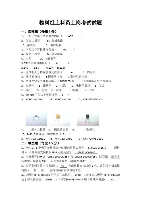
4.
5.
轻故障(空滤、油分、油滤堵塞)报警不停机,重故障(排气高温或电气故障)报警 停机,必须做到故障排除后,空压机才能再启动。清除故障使用“紧停/复位”按钮。同 时有两个以上故障,状态显示优先级高的,清除后,显示优先级其次的,直至所有故 障全部清完。(重故障优先于轻故障)。 1、相序故障指示 空压机接通电源,若R、S、T相序错误,面板上相序故障灯亮,并会在液晶显示屏上显 示相序错误。禁止空压机启动;改接电源相序。 2、主电机过载指示灯 空压机在运行过程中,发生主电机过载,主电机过载灯亮,空压机停机。 3、风扇电机过载指示灯 空压机在运行过程中,发生风扇电机过载,风扇电机过载灯亮,空压机停机。 4、排气温度指示灯 空压机在运行过程中,排气温度超过报警温度时,排气温度指示灯闪烁,排气温度超过 保护温度时,指示灯常亮,空压机停机。 5、传感器报警指示灯 温度和压力传感器短路、断路或故障时,传感谢器报警灯常用亮。 6、备用指示灯 空压机运行中,当压力大于上限设定值+0.05Mpa(此值可设定)持续10s,备用指示灯 亮,空压机停机。
端子排预留如下信号: A、重故障信号扩展输出接点(当出现重故障报警:主机过载、风机过载 、相序异常、排气压力过高或排气高温等时,此触点接通,作为重故 障报警信号输出)。 B、轻故障信号扩展输出接点(空气滤清器、油气分离器、油过滤器阻塞 报警信号综合控输出)。 C、“近控/远控”方式输出接点(液晶屏参数设置中选择为近控,触点断 开;液晶屏参数设置中选择为远控,触点接通)。 D、电源指示输出点(空压机运行后,触点接通)。 E、运行信号扩展输出接点(空 压机运行后,触点接通)。 F、远程启动、远程停止控制接点(液晶屏参数设置中选择远控时,通过 这二个接点可远程启动或停止空压机)。 控制系统预留有RS485通讯接口,支持MODBUS协议的子集。
IR公司_大功率MOS管选型

I DContinuous Drain Current(A)70°Micro3Surface Mount PackagesV (BR)DSSDrain-to-Source Breakdown Voltage (V)R DS(on)On-State Resistance ()ΩI D Continuous Drain Current 25°C(A)R ΘMax.Thermal Resistance (°C/W)1FaxonDemand Number Case Outline KeyPartNumberPD Max.PowerDissipation (W)N-ChannelLogic LevelIRLML2402*912570.54200.25 1.20.95230H1IRLML2803912580.54300.251.20.93230P-ChannelLogic LevelIRLML6302*912590.54-200.6-0.62-4.8230H1IRLML5103912600.54-300.6-0.61-4.8230* Indicates low VGS(th), which can operate at VGS = 2.7VMeasured at ambient for Micro3, Micro6, Micro8, SO-8, and SOT-223 package styles. All others measured at case.1Micro3SO-8D-PakD -PakSOT-227Micro6SOT-223Micro82 Illustrations not to scaleI DContinuous Drain Current(A)70°Micro6Surface Mount PackagesV (BR)DSSDrain-to-Source Breakdown Voltage (V)R DS(on)On-State Resistance ()ΩI D Continuous Drain Current 25°C(A)R ΘMax.Thermal Resistance (°C/W)1FaxonDemand Number Case Outline KeyPartNumberPD Max.PowerDissipation (W)N-ChannelLogic LevelIRLMS1902915401.7200.10 3.2 2.675H2IRLMS1503915081.7300.103.22.675P-ChannelLogic LevelIRLMS6702*914141.7-200.20-2.3-1.975H2IRLMS5703914131.7-300.20-2.3-1.975* Indicates low VGS(th), which can operate at VGS = 2.7VMeasured at ambient for Micro3, Micro6, Micro8, SO-8, and SOT-223 package styles. All others measured at case.1Micro3SO-8D-PakD -PakSOT-227Micro6SOT-223Micro82 Illustrations not to scaleI DContinuous Drain Current(A)70°Micro8Surface Mount PackagesV (BR)DSSDrain-to-Source Breakdown Voltage (V)R DS(on)On-State Resistance ()ΩI D Continuous Drain Current 25°C(A)R ΘMax.Thermal Resistance (°C/W)1FaxonDemand Number Case Outline KeyPart NumberP D Max.PowerDissipation (W)N-Channel Logic LevelIRF7601* 912611.820 0.035 5.7 4.6 70 H3IRF7603 912621.830 0.035 5.6 4.5 70Dual N-Channel Logic LevelIRF7501* 912651.220 0.135 2.4 1.9 100 H3IRF7503 912661.2530 0.135 2.4 1.9 100P-Channel Logic LevelIRF7604* 912631.8-20 0.09 -3.6 -2.9 70 H3IRF7606 912641.8-30 0.09 -3.6 -2.9 70Dual P-Channel Logic LevelIRF7504* 912671.25-20 0.27 -1.7 -1.4 100 H3IRF7506 912681.25-30 0.27 -1.7 -1.4 100Dual N- and P-Channel Logic LevelIRF7507* 912691.2520 0.1352.4 1.9 100 H3-20 0.27 -1.7 -1.4IRF7509 912701.2530 0.135 2.4 1.9 100-30 0.27 -1.7 -1.4* Indicates low VGS(th), which can operate at VGS = 2.7VMeasured at ambient for Micro3, Micro6, Micro8, SO-8, and SOT-223 package styles. All others measured at case.1Micro3SO-8D-Pak D -PakSOT-227Micro6SOT-223Micro8 2 Illustrations not to scaleI DContinuous Drain Current(A)70°SO-8Surface Mount PackagesV (BR)DSSDrain-to-Source Breakdown Voltage (V)R DS(on)On-State Resistance ()ΩI D Continuous Drain Current 25°C(A)R ΘMax.Thermal Resistance (°C/W)1FaxonDemand Number Case Outline KeyPart Number P D Max.PowerDissipation (W)N-ChannelIRF7413913302.5300.011139.250H4IRF7413A 916132.5300.0135128.450IRF9410915622.5300.0375.850Dual N-ChannelIRF7311914352.0200.029 6.6 5.362.5H4IRF7313914802.0300.029 6.5 5.262.5IRF7333917002.0300.10 3.5 2.862.5917002.0300.050 4.9 3.962.5IRF9956915592.0300.103.52.862.5Dual P-ChannelIRF7314914352.0-200.058-5.3-4.362.5H4IRF7316915052.0-300.058-4.9-3.962.5IRF9953915602.0-300.25-2.3-1.862.5* Indicates low VGS(th), which can operate at VGS = 2.7VMeasured at ambient for Micro3, Micro6, Micro8, SO-8, and SOT-223 package styles. All others measured at case.1Micro3SO-8D-PakD -PakSOT-227Micro6SOT-223Micro82 Illustrations not to scaleI DContinuous Drain Current(A)70°SO-8Surface Mount PackagesV (BR)DSSDrain-to-Source Breakdown Voltage (V)R DS(on)On-State Resistance ()ΩI D Continuous Drain Current 25°C(A)RΘMax.ThermalResistance(°C/W)1FaxonDemand Number Case Outline KeyPart NumberP D Max.PowerDissipation (W)Dual N- and P-ChannelIRF7317 915682.020 0.029 6.6 5.3 62.5 H42.0-20 0.058 -5.3 -4.3 62.5IRF9952 915622.030 0.103.5 2.8 62.5915622.0-30 0.25 -2.3 -1.8 62.5IRF7319 916062.030 0.029 6.5 5.2 62.52.0-30 0.058 -4.9 -3.9 62.5* Indicates low VGS(th), which can operate at VGS = 2.7VMeasured at ambient for Micro3, Micro6, Micro8, SO-8, and SOT-223 package styles. All others measured at case.1Micro3SO-8D-Pak D -PakSOT-227Micro6SOT-223Micro8 2 Illustrations not to scaleI DContinuous Drain Current(A)70°SO-8Surface Mount PackagesV (BR)DSSDrain-to-Source Breakdown Voltage (V)R DS(on)On-State Resistance ()ΩI D Continuous Drain Current 25°C(A)R ΘMax.Thermal Resistance (°C/W)1FaxonDemand Number Case Outline KeyPart Number P D Max.PowerDissipation (W)N-ChannelLogic LevelIRF7401912442.5200.0228.77.050H4IRF7201911002.5300.0307.0 5.650IRF7403912452.5300.0228.55.450Dual N-ChannelLogic LevelIRF7101908712.0200.10 3.5 2.362.5H4IRF7301912382.0200.050 5.2 4.162.5IRF7303912392.0300.050 4.9 3.962.5IRF7103910952.0500.1303.02.362.5P-ChannelLogic LevelIRF7204911032.5-200.060-5.3-4.250H4IRF7404912462.5-200.040-6.7-5.450IRF7205911042.5-300.070-4.6-3.750IRF7406912472.5-300.045-5.8-3.750IRF7416913562.5-300.02-10-7.150* Indicates low VGS(th), which can operate at VGS = 2.7VMeasured at ambient for Micro3, Micro6, Micro8, SO-8, and SOT-223 package styles. All others measured at case.1Micro3SO-8D-PakD -PakSOT-227Micro6SOT-223Micro82 Illustrations not to scaleI DContinuous Drain Current(A)70°SO-8Surface Mount PackagesV (BR)DSSDrain-to-Source Breakdown Voltage (V)R DS(on)On-State Resistance ()ΩI D Continuous Drain Current 25°C(A)R ΘMax.Thermal Resistance (°C/W)1FaxonDemand Number Case Outline KeyPart Number P D Max.PowerDissipation (W)Dual P-ChannelLogic LevelIRF7104910962.0-200.250-2.3-1.862.5H4IRF7304912402.0-200.090-4.3-3.462.5IRF7306912412.0-300.10-3.6-2.962.5Dual N- and P-Channe Logic LevelIRF7307912421.4200.050 4.3 3.490H4-200.090-3.6-2.9IRF7105910972.0250.1093.5 2.862.52-250.25-2.3-1.862IRF7309912432.0300.050 4.9 3.962.5-300.10-3.6-2.9* Indicates low VGS(th), which can operate at VGS = 2.7VMeasured at ambient for Micro3, Micro6, Micro8, SO-8, and SOT-223 package styles. All others measured at case.1Micro3SO-8D-PakD -PakSOT-227Micro6SOT-223Micro82 Illustrations not to scaleI DContinuous Drain Current(A)70°SOT-223Surface Mount PackagesV (BR)DSSDrain-to-Source Breakdown Voltage (V)R DS(on)On-State Resistance ()ΩI D Continuous Drain Current 25°C(A)R ΘMax.Thermal Resistance (°C/W)1FaxonDemand Number Case Outline KeyPart Number P D Max.PowerDissipation (W)N-ChannelIRFL4105913812.1550.045 3.7 3.060H6IRFL110908612.01000.54 1.50.9660IRFL4310913682.11000.20 1.6 1.360IRFL21090868 2.02001.50.960.660IRFL214908622.02502.00.790.560P-ChannelIRFL9110908642.0-1001.2-1.1-0.6960H6N-ChannelLogic LevelIRLL3303913792.1300.031 4.6 3.760H6IRLL014N 914992.1550.14 2.0 1.660IRLL2705913802.1550.043.83.060* Indicates low VGS(th), which can operate at VGS = 2.7VMeasured at ambient for Micro3, Micro6, Micro8, SO-8, and SOT-223 package styles. All others measured at case.1Micro3SO-8D-PakD -PakSOT-227Micro6SOT-223Micro82 Illustrations not to scaleI DContinuous Drain Current(A)100°D-PakSurface Mount PackagesV (BR)DSSDrain-to-Source Breakdown Voltage (V)R DS(on)On-State Resistance ()ΩI D Continuous Drain Current 25°C(A)R ΘMax.Thermal Resistance (°C/W)1FaxonDemand Number Case Outline KeyPart Number P D Max.PowerDissipation (W)N-ChannelIRFR33039164257300.0313321 2.2H7IRFR024N9133638550.0751610 3.3IRFR41059130248550.0452516 2.7IRFR12059131869550.0273723 1.8IRFR11090524251000.54 4.3 2.75IRFR120N 91365391000.219.1 5.8 3.2IRFR391091364521000.11159.5 2.4IRFR2109052625200 1.5 2.6 1.75IRFR22090525422000.8 4.833IRFR21490703252502 2.2 1.45IRFR2249060042250 1.1 3.8 2.43IRFR3109059725400 3.6 1.7 1.15IRFR3209059842400 1.8 3.123IRFR42090599425003 2.4 1.53IRFRC2090637426004.421.33* Indicates low VGS(th), which can operate at VGS = 2.7VMeasured at ambient for Micro3, Micro6, Micro8, SO-8, and SOT-223 package styles. All others measured at case.1Micro3SO-8D-PakD -PakSOT-227Micro6SOT-223Micro82 Illustrations not to scaleI DContinuous Drain Current(A)100°D-PakSurface Mount PackagesV (BR)DSSDrain-to-Source Breakdown Voltage (V)R DS(on)On-State Resistance ()ΩI D Continuous Drain Current 25°C(A)R ΘMax.Thermal Resistance (°C/W)1FaxonDemand Number Case Outline KeyPart Number P D Max.PowerDissipation (W)P-ChannelIRFR55059161057-550.11-18-11 2.2H7IRFR53059140289-550.065-28-18 1.4IRFR90149065425-600.5-5.1-3.25IRFR90249065542-600.28-8.8-5.63IRFR91109051925-100 1.2-3.1-25IRFR91209052042-1000.6-5.6-3.63IRFR9120N 9150739-1000.48-6.5-4.1 3.2IRFR92109052125-2003-1.9-1.25IRFR92209052242-200 1.5-3.6-2.33IRFR92149165850-250 3.0-2.7-1.7 2.5IRFR93109166350-4007.0-1.8-1.12.5* Indicates low VGS(th), which can operate at VGS = 2.7VMeasured at ambient for Micro3, Micro6, Micro8, SO-8, and SOT-223 package styles. All others measured at case.1Micro3SO-8D-PakD -PakSOT-227Micro6SOT-223Micro82 Illustrations not to scaleI DContinuous Drain Current(A)100°D-PakSurface Mount PackagesV (BR)DSSDrain-to-Source Breakdown Voltage (V)R DS(on)On-State Resistance ()ΩI D Continuous Drain Current 25°C(A)R ΘMax.Thermal Resistance (°C/W)1FaxonDemand Number Case Outline KeyPart Number P D Max.PowerDissipation (W)N-ChannelLogic LevelIRLR27039133538300.0452214 3.3H7IRLR33039131657300.0313321 2.2IRLR31039133369300.0194629 1.8IRLR024N 9136338550.0651711 3.3IRLR27059131746550.042415 2.7IRLR29059133469550.0273623 1.8IRLR120N 91541391000.18511 6.9 3.2IRLR341091607521000.10159.52.4* Indicates low VGS(th), which can operate at VGS = 2.7VMeasured at ambient for Micro3, Micro6, Micro8, SO-8, and SOT-223 package styles. All others measured at case.1Micro3SO-8D-PakD -PakSOT-227Micro6SOT-223Micro82 Illustrations not to scaleI DContinuous Drain Current(A)100°D 2PakSurface Mount PackagesV (BR)DSSDrain-to-Source Breakdown Voltage (V)R DS(on)On-State Resistance ()ΩI D Continuous Drain Current 25°C(A)R ΘMax.Thermal Resistance (°C/W)1FaxonDemand Number Case Outline KeyPart NumberP D Max.PowerDissipation (W)N-ChannelIRFZ24NS 913554555 0.07 17 12 3.3 H10IRFZ34NS 913116855 0.04 29 20 2.2IRFZ44NS 9131511055 0.022 49 35 1.4IRFZ46NS 9130512055 0.020 53 37 1.3IRFZ48NS 9140814055 0.016 64 45 1.1IRF1010NS 913723.855 0.011 84 60 40IRF3205S 9130420055 0.008 110 80 0.75IRFZ44ES 9171411060 0.023 48 34 1.4IRF1010ES 9172017060 0.012 83 59 0.90IRF2807S 9151815075 0.013 71 50 1.0IRF520NS 9134047100 0.2 9.5 6.7 3.2IRF530NS 9135263100 0.11 15 11 2.4IRF540NS 91342110100 0.052 27 19 1.6IRF1310NS 91514120100 0.036 36 25 1.3IRF3710S 91310150100 0.028 46 33 1.0IRF3315S 9161794150 0.082 21 15 1.6IRF3415S 91509150150 0.042 37 26 1.0IRFBC20S 9.101450600 4.4 2.2 1.4 2.5IRFBC30S 9101574600 2.2 3.6 2.3 1.7IRFBC40S 91016130600 1.2 6.2 3.9 1.0* Indicates low VGS(th), which can operate at VGS = 2.7VMeasured at ambient for Micro3, Micro6, Micro8, SO-8, and SOT-223 package styles. All others measured at case.1Micro3SO-8D-Pak D -PakSOT-227Micro6SOT-223Micro8 2 Illustrations not to scaleI DContinuous Drain Current(A)100°D 2PakSurface Mount PackagesV (BR)DSSDrain-to-Source Breakdown Voltage (V)R DS(on)On-State Resistance ()ΩI D Continuous Drain Current 25°C(A)R ΘMax.Thermal Resistance (°C/W)1FaxonDemandNumberCase Outline KeyPart NumberP D Max.PowerDissipation (W)IRFBF20S 9166554900 8.0 1.7 1.1 2.3 H10P-ChannelIRF5305S 91386110-55 0.06 -31 -22 1.4 H10IRF4905S 914783.8-55 0.02 -74 -52 40IRF9520NS 9152247-100 0.48 -6.7 -4.8 3.2IRF9530NS 9152375-100 0.20 -14 -9.9 2.0IRF9540NS 9148394-100 0.117 -19 -13 1.6IRF5210S 91405150-100 0.06 -35 -25 1.0* Indicates low VGS(th), which can operate at VGS = 2.7VMeasured at ambient for Micro3, Micro6, Micro8, SO-8, and SOT-223 package styles. All others measured at case.1Micro3SO-8D-Pak D -PakSOT-227Micro6SOT-223Micro8 2 Illustrations not to scaleI DContinuous Drain Current(A)100°D 2PakSurface Mount PackagesV (BR)DSSDrain-to-Source Breakdown Voltage (V)R DS(on)On-State Resistance ()ΩI D Continuous Drain Current 25°C(A)R ΘMax.Thermal Resistance (°C/W)1FaxonDemand Number Case Outline KeyPart NumberP D Max.PowerDissipation (W)N-Channel Logic LevelIRL3302S 916925720 0.020 39 25 2.2 H10IRL3202S916756920 0.016 48 30 1.8IRL3102S 916918920 0.013 61 39 1.4IRL3402S 9169311020 0.01 85 54 1.1IRL3502S 9167614020 0.007 110 67 0.89IRL2703S 913604530 0.04 24 17 3.3IRL3303S 913236830 0.026 38 27 2.2IRL3103S 9133811030 0.014 64 45 1.4IRL2203NS 9136717030 0.007 116 82 0.90IRL3803S 9131920030 0.006 140 98 0.75IRLZ24NS 913584555 0.06 18 13 3.3IRLZ34NS 913086855 0.035 30 21 2.2IRLZ44NS 9134711055 0.022 47 33 1.4IRL3705NS 9150217055 0.01 89 63 0.90IRL2505S 9132620055 0.008 104 74 0.75IRLZ44S 9090615060 0.028 50 36 1.0IRL530NS 9134963100 0.1 15 11 2.4IRL2910S 91376150100 0.026 48 34 1.0* Indicates low VGS(th), which can operate at VGS = 2.7VMeasured at ambient for Micro3, Micro6, Micro8, SO-8, and SOT-223 package styles. All others measured at case.1Micro3SO-8D-Pak D -PakSOT-227Micro6SOT-223Micro8 2 Illustrations not to scaleI DContinuous Drain Current(A)100°SOT-227Surface Mount PackagesV (BR)DSSDrain-to-Source Breakdown Voltage (V)R DS(on)On-State Resistance ()ΩI D Continuous DrainCurrent 25°C(A)RΘMax.Thermal Resistance (°C/W)1FaxonDemand Number Case Outline KeyPart Number P D Max.PowerDissipation (W)N-ChannelFully Isolated Low ChargeFA38SA50LC 916155005000.1338240.25H21FA57SA50LC916506255000.0857360.20* Indicates low VGS(th), which can operate at VGS = 2.7VMeasured at ambient for Micro3, Micro6, Micro8, SO-8, and SOT-223 package styles. All others measured at case.1Micro3SO-8D-PakD -PakSOT-227Micro6SOT-223Micro82 Illustrations not to scaleI DContinuous Drain Current(A)100°I-PakThrough-Hole PackagesV (BR)DSSDrain-to-Source Breakdown Voltage (V)R DS(on)On-State Resistance ()ΩI D Continuous Drain Current 25°C(A)R ΘMax.Thermal Resistance (°C/W)1FaxonDemand Number Case Outline KeyPart Number P D Max.PowerDissipation (W)N-ChannelIRFU33039164257300.0313321 2.2H8IRFU024N 9133638550.0751610 3.3IRFU41059130248550.0452519 2.7IRFU12059131869550.0273723 1.8IRFU11090524251000.54 4.3 2.7 5.0IRFU120N 91365391000.219.1 5.8 3.2IRFU391091364521000.11159.5 2.4IRFU2109052625200 1.5 2.6 1.7 5.0IRFU22090525422000.80 4.8 3.0 3.0IRFU2149070325250 2.0 2.2 1.4 5.0IRFU2249060042250 1.1 3.8 2.4 3.0IRFU3109059725400 3.6 1.7 1.1 5.0IRFU3209059842400 1.8 3.1 2.0 3.0IRFU4209059942500 3.0 2.4 1.5 3.0IRFUC2090637426004.42.01.33.0I-PakTO-220 FullPakTO-262TO-247HEXDIPTO-220AB Illustrations not to scale** Not ratedI DContinuous Drain Current(A)100°I-PakThrough-Hole PackagesV (BR)DSSDrain-to-Source Breakdown Voltage (V)R DS(on)On-State Resistance ()ΩI D Continuous Drain Current 25°C(A)R ΘMax.Thermal Resistance (°C/W)1FaxonDemand Number Case Outline KeyPart Number P D Max.PowerDissipation (W)P-ChannelIRFU55059161057-550.11-18-11 2.2H8IRFU53059140289-550.065-28-18 1.4IRFU90149065425-600.50-5.1-3.2 5.0IRFU90249065542-600.28-8.8-5.6 3.0IRFU91109051925-100 1.2-3.1-2.0 5.0IRFU91209052042-1000.60-5.6-3.6 3.0IRFU9120N 9150739-1000.48-6.5-4.1 3.2IRFU92109052125-200 3.0-1.9-1.2 5.0IRFU92209052242-200 1.5-3.6-2.3 3.0IRFU92149165850-2503.0-2.7-1.7 2.5IRFU93109166350-4007.0-1.8-1.12.5N-ChannelLogic LevelIRLU27039133538300.0452214 3.3H8IRLU33039131657300.0313321 2.2IRLU31039133369300.0194629 1.8IRLU024N 9136338550.0651711 3.3IRLU27059131746550.04241715IRLU29059133469550.0273623 1.8IRLU120N 91541391000.18511 6.9 3.2IRLU341091607521000.10159.52.4I-PakTO-220 FullPakTO-262TO-247HEXDIPTO-220AB Illustrations not to scale** Not ratedI DContinuous Drain Current(A)100°HEXDIPThrough-Hole PackagesV (BR)DSSDrain-to-Source Breakdown Voltage (V)R DS(on)On-State Resistance ()ΩI D Continuous Drain Current 25°C(A)R ΘMax.Thermal Resistance (°C/W)1FaxonDemand Number Case Outline KeyPart Number P D Max.PowerDissipation (W)N-ChannelIRFD014907001.3600.2 1.7 1.2120H9IRFD024906991.3600.1 2.5 1.8120IRFD110903281.31000.54 1.00.71120IRFD120903851.31000.27 1.30.94120IRFD210903861.3200 1.50.60.38120IRFD220904171.32000.80.80.50120IRFD214912711.3250 2.00.570.32120IRFD224912721.3250 1.10.760.43120IRFD310912251.3400 3.60.420.23120IRFD320912261.3400 1.80.600.33120IRFD420912271.3500 3.00.460.26120IRFDC20912281.36004.40.320.21120I-PakTO-220 FullPakTO-262TO-247HEXDIPTO-220AB Illustrations not to scale** Not ratedI D Continuous Drain Current (A)100°TO-220Qg TotalGate Charge(nC)Through-Hole PackagesV (BR)DSSDrain-to-Source Breakdown Voltage (V)R DS(on)On-State Resistance ()ΩI D Continuous Drain Current 25°C (A)R ΘMax.Thermal Resistance(°C/W)1Faxon Demand Number Case OutlineKeyPart Number P D Max.Power Dissipation (W)N-ChannelLow ChargeIRF737LC91314743000.75 6.1** 1.7 3.9H11IRF740LC 910681254000.5510** 1.039IRF840LC 910691255000.858.0** 1.039IRFBC40LC910701256001.26.2**1.039I-PakTO-220 FullPakTO-262TO-247HEXDIPTO-220AB Illustrations not to scale** Not ratedI DContinuous Drain Current(A)100°TO-220ABThrough-Hole PackagesV (BR)DSSDrain-to-Source Breakdown Voltage (V)R DS(on)On-State Resistance ()ΩI D Continuous Drain Current 25°C(A)R ΘMax.Thermal Resistance (°C/W)1FaxonDemand Number Case Outline KeyPart Number P D Max.PowerDissipation (W)N-ChannelIRFZ24N 9135445550.071712 3.3H12IRFZ34N9127656550.042618 2.7IRFZ44N 9130383550.0244129 1.8IRFZ46N 9127788550.024633 1.7IRFZ48N 9140694550.0165337 1.6IRF1010N 91278130550.0127251 1.2IRF320591279150550.0089869 1.0IRFZ34E 9167268600.0422820 2.2IRFZ44E 91671110600.0234834 1.4IRF1010E 91670170600.01281570.90IRF280791517150750.0137150 1.0IRF520N 91339471000.209.5 6.79.5IRF530N 91351601000.111511 2.4IRF540N 91341941000.0522719 1.6IRF1310N 916111201000.0363625 1.3IRF3710913091501000.0284633 1.0IRF331591623941500.0822115 1.6IRF3415914771501500.0423726 1.0IRFBC209062350600 4.4 2.2 1.4 2.5IRFBC309048274600 2.2 3.6 2.3 1.7IRFBC4090506125600 1.2 6.2 3.9 1.0IRFBE2090610548006.51.81.22.3I-PakTO-220 FullPakTO-262TO-247HEXDIPTO-220AB Illustrations not to scale** Not ratedI DContinuous Drain Current(A)100°TO-220ABThrough-Hole PackagesV (BR)DSSDrain-to-Source Breakdown Voltage (V)R DS(on)On-State Resistance ()ΩI D Continuous Drain Current 25°C(A)R ΘMax.Thermal Resistance (°C/W)1FaxonDemand Number Case Outline KeyPart Number P D Max.PowerDissipation (W)IRFBE3090613125800 3.0 4.1 2.6 2.0H12IRFBF3090616125900 3.7 3.6 2.3 1.0IRFBG209060454100011 1.40.86 2.3IRFBG309062012510005.03.12.01.0P-ChannelIRF9Z24N 9148445-550.175-12-8.53.3H12IRF9Z34N 9148556-550.10-17-12 2.7IRF530591385110-550.06-31-22 1.4IRF490591280150-550.02-64-45 1.0IRF9530N 9148275-1000.20-13-9.2 2.0IRF9540N 9143794-1000.117-19-13 1.6IRF521091434150-1000.06-35-25 1.0IRF62159147983-1500.29-11-7.81.8I-PakTO-220 FullPakTO-262TO-247HEXDIPTO-220AB Illustrations not to scale** Not ratedI DContinuous Drain Current(A)100°TO-220ABThrough-Hole PackagesV (BR)DSSDrain-to-Source Breakdown Voltage (V)R DS(on)On-State Resistance ()ΩI D Continuous Drain Current 25°C(A)R ΘMax.Thermal Resistance (°C/W)1FaxonDemand Number Case Outline KeyPart NumberP D Max.PowerDissipation (W)N-Channel Logic LevelIRL3302 916965720 0.020 39 25 2.2 H12IRL3202 916956920 0.016 48 30 1.8IRL3102 916948920 0.013 61 39 1.4IRL3402 9169711020 0.01 85 54 1.1IRL3502 9169814020 0.007 110 67 0.89IRL2703 913594530 0.04 24 17 3.3IRL3303 913225630 0.026 34 24 2.7IRL3103 913378330 0.014 56 40 1.8IRL2203N 9136613030 0.007 100 71 1.230 0.007 61 43 3.2IRL3803 9130115030 0.006 120 83 1.0IRLZ24N 913574555 0.06 18 13 3.3IRLZ34N 913075655 0.035 27 19 2.7IRLZ44N 913468355 0.022 41 29 1.8IRL3705N 9137013055 0.01 77 54 1.2IRL2505 9132520055 0.008 104 74 0.75IRL520N 9149447100 0.18 10 7.1 3.2IRL530N 9134863100 0.10 15 11 2.4IRL540N 9149594100 0.044 30 21 1.6IRL2910 91375150100 0.026 48 34 1.0I-PakTO-220 FullPakTO-262TO-247HEXDIPTO-220AB Illustrations not to scale** Not ratedI D Continuous Drain Current (A)100°TO-220 FullPak (Fully Isolated)Qg TotalGate Charge(nC)Through-Hole PackagesV (BR)DSSDrain-to-Source Breakdown Voltage (V)R DS(on)On-State Resistance ()ΩI D Continuous DrainCurrent 25°C(A)R ΘMax.Thermal Resistance (°C/W)1Fax on Demand Number Case OutlineKeyPart Number P D Max.Power Dissipation (W)N-ChannelLow ChargeIRFI740GLC91209404000.55 6.0** 3.139H13IRFI840GLC 91208405000.85 4.8** 3.139IRFIBC40GLC91211406001.24.0**3.139I-PakTO-220 FullPakTO-262TO-247HEXDIPTO-220AB Illustrations not to scale** Not ratedI DContinuous Drain Current(A)100°TO-220 FullPak (Fully Isolated)Through-Hole PackagesV (BR)DSSDrain-to-Source Breakdown Voltage (V)R DS(on)On-State Resistance ()ΩI D Continuous Drain Current 25°C(A)R ΘMax.Thermal Resistance (°C/W)1FaxonDemand Number Case Outline KeyPart Number P D Max.PowerDissipation (W)N-ChannelIRFIZ24N 9150126550.07139.2 5.8H14IRFIZ34N9148931550.041913 4.8IRFIZ44N 9140338550.02428200.024IRFIZ46N 9130640550.023122 3.8IRFIZ48N 9140742550.0163625 3.6IRFI1010N 9137347550.0124431 3.2IRFI32059137448550.0085640 3.1IRFIZ24E 9167329600.071149.6 5.2IRFIZ34E 9167437600.0422115 4.1IRFI510G 90829271000.54 4.5 3.2 5.5IRFI520N 91362271000.207.2 5.1 5.5IRFI530N 91353331000.11117.8 4.5IRFI540N 91361421000.0521813 3.6IRFI1310N 91611451000.0362216 3.3IRFI371091387481000.0252820 3.1IRFI620G 90832302000.8 4.1 2.6 4.1IRFI630G 90652322000.4 5.9 3.7 3.6IRFI640G 90649402000.189.8 6.2 3.1IRFI614G 9083123250 2.0 2.1 1.3 5.5IRFI624G 9083330250 1.1 3.4 2.2 4.1IRFI634G 90738322500.45 5.6 3.5 3.6IRFI644G 90739402500.287.953.1I-PakTO-220 FullPakTO-262TO-247HEXDIPTO-220AB Illustrations not to scale** Not ratedI DContinuous Drain Current(A)100°TO-220 FullPak (Fully Isolated)Through-Hole PackagesV (BR)DSSDrain-to-Source Breakdown Voltage (V)R DS(on)On-State Resistance ()ΩI D Continuous Drain Current 25°C(A)R ΘMax.Thermal Resistance (°C/W)1FaxonDemand Number Case Outline KeyPart Number P D Max.PowerDissipation (W)IRFI720G 9083430400 1.8 2.6 1.7 4.1H14IRFI730G 9065032400 1.0 3.7 2.3 3.6IRFI740G 90651404000.55 5.4 3.4 3.1IRFI734G 9100135450 1.2 3.4 2.1 3.6IRFI744G 91002404500.63 4.9 3.1 3.1IRFI820G 9064130500 3.0 2.1 1.3 4.1IRFI830G 9064632500 1.5 3.12 3.6IRFI840G 90642405000.85 4.6 2.9 3.1IRFIBC20G 90850306004.41.71.1 4.1IRFIBC30G 90851356002.2 2.5 1.63.6IRFIBC40G 9085240600 1.2 3.5 2.2 3.1IRFIBE20G 9085330800 6.5 1.4.86 4.1IRFIBE30G 9085435800 3.0 2.1 1.4 3.6IRFIBF20G 90855309008.0 1.2.79 4.1IRFIBF30G90856359003.71.91.23.6P-ChannelIRFI9Z24N 9152929-550.175-9.5-6.7 5.2H14IRFI9Z34N 9153037-550.10-14-10 4.1IRFI49059152663-550.02-41-29 2.4IRFI9540G 9083742-1000.117-13-9.2 3.6IRFI9540N 9148742-1000.117-13-9.2 3.6IRFI52109140448-1000.06-20-14 3.1IRFI9634G 9148835-2501.0-4.1-2.63.6I-PakTO-220 FullPakTO-262TO-247HEXDIPTO-220AB Illustrations not to scale** Not ratedI DContinuous Drain Current(A)100°TO-220 FullPak (Fully Isolated)Through-Hole PackagesV (BR)DSSDrain-to-Source Breakdown Voltage (V)R DS(on)On-State Resistance ()ΩI D Continuous Drain Current 25°C(A)R ΘMax.Thermal Resistance (°C/W)1FaxonDemand Number Case Outline KeyPart Number P D Max.PowerDissipation (W)N-ChannelLogic LevelIRLI2203N 9137847300.0076143 3.2H14IRLI38039132048300.0066747 3.1IRLIZ24N 9134426550.06149.9 5.8IRLIZ34N 9132931550.0352014 4.8IRLIZ44N 9149838550.0222820 4.0IRLI3705N 9136947550.014733 3.2IRLI25059132763550.00858412.4IRLI520N 91496271000.187.7 5.4 5.5IRLI530N 91350331000.10117.8 4.5IRLI540N 91497421000.04420143.6IRLI291091384481000.02627193.1P-ChannelLogic LevelIRFI9520G 9083537-1000.6-5.2-3.6 4.1H14IRFI9530G 9083638-1000.03-7.7-5.4 3.6IRFI9620G 9087430-200 1.5-3.0-1.9 4.1IRFI9630G 9083840-2000.8-4.3-2.7 3.6IRFI9640G9083940-2000.5-6.1-3.93.1I-PakTO-220 FullPakTO-262TO-247HEXDIPTO-220AB Illustrations not to scale** Not ratedI D Continuous Drain Current (A)100°TO-247Qg TotalGate Charge(nC)Through-Hole PackagesV (BR)DSSDrain-to-Source Breakdown Voltage (V)R DS(on)On-State Resistance ()ΩI D Continuous Drain Current 25°C (A)R ΘMax.Thermal Resistance (°C/W)1Fax on Demand Number Case OutlineKeyPart Number P D Max.Power Dissipation (W)1N-ChannelLow ChargeIRFP350LC912291904000.3018**0.6570H16IRFP360LC 912302804000.2023**0.4598IRFP450LC 912311905000.4016**0.6570IRFP460LC 912322805000.2720**0.4598IRFPC50LC 912331906000.6013**0.6570IRFPC60LC912342806000.4016**0.4598I-PakTO-220 FullPakTO-262TO-247HEXDIPTO-220AB Illustrations not to scale** Not rated。
icepower250aspdata

ICEpower250ASP250W Professional ICEpower Amplifier with ICEpower SupplyVersion 1.5ContentsGeneral Description.....................................................................................2 Block Diagram.............................................................................................3 Connection Diagram....................................................................................3 Absolute maximum ratings..........................................................................5 Power Specifications....................................................................................6 Audio Specifications ....................................................................................6 Electrical Specifications................................................................................7 Timing Specifications...................................................................................7 Thermal Specifications.................................................................................7 Disturbances on the Mains...........................................................................8 Mechanical Specifications............................................................................8 Typical Performance Characteristics.............................................................9 Efficiency vs. Output Power.......................................................................15 Loading.....................................................................................................16 Features.....................................................................................................16 Protection Features....................................................................................18 Input/Output Interfaces..............................................................................19 Thermal Design..........................................................................................21 Fuses.........................................................................................................21 Physical Dimensions...................................................................................22 Safety Standards........................................................................................25 ESD Warning.............................................................................................25 Packaging and Storing...............................................................................25 Notes (26)Bang & Olufsen ICEpower a/s, Gl. Lundtoftevej 1b, DK-2800 Kgs. Lyngby Phone [45] 45 20 36 00, Fax [45] 45 20 36 99, CVR-no. 25053591 ICEpowerinfo@bang-olufsen.dk, 3540028Figure 1: ICEpower250ASP .Size: 15 cm x 16.3 cm x 5.2 cm General DescriptionICEpower250ASP is a high quality audio power solution capable of generating 250W RMS output directly from selectable 115/230 volt mains.The ICEpower250ASP integrates the conventional power supply and amplifier into one highly compact andlightweight solution with state-of-the-art performance.Applications include:• Active speakers and subwoofers• Installation audio products• High-end stereo and multi-channel amplifiersFor full range multi-way or multi-channel applications up to two additional ICEpower250A amplifiers may be powered from the DC-bus connector. The ±12 volt outputs of the ICEpower250ASP also provide general purpose auxilary supplies for external circuitry.The aluminum extrusion includes slots that accept 3mm thread forming screws for easy mounting to any chassis or back plate. The ICEpower250ASP is protected against short-circuits, overload and over-heating and the on-board fuse and EMI filtering provides a CE and FCC approved design.Key Specifications • 250W @ 0.01% THD+N, 1kHz, 2.7Ω • 300W @ 1% THD+N, 1kHz, 2.7Ω • 112dBA dynamic range • THD+N < 0.08%, 0.1W – 170W, 4Ω • Bandwidth limit = 80 kHz (8Ω) • Total efficiency 83 % @ 100W, 8Ω • Stand-by power dissipation typically 2W • Mains connection is class 1 (with earth)Key Features • Very rugged construction for professional use • Comprehensive protection scheme • Suitable for CE approved designs • Power output for ICEpower250A • ±12 volt auxiliary output • Selectable mains 115/230Vac • Safety conforms to: UL6500 and others • EMI conforms to: EN55103-1EN55103-2 FCC part 15b Class ABlock DiagramVp1 (50V)Vcc (+12V)Vss (-12V)PGNDVo+Vo-LiveNeutral EarthMainsAudio inDC-bus outAudio outFigure 2: ICEpower250ASP block diagramConnection DiagramFigure 3: ICEpower250ASP connectionsThe plug interface of the ICEpower250ASP modules has four industry standard connectors selected for long-term reliability.AC Connector Specification (P3)The ICEpower250ASP is Class 1 equipment and therefore must have an earth connection.Type: JST B3(6-2,4,5)P-VHPIN Function Description TypeAC Input1 Neutral NeutralAC Input2 Line Phase3 Earth Safety earth connection GNDTable 1: AC connector specificationAC Selector Specification (P200)Type: JumperPIN Function Description Type1-2 115V AC 115V AC mains voltage Internal2-3 230V AC 230V AC mains voltage InternalTable 2: AC selector specificationSignal Connector Specification (P2)Table 3: Signal connector specification.DC-bus Connector Specification (P1)Type: JST 6P-VH-BPIN Function Description Type1 PGND Power supply Ground GNDconnection2 NC No3 PGND Power supply Ground GND4 Vp1 (50V) Power supply 50V Output5 Vcc (+12V) Power supply +12V Output6 Vss (-12V) Power supply -12V OutputTable 4: DC-bus connector specifications.Speaker Connector Specification (P4)Type: JST 2P-VH-BPIN Function Description Type1 Vo+ “Hot” balanced audio power output terminal. Output2 Vo- “Cold” balanced audio power output terminal. OutputTable 5: Speaker connector specifications.Absolute maximum ratingsAbsolute maximum ratings indicate limits beyond which damage may occur. Mains Input SectionSymbol Parameter Value UnitAC max Maximum off-line voltage 115V AC setting Maximum off-line voltage 230V AC setting 132.5265V ACAC min Minimum off-line voltage 115V AC setting Minimum off-line voltage 230V AC setting901)1901)V AC,60HzV AC,50Hzf Mains frequency range 115V ACMains frequency range 230V AC 55 – 6545 - 55HzHzI fuse2)Fuse rating 115VFuse rating 230V T3.15T2.5AHAHTable 6: Absolute maximum ratings mains input section.1) The ICEpower250ASP will operate at lower levels but the output power will be reduced. If the off-line voltage is too low the ICEpower250ASP switches off.2) See fuses section for details.DC-BusSymbol Parameter Value UnitI50V3)Maximum current draw from Vp1 (50V) 5.5 AI+12V4) Maximum current draw from Vcc (+12V) 0.8 AI-12V4) Maximum current draw from Vss (-12V) -0.8 ATable 7: Absolute maximum ratings, DC-bus.3)The stated value is the maximum current available from the power supply when the internal amplifier is idle. Note that this power bus is only intended for use with other ICEpower amplifiers as shown in the ICEpower ASP-series Designer’s Manual.4) The +/-12V outputs are not short circuit protected and must be fused to avoid damage. See the ICEpower ASP-series Designer’s Manual. Input SectionTable 8: Absolute maximum ratings, input section.Output SectionSymbol Parameter ValueUnitR load Minimumload 2ΩI out5) Maximum current draw fromamplifier output25 AC L Maximum purely capacitive load 470 nFSoft clip Maximum voltage range on pin 0-12 VMonitor Maximum voltage range on pin +/-12 VTable 9: Absolute maximum ratings, output section.5)The over current protection will act to protect the amplifier. (See “ Protection Features”)Thermal SectionSymbol Parameter Value UnitT a Max. operating ambient temperature 50 O CTable 10: Absolute maximum ratings, thermal section.Power SpecificationsUnless otherwise specified. T a=25O C, f=1kHz, Load=4Ω.Symbol Parameter Conditions Min Typ Max Unit V p1 Nominal DC voltage 1 Off-line input within range - 50 - VVcc Positiveanalogsupply Off-line input within range - 12 - VVss Negative analog supply Off-line input within range - -12 - VT Pmax Time of maximum rated output power 250W out. No preheating. - 60 - sP T Continuous output power6) without thermal shutdown. Thermal stab. @ T a = 25 O C.4Ω, no external heatsink.- 90-WP T Continuous output power6) without thermal shutdown. Thermal stab. @ T a = 50 O C.4Ω, no external heatsink.- 35-WP FTC FTC rated output power 0-5kHz7) 4Ω, No external heatsink - 200 - W Pq Quiescent power dissipation Po = 0W - 7.5 - W Pstby Stand-by power dissipation Amplifier disabled - 2 - WηPower Efficiency(4 ohm load) Po = 200W, 230V mainsPo = 100W, 230V mains- 8379- %Table 11: Power specifications6) The module is mounted vertically in free air. Continuous output power can be improved by the means of external heat sink or forced convection.7) The power bandwidth is limited to protect the output Zobel network.Audio SpecificationsUnless otherwise specified, f=1kHz, P O=1W, T a=25O C, soft clip enabled.Symbol Parameter Conditions Min Typ Max UnitP O,max Output power @ 1%THD+N10Hz < f < 20kHz(AES17 measurement filter) 8) R L = 2.7Ω.R L = 4Ω.R L = 8Ω.---300250130---WWWTHD+N THD+N in 4Ω(AES17 measurement filter) 8) f = 1kHz, P O =1W -0.00550.01%THD+N Maximal THD+N in 4Ω(AES17 measurement filter) 8) 10Hz < f < 20kHz100mW < Po < 200W- 0.10.12%V N,O Output referenced idle noise A-weighted10Hz < f < 20kHz 70 80 100μVA V Nominal Voltage Gain f = 1 kHz 26.7 27.0 27.3 dBf Frequency response 20Hz - 20kHz, All loads - +0.3/-0.5 +0.8/-1.0dBf u Upper bandwidth limit(-3dB) R L = 8ΩR L = 4Ω--8060--kHzkHzf l Lower bandwidth limit(-3dB) R L = 8ΩR L = 4Ω--5.35.3--HzHzZ o Abs. output impedance f = 1kHz - 5 10 mΩZ L Load impedance range 2 4 ≡ΩD Dynamicrange A-weighted at 200W@4Ω109 111 112dB IMD Intermodulation (CCIF) f =14kHz, 15kHz, P O =10W - 0.0009 - %TIM Transient intermodulation (TIM) f1 = 3.15kHz square,f2 = 15kHz, P O =10W- 0.003 - % Table 12: Audio specifications.8) An Audio Precision AES17 20 kHz 7th order measurement filter is used for measurements. The frequency 6.67 kHz corresponds to theworst-case situation where both 2nd and 3rd harmonics are within the audio band.Electrical SpecificationsUnless otherwise specified, T a=25O C.Symbol Parameter Conditions Min Typ Max Unit f o Idle switching frequency Idle 350 400 450 kHzf s Switching frequency range Idle to full scale variation 70 450 kHzf smps Switching frequency power supply - 100 - kHzV OFF,Diff Differential offset on output terminals Input terminated - - ±50 mVV OFF,CM Common mode offset on outputInput terminated - 25 - V terminalsTable 13, Electrical specificationsTiming SpecificationsSymbol Parameter Conditions Min Typ Max Unit t acd Power supply start up delay. Time from AC min to all power supplies are- 500 - msgood.- 1200 - ms t sd Switching start up delay Time from all power supplies are good tostartupt psd9) Shutdown delay Supply fail or Standby pin - 200 - μs Table 14, Timing specifications.9) Only valid with the circuit shown in Figure 16.Thermal SpecificationsSymbol Parameter Conditions Min Typ Max Unit R th, sink-a Thermal resistance, heatsink – ambient 1.6 K/W Table 15: Thermal specificationsDisturbances on the MainsThe signal on the mains connection is often very noisy and large surge voltages are present. The ICEpower250ASP is equipped with mains filtering to suppress surges and noise.LightningTo avoid damage of the ICEpower250ASP in case of surges caused by lightning, special care and component selection have resulted in capability of withstanding surges up to 8kV. (Tested with surge generator meeting IEC1000-4-5 at 8kV).Mechanical SpecificationsDuring development the ICEpower250ASP has been exposed to tough mechanical tests to ensure reliable performance in even the most demanding professional applications.Test Acceleration AmountUnpowered tests: The unit is powered after the test to verify functionality.Random vibration 2g RMS 3x20minBump 10g/16ms, 2-4 Hz 1000 bumps in each of 6 directions10)Shock 70g/12ms 3 shocks in each of 6 directions10)Powered tests: The unit is tested with power applied.2 hours in each of3 directions10)Sinusoidal vibrations 2.5mm, 5-10Hz1g, 10-100HzRandom vibrations 0.01g, 10-20Hz2 hours in each of3 directions10)0.7g RMS –3dB/oct, 20-150HzTable 16: Mechanical tests10) 6 directions: (up, down, left, right forward and backward). 3 directions: (up and down, left and right, forward and backward)Typical Performance CharacteristicsFrequency Responsed e gd B g AHzFigure 4: Frequency response in 4Ω, 8Ω and open load. Top – amplitude. Bottom – phase.Output ImpedanceThe output impedance is measured by feeding 1A RMS into the output of the amplifier and measuring the voltage on the output. The output impedance then corresponds to the measured voltage.The measurement is done at three different points to illustrate the impedance of connectors and wires. The curve showing the lowest impedance is measured directly on the PCB. The next curve is measured at theterminals of the ICEpower application connector. The curve showing the highest impedance is measured at one pair of the four banana plugs on the ICEpower application connector (10cm wire).VHzFigure 5: Measured voltage at output terminals while feeding 1A RMS into the output of the amplifier.Damping FactorThe damping factor is calculated as the ratio between the output impedance and the load impedance. The three curves relate to the different curves of the output impedance.Figure 6: Damping factor vs. frequency 8Ω.S/N Ratio vs. Power OutputThe signal to noise ratio depends on the chosen “signal” output power in relation to the idle noise floor. When the output signal level is equal to the maximum output power of the amplifier the S/N ratio is equal to the dynamic range of the module.Figure 8: S/N vs. output powerHarmonic Distortion & Noise0.00.00.0000000%WTHD+N vs. output power at 100Hz, 1kHz and 6.67kHz 4) (8Ω).-1-1-1-1-1-1-1d B r AHzIdle noise (16K FFT). Residual = 80μV(A).0.00.00.0000000%WTHD+N vs. output power at 100Hz, 1kHz and 6.67kHz 4) (4Ω).-1-1-1-1-1-1-1dB r AHzf = 5kHz. Po = 100mW. 4Ω loading. THD = 0.003%.0.00.00.0000000%WTHD+N vs. output power at 100Hz, 1kHz and 6.67kHz 4) (2.7Ω).-1-1-1-1-1-1-1dB r AH zf= 5kHz. P o = 1W. 4Ω loading. THD = 0.0045%.Figure 9: Total harmonic distortion & noise.4) An Audio Precision AES17 20 kHz 7th order measurement filter is used for measurements. The frequency 6.67 kHz corresponds to the worst-case situation where both 2nd and 3rd harmonics are within the audio band.Intermodulation Distortion (CCIF, SMPTE & TIM)0.000.000.000.00.00.0000000%WCCIF IMD vs. P O , R L = 4Ω, f 1 =14kHz, f 2 = 15kHz.-1-1-1-1d B r AH zCCIF IMD analysis. R L = 4Ω, P O =10W, IMD = 0.0009%.0.00.00.0000000%WTIM vs. output power. R L = 4Ω.-1-1-1-1-1dB r AH zTIM FFT analysis. R L = 4Ω, P O =10W, TIM = 0.003%Figure 10: Intermodulation distortionPower BandwidthDue to the compensating Zobel network in the output stage, the maximum allowable short-term output power is frequency-dependant. The short-term output power is defined as the maximum undistorted (THD+N < 0.1%) output power until thermal shutdown occurs. Note that long-term high power levels may be limited by othersafety circuits before the HF long-term power limit is reached.Figure 11: HF long-term output powerDue to the HF protection circuit the amplifier is only able to deliver full output at high frequencies for a shorttime.Efficiency vs. Output PowerThe total power conversion efficiency is calculated as the ratio between the audio output power and the power consumed from the mains.Figure 13: Efficiency vs. output power (8Ω load, 1 kHz audio).Figure 14: Efficiency vs. output power (4Ωload, 1 kHz audio).LoadingWith its low output impedance, the ICEpower250ASP is designed to be unaffected by loudspeaker loading characteristics. However, care should be taken with purely capacitive loads.Traditionally amplifiers have been tested extensively in laboratories with purely capacitive loads. This was done to test the amplifier’s stability and performance but it does not relate to any normal speaker load as even electrostatic speakers do not present a purely capacitive load to the amplifier but include a resistive part as well. The maximum purely capacitive load allowed is 470nF.FeaturesThe ICEpower250ASP has a number of useful features as described below.Standby/Protect ControlThe Standby/protect pin is pulled low internally when the protection circuits activates. It is also possible to pull the pin low externally to activate the low power consumption mode.The recommended external circuit for shutdown is shown in Figure 16. The timing specifications are only valid with the interface circuit shown in Figure 16.Figure 16: Interface and simplified internal circuit for Shutdown/protect pin.Figure 18: Interface and simplifiedinternal circuit for the Soft clip pin. Monitor OutputThe monitor output has been implemented as an attenuated ground referenced (unbalanced) version of the balanced output signal. The internal output circuit of this output is shown below.MonitorFigure 17: Internal circuitry of the monitor output.The monitor output is attenuated 1.3dB in relation to the input signal and the bandwidth is limited to 45 kHz.Soft clipping and Clipping DetectionThe ICEpower250ASP is equipped with a soft clipping circuit that shapes the input signal softly and limits the maximum signal level to the output stage. The soft clipping system eliminates saturation of the control system for optimum sound performance in high-level situations.The Soft clip pin is an open collector output with a series resistor for connecting directly to an LED or external processing circuits. The internalcircuit is shown in Figure 18.Soft-clip offThe Soft clip off pin disables the internal soft clipping circuit when pulled low. This allows for use of external clipping circuits to suit the application without interference from the internal circuit.Even with the Soft clip off pin set to low the protection features still activate the internal circuit.Protection FeaturesThe ICEpower250ASP is equipped with professional protection features for surviving in the rough professional audio environment without damage and without compromising the audio quality.Generally the protection circuits are designed with the philosophy of “audio all time” in mind and therefore all protection circuits are self-resetting. The only circuit that does not reset is the ‘HF on output’ circuit that only activates in case of a failure or large capacitive load.Figure 19: Block diagram of protection featuresOver current protectionThe over current protection is designed with two states. The first state limits the output current to the protection level of 25A. This level of current is allowed for a short period of time, but if the output current remains too high, state two is activated. State two disables the amplifier for the same amount of time as if a power failure had occurred. The amplifier will restart when the cause of the overload has been removed, and in case of short overloads, the music will continue playing.Thermal ProtectionThe ICEpower250ASP is equipped with two thermal protection circuits. The first monitors the temperature of the power supply and attenuates the output voltage if the temperature exceeds the limit. The other protection circuit monitors the amplifier temperature and shuts down the amplifier if the temperature becomes too high. Both protection circuits are self-resetting once the temperature has dropped to an acceptable level.Overload ProtectionIn case of high-amplitude continuous low frequency signals in loads lower than 2.7Ω the power supply may not be able to deliver the required amount of power to the amplifier and the supply voltage will drop. The overload protection circuit will then lower the threshold of the input soft clipping circuit until the output power has been reduced to an acceptable level. As a result the amplifier will not shut down because of under voltage and the music will still be playing but with a softly shaped audio signal.Long-term HF ProtectionThe output filter of the amplifier is not capable of handling large long-term high frequency signals due to the Zobel-network. This protection circuit decreases the threshold of the soft clipping circuit to limit the input signal in case of overload. Consequently, damage to the Zobel-network (or a high frequency driver) should not occur even under laboratory tests or any other condition that is not music (e.g. microphone feedback). The ICEpower250ASP has been tested at extreme levels with the most demanding music without triggering the high frequency protection circuit.Input/Output InterfacesInput StageThe balanced input section on the ICEpower250ASP provides signal buffering and anti-aliasing filtering. The balanced configuration helps to avoid hum and noise pick-up in poorly shielded cables. An unbalanced input can be set (without affecting the overall gain) by applying a short between Vi- and AGND.Vi-Vi+Figure 20: Balanced input buffer.The input impedance of the signal input section is approximately 8kΩover the audio bandwidth, which is an acceptable loading condition for most pre-amps, active crossover outputs etc.Output StageThe output stage is a full bridge topology with a 2nd order filter meaning the power output on the terminals Vo+ and Vo- is balanced. The output filter design is a part of ICEpower’s proprietary MECC topology and has been chosen as a compromise between demodulation characteristics, efficiency and filter compactness.Vo+Vo-Figure 21: Output filter section with compensating Zobel network.The essential output characteristics are:•The switching residual on the output primarily consists of a single frequency component at the carrier fundamental f s.•The system bandwidth is 60 kHz in 8Ω.Warning! The balanced speaker outputs are both “hot” with a common-mode DC level equal to V p/2. Balanced probes should always be used for monitoring and measurements.Operational Timing DiagramThe mains voltage and standby/protect pin control the ICEpower250ASP. If the mains voltage is below its minimum value the module will enter standby mode. The amplifier can be forced into standby mode by pulling the standby/protect pin low.(standby/protect pin) Output stage before filterAll power up signalFigure 22: Supply start-up and shutdown timing definitions.Power-up SequenceThe power supply controls power-up of the ICEpower250ASP. The power supply section has a delay (t acd) from the mains voltage reaches the minimum value to all output voltages are up. In order to ensure power supply stability before start-up, a controlled delay (t sd) has been introduced before the switching output stage is enabled with a 50% duty-cycle (zero modulation). Thus the total delay from power is applied to full signal amplification is t acd + t sd.Power-down SequenceThe module will enter into standby mode if:1.The mains voltage drops below AC min or falls out completely.2.The standby pin is pulled low.3.Temperature protection is triggered4.Over current protection is triggeredIn all events the ICEpower250ASP will shut off instantly (t psd = 200μs typical) by disabling the switching power stage. Following a power down event the ICEpower250ASP will follow the standard power-up sequence.Thermal DesignThermal design is generally a great challenge in power amplifier systems. Linear amplifier designs operating in class A or AB are normally very inefficient and therefore equipped with extensive heat sinking to keep the transistor junction temperature low. The ICEpower250ASP is based on highly efficient ICEpower switchingtechnology providing high overall efficiency characteristics at all levels of operation.Part of the “component” philosophy of the ASP–series is to provide a self-cooled component thus eliminating the need for special attention to thermal design.The ICEpower250ASP is designed for music reproduction, which means that the output power of the amplifier will never be continuous. If the average power exceeds 90W @ 4Ω (typical) for a long time at 25°C ambient temperature, the module will reach its maximum allowable temperature and the temperature protection will be activated. At 50°C ambient temperature more than 35W @ 4Ω (typical) average power will activate the temperature protection.For extreme loading requirements with a high continuous average loading or ambient temperatures above 40°C, we recommend the use of an external heat sink, which will improve the FTC power rating.Further information is located in the ICEpower ASP Designer’s Manual.FusesThe ICEpower250ASP has been safety approved using the following fuses115V Mains: T3.15AH 125VWickmann/Littlefuse series 181 or series 215230V Mains: T2.5AH 250VWickmann/Littlefuse series 181 or series 215T: time-lag H: high-breaking5*20mm, according to IEC60127-2/5 and UL248.14High-breaking capability (1500A) fuses are used for safety reasons and to allow powering up more than 30000 times. Fuses from different vendors are not guaranteed to be alike and in any case the module is only safety approved with the above-mentioned fuses.The ICEpower250ASP is fitted with the fuse suitable for 230V use (and with the voltage selector set to 230V) on delivery as this is the safest setup for protecting the module for global use. To use the ICEpower250ASP in100V/115V areas, please set the voltage selection jumper to 115V and change the fuse to the type listed above for 115V.Physical DimensionsAll dimensions are in mm.Figure 23: Physical dimensions in mm.Important! A minimum clearance of 12 mm. above the module is required for safety and ventilation reasons.Figure 24: Physical dimensions for mounting slots in mmFigure 25: Physical dimensions for mounting slots in mm.Safety StandardsThe ICEpower250ASP has been pre-approved for safety by CSA to ease the design-in procedure and complies with the following standards:Europe: IEC60065 6th ed. (1998)2nd ed.US: UL65006th ed.CA: E60065The following chapters apply to the product: §7, 10, 11, 13, 14, 15 and 20Safety classClass 1 (with earth)ESD WarningBang & Olufsen ICEpower products are manufactured according to the following ESD precautions: •IEC 61340-5-1: Protection of electronic devices from electrostatic phenomena. General Requirements.•IEC 61340-5-2: Protection of electronic devices from electrostatic phenomena. User Guide.•ANSI/ESD-S20.20-1999: Protection of Electrical and Electronic Parts, Assemblies and Equipment. Further handling of the products should comply with the same standards.The general guarantee policy of Bang & Olufsen ICEpower a/s does not cover ESD damaged products due to improper handling.Packaging and StoringThe ICEpower250ASP is delivered on pallets of 80 units. Each pallet has 5 x 2 cartons, each with 8 units. Dimensions and WeightDimensions (W x L x H) [cm] Weight [kgs]Carton 57 x 35 x 18 9.8Pallet 80 x 60 x 105 105ESD safe cardboard is used for wrapping.Storage HumidityDo not expose the pallets to rain or humidity levels higher than 85%.Storage TemperatureThe pallets are to be stored at temperatures from 0°C to 70°C.StackingPallets may not be stacked on top of each other.。
物料员考试试题及答案
物料组上料员上岗考试试题一、选择题(每题2分)1、下列元件属于敏感器件的是(ABC )A、发光二极管B、集成电路C、接收头D、电解电容2、下列元件有极性方向是(ABD )A、发光二极管B、集成电路C、电阻D、电解电容3. 7812的输出电压是( C )A.24VB.5VC.12VD.220V4.电路板上分体互感器是检测( A )的电流A.压缩机电流 B.四通阀电流 C.室外风机电流5、塑料件常见的外观缺陷有(ABCDEFGHIJ )(根据所在生产线填写)A、点缺陷B、线缺陷C、气泡D、电镀层脱膜E、飞边F、针孔G、色差H、丝印I、断裂J、刀削6、M4*10用在以下哪种机型(B )A、KFR-71W-21Q1LB、KFR-72W-240LC、KFR-72W/S-210L7、_晶体二极管__8、陶瓷谐振器___9、______可控硅_10、M4*10用在以下哪种机型(B )A、KFR-71W-21Q1LB、KFR-72W-240LC、KFR-72W/S-210L二、填空题(每空1.5分)1、分体G、E变频的变频模块IPM用的是什么型号STK621-041B-E ,而柜机H、E变频的变频模块IPM用的是型号STK621-061B-E 。
2、电解电容(RoHS) CD11-1000UF/25V 与CD286-1000uF/25V的区别:前者非防爆型,耐温为85℃;后者为防爆型,耐温为105℃。
3、对于变频室外电控盒组件,棕色线体插在接线座L位,蓝色线体插在接线座N 位,黄色线体插在在接线座S位。
4、二极管(RoHS) UF1010用于那几款机型:BHDF ;肖特基二极管(RoHS) SB3100 用于那几款机型:BDFH ;二极管(RoHS) 1N5408用于那几款机型: B 。
A:M变频B:分体E变频C:柜机51E变频D:柜机72E变频E:柜机51H变频F:柜机72H变频G:分体H变频H:分体G变频5、下列那些为稳压二极管:CDEA:1N5408 B:HER107 C:1N5242 D:IN4749 E:P6KE200A6、彩锌螺钉 3.9*10—F中,”3.9”表示直径、”10”表示长度,”F”表示__平头__________.7、条形码81HU0C7102310002中,”HU0”表示产品代码,”61”表示邯郸电装, _____KFR-32W-112______是机型.8、现阶段我们的过程检验为别是: 自检、互检、___专检______三、判断题(每题1分)1、塑料件应用1.5N的定扭力进行固定.(对)2、三相柜机上四位接线座的接线依次是红、蓝、白、黑。
Powertec i250C i320C电气方案备用零件说明说明书

Spare Parts - Electrical Schematic Spare Parts - Electrical Schematic1 IM3070 09/2018 REV03POWERTEC i250C STANDARD POWERTEC i250C ADVANCED POWERTEC i320C STANDARDPOWERTEC i320C ADVANCEDSpare Parts (2)Figure A: Powertec i250C/i320C STD/ADV Machine Assembly .................................................................................. 2 Figure B: Powertec i250C/i320C STD/ADV Inside Machine Assembly ....................................................................... 4 Figure C: Powertec i250C/i320C STD/ADV Wire Drive Assembly ............................................................................... 5 Figure D: Powertec i250C/i320C STD Front Assembly ................................................................................................ 6 Figure E: Powertec i250C/i320C ADV Front Assembly (6)Electrical Schematic (8)Lincoln Electric Bester Sp. z o.o.ul. Jana III Sobieskiego 19A, 58-263 Bielawa, Polandwww.lincolnelectric.euSpare Parts - Electrical Schematic Spare Parts - Electrical Schematic2 Spare PartsSP50430, SP50431, SP50432, SP50433 REV03ASSEMBLY PAGE NAMEP o w e r t e c M a c h i n e A s s e m b l yM a c h i n e F r o n t A s s e m b l y W i r e D r i v e A s s e m b l y & E u r o S o c k e t A s s e m b l yP o w e r t e c i 250C /i 320C S T D F r o n t A s s e m b l y P o w e r t e c i 250C /i 320C A D V F r o n t A s s e m b l y M i s c e l l a n e o u s I t e m s CODE NO.: K NO.: FIGURE NO.:A B C D E - 50430POWERTEC i250C STANDARD 1 1 1 1 - 1 50431 K14157-2 POWERTEC i250C ADVANCED 2 2 2 - 2 2 50432 K14158-1 POWERTEC i320C STANDARD 3 3 3 3 - 3 50433 K14158-2 POWERTEC i320C ADVANCED 444-44Figure A: Powertec i250C/i320C STD/ADV Machine AssemblyItem Description Part Number QTY 1 2 3 4 5 6 CABLE GRD-300A-50-5M 1 x x x x1 WELDING2 SIDE PANEL KIT R-1019-486-1R 1 x x x x3 COVERKIT R-3019-455-1/02R 1 x x x x4 HANDLE R-0010-292-1R 1 x x x x5 BASE, PARTITION, SHELF KIT R-3019-426-1R 1 x x x x6 SIDE COVER KIT R-0010-623-1R 1 x x x x7 FRONT AND REAR PANEL KIT R-8040-387-1R 1 x x x x8 LOCK 0654-610-004R 2 x x x xHINGE 0654-610-007R 2 x x x x9 LEAF10 MAIN INPUT CORD R-5041-497-1R 1 x x x x11 WHEELS 1029-660-127R 2 x x x x12 WHEELS 1029-660-250R 2 x x x xSpare Parts - Electrical Schematic Spare Parts - Electrical Schematic3Spare Parts - Electrical SchematicSpare Parts - Electrical Schematic4Figure B: Powertec i250C/i320C STD/ADV Inside Machine AssemblyItem DescriptionPart NumberQTY 1 2 3 4 5 6 13 TRANSFORMER AND CHOKE R-8040-382-2R 1 x x x x 14 INVERTER BOARD R-6042-079-1R 1 x x x x 15 HALL SENSOR W4900004R 1 x x x x 16 FAN W66X1369R 2 x x x x 17 INPUT FILTER Y051-1R1 x x x x 18 SOLENOID 0972-423-040R 1 x x x x 19 CABLE RELIEF1361-599-674R 1 x x x x 20FUSE SOCKET 1158-632-032R 1 x x x x FUSE 1A 400V 1158-660-003R 1 x x x x 21 PC BOARD R-6042-081-1R 1 x x x x 22 WIRE SPOOL HUB 0744-000-335R 1 x x x x 23 PLASTIC NUT 0744-000-336R 1 x x x x 24 USB SOCKET 1158-641-061R 1 - x - x 25 SWITCH1115-280-004R 1 x x x x 26 THREE PHASE BRIDGE1156-112-206R 1 x x x x 27CONTROL BOARD R-6042-082-2R 1 x - - - CONTROL BOARD R-6042-082-1R 1 - x - - CONTROL BOARD R-6042-080-2R 1 - - x - CONTROL BOARD R-6042-080-1R 1 - - - x 28 OUTPUT BRIDGE R-8040-388-1R 1 x x x x 29 LED MODULE R-5041-508-1R 2x x x xFigure C: Powertec i250C/i320C STD/ADV Wire Drive AssemblyItem Description Part Number QTY 1 2 3 4 5 6 30 WIRE DRIVE MOTOR 1111-722-048R 1 x x x x31 COMPLETE FEED PLATE ASSEMBLY(INCLUDES 1.0/1.2 MM DRIVE ROLLS ANDWIRE GUIDE KIT)0744-000-009R 1 x x x xSpare Parts - Electrical Schematic Spare Parts - Electrical Schematic5Spare Parts - Electrical SchematicSpare Parts - Electrical Schematic6Figure D: Powertec i250C/i320C STD Front AssemblyFigure E: Powertec i250C/i320C ADV Front AssemblyItem Description Part Number QTY 1 2 3 4 5 632 DISPLAY FRONT PANEL KIT R-0010-619-2R 1 x - x -33 USER INTERFACE PCB R-6042-078-1R 1 x - x -34 KNOB 9SM22778-2 2 x - x -35 BUTTON 9SS23055 2 x - x - 1 - x - x36 MAIN SWITCH 1115-270-022R 1 x x x x37 EURO SLEEVE C-1891-006-1R 1 x x x x38 SOCKET W7690350 R 2 x x x x39 PCB R-6042-077-1R 1 - x - x40 DISPLAY FRONT PANEL KIT R-0010-618-2R 1 - x - x41 LCD 0942-177-002R 1 - x - x42 KNOB 9SM22778-3 2 - x - xMiscelaneous Items (not shown in figure A, B, C, D, E)Item Description Part Number QTY 1 2 3 4 5 643 HARNESSES KIT R-5041-494-1R 1 x x x xSpare Parts - Electrical Schematic Spare Parts - Electrical Schematic7Electrical SchematicSpare Parts - Electrical Schematic Spare Parts - Electrical Schematic8234Spare Parts - Electrical Schematic Spare Parts - Electrical Schematic9。
GE Industrial Solutions iVB Intelligent Embeded Po

• GB1984-2003
<High-voltage alternating current circuit breaker>
• GB/T11022-1999
Intelligent and Compact
Intelligence
Bring you reliable power solution
VCB is the most critical component for MV Switchgear iVB integrates conveniently for you
<Common specifications for high-voltage switchgear and control gear standards>
• DL/T 402-2007
<High-voltage alternating current circuit breakers>
• DL/T 403-2000
T : +86 21 3877 7888
Printing Code: IN201301B26EN
F : +86 21 3877 7600
© Copyright GE Industrial Solutions 2013
iVB Intelligent Embeded Pole Vacuum Circuit Breaker
Aux. contact
iTU
iTU Intelligent relay protection
Titan 250 Stand Aid用户操作指南说明书

Date: 2013.07.08 - Version 3E The hoist comes supplied in two parts: a lower section (A), and a upper section (B)• Slot the upper section’s mast (C) into the upright square tubing (D) of the lower section.• Firmly tighten the wing handle (E) positioned on the right side of the upright square tubing (D).• On models equipped with a Linak actuator, the plug is already inserted in the underside of the box (1).• Insert the leg spreading plug into the socket (2). With a Linak electronic box, the plug is inserted in the socket found on the underside of the box.• On the Linak electronic box the hand control plug is already inserted in the socket (6) on the underside of the electronic box.• Check if the emergency stop button (4) is released.• Test that the hoist is functioning perfectly before using it on a patient.Max. weight capacity: falls within the stated max. weight capacity of the lift.Service / Maintenance. and detailed check of all parts on the entire lift/hoist must be carried out by an authorised service technician.Technical FeaturesHand control: The hand control is equipped with either 2 or 4 functions, which are marked with arrows: 2 functions: up/ down; 4 functions: up /down, in/out. It has an expandable spiral cord, and is magnetically attached for flexible positioning, allowing the career to be close to the patient when working with the hand control.Battery Indicator &/or Lift Counter: There is a LCD display on the battery box indicating the battery level capacity (when charging is needed), and a lift counter.Battery Alarm: An audible beep sounds when charging is needed.Fuse: On the battery box there is an automatic overload fuse, which shuts down the lift in case of overload. Then the pa-tient must be lowered by pressing the emergency down lower button using a thin pin.Emergency Stop Button: The emergency stop button can be found on the battery box anddisconnects the power supply immediately by depressing it. To release the button again, turn the knob slightly clockwise. This button is not a start/stop button, and must always be in the release mode during normal operation and when charg-ing.Emergency Down Button Manual: If the hoist for some reason malfunctions, the red emergengy-down button is located on the actuator. Lift up the down-button to release the lifting arm. The more you lift the button, the greater the lowering speed.Emergency Up/Down Button: In case of hand control malfunctions, there is an emergency electricup/down button for the lifting arm on black electronic boxes. On Linak electronic boxes there is a manual down button. Charging: Lock castors prevent damages to charger cord. Insert the charger plug into the wall socket. The red/green lamp will light up when the battery is fully charged, and the charging will automatically switch off: Green = fully charged; Red = uncharged. We recommend a fixed routine for battery charging, e.g. overnight, or having an extra battery for use while charging another.Manoeuvering: When manoeuvring the hoist with a patient, the legs must be fully splayed. By pulling (not pushing) the hoist, the patient is moved in a quieter motion, and strain on the carer is reduced to a minimum. Therefore, only push the hoist when manoeuvring it under a bed. When turning the hoist, the carer will stand by the long side, letting the hoist rotate around its own axis. With one hand, pull one way on the handle bar and with the other hand push the other way, lightly holding onto the sling, or right under the hanger bar.Never try to turn the hoist by using the handle bars, as this may result in the patient”turning”.Transport: The hoist is not designed as a mean of transport. Try to develop work routines which reduce the moving the hoist. For example, when the patient is in the hoist, and has been pulled away from the bed, it is much easier to move an object to the patient than to move the patient to the object. As a rule, move the aid that has the largest wheels and is empty.Brakes: T he castors should only be braked when parking the hoist, e.g.:a) When lifting, a non-braked hoist will automatically”move itself” into position, so that the actual lift itself is performed vertically, without moving the point of gravity.b) When lowering the patient onto the chair, the hoist can be pushed away from the patient, as the sling straps loosen.Cleaning: Clean with Micro fibre cloths only. Water based cleaning solutions can be used, but with no solvents. Wipe dry afterwards.Ergolet Taarnborgvej 12C 4220 Korsoer Denmarktel. +45 70 27 37 20e-mail:****************** Dealer Manufacturer Careline ApS Nygyde 25642 Millinge Denmark。
- 1、下载文档前请自行甄别文档内容的完整性,平台不提供额外的编辑、内容补充、找答案等附加服务。
- 2、"仅部分预览"的文档,不可在线预览部分如存在完整性等问题,可反馈申请退款(可完整预览的文档不适用该条件!)。
- 3、如文档侵犯您的权益,请联系客服反馈,我们会尽快为您处理(人工客服工作时间:9:00-18:30)。
ICEpower250A, 250W Analog Amplifier Version 1.3 022022ContentGeneral Description (2)Connection Diagram (3)Absolute Maximum Ratings (4)Electrical Specifications (4)Timing Specifications (5)Typical Performance Characteristics (5)Application Information (9)Thermal design (14)Layout/Power Supply (14)Physical Dimensions (ICEpower250A-IC) (15)Physical Dimensions (ICEpower250A-HC) (16)Notice (17)Bang & Olufsen ICEpower a/sGl. Lundtoftevej 1bDK-2800 LyngbyDenmarkPhone: [45] 45 20 36 00Fax: [45] 45 20 36 99E-mail: ICEpowerinfo@bang-olufsen.dkWeb site: General DescriptionICEpower250A has been designed using ICEpower ® technology tooffer state-of-the-art audio amplification.Figure 1, ICEpower250A, 250W Analog AmplifierSize: 3.2”x 3.2”x 1”With its full audio bandwidth ICEpower250A is the natural choice in many audio applications such as:• Active speakers and Subwoofers• Professional Audio/Public Address systems • Home Theatre amplifiers/receivers • Powerful Car-Audio systems• High-end audio power amplifier systemsTrue high-end performance is achieved by the patented ICEpower ® Analog Technology based on proprietary COM modulation and MECC control techniques.Performance features • 50W @ 0.01% THD+N 1kHz, 2.7Ω • Peak output current > 25A • 112dBA dynamic range• THD = 0.0009% @ 100mW, 5kHz • THD+N < 0.05%, 0.1W – 170W, 4Ω • Efficiency = 93% @ 100W / 8Ω • Output impedance < 5m Ω @ 1kHz • Power Supply Rejection Ratio > 60dB • Output DC-offset < 25mVOther features• Soft clipping • Soft start-up • Stand-by• Soft mute/de-mute• Under voltage protection • Monitor output • Balanced input •Balanced outputVo+Vo-PGNDFigure 2, ICEpower250A block diagramConnection DiagramFigure 3, ICEpower250A-IC.The plug interface of the ICEpower250A modules has two industry standard connectors selected for long-term reliability. The power Molex Micro-Fit TM connector is used for power input and speaker output. The JST signal PH-connector is used for low level power supply, audio input and module control.Power Connector SpecificationPin Function Description 7, 8 PGND Power GND for the single ended power supply input Vp. 3, 4 Vp Power Supply (single) for the power stage (29V-50V). 1, 2 Vo- “Cold” balanced power output terminals. In phase with Vi -. 5, 6 Vo+ “Hot“ balanced power output terminals. In phase with Vi+.Table 1, Power Connection Specifications.Signal Connector SpecificationTable 2, Signal Connector Specification.Ordering InformationShape H ICEpower250A-HCT ICEpower250A-TCIICEpower250A-ICTable 3, Ordering Information.Absolute Maximum RatingsAbsolute maximum ratings indicate limits beyond which damage may occur.Symbol Parameter ValueUnit Vp Operating power supply level 55VVcc Positive analog supply 15 V Vss Negative analog supply –15 V Vin Maximal differential input voltage ±12 V T case Maximal case temperature 90 O C T a Max. operating ambient temperature 60 O C R th,case-a Thermal resistance, case– ambient (ICEpower250A-HC) 7 K/W R th,case-rib Thermal resistance, case – rib (ICEpower250A-IC)2 K/W T ZOBEL 1)Maximal duration of 25V RMS output @ 20kHz 30 s C L Maximal pure capacitive loading470nFTable 4, Absolute Maximum ratings. 1) RC-Zobel is designed for worst-case music loads. Long lasting continuous stress at high frequencies above 10kHz may damage the device.Electrical SpecificationsUnless otherwise specified, f=1kHz, P o=1W. t a = 25 O C.Symbol Parameter Conditions Min Typ Max Unit Vp Power Supply Operation 29 48 50 V Vcc Positive analog supply Operation 10 12 15 V Vss Negative analog supply Operation -10 -12 -15 V P O Output power @ 0.09%THD+N 10Hz < f < 20kHz (AES17 measurement filter) 2) R L = 2.7Ω, Vp = 50V R L = 4Ω, Vp = 50V R L = 8Ω, Vp = 50V250 210 110 WTHD+N THD+N in 4Ω (AES17 measurementfilter)2)f = 1kHz, P O =1W 0.015 0.02 % THD+N Maximal THD+N in 4Ω (AES17measurement filter)2)10Hz < f < 20kHz 100mW < P O < 170W 0.05 0.07 % I Vp Quiescent current Vp = 48V 30 40 50 mA I Vp, standby Standby current Vp = 48V 2.5 mA I Vcc Quiescent current Vcc = 12V 110 130 160 mA I Vcc, standby Standby current Vcc = 12V 60 mA I Vss Quiescent current Vss = -12V 10 20 30 mA I Vss, standby Standby current Vss = -12V 25 mA f o Offset switching frequency Offset carrier at idle 380 440 480 kHz f S Switching frequency range Idle to full scale variation 60 480 kHzη Power stage Efficiency R L = 8Ω, P O = 100W93 % PSRR Power Supply Rejection Ratio of Vp Voltage ripple @ f = 100 – 120Hz60 dBV N,O Output referenced idle noise A-weighted 10Hz <f <20kHz 70 85 100 µV V OFF,Diff Differential offset on output terminals Terminated input ±25 mV V OFF,CM Common mode offset on output terminalsTerminated input Vp / 2 ±10% VA V Nominal Voltage Gain f = 1 kHz 27.1 27.4 27.7 dB f Frequency response 20Hz - 20kHz, All loads ±0.3 ±0.6 dB f u Upper bandwidth limit (-3dB) R L = 8Ω 70 kHz f l Lower bandwidth limit (-3dB) R L = 8Ω 4 Hz Z O Abs. output impedance f = 1kHz 5 10 m Ω Z L Load impedance range 2 4 ∞ Ω D Dynamic range A-weighted 112 dB IMD1 Intermodulation (CCIF) f = 19kHz, 20kHz, P O = 10W 0.001 0.002 % IMD2 Intermodulation (SMPTE) f = 60Hz,7kHz(1:4), P O =10W 0.01 0.02 % TIM Transient intermodulation (TIM) f 1 = 3.15kHz square, f 2 = 15kHz, P O =10W0.003 0.005 %Table 5, Electrical Specifications. 2) AES17, 22 kHz 7th order Audio Precision measurement filter is used. 7kHz corresponds to the worst-case situation where 2nd and 3rd harmonic are within the audio band.Timing SpecificationsSymbol Parameter Conditions Min Typ Max Unit200250 300 ms t sd Switching start up delay Time from all power supply 3) aregoodms500400 t pdm Output delay Time delay to signal 3) 350100ms50t md Mute delay Time delay to mute 3) 30ms400350 t dmd De-mute delay Time to demute 3) 3005 t psd Shutdown delay Supply fail or Standby pin 3) 1µsTable 6, Timing Specifications. 3) For details see Figure 13 and Figure 14.Typical Performance CharacteristicsFigure 4, Frequency response in 2.7Ω, 4Ω, 8Ω and open load. Top – amplitude. Bottom – Phase.Efficiency vs. Output PowerFigure 5, Efficiency vs. output power (8Ω).Figure 6, Efficiency vs. output power (4Ω).Figure 7, Efficiency vs. output power (2.7Ω).Harmonic Distortion & NoiseTHD + N vs. output power at 100Hz, 1kHz and 7kHz 4) (8Ω). Idle noise (16K FFT). Residual = 80µV(A).THD + N vs. output power at 100Hz, 1kHz and 7kHz 4) (4Ω). f = 5kHz. P o = 100mW. 4Ω loading. THD = 0.001%.THD + N vs. output power at 100Hz, 1kHz and 7kHz 4) (2.7Ω). f= 5kHz. P o = 1W. 4Ω loading. THD = 0.002%. Figure 8, Harmonic Distortion & Noise. 4) AES17, 22 kHz 7th order Audio Precision measurement filter is used. 7kHz corresponds to the worst-case situation where 2nd and 3rd harmonic are within the audio band.Intermodulation Distortion (CCIF, SMPTE & TIM)CCIF IMD1 vs. P O . R L = 4Ω. f1 =19kHz, f2 =20kHz. CCIF IMD analysis. R L = 4Ω, P O =10W, IMD = 0.001%.SMPTE 4:1 IMD2 vs. P O. R L = 4Ω. f1 = 7kHz, f2 = 60Hz. SMPTE 4:1 IMD analysis. R L = 4Ω, P O = 10W, IMD = 0.01%.TIM vs. output power. R L = 2.7Ω. f1 = 3.15kHz, f2 = 15kHz.TIM FFT analysis. R L = 4Ω, P O =10W.Figure 9, Intermodulation distortion.Application InformationFigure 10, Typical application.ICEpower250A is designed as a “complete” component electronically and mechanically to simplify product development. A typical ICEpower250A component application is a single channel application (e.g. an active speaker system). An example is shown in Figure 10.Input / output interfaceThe balanced input section provides signal buffering and anti-alias filtering. The balanced configuration helps to avoid hum and noise pick-up. Unbalanced input can be set applying a short between Vi- and AGND.Vi+Vi-AGNDFigure 11, Balanced input buffer / anti-aliasing filter.The anti-aliasing filter bandwidth is 100kHz and the filter characteristics are shaped to match the poweramplification section to provide an overall 70kHz power amplifier bandwidth. The input impedance of the input section is approximately 8k Ω over the audio bandwidth. This should be an acceptable loading condition for pre-amps, active crossover outputs etc.Output StageThe output stage is a bridge topology with a 2nd order filter. This leads to a balanced power output on the terminals Vo+ and Vo-. The filter design is a part of the proprietary MECC topology and has been chosen as a compromise between demodulation, efficiency and filter volume.Vo+Vo-Figure 12, Output filter section with compensating Zobel network.The essential output characteristics are:• Output impedance is below 25m Ω @20kHz.• The output residual basically consists of a single frequency component at the carrier fundamental ofapproximately 440kHz. In a standard application set-up the output characteristics lead to compliance with the EN and FCC directives.• The system bandwidth is 70kHz in 8Ω.ICEpower250A is designed to be intolerant to loading characteristics with low output impedance at allfrequencies (see Figure 4). The low output impedance/high damping factor means that the device can drive many types of loads. This goes for a wide span of resistive/inductive loads as typical speakers. Even heavilyinductive subwoofer loads are well driven by the device without any additional compensation needed. However, care should be taken in pure capacitive loads. The ICEpower250A is designed to be stable for capacitive loads up to 470nF. Higher capacitive loads may compromise stability and thus damage the device.Warning! The balanced speaker outputs are both “hot” with a common-mode DC level equal to Vp/2. Shorting one of the terminals to ground results in an over current situation. Also, balanced probes should be used for monitoring and measurements.Operational timing diagramThe power supply input pins, the Standby pin and the Mute pin, control the ICEpower250A. If the supplies are not at their minimum values the amplifier will enter standby mode. The amplifier can be forced to standby mode by pulling the standby pin low. The Mute pin will not stop the switching of the amplifier, but attenuates the output signal with 60dB, when pulled low.Mute Signal OutdmdmdFigure 13, Mute and demute timing definitions.pdmpsdFigure 14, Supply startup and shut down timing definitions.Power-up sequenceThe power supplies control power-up of the ICEpower250A. When the power supplies reaches operationalpower levels, the switching output stage is enabled with a 50% duty-cycle (zero modulation). In order to secure power supply stability before start-up, a propagation-delay of typically t sd = 250ms have been introduced.Following, the build-in mute function releases the input signal softly with a timed delay of t dmd = 350ms resulting in a controlled soft start-up sequence. Thus the total propagation-delay from power is applied, to full signal amplification is 600ms.Power down sequenceThe module will enter into standby mode if:1. One of the power supplies drops to an unacceptable level or falls out completely.2. The standby pin is pulled low.In all events, ICEpower250A will shut off instantly (1µs) by muting the signal and disabling the switching power stage. Following a power down in event (1) and (2), ICEpower250A will follow the standard power-up sequence.Mute controlThe mute function has been implemented to allow soft mute/de-mute of the module. The recommended external interface circuit for this pin can be seen on Figure 15.Control signalFigure 15, Interface and simplified internal circuit for the MUTE pin.Timing specifications are only valid with the shown interface.Standby controlThe Standby pin can be used to put the module in a low power consumption mode. The standby mode isobtained by pulling the standby pin low. This function allows quick shutdown of the module and can be used for protection of the module.The recommended external circuit is shown in Figure 16. The timing specifications are only valid with the interface circuit shown in Figure 16.Control signalFigure 16, Interface and simplified internal circuit for STANDBY pin.Monitor outputThe monitor output has been implemented as an attenuated ground referenced version of the balanced output signal. The internal output circuit of this output is shown in Figure 17.MonitorFigure 17, Internal circuitry of the monitor output.The bandwidth for the monitor output is limited to 45kHz.Thermal designThermal design is generally a huge concern in power amplifier systems. Inefficient linear designs are generallyequipped with extensive heat sinks to keep the transistor junction temperature down. ICEpower250A is based on very efficient ICEpower Analog technology providing high overall efficiency characteristics at all levels ofoperation. See efficiency vs. output power under typical performance characteristics.Part of the “component” philosophy of the A–series is to provide a self-cooled component thus eliminating the need for special attention to thermal design. The thermal resistance of the full component ICEpower250A-HC is 7K/W allowing a maximal loss of P loss≈ 7W continuous in the worst-case situation with an ambient temperature of 40 °C. This corresponds to a continuous average output loading of the device of 100W in 8Ω, which is very unlikely to occur in any practical application with music loading. It should be noticed that this is only valid for an open ventilated environment.For extreme loading requirements with continuous average loading above 60W typical or in closed environments and ambient temperatures above 40°C, we recommend the ICEpower250A-IC edition for heat-sink mounting. With R th, case-rib = 2 K/W the heat-sink can be designed using normal thermal design considerations.See more detailed application information on thermal design please see our application notes.Layout/Power SupplyICEpower250A has excellent power supply rejection relating to the use of COM modulation, and as such there are no specific requirements for power supply stabilization. ICEpower250A runs on SMPS supplies and linear non-stabilized supplies with several volts of ripple. Also, power supply bypassing and layout are not critical, and will not cause stability problems as known with linear designs.For more information regarding power supply design please see our application notes.Physical Dimensions (ICEpower250A-IC)Figure 18, Physical dimensions ICEpower250A-IC.Physical Dimensions (ICEpower250A-HC)Figure 19, Physical dimensions ICEpower250A-HC.NoticeThe data sheet contains specifications that may be subject to change without prior notice. ICEpower® is a trademark of Bang & Olufsen ICEpower a/s.Bang & Olufsen ICEpower a/s products are not authorized for use as critical components in life support devices or systems without the express written approval of the president and general counsel of Bang & Olufsen ICEpower a/s. As used herein:Life support devices or systems are devices or systems which, (a) are intended for surgical implant into the body, or (b) support or sustain life, and whose failure to perform when properly used in accordance with instructions for use provided in the labelling, can be reasonably expected to result in a significant injury to the user.A critical component is any component of a life support device or system whose failure to perform can be reasonably expected to cause the failure of the life support device or system, or to affect its safety or effectiveness.。