BOSCH同声传译系统说明书
博世同传操作说明书

Installation mode,press ‘Floor’to enteror ‘Mute’ toclear, use‘Relay select’ knobtoselectoption andB-select ‘<>’keys to selectnext orpreviousFunction.
●已打开的话筒红色“光环”指示器亮,话筒键LED指示器为红色。
●后按键的代表机处于等待申请状态,话筒键LED指示器为绿色。
●当关闭一个打开的话筒时,首先处于申请状态的代表机自动打开。
以申请的时间先后顺序为准。
*建议:使用该状态,可靠且方便。
在“OVERRIDE”状态下(越权状态)
●最多可同时打开的代表机数量为设定的话筒同时启用数量。
选择语言列表:<英语>法语
用‘Relay select’旋钮将<>定在ENGLISH上。
按‘Floor’键确认。此时<>变为[]以示确认。
第七步:按B-select的‘’键选择下一个菜单,显示
Selectlanguageforchannel 1:<CHINESE>
选择1翻译语言通道使用的语言:<汉语>
通道语言用户最初已经选定,例:汉语---CHI、英语---ENG、德语---GER、法语---FR、日语---JAP
用‘Relayselect’旋钮将<>定在CHI上。第二台为ENG,依次类推。
按‘Floor’键确认。此时<>变为[ ]以示确认。
第八步:按B-select的‘’键选择下一个菜单,显示
<1>2345 6 7 891011 12 1314
选择房间号:<1> 2 3 4 5 6 7891011 1213 14
BOSCH红外同声传译系统

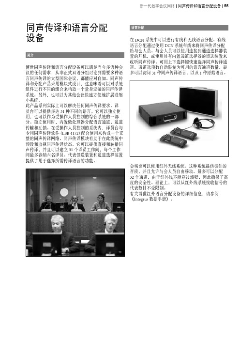
红外同声传译系统BOSCH(博世) 红外同声传译系统同声传译和语言分配设备新一代 DCN 系统结合了完善的同声传译和语言分配功能,从而满足多语种会议的要求。
所有同声传译功能都纳入基本系统概念,并且同声传译功能与所有其他系统功能使用相同的数字主干线路。
这可以比较方便地将语言功能集成到现有的新一代 DCN 系统中。
同声传译系统采用直接和自动转播两种同声传译模式,从而满足一些陌生语言的要求。
每个译员台都安装了用于普通(主要)语言的输出和用于其他次要语言的输出。
多达 31 种不同的语言新一代 DCN 译员台可以提供多达 31 个语言通道和 1个原始语言通道,所有通道的音频带宽均为 20 kHz。
每个译员工作间最多可以容纳六张译员台。
译员台可以独立使用,也可以作为系统的一部分使用。
当独立使用时,可以手动对其内置微处理器进行编程,从而分配语言通道、通道传输和互锁。
在受操作人员控制的系统中,译员台通过专用的软件(同声传译模块LBB 4172/00)来全面整合同声传译网络。
有线或无线语言分配新一代 DCN 提供了语言分配选项。
用户可以通过新一代 DCN 系统布线来实现语言分配,并且可用通道选择器装置或具有内置通道选择功能的代表装置来访问和选择语言。
适用于有线语言分配的通道选择器3 2 种语言。
IR 数字技术实现了高达 80 dB 的信噪比,确保提供最佳的音质。
Integrus 还可采用特殊的操作模式来耦合多个会议室。
这意味着位于各个房间中的多个系统可以提供完全相同的语言。
有关 Integrus 的详细信息,请参阅《Integrus 数据手册》。
北京傲德迅科技有限公司作为博世会议系统中国区代理商,将全力以赴为中国的经销商和用户提供最完美的系统解决方案和产品销售服务工作。
博世同传操作说明手册
博世操作说明1、数字会议系统操作说明系统简介会议发言系统采用DCN系统模块化的设计,根据不同的需求配备相应的功能模块,设计、实施与使用灵活。
可以达到发言的效果。
中央控制器(CCU)系统上电在中央控制器上设定话筒工作状态为“OPEN”——“OPEN”:话筒键控制,申请发言。
——“OVERRIED”:话筒键控制,越权发言。
——“VOICE”:声控启动话筒。
在中央控制器上设定话筒同时启动用数量为“1”——“1”:同时启动用1个话筒。
——“2”:同时启动用2个话筒。
——“4”:同时启动用4个话筒。
打开第一个话筒讲话。
此时该代表机扬声器关闭。
调节中央控制器音量控制旋钮。
调节中央控制器高、低音音调旋钮。
持续按下主席机优先控制键(蓝色键),可暂时关闭所有话筒,此时只有主席机可以发言。
松开此键,恢复原先的话筒状态。
在“OPEN”状态下(申请状态)●最多可同时打开的代表机数量为设定的话筒同时启用数量。
●已打开的话筒红色“光环”指示器亮,话筒键LED指示器为红色。
●后按键的代表机处于等待申请状态,话筒键LED指示器为绿色。
●当关闭一个打开的话筒时,首先处于申请状态的代表机自动打开。
以申请的时间先后顺序为准。
*建议:使用该状态,可靠且方便。
在“OVERRIDE”状态下(越权状态)●最多可同时打开的代表机数量为设定的话筒同时启用数量。
●已打开的话筒红色“光环”指示器亮,话筒键LED指示器为红色。
●后按键的代表机将直接打开,同时关闭第一个打开的话筒,以话筒打开的时间先后顺序为准。
在“VOICE”状态下(声控状态)●最多可同时打开的代表机数量为设定的话筒同时启用数量。
●所有话筒处于等待状态,各类指示器不起作用。
●当有发言时,自动打开当前话筒。
当发言结束,话筒自动恢复成等待状态。
*建议:不要使用该状态,以免产生不必要的麻烦。
2、同声传译设备操作说明(1)红外发射机打开设备电源(注意:此电源在设备的后面)。
把所有的通道全部打开(此时的四个小液晶显示屏上自上而下分别显示——0,1,2,3)。
BOSCH红外同传说明书 INT I&O ENG

INTEGRUSDIGITAL INFRA-RED LANGUAGE DISTRIBUTION SYSTEMInstallation and Operating ManualBOSCH2 | en INTEGRUS | Digital Infra-red Language Distribution System© 2003 BOSCH Security Systems GmbHBOSCH Security Systems B.V.| February 2003INTEGRUS | Digital Infra-red Language Distribution System en | 3BOSCH Security Systems | February 2003Table of contents1 System description and planning...............................................................................................................................5 1.1 System overview..........................................................................................................................................................................................5 1.2 System technology (7)1.2.1 IR radiation......................................................................................................................................................................................7 1.2.2 Signal Processing............................................................................................................................................................................7 1.2.3 Quality modes.................................................................................................................................................................................8 1.2.4 Carriers and channels.....................................................................................................................................................................8 1.3 Aspects of infra-red distribution systems (9)1.3.1 Directional sensitivity of the receiver.........................................................................................................................................9 1.3.2 The footprint of the radiator........................................................................................................................................................9 1.3.3 Ambient lighting...........................................................................................................................................................................10 1.3.4 Objects, surfaces and reflections...............................................................................................................................................10 1.3.5 Positioning the radiators.............................................................................................................................................................11 1.3.6 Overlapping footprints and multipath effects.........................................................................................................................13 1.4 Planning an Integrus infra-red radiation system. (13)1.4.1 Rectangular footprints.................................................................................................................................................................13 1.4.2 Planning radiators.........................................................................................................................................................................14 1.4.3 Cabling 151.5 Setting the radiator delay switches (16)1.5.1 System with one transmitter (16)1.5.1.1 Determining delay switch positions by measuring the cable lengths.................................................................16 1.5.1.2 Determining delay switch positions by using a delay measuring tool................................................................17 1.5.2 System with two or more transmitters in one room..............................................................................................................18 1.5.3 System with more than 4 carriers and a radiator under a balcony.......................................................................................20 1.6 Testing the coverage area.........................................................................................................................................................................21 2 Infra-Red Transmitters (LBB 4502/xx)...................................................................................................................22 2.1 Description.................................................................................................................................................................................................22 2.2 Audio interface modules.. (24)2.2.1 DCN Interface Module (LBB 3423/00)..................................................................................................................................24 2.2.2 Mounting an interface module in the transmitter housing...................................................................................................25 2.3 Connections (27)2.3.1 Connecting the DCN system.....................................................................................................................................................27 2.3.2 Connecting other external audio sources.................................................................................................................................28 2.3.3 Connecting an emergency signal...............................................................................................................................................29 2.3.4 Connecting to another transmitter............................................................................................................................................30 2.4 Using the configuration menu. (31)2.4.1 Overview........................................................................................................................................................................................31 2.4.2 Navigate through the menu........................................................................................................................................................32 2.4.3 Examples........................................................................................................................................................................................33 2.5 Configuration and operation. (36)2.5.1 Start-up 362.5.2 Main menu.....................................................................................................................................................................................36 2.5.3 View transmitter status................................................................................................................................................................36 2.5.4 View fault status...........................................................................................................................................................................37 2.5.5 Set monitoring options................................................................................................................................................................37 2.5.6 View version information...........................................................................................................................................................37 2.5.7 Set transmission mode.................................................................................................................................................................38 2.5.8 Set number of channels...............................................................................................................................................................38 2.5.9 Set channel quality and assign inputs to channels (38)4 | en INTEGRUS | Digital Infra-red Language Distribution SystemBOSCH Security Systems B.V.| February 20032.5.10 Set channel names........................................................................................................................................................................39 2.5.11 Disable or enable carriers............................................................................................................................................................40 2.5.12 View carrier assignments.............................................................................................................................................................40 2.5.13 Configure auxiliary inputs...........................................................................................................................................................41 2.5.14 Set sensitivity of the inputs.........................................................................................................................................................41 2.5.15 Choose transmitter name............................................................................................................................................................41 2.5.16 Enable / disable IR-monitoring................................................................................................................................................42 2.5.17 Enable / disable headphone output.........................................................................................................................................42 2.5.18 Reset all options to factory default values...............................................................................................................................42 3 Infra-red Radiators (LBB 4511/00 and LBB 4512/00)..............................................................................................43 3.1 Description.................................................................................................................................................................................................43 3.2 Radiator status indication.........................................................................................................................................................................44 3.3 Mounting the radiators.............................................................................................................................................................................44 3.4 Connecting radiators to the transmitter................................................................................................................................................47 3.5 Using the output power selection switch..............................................................................................................................................47 4 Infra-Red Receivers (LBB 4540/xx).........................................................................................................................48 4.1 Description.................................................................................................................................................................................................48 4.2 Operation....................................................................................................................................................................................................49 4.3 Reception test mode.................................................................................................................................................................................49 4.4 Receiver headphones................................................................................................................................................................................49 5 Charging Units (LBB 4560/xx)................................................................................................................................50 5.1 Description.................................................................................................................................................................................................50 5.2 Wall mounting the charging cabinet......................................................................................................................................................51 5.3 Charging procedure...................................................................................................................................................................................51 6 Troubleshooting.......................................................................................................................................................52 7 Technical Data.........................................................................................................................................................53 7.1 System Specification.................................................................................................................................................................................53 7.2 Transmitters and Modules.. (54)7.2.1 LBB 4502/xx Infra Red Transmitters......................................................................................................................................54 7.2.2 LBB 3423/00 DCN Interface Module.....................................................................................................................................54 7.3 Radiators and Accessories (55)7.3.1 LBB 4511/00 and LBB 4512/00 Radiators.............................................................................................................................55 7.3.2 LBB 3414/00 Wall Mounting Bracket.....................................................................................................................................55 7.4 Receivers, Battery Packs and Charging Units (56)7.4.1 LBB 4540 Pocket Receivers.......................................................................................................................................................56 7.4.2 LBB 4550/00 NiMH Battery Pack...........................................................................................................................................56 7.4.3 LBB 4560 Charging Units...........................................................................................................................................................56 7.5 Connection details. (57)7.5.1 Mains cables..................................................................................................................................................................................57 7.5.2 Audio cables..................................................................................................................................................................................57 7.5.3 Earphones......................................................................................................................................................................................57 7.5.4 Emergency switch........................................................................................................................................................................57 7.6 Guaranteed rectangular footprints.........................................................................................................................................................58 Product index . (60)INTEGRUS | Digital Infra-red Language Distribution System en | 5BOSCH Security Systems | February 20031 System description and planning1.1 System overviewIntegrus is a system for wireless distribution of audio signals via infra-red radiation. It can be used in a simultaneousinterpretation system for international conferences where multiple languages are used. To enable all participants to understand the proceedings, interpreters simultaneously translate the speaker’s language as required. These interpretations are distributed throughout the conference venue, and delegates select the language of their choice and listen to it through headphones. The Integrus system can also be used for music distribution (mono as well as stereo).Figure 1.1 Integrus system overview (with DCN-system as input)The Integrus Digital Infra-red Language Distribution System comprises one or more of the following: Infra-red transmitterThe transmitter is the core of the Integrus system. Four types are available: N LBB 4502/04 with inputs for 4 audio channels N LBB 4502/08 with inputs for 8 audio channels N LBB 4502/16 with inputs for 16 audio channels N LBB 4502/32 with inputs for 32 audio channelsInterface modulesOne of two different interface modules can be mounted in the transmitter housing to connect the transmitter to a wide range of conference systems:N LBB 3423 DCN Interface module to connect to the Digital Congress Network (DCN).N LBB 3422/1x Symmetrical Audio Input and Interpreters Module to connect to analogue discussion and conferencesystems (such as CCS 800) or to LBB 3222/04 6-channel interpreters desks. Infra-red radiatorsTwo types of radiators are available:N LBB 4511/00 medium-power radiator for small/medium conference venues N LBB 4512/00 high-power radiator for medium/large conference venuesBoth types can be switched between full and half power use. They can be mounted on walls, ceilings or floor stands.6 | en INTEGRUS | Digital Infra-red Language Distribution SystemBOSCH Security Systems B.V.| February 2003Infra-red receiversTwo multi-channel infra-red receivers are available: N LBB 4540/04 for 4 audio channels N LBB 4540/32 for 32 audio channelsThey can operate with a rechargeable NiMH battery pack or with disposable batteries. Charging circuitry is incorporated in the receiver.Charging equipmentEquipment is available for charging and storing 56 infra-red receivers. It is available for portable or fixed-installation applications.INTEGRUS | Digital Infra-red Language Distribution Systemen | 7BOSCH Security Systems | February 20031.2 System technology1.2.1 IR radiationThe Integrus system is based on transmission by modulated infra-red radiation. Infra-red radiation forms part of the electro-magnetic spectrum, which is composed of visible light, radio waves and other types of radiation. It has a wavelength just above that of visible light. Like visible light, it is reflected from hard surfaces, yet passes through translucent materials such as glass. The infra-red radiation spectrum in relation to other relevant spectra is shown in Figure 1.2.4005006007008009001000 nmFigure 1.2 Infra-red radiation spectrum in relation to other spectra1 Daylight spectrum2 Sensitivity of the human eye3 IR radiator4 Sensitivity of IR sensor5 Sensitivity of IR sensor withdaylight filter1.2.2 Signal ProcessingThe Integrus system uses high frequency carrier signals (typically 2-8 MHz) to prevent interference problems with modern light sources (see section 1.3.2). The digital audio processing guarantees an constant high audio quality.The signal processing in the transmitter consists of the following main steps (see Figure 1.3): 1. A/D conversion -Each analogue audio channel is converted to a digital signal.2. Compression - The digital signals are compressed to increase the amount of information that can be distributed on eachcarrier. The compression factor is also related to the required audio quality.3. Protocol Creation - Groups of up to four digital signals are combined into a digital information stream. Extra faultalgorithm information is added. This information is used by the receivers for fault detection and correction. 4. Modulation - A high frequency carrier signal is phase-modulated with the digital information stream.5. Radiation – Up to 8 modulated carrier signals are combined and sent to the IR radiators, which convert the carrier signalsto modulated infra-red light.In the IR receivers a reverse processing is used to convert the modulated infra-red light to separate analogue audio channels.Figure 1.3 Overview of the signal processing (for one carrier)8 | en INTEGRUS | Digital Infra-red Language Distribution SystemBOSCH Security Systems B.V.| February 20031.2.3 Quality modesThe Integrus system can transmit audio in four different quality modes: N Mono, standard quality, maximum 32 channels N Mono, premium quality, maximum 16 channels N Stereo, standard quality, maximum 16 channels N Stereo, premium quality, maximum 8 channelsThe standard quality mode uses less bandwidth and can be used for transmitting speech. For music the premium quality mode gives near CD quality.1.2.4 Carriers and channelsThe Integrus system can transmit up to 8 different carrier signals (depending on the transmitter type). Each carrier can contain up to 4 different audio channels. The maximum number of channels per carrier is dependent on the selected quality modes. Stereo signals use twice as much bandwidth as a mono signals, premium quality uses twice as much bandwidth as standard quality.Per carrier a mix of channels with different quality modes is possible, as long as the total available bandwidth is not exceeded. The table below lists all possible channel combinations per carrier:Channel qualityMono Standard Mono Premium Stereo Standard StereoPremium Bandwidth 4 4 x 10 kHz 2 1 2 x 10 kHz and 1 x 20 kHz2 1 2 x 10 kHz and 1 x 10 kHz (left) and 1 x 10 kHz (right)1 1 1 x 20 kHz and 1 x 10 kHz (left) and 1 x 10 kHz (right)2 2 x 10 kHz (left) and 2 x 10 kHz (right) 2 2 x 20 kHz Possiblenumber ofchannelsper carrier1 1 x 20 kHz (left) and 1 x 20 kHz (right)INTEGRUS | Digital Infra-red Language Distribution Systemen | 9BOSCH Security Systems | February 20031.3 Aspects of infra-red distribution systemsA good infra-red distribution system ensures that all delegates in a conference venue receive the distributed signals without disturbance. This is achieved by using enough radiators, placed at well planned positions, so that the conference venue is covered with uniform IR-radiation of adequate strength.There are several aspects that influence the uniformity and quality of the infra-red signal, which must be considered when planning an infra-red radiation distribution system. These are discussed in the next sections.1.3.1 Directional sensitivity of the receiverThe sensitivity of a receiver is at its best when it is aimed directly towards a radiator. The axis of maximum sensitivity is tilted upwards at an angle of 45 degrees (see Figure 1.4). Rotating the receiver will decrease the sensitivity. For rotations of less than +/- 45 degrees this effect is not large, but for larger rotations the sensitivity will decrease rapidly..Figure 1.4 Directional characteristics of the receivers1.3.2 The footprint of the radiatorThe coverage area of a radiator depends on the number of transmitted carriers and the output power of the radiator. The coverage area of the LBB 4512 radiator is twice as large as the coverage area of the LBB 4511. The coverage area can also be doubled by mounting two radiators side by side. The total radiation energy of a radiator is distributed over the transmitted carriers. When more carriers are used, the coverage area gets proportionally smaller. The receiver requires a strength of the IR signal of 4 mW/m2 per carrier to work without errors (resulting in a 80 dB S/N ratio for the audio channels). The effect of the number of carriers on the coverage area can be seen in Figure 1.5 and Figure 1.6. The radiation pattern is the area within which the radiation intensity is at least the minimum required signal strength.2004006008002Figure 1.5 Total coverage area of LBB 4511/00 and LBB 4512/00 for 1 to 8 carriers10 | en INTEGRUS | Digital Infra-red Language Distribution SystemBOSCH Security Systems B.V.| February 2003Figure 1.6 Polar diagram of the radiation pattern for 1, 2, 4 and 8 carriersThe cross section of the 3-dimensional radiation pattern with the floor of the conference venue is known as the footprint (the white area in Figure 1.7 to Figure 1.9). This is the floor area in which the direct signal is strong enough to ensure properreception, when the receiver is directed towards the radiator. As shown, the size and position of the footprint depends on the mounting height and angle of the radiator.Figure 1.7 The radiator mounted at 15G to the ceilingFigure 1.8 The radiator mounted at 45G to the ceilingFigure 1.9 The radiator mounted perpendicular (at 90G ) to the ceiling1.3.3 Ambient lightingThe Integrus system is practically immune for the effect of ambient lighting. Fluorescent lamps (with or without electronic ballast or dimming facility), such as TL lamps or energy saving lamps give no problems with the Integrus system. Also sunlight and artificial lighting with incandescent or halogen lamps up to 1000 lux give no problems with the Integrus system.When high levels of artificial lighting with incandescent or halogen lamps, such as spotlights or stage lighting are applied, you should directly point a radiator at the receivers in order to ensure reliable transmission.For venues containing large, unscreened windows, you must plan on using additional radiators.For events taking place in the open air a site test will be required in order to determine the required amount of radiators. With sufficient radiators installed, the receivers will work without errors, even in bright sunlight.1.3.4 Objects, surfaces and reflectionsThe presence of objects in a conference venue can influence the distribution of infra-red light. The texture and colour of the objects, walls and ceilings also plays an important role.Infra-red radiation is reflected from almost all surfaces. As is the case with visible light, smooth, bright or shiny surfaces reflect well. Dark or rough surfaces absorb large proportions of the infra-red signal (see Figure 1.10). With few exceptions it cannot pass through materials that are opaque to visible light.BOSCH Security Systems | February 2003Figure 1.10 The texture of the material determines how much light is reflected and how much is absorbedProblems caused by shadows from walls or furniture can be solved by ensuring that there are sufficient radiators and that they are well positioned, so that a strong enough infra-red field is produced over the whole conference area. Care should be taken not to direct radiators towards uncovered windows, as most of this radiation will subsequently be lost.1.3.5 Positioning the radiatorsSince infra-red radiation can reach a receiver directly and/or via diffused reflections, it is important to take this into account when considering the positioning of the radiators. Though it is best if receivers pick up direct path infra-red radiation,reflections improve the signal reception and should therefore not be minimised. Radiators should be positioned high enough not to be blocked by people in the hall (see Figure 1.11 and Figure 1.12).Figure 1.11 Infra-red signal blocked by a person in front of theparticipantFigure 1.12 Infra-red signal not blocked by a person in front of the participantThe figures below illustrate how infra-red radiation can be directed to conference participants. In Figure 1.14, the participant is situated clear from obstacles and walls, so a combination of direct and diffused radiation can be received. Figure 1.13shows the signal being reflected from a number of surfaces to the participant.BOSCH Security Systems B.V.| February 2003Figure 1.13 Combination of direct and reflected radiation Figure 1.14 Combination of several reflected signalsFor concentrically arranged conference rooms, centrally placed, angled radiators located high up can cover the area very efficiently. In rooms with few or no reflecting surfaces, such as a darkened film-projection room, the audience should be covered by direct path infra-red radiation from radiators positioned in front. When the direction of the receiver changes, e.g. with varying seat arrangements, mount the radiators in the corners of the room (see Figure 1.15).If the audience is always directed towards the radiators, you do not need radiators at the back (see Figure 1.16).If the path of the infra-red signals is partially blocked, e.g. under balconies, you should cover the ‘shaded’ area with an additional radiator (see Figure 1.17).The figures below illustrate the positioning of the radiators:arrangement auditorium seating and podium。
同声传译和语言分配 设备 说明书
同声传译和语言分配设备博世同声传译和语言分配设备可以满足当今多语种会议的任何需求,从非正式双语分组讨论到需要多种语言同声传译的大型国际会议,都能应对自如。
同声传译和分配产品采用模块式设计,这意味着可以对系统组件进行不同的组合来构造一个量身定做的同声传译系统。
另外,也可以为其他会议快速方便地扩展或缩小系统。
此产品系列实际上可以解决任何同声传译要求。
译员台可以提供多达 31 种不同的语言,它可以独立使用,也可以作为受操作人员控制的综合系统的一部分。
独立使用时,内置微处理器分配语言通道、通道传输和互锁。
在受操作人员控制的系统内,译员台与专用同声传译软件 (LBB 4172) 配合使用来构成一个完整的同声传译网络。
同声传译模块有助于在此类统中预设和监视同声传译状态。
它可以提供直接和转播同声传译,并且可以建立 31 个译员工作间,每个工作间最多容纳六名译员。
代表馈送装置和通道选择装置提供了用于选择所需传译语言的功能。
在 DCN 系统中可以进行有线和无线语言分配。
有线语言分配通过使用 DCN 系统布线来将同声传译分配给与会人员。
与会人员可以使用连接到通道选择器装置的耳机,或使用具有内置通道选择器的馈送装置来收听同声传译。
可用上下选择键快速选择同声传译通道。
通道选项数自动限制为可用的语言通道数量。
最多可以访问 31 种同声传译语言,以及 1 种原始语言。
会场也可以使用红外无线系统。
这种系统提供极佳的音质,并且允许与会人员自由移动。
最多可以分配32 个通道,由于红外线不能穿过墙壁,因此确保了高度的安全性。
理论上,可以从红外线系统接收信号的代表数目不受限制。
有关博世红外语言分配设备的详细信息,请参阅《Integrus 数据手册》。
新一代数字会议网络 | 同声传译和语言分配设备 |55DCN-IDESK 译员台可供一位译员使用,造型时尚,设计精美。
它完全符合国际通用标准。
译员台上的控件依据功能区进行清晰明确的布局,直观易用,避免出错。
BOSCH同声传译系统

BOSCH同声传译系统一、基本型拓扑图二、主要设备介绍1、D C N-C C U2基本中央控制装置中央控制装置(CCU) 具有以下功能:控制代表话筒、分配同声传译和引导投票进程,所有这一切都无需操作人员干预。
特性和优点• IF 设计大奖•控制多达245个馈送装置•可以控制数量不限的DCN-FCS 32 通道选择器• 2 x 32个高品质音频通道•基本话筒管理功能•三种操作话筒模式:•打开:话筒按钮控制发言请求(自动)•覆盖:通过话筒按钮可以覆盖已激活的话筒•语音:语音激活话筒•打开话筒的数量为1 至4个•用于代表大会投票程序的基本投票控制。
代表可以登记“出席”、“赞成”、“反对”和“弃权”。
Concentus 主席装置可以启动、停止和暂停投票。
合计结果可以显示在大厅显示屏和装置的LCD 屏幕上。
此外还包含传呼功能,用于激活投票音。
主席可以使用此声调来表示即将开始一轮投票。
•基本同声传译功能,附带31个语言通道以及1个原始语言通道•基本内部通信功能,可以指定内部通信操作人员和内部通信主席(都可以通过译员台呼叫)•自动摄像机控制• 2 路音频线路输入和2 路音频线路输出•可调节音频输入的灵敏度•可调节音频输出的灵敏度•音频插入功能,用于连接外部音频处理设备或电话耦合器•可通过显示屏和单个旋钮对CCU 和系统进行配置•安装人员可为每个CCU 分配唯一的名称以便识别•通过VU 计量表读数来监控音频输入和音频输出。
可以使用耳机来监控音频•适用于桌面或机架安装的19英寸(2U) 壳体•方便携带的提手•附带19 英寸机架安装支架、可拆卸支脚和安装附件•系统安装和用户手册光盘控件和指示灯前面•电源开关• 2 x 16 字符的 LCD 显示屏,用于显示状态和配置•旋钮,用于浏览菜单背面•三个红色 LED 过载指示灯,用于指示 DCN 网络输出•绿色和黄色 LED 指示灯,用于指示以太网活动互连前面•一个 3.5 毫米(0.14 英寸)立体声耳机插孔背面•内置保险丝的欧式电源插座•三个 DCN 电源插座,包括用于连接装置的锁定设施•两个立体声莲花插非均衡音频线路输入•一个 3 针 XLR 平衡式音频线路输出•两个立体声莲花插非均衡音频线路输出•一个以太网连接,用于控制 PC 或开放式接口•一个 RS‑232 串行数据连接器,用于控制摄像机技术指标电压 100‑240 Vac 50‑60 Hz功耗 295 WDCN 系统电源 40 Vdc,每个 DCN 插孔最高 85 W总功率 255 WRS-232 连接九针迷你D 凹型插孔频响 30 Hz –20 kHz(-3dB ,额定电平)额定电平时THD < 0.5 %串扰衰减 > 85 dB,1 kHz动态范围 > 90 dB信噪比 > 87 dBA音频输入莲花插额定输入 24 dBV (+/-6dB)莲花插最大输入 +0 dBV音频输出XLR 额定输出 12 dBV (+6/-24 dB)XLR 最大输出 +12 dBV莲花插额定输出 24 dBV (+6/-24 dB)莲花插最大输出 +0 dBV机械安装独立使用或安装在19 英寸支架中尺寸(高x 宽x 厚)88 x 483 x 350 毫米(含支架,不含支脚)92 x 440 x 350 毫米(不含支架,含支脚)重量 7 千克(15.4 磅)颜色碳灰色(PH 10736) 和银白色2、具有固定话筒的D C N-D I S S/D C N-D I S L讨论装置具有固定话筒的讨论装置可以使与会人员发言、登记发言请求以及听取他人发言。
BOSCH同声传译系统
BOSCH同声传译系统一、基本型拓扑图二、主要设备介绍1、D C N-C C U2基本中央控制装置中央控制装置(CCU) 具有以下功能:控制代表话筒、分配同声传译和引导投票进程,所有这一切都无需操作人员干预。
特性和优点? IF 设计大奖? 控制多达245个馈送装置? 可以控制数量不限的DCN-FCS 32 通道选择器? 2 x 32个高品质音频通道? 基本话筒管理功能? 三种操作话筒模式:? 打开:话筒按钮控制发言请求(自动)? 覆盖:通过话筒按钮可以覆盖已激活的话筒? 语音:语音激活话筒? 打开话筒的数量为1 至4个? 用于代表大会投票程序的基本投票控制。
代表可以登记“出席”、“赞成”、“反对”和“弃权”。
Concentus 主席装置可以启动、停止和暂停投票。
合计结果可以显示在大厅显示屏和装置的LCD 屏幕上。
此外还包含传呼功能,用于激活投票音。
主席可以使用此声调来表示即将开始一轮投票。
? 基本同声传译功能,附带31个语言通道以及1个原始语言通道? 基本内部通信功能,可以指定内部通信操作人员和内部通信主席(都可以通过译员台呼叫)? 自动摄像机控制? 2 路音频线路输入和2 路音频线路输出? 可调节音频输入的灵敏度? 可调节音频输出的灵敏度? 音频插入功能,用于连接外部音频处理设备或电话耦合器? 可通过显示屏和单个旋钮对CCU 和系统进行配置? 安装人员可为每个CCU 分配唯一的名称以便识别? 通过VU 计量表读数来监控音频输入和音频输出。
可以使用耳机来监控音频? 适用于桌面或机架安装的19英寸(2U) 壳体? 方便携带的提手? 附带19 英寸机架安装支架、可拆卸支脚和安装附件? 系统安装和用户手册光盘控件和指示灯前面? 电源开关? 2 x 16 字符的 LCD 显示屏,用于显示状态和配置? 旋钮,用于浏览菜单背面? 三个红色 LED 过载指示灯,用于指示 DCN 网络输出? 绿色和黄色 LED 指示灯,用于指示以太网活动互连前面? 一个 3.5 毫米(0.14 英寸)立体声耳机插孔背面? 内置保险丝的欧式电源插座? 三个 DCN 电源插座,包括用于连接装置的锁定设施? 两个立体声莲花插非均衡音频线路输入? 一个 3 针 XLR 平衡式音频线路输出? 两个立体声莲花插非均衡音频线路输出? 一个以太网连接,用于控制PC 或开放式接口? 一个RS?232 串行数据连接器,用于控制摄像机技术指标电压 100?240 Vac 50?60 Hz功耗 295 WDCN 系统电源 40 Vdc,每个 DCN 插孔最高 85 W总功率 255 WRS-232 连接九针迷你D 凹型插孔频响 30 Hz –20 kHz(-3dB ,额定电平)额定电平时THD < 0.5 %串扰衰减 > 85 dB,1 kHz动态范围 > 90 dB信噪比 > 87 dBA音频输入莲花插额定输入 24 dBV (+/-6dB)莲花插最大输入 +0 dBV音频输出XLR 额定输出 12 dBV (+6/-24 dB)XLR 最大输出 +12 dBV莲花插额定输出 24 dBV (+6/-24 dB)莲花插最大输出 +0 dBV机械安装独立使用或安装在19 英寸支架中尺寸(高x 宽x 厚)88 x 483 x 350 毫米(含支架,不含支脚)92 x 440 x 350 毫米(不含支架,含支脚)重量 7 千克(15.4 磅)颜色碳灰色(PH 10736) 和银白色2、具有固定话筒的D C N-D I S S/D C N-D I S L讨论装置具有固定话筒的讨论装置可以使与会人员发言、登记发言请求以及听取他人发言。
BOSCH同声传译系统方案
BOSCH同声传译系统方案
在使用BOSCH同声传译系统之前,需要进行一些准备工作。
首先,需要安装和配置发射器和接收器设备。
这些设备通常由专业工程师在会议现场安装,并与会议场地的音频系统相连接。
同传设备由翻译员使用,这些设备可以接收和传递多语言翻译。
翻译员可以通过耳麦听到发言者的内容,并将其翻译成指定语言通过发射器发送给与会者的接收器。
接收器上安装的耳机可以使与会者听到翻译内容,从而增加理解和参与度。
这个系统具有一些独特的功能和优势,使其成为同声传译的首选解决方案。
首先,BOSCH同声传译系统的音质非常清晰,没有杂音和干扰,确保与会者能够听到高质量的翻译内容。
其次,系统具有快速的响应时间,可以实时将发言内容翻译并传输给接收器。
此外,系统还支持多种语言模式和传输方式,提供高度的灵活性和可定制性。
总的来说,BOSCH同声传译系统是一种先进的多语言翻译解决方案,可以大大简化同声传译的过程,提高翻译的效率和质量。
无论是大型会议还是小型研讨会,这个系统都可以满足与会者和翻译员的需求,确保沟通和合作的顺畅进行。
博世同声传译 技术指标
博世同声传译技术指标博世同声传译技术指标随着全球化的不断推进,跨语言沟通已成为各行各业的必备技能。
在这一背景下,博世同声传译技术应运而生,为各种国际会议、商务洽谈、学术交流等提供了高效便捷的解决方案。
本文将从技术指标的角度,介绍博世同声传译的相关特点和应用。
一、同声传译技术的基本原理博世同声传译技术是一种通过无线设备实现的实时语言转换技术。
它包括两个主要组成部分:同声传译设备和中控系统。
同声传译设备由翻译人员使用,包括耳麦、话筒和语言选择器。
中控系统由技术人员操作,用于控制翻译信号的传输和接收。
通过同声传译设备,翻译人员可以实时听到源语言的内容,并将其翻译成目标语言,然后通过中控系统传输到听众的耳机中。
二、博世同声传译技术的技术指标1. 多语言支持:博世同声传译技术可以支持多种语言的传输和接收,包括但不限于英语、法语、德语、西班牙语等。
这使得全球范围内的跨语言沟通变得更加便捷。
2. 实时性:博世同声传译技术具有极低的延迟,可以实现几乎无延迟的语言传输。
这为会议和交流活动提供了高效的语言转换服务,使得参与者能够实时理解和回应对方的讲话。
3. 高保真音质:博世同声传译技术采用先进的音频处理技术,保证了传输过程中音质的高保真和清晰度。
听众可以听到与源语言几乎一致的目标语言内容,提升了语言理解的准确性。
4. 可扩展性:博世同声传译技术支持大规模的会议活动,可以同时服务于上百甚至上千人的听众。
通过扩展设备和中控系统,可以轻松应对不同规模的活动需求。
5. 灵活性和便携性:博世同声传译设备小巧轻便,方便携带和使用。
翻译人员可以随时随地进行语言转换,无需受到场地限制。
三、博世同声传译技术的应用领域1. 国际会议:在各种国际会议中,博世同声传译技术提供了高效准确的语言转换服务,使得与会人员可以毫不费力地进行跨语言交流。
不同语言之间的障碍被有效地消除,促进了会议的顺利进行。
2. 商务洽谈:在国际商务洽谈中,博世同声传译技术为各方提供了即时的语言转换支持,使得商务合作变得更加便捷。
博世会议产品说明
世界第一款全数字化的会议系统 , 性能提高到空前水平 .............................. 4 通过用户友好的软件实现卓越的数字性能 . ........................................ 4 模块化的系统结构 . ............................................................ 4 设备系列 . .................................................................... 5 先进的音频耦合功能 . .......................................................... 5 卓越非凡的音质 . .............................................................. 5 降低安装成本 . ................................................................ 5 简单方便的布线 . .............................................................. 5 馈送设备 . .................................................................... 6 桌面或嵌入式安装 . ............................................................ 6 同声传译和语言分配设备 . ...................................................... 6 多达 31种不同的语言 ......................................................... 6 有线或无线语言分配 . .......................................................... 7 适用于有线语言分配的通道选择器 . .............................................. 7 中央控制设备 . ................................................................ 7 完全自动化的会议进程 . ........................................................ 7 操作人员通过 PC 进行控制 ..................................................... 7 应用程序软件 . ................................................................ 8 信息分配设备 . ................................................................ 8 信息和大厅显示屏 . ............................................................ 8 示例 1-讨论 ................................................................ 8 示例 2-电子投票 ............................................................ 9 示例 3-同声传译 ........................................................... 10 示例 4-通过操作人员控制的会议 ............................................. 11 示例 5-出席登记和访问控制 ................................................. 12 示例 6-视频显示屏 ......................................................... 13 示例 7-查看当前发言人 ..................................................... 14 示例 8-通过互联网跟随会议进程 ............................................. 15 示例 9-私人对话 ...........................................................16 示例 10-音频扩展和音频记录 ................................................ 17 馈送设备 . ................................................................... 18 具有固定话筒的 DCN-DISS/DCN-DISL讨论装置 ................................... 19 DCN-DISD 基本讨论装置 ....................................................... 21 具有通道选择器的 DCN-DISCS 讨论装置 . ......................................... 23 具有双通道选择器的 DCN-DISDCS 讨论装置 ...................................... 24 具有投票功能的 DCN-DISV 讨论装置 . ............................................ 26 具有投票功能和通道选择器的 DCN-DISVCS 讨论装置 ............................... 28 用于讨论装置的 DCN-DISR 装饰条 .............................................. 30 DCN-MICS/L可插拔短 /长柄话筒 ................................................ 30 用于主席讨论装置的 DCN-DISBCM 按钮 .......................................... 31 用于双重用途讨论装置的 DCN-DISBDD 按钮 ...................................... 31 用于讨论装置的 DCN-DISCLM 缆线夹(每套 25个 ............................... 32 用于讨论装置的 DCN-FCDIS 便携箱 ............................................. 32 C ONCENTUS 装置 (32)DCN-CON C ONCENTUS 装置 ........................................................ 33 具有通道选择器的 DCN-CONCS C ONCENTUS 装置 ..................................... 35 DCN-CONFF C ONCENTUS 全功能装置 . ............................................... 37 DCN-CONCM C ONCENTUS 主席装置 . ................................................. 39 用于 C ONCENTUS 装置的DCN-FCCON 便携箱 ........................................ 42 LBB 3555/00内部通信对讲机和支架 ............................................ 42 嵌入式安装的馈送装置 . ....................................................... 43 DCN-DDI 双代表接口 .......................................................... 44 DCN-FHH 手持式话筒 .......................................................... 46 DCN-FMIC 话筒连接面板 ....................................................... 47 DCN-FMICB 话筒控制面板 ...................................................... 47 DCN-FPRIOB 优先面板 ......................................................... 48 DCN-FLSP 扬声器面板 ......................................................... 49 DCN-FV 投票面板 ............................................................. 50 DCN-FVCRD 投票和插卡面板 .................................................... 51 DCN-FBP 空面板(每套 10个 ................................................. 51 DCN-FEC 端帽(每套 50个 ................................................... 52 DCN-FCOUP 接头(每套 50个 ................................................. 52 DCN-FPT 嵌入定位工具 ........................................................ 53 DCN-TTH 桌面壳体(每套 10个 ............................................... 53 DCN-FVU 投票装置 ............................................................ 53 DCN-FVU-CN 中文投票装置 ..................................................... 54 LBB 9600/20电容式单向话筒 .................................................. 55 LBC 1215/01话筒夹 .......................................................... 57 LBC 1221/01脚架 ............................................................ 57 LBC 1226/01可调式话筒吊杆 .................................................. 57 同声传译和语言分配设备 . ..................................................... 58 DCN-IDESK 译员台 ............................................................ 59 LBB 9095/30译员耳机 ........................................................ 61 用于 DCN-IDESK 和附件的 DCN-FCIDSK 便携箱 .................................... 61 DCN-FCS 通道选择器装置(32通道 ........................................... 62 LBB 3443/00轻便立体声耳机 .................................................. 62 LBB 3441/10颏下型立体声耳机 ................................................ 63 LBB 3442/00单耳机 .......................................................... 63 LBB 3015/04功能强大的动态耳机 .............................................. 64 中央控制设备 . ............................................................... 65 DCN-CCUB 基本中央控制装置 ................................................... 65 DCN-CCU 中央控制装置 ........................................................ 67 PRS-4DEX4数字音频扩展器 .................................................... 70 LBB 4402/00音频扩展器 ...................................................... 71 LBB 4404/00C OBRA N ET ™接口 .................................................... 73 LBB 1968/00斑丽反馈抑制器 .................................................. 74 LBB 4157/00ID 卡编码器 ..................................................... 77 LBB 4159/00ID 卡(每套 100张 (77)应用程序软件 . ............................................................... 77 DCN-SW PC 控制软件 .......................................................... 78 DCN-SWSI 系统安装模块 ....................................................... 78 DCN-SWMM 话筒管理模块 ....................................................... 79 DCN-SWSC 摘要式控制模块 ..................................................... 80 DCN-SWDB 代表数据库模块 ..................................................... 81 LBB 4190/00启动模块 ........................................................ 82 LBB 4170/00话筒管理模块 .................................................... 82 LBB 4171/00摘要式话筒管理模块 .............................................. 84 LBB 4172/00同声传译模块 .................................................... 85 LBB 4173/00内部通信模块 .................................................... 85 LBB 4175/00代表大会投票模块 ................................................ 86 LBB 4176/00多选投票模块 .................................................... 87 LBB 4178/00出席登记模块 .................................................... 88 LBB 4180/00代表数据库模块 .................................................. 89 LBB 4181/00ID 卡编码器模块 ................................................. 90 LBB 4182/00消息分配模块 .................................................... 90 LBB 4183/00文字 /状态显示模块 ............................................... 91 LBB 4184/00视频显示模块 .................................................... 92 LBB 4185/00系统安装模块 .................................................... 92 LBB 4162/00独立自动摄像机控制模块 .......................................... 93 LBB 4189/00新一代 DCN 多 PC 模块 ............................................ 94 LBB 4187/00开放式接口模块 .................................................. 94 信息显示 . ................................................................... 95 DCN-DDB 数据分发板 .......................................................... 96 摄像机和附件 . ............................................................... 97 LTC 8200A LLEGIANT 视频切换台 ................................................. 98 LTC 8555/00A LLEGIANT 键盘 .................................................... 99 LTC 5136/51A UTO D OME ®控制器 .................................................. 99 G3A 系列 A UTO D OME ®系统 ....................................................... 100 LTC 0455/10系列彩色摄像机 ................................................. 100 MON152CL LCD 监视器 ........................................................ 101 安装设备 . .................................................................. 102 DCN-EPS 扩展电源 ........................................................... 103 LBB 4114/00干线分路器 ..................................................... 103 LBB 4115/00分流装置 ....................................................... 104 LBB 4116DCN 安装电缆 ...................................................... 104 LBB 4117/00电缆锁定夹(每套 25个 ........................................ 105 LBB 4118/00电缆端部插头 ................................................... 105 LBB 4119/00DCN 连接器 ..................................................... 105 LBB 4410/00光纤网络分路器 ................................................. 105 LBB 4414/10无地址光纤接口 ................................................. 106 LBB 4416/XX100安装网络电缆 ............................................... 107 LBB 4419/00光纤电缆耦合器(每套 10个 (108)世界第一款全数字化的会议系统 , 性能提高到空前水平博世推出的新一代数字会议网络 (DCN 把创新数字技术的种种好处融入了讨论、会谈和会议系统。
- 1、下载文档前请自行甄别文档内容的完整性,平台不提供额外的编辑、内容补充、找答案等附加服务。
- 2、"仅部分预览"的文档,不可在线预览部分如存在完整性等问题,可反馈申请退款(可完整预览的文档不适用该条件!)。
- 3、如文档侵犯您的权益,请联系客服反馈,我们会尽快为您处理(人工客服工作时间:9:00-18:30)。
BOSCH 同声传译系统说明中央控制器通过置的D/A转换器,将会议系统的音频信号输入到混音功放进行扩声,并可将外部的声源信号通过中央控制器接入DCN 系统,代表可在面板扬声器和耳机中直接收听。
BOSCH(原PHILIPS)数字会议网络系统(DCN)首开在研讨、代表、大型国际会议中应用数字技术的先河,它的信号传输和处理均采用了数字音频技术,具有多功能、高音质、数据传输可靠等特点,可对会议过程实行全面的控制,对各类型的会议都能提供灵活的管理,不论是非正式的小型会议,还是上千人的国际大型会议。
DCN是同类设备中率先采用全数字技术的系统。
具有多功能、高音质、数据传送可靠等特点,可以满足现代会议的一切管理需求,包括:基本的话筒管理,代表认证和登记,电子表决,资料分配和显示以及多语种的同声传译。
系统的信号和处理采用了久经考验的飞利浦数字音频技术。
比如在会议代表用的话筒中采用了高性能的“Bitstream”系统进行模-数转换。
由于采用了先进的数字技术,在传输过程号的质量和幅度都不会衰减,因此音频的技术性能达到了空前的水平。
使得每一个与会者都可以听到稳定、纯正的声音。
这一点对提高发言的清晰度无疑有重要的贡献。
DCN从根本上消除了一般会议系统的缺陷,如背景噪音、干扰、失真和串音等。
DCN数字技术的另一个重要优点是安装速度快,节约经费。
用一根细而软的双同轴电缆可以传送系统的全部数字信号,并且可以在任意点上“搭接”补充发言机或其他DCN设备。
因此在以后需要将系统的容量进一步扩大时,不必改动系统原来的接线即可进行扩容。
各设备的电源也是同一根电缆上的两根线提供的。
DCN的控制系统有两种选择:一种是以先进的、操作方便的软件设施调整与控制。
另一种是无机务人员的自动控制。
系统的应用软件能把会议的准备、管理、控制置于计算机环境中,微软视窗允许同时运行多个软件,并可在各应用软件之间进行信息传递。
视窗的图形用户界面具有非常的直观性。
DNC系统就是利用这一点进行会议控制。
BOSCH LBB3547/00 主席机●带用于收听翻译声的声道选择器●带背光的LCD屏幕●五个表决键●置可折叠的平板扬声器●带主席优先按钮●安装在可弯曲支杆上的话筒带“光环”指示器●打开话筒或连通耳机时扬声器自动关闭●带耳机音量控制按钮技术指标:尺寸:50 x 275 x155(mm)话筒及安装表面长度:313mm重量:1.5公斤颜色:碳黑色,银盘面BOSCH LBB3544/00 代表机●带用于收听翻译声的声道选择器●五个表决键●置可折叠的平板扬声器●带话筒“开/请求发言”双色LED按钮●安装在可弯曲支杆上的话筒带“光环”指示器●打开话筒或连通耳机时扬声器自动关闭●带耳机音量控制按钮技术指标:尺寸:50 x 275 x 155(mm)重量:1.4公斤颜色:碳黑色,银盘面BOSCH LBB3500/05 会议中央控制器●无机务员的会议控制●控制多达240台发言设备●置的电源除了为本机供电外,还可向外部连接的DCN设备提供电源。
最多可以驱动90台发言设备●控制分配设备的数量不受限制。
●高质量的数字音频控制和处理,可以用于发言、传译、分配等●有三种工作模式:OPEN ——话筒键控制,有请求发言的登记功能OVERRIDE ——话筒键控制,在对正在运行的话筒越权运行(FIFO)VOICE ——声控启动话筒●对每种工作状态都可以选1、2和4个话筒同时启动●提供基本的表决功能,用它可以进行会议表决。
●基本的同声传译功能,最多11个翻译声道及发言原语种声道技术指标:尺寸:100 x 440 x 308(mm)重量:9.3公斤颜色:浅灰BOSCH LBB4502/08 红外线发射机发射机适合装入下9英寸的机架或置于桌面,有专用插槽,可以装入一个模块。
发射机是Integrus系统的核心设备。
它接受数字(来自DCN)或模拟的输入信号,并用这些信号调制载波,然后将调制的载波送到布置在房间中的辐射器上。
特点:●通用电源适合世界各地供电规格。
●可以分配的通道数最多为4、8、16或32音频通道。
●适合与DCN或模拟系统,如:CCS800配合使用。
●自动向所有音频通道发出紧急信息。
●在休息的时候,用辅助模式向所有通道播送音乐。
●灵活的通道配置和通道质量模式,可以提高分配效率。
●每个输入可以分别调整输入灵敏度,使输入电平得到精确调整。
●在测试模式下,为每个输入/通道产生不同频率的测试信号,随通道的提高,测试声调逐渐提高。
●可以将另一台发射机用“从动模式”分配信号,因此可以多房间使用。
●置小型红外辐射器用于音频的监听。
●辐射器和系统状态通过显示器指示。
●发射机和系统的配置,通过一个显示器和一个旋转按钮完成。
●安装人员可以为每台发射机指定一个名字,以便识别。
可以为每个音频通道分别指定一个名字,以便识别。
名字可以从一个表中选择,也可以手输。
●自动待机/运行功能。
●通道数量与DCN系统中正在使用的通道数量自动同步。
●19英寸(2U)机箱,可以装入机架或置于桌面。
●手柄方便搬运。
●包括了19英寸机架的安装板,可拆卸的底脚和安装附件。
控制和指示部分包括:● 2 x 16字符的LCD指示器,显示状态信息和发射机的配置旋转按钮用于浏览菜单和配置●正面盘上的电源开关BOSCH LBB3520/10 译员台●可适配15种语言包括本身的语种●用预置键选择语种●输入语言的质量指示●带照明的LCD显示屏可显示出清晰的资料●改进的人类工程学设计简化操作技术指标:尺寸:295 x 100(mm)重量:1公斤颜色:碳黑色BOSCH LBB4511/00 红外辐射板红外辐射器是大功率的红外辐射设备,适合用在大型场地。
通过个人接收机让代表们聆听会议的进行。
特点:●LBB4511覆盖可高达1000m2(一个载波,四个标准音质通道)●通用电源,适合全世界使用。
●不使用风扇——采用对流风冷却,安静运行,减少磨损零件的●有辐射器状态监测的LED指示。
●发射机与辐射器间的通讯,方便操作人员的检测。
●随发射机自动同步开机或关机。
●自动增益控制保证IRED(红外发光二极管)发挥最大效率。
●自动电缆均衡,保证用不同质量电缆时得到最高的传输效率。
●自动电缆终接,使安装简便。
●温控线路,辐射器升温过高时,自动由全功率切换到半功率。
●安装架,适合天花板和落地架安装。
●可调的辐射器角度,保证最大覆盖面积。
●红外发光二极管有涂层保护,因而辐射器容易维护和清洁。
●外形时尚大方。
控制和指示部分包括:●2个黄LED:每个辐射器盘上一个,指示本盘已接通电源并收到来自发射机的载波。
●2个红LED:每个辐射器盘上一个,指示本盘已接通电源并处于待机状态。
●红和黄LED同时亮,指示辐射器产生故障。
●红LED闪、黄LED亮,指示辐射器盘处于过热保护状态。
●减少功率开关,使辐射器输出功率减少一半。
●2个延时补偿开关,对发射机到辐射器之间电缆长度的不同进行有关技术指标红外发光二极管的数量: 260200c时总红外输出: 8Wrms l6Wpp总发光峰值强度: 9W/sr半值角: +/-220HF输入:标称1Vpp,最小10mVppHF输出 1Vpp,6VDC,75欧姆市电电压 90 - 260V,50Hz至60Hz电源功耗 1OOW待机的电源功耗 8W尺寸(高X宽X厚):200x 500 x 175mm(7.9x 19.7 x 6.9英寸)重量:(不包括架子) 6.8kg(15磅)(包括架子) 7.6kg(17磅)BOSCH LBB4540/04 4路红外线接收机按人体工程学设计的接收机,采用了最新的电子技术——包括专门设计的芯片——保证最好的性能和最长的电池寿命。
接收机适合接收语言和音乐。
特点:专门设计的芯片获得最佳性能和最长的电池寿命。
●2位数的LCD显示可以指示电池和接收的状态。
●同步功能:可用通道数量永远与系统中正在使用的通道数量一致。
没使用的通道不出现在可选择的通道中。
●当信号过低时,自动对音频信号静音,保证使用人只接收高质量信号。
●可以用一次性电池(2xAA硷性电池)供电,或环保的NiMH充电电池组(LBB4550/00)o●当断开耳机后,不再耗电。
●配有卡子,容易佩带。
●有测量模式,便于监测辐射器的覆盖。
●外形时尚大方。
●用碱性电池可运行高达200小时。
●用电池组可运行高达75小时。
●从无电到满电的充电时间是1小时45分钟。
控制和指示部分包括:●2位的LCD指示器,指示通道号、电池、和接收状态●开关按钮●滑杆式音量调节器●通道的正/逆选择按钮●充电的LED指示器接口● 3.5mm(0.14英寸)立体声耳机输出插口●AA碱性电池的接点●LBB4550电池组的插口●接收机左侧的充电接点,与LBB4560充电器兼容相关技术指标尺寸(宽 x 高 x 深): 155 x 45 x 30mm重量:(不计电池/电池盒) 75g(0.16磅)(包括电池/电池盒) 125g(0.27磅)外部装饰银黑色红外辐射强度每载波4mW/m2灵敏度半值角度 +/-500在2.4V时的耳机输出音量 450mVrms(以最大音量讲话,32欧姆耳机)耳机输出频响 20Hz - 20kHz阻抗 32欧姆至2k欧姆最大信噪比 80dB(A)电源电压 1.8至3.6V,标称2.4V电源功耗(2,4V电源) 15mA(最大音量讲话,32欧姆耳机)电源功耗(待机) <1m实用标准文案系统连接图:文档大全。