博世同传操作说明书
同传耳机领取通知及使用说明

语种选择键 LanБайду номын сангаасuage
红外接收面 Infrared Receiver
显示屏 Display 使用方法 一.正面银色开关键 二.选择接收听频道 0:原音 1:中文 2:英文 三.左侧推键调节音量 Usage Press the front silvercolored power button Select receiving channels 0:original voice 1:Chinese 2:English The push key on the left is for Volume control 耳机插孔 Earpieces
同声翻译设备领取处
由于本次活动嘉宾众多,请各位来宾持 个人有效身份证件(身份证、驾照、护 照、社保卡等)来领取同声翻译接收机 和耳机,并请妥善保管,离开会场时勿 忘换回证件,谢谢配合。
博世接收机使用说明(同声翻译) BOSCH Receiver Specification
音量键 Volume 开关键 Power on/off
博世 3 2 1 GS SERIES III 3 2 1 SERIES III 说明书

44 44 45 45
参考内容
59
更换遥控器电池 . . . . . . . . . . . . . . . . . . . . . . . . . . . . . 59 保护系统 . . . . . . . . . . . . . . . . . . . . . . . . . . . . . . . . . . 59 清洁媒体中心 . . . . . . . . . . . . . . . . . . . . . . . . . . . . . 59 清洁扬声器 . . . . . . . . . . . . . . . . . . . . . . . . . . . . . . . 59 故障诊断 . . . . . . . . . . . . . . . . . . . . . . . . . . . . . . . . . . 60 客户服务处 . . . . . . . . . . . . . . . . . . . . . . . . . . . . . . . . 63 有限质保 . . . . . . . . . . . . . . . . . . . . . . . . . . . . . . . . . . 63 技术信息 . . . . . . . . . . . . . . . . . . . . . . . . . . . . . . . . . . 64
2
2 3 4
首次使用
33
试用 DVD . . . . . . . . . . . . . . . . . . . . . . . . . . . . . . . . . 33
控件和指示器
34
安装
1 2 3 4 5 放置系统组件 . . . . . . . . . . . . . . . . . . . . . . . . . . . . . . 将扬声器连接到模块上 . . . . . . . . . . . . . . . . . . . . . . .
博世多功能料理机说明书.pdf_1699328773.1342912
https:///manual/8001209041[en]Scan the QR code or visit the website to open the Further Notices for Use. You can find additional informa-tion about your appliance or accessory here.[ms]Imbas kod QR atau lawati laman web untuk membuka arahan penggunaan lanjut. Anda boleh mendapatkan maklumat tambahan mengenai peranti anda atau aksesori di situ.[zh-tw]掃描 QR-Code 或訪問網站,以開啟更詳細的使用說明。
您可於此處找到有關電器或配件的更多資訊。
[zh]要打开更多与使用相关的提示,请扫描二维码或访问网站。
您可以在那里查阅关于机器或附件的更多详细信息。
[ar]حسمازمرةباجتسلااةعيرسلاايئوضوألَّضفتةرايزبعقوملاينورتكللإاحتفلتاداشرلإاةعسوملالوحمادختسلاا.دجتكانهتامولعمةيفاضإلوحكزاهجوأتاقحلملا.en Safety8Safety¡Observe the instructions for the base unit.Only use the accessories:¡with a hand blender MSM1..., MSM2..., MSM6B...¡for applications described in these instructions.▶Never touch the blade edges with bare hands.▶Care should be taken when handling sharp blades, emptying the container and during cleaning.▶Only attach and remove accessories once the drive has stopped and the appliance has been unplugged.▶Only use the accessories once fully assembled.Avoiding material damage▶Never immerse the gear attachments in liquids and do not clean under runningwater or in the dishwasher.▶Never use the universal cutter container in the microwave or oven.▶Never use the blender foot or the whisk in the universal cutter container. Overview→ Fig. 1Depending on the modelNote: If an item is not included in the scope of supply, it can be ordered from customer service.Universal cutterThe universal cutter is suitable for cutting up food, e.g. meat, hard cheese, onions, garlic, fruit, vegetables, herbs, nuts or al-monds.Notes¡Remove hard pieces of food before pro-cessing, e.g. gristle, bones, sinews orstones from stone fruit.¡The universal cutter is not suitable for cutting up very hard food, e.g. coffeebeans, nutmegs, radishes or frozen food,e.g. fruit or ice cubes.Using the universal cutter→ Fig. 2 - 11WhiskThe whisk is suitable for whipping cream, beating egg whites or milk froth and for making sauces or desserts. Recommendations for optimum results:¡Use cream with a minimum fat content of 30% and a temperature of 4-8 °C¡Use milk with a high protein content anda temperature of max. 8 °C¡Whip cream or beat egg whites in a wide jugNote: To prevent splashing, use deep con-tainers with the whisk.Application examples enUsing the whisk→ Fig. 12 - 16Application examplesAlways observe the maximum quantitiesand processing times in the table.→ Fig. 17Honey cake with applesHoney-apple mixture→ Fig. 18Cakes¡ 3 eggs¡60 g butter¡100 g plain white flour¡60 g ground walnuts¡ 1 tsp cinnamon¡ 2 tbsp vanilla sugar¡ 1 tsp baking powder¡ 1 applePreparation¡Separate the eggs and whisk the eggwhites until stiff.¡Beat the egg yolk with the sugar untillight and fluffy. Add the soft butter andthe prepared honey-apple mixture.¡Mix the rest of the ingredients in a separ-ate bowl, add to the moist ingredientsand stir in.¡Carefully fold in the beaten egg whiteswith a spatula.¡Line a rectangular loaf tin (35 x 11 cm)with greaseproof paper and add the pre-pared cake mixture.¡Peel the apple, cut into slices and ar-range on the cake.¡Preheat the oven to 180 °C and bakethe cake for 30 minutes.Overview of cleaningClean the individual parts as indicated inthe table.→ Fig. 199ms Keselamatan10Keselamatan¡Ikuti arahan untuk peranti asas.Gunakan aksesori hanya:¡dengan pengadun tangan MSM1..., MSM2..., MSM6B...¡untuk aplikasi yang dijelaskan dalam manual ini.▶Jangan sesekali menyentuh bilah dengan tangan.▶Berhati-hati semasa mengendalikan bilah pemotong yang tajam dan juga semasa mengosongkan bekas dan semasa pembersihan.▶Hanya pasang dan tanggalkan aksesori semasa pemacu berhenti dan peranti tidak terpasang.▶Gunakan aksesori hanya apabila dipasang sepenuhnya.Elakkan kerosakan harta benda ▶Jangan sekali-kali merendam unit gear dalam cecair dan jangan sekali-kalimembersihkannya di bawah air yangmengalir atau di mesin basuh pingganmangkuk.▶Jangan sekali-kali menggunakan bekas pencincang sejagat dalam ketuhargelombang mikro atau ketuhar.▶Jangan sekali-kali menggunakan kaki pengadun atau pukul ke dalam bekaspencincang sejagat.Gambaran keseluruhan→ Raj. 11Bergantung kepada model Nota: Sekiranya komponen tidak disertakan dalam skop penghantaran, anda boleh memesan melalui perkhidmatan pelanggan.Pemotong kecil universal Pemotong kecil universal sesuai untuk memotong kecil bahan makanan, cth. daging, keju keras, bawang besar, bawang putih, buah-buahan, sayur-sayuran, herba, kekacang atau badam.Nota¡Keluarkan objek keras dari bahan makanan sebelum pemprosesan, cth.rawan, tulang, urat atau biji dari buah.¡Pemotong kecil universal tidak sesuai untuk memotong kecil bahan makananyang sangat keras, cth. biji kopi, buahpala, lobak atau bahan makanan yangbeku, cth. buah atau kiub ais. Gunakan pemotong kecil universal→ Raj. 2 - 11Pemukul telurPemukul telur sesuai untuk memukul krim putar, putih telur atau buih susu dan untuk menyediakan sos atau pencuci mulut. Saranan untuk hasil yang optimum:¡Gunakan krim dengan kandungan lemak min. 30% dan 4-8 °CContoh penggunaan ms11¡Gunakan susu dengan kandunganprotein tinggi dan maks. 8 °C ¡Pukul krim atau putih telur di dalam bekas yang lebar Nota: Untuk mengelakkan percikan,gunakan pemukul telur dalam bekas yang tinggi.Gunakan pemukul telur→ Raj. 12 - 16Contoh penggunaanPerhatikan kuantiti maksimum dan masa pemprosesan dalam jadual.→ Raj. 17Kek madu dengan epal Campuran madu epal→ Raj. 18Kek¡ 3 biji telur¡60 g mentega¡100 g tepung putih (jenis 405)¡60 g walnut yang dikisar¡ 1 sudu teh kayu manis¡ 2 sudu besar gula vanila¡ 1 sudu teh serbuk penaik¡ 1 epalPenyediaan¡Pisahkan putih telur dengan kuning telurdan pukul putih telur sehingga kembang.¡Pukul kuning telur dengan gula hinggaberbuih. Tambahkan mentega lembutdan campuran madu epal yang telahdisediakan.¡Campurkan bahan yang lain di dalammangkuk yang berasingan untukmenambah dan mengacau bahanbasah.¡Kaup dan balikkan putih telur secaraberhati-hati dengan spatula.¡Alaskan loyang kek (35 x 11 cm)dengan kertas minyak dan masukkancampuran kek yang disediakan.¡Kupas epal, hiris dan tabur di atas kek.¡Panaskan ketuhar hingga 180 °C danbakar kek selama 30 minit.Gambaran keseluruhanpembersihanBersihkan bahagian-bahagian tunggal seperti yang ditunjukkan dalam jadual.→ Raj. 19zh-tw 安全性12安全性¡注意主機的說明書。
博世同传操作说明手册
博世操作说明1、数字会议系统操作说明系统简介会议发言系统采用DCN系统模块化的设计,根据不同的需求配备相应的功能模块,设计、实施与使用灵活。
可以达到发言的效果。
中央控制器(CCU)系统上电在中央控制器上设定话筒工作状态为“OPEN”——“OPEN”:话筒键控制,申请发言。
——“OVERRIED”:话筒键控制,越权发言。
——“VOICE”:声控启动话筒。
在中央控制器上设定话筒同时启动用数量为“1”——“1”:同时启动用1个话筒。
——“2”:同时启动用2个话筒。
——“4”:同时启动用4个话筒。
打开第一个话筒讲话。
此时该代表机扬声器关闭。
调节中央控制器音量控制旋钮。
调节中央控制器高、低音音调旋钮。
持续按下主席机优先控制键(蓝色键),可暂时关闭所有话筒,此时只有主席机可以发言。
松开此键,恢复原先的话筒状态。
在“OPEN”状态下(申请状态)●最多可同时打开的代表机数量为设定的话筒同时启用数量。
●已打开的话筒红色“光环”指示器亮,话筒键LED指示器为红色。
●后按键的代表机处于等待申请状态,话筒键LED指示器为绿色。
●当关闭一个打开的话筒时,首先处于申请状态的代表机自动打开。
以申请的时间先后顺序为准。
*建议:使用该状态,可靠且方便。
在“OVERRIDE”状态下(越权状态)●最多可同时打开的代表机数量为设定的话筒同时启用数量。
●已打开的话筒红色“光环”指示器亮,话筒键LED指示器为红色。
●后按键的代表机将直接打开,同时关闭第一个打开的话筒,以话筒打开的时间先后顺序为准。
在“VOICE”状态下(声控状态)●最多可同时打开的代表机数量为设定的话筒同时启用数量。
●所有话筒处于等待状态,各类指示器不起作用。
●当有发言时,自动打开当前话筒。
当发言结束,话筒自动恢复成等待状态。
*建议:不要使用该状态,以免产生不必要的麻烦。
2、同声传译设备操作说明(1)红外发射机打开设备电源(注意:此电源在设备的后面)。
把所有的通道全部打开(此时的四个小液晶显示屏上自上而下分别显示——0,1,2,3)。
BOSCH红外同传说明书 INT I&O ENG

INTEGRUSDIGITAL INFRA-RED LANGUAGE DISTRIBUTION SYSTEMInstallation and Operating ManualBOSCH2 | en INTEGRUS | Digital Infra-red Language Distribution System© 2003 BOSCH Security Systems GmbHBOSCH Security Systems B.V.| February 2003INTEGRUS | Digital Infra-red Language Distribution System en | 3BOSCH Security Systems | February 2003Table of contents1 System description and planning...............................................................................................................................5 1.1 System overview..........................................................................................................................................................................................5 1.2 System technology (7)1.2.1 IR radiation......................................................................................................................................................................................7 1.2.2 Signal Processing............................................................................................................................................................................7 1.2.3 Quality modes.................................................................................................................................................................................8 1.2.4 Carriers and channels.....................................................................................................................................................................8 1.3 Aspects of infra-red distribution systems (9)1.3.1 Directional sensitivity of the receiver.........................................................................................................................................9 1.3.2 The footprint of the radiator........................................................................................................................................................9 1.3.3 Ambient lighting...........................................................................................................................................................................10 1.3.4 Objects, surfaces and reflections...............................................................................................................................................10 1.3.5 Positioning the radiators.............................................................................................................................................................11 1.3.6 Overlapping footprints and multipath effects.........................................................................................................................13 1.4 Planning an Integrus infra-red radiation system. (13)1.4.1 Rectangular footprints.................................................................................................................................................................13 1.4.2 Planning radiators.........................................................................................................................................................................14 1.4.3 Cabling 151.5 Setting the radiator delay switches (16)1.5.1 System with one transmitter (16)1.5.1.1 Determining delay switch positions by measuring the cable lengths.................................................................16 1.5.1.2 Determining delay switch positions by using a delay measuring tool................................................................17 1.5.2 System with two or more transmitters in one room..............................................................................................................18 1.5.3 System with more than 4 carriers and a radiator under a balcony.......................................................................................20 1.6 Testing the coverage area.........................................................................................................................................................................21 2 Infra-Red Transmitters (LBB 4502/xx)...................................................................................................................22 2.1 Description.................................................................................................................................................................................................22 2.2 Audio interface modules.. (24)2.2.1 DCN Interface Module (LBB 3423/00)..................................................................................................................................24 2.2.2 Mounting an interface module in the transmitter housing...................................................................................................25 2.3 Connections (27)2.3.1 Connecting the DCN system.....................................................................................................................................................27 2.3.2 Connecting other external audio sources.................................................................................................................................28 2.3.3 Connecting an emergency signal...............................................................................................................................................29 2.3.4 Connecting to another transmitter............................................................................................................................................30 2.4 Using the configuration menu. (31)2.4.1 Overview........................................................................................................................................................................................31 2.4.2 Navigate through the menu........................................................................................................................................................32 2.4.3 Examples........................................................................................................................................................................................33 2.5 Configuration and operation. (36)2.5.1 Start-up 362.5.2 Main menu.....................................................................................................................................................................................36 2.5.3 View transmitter status................................................................................................................................................................36 2.5.4 View fault status...........................................................................................................................................................................37 2.5.5 Set monitoring options................................................................................................................................................................37 2.5.6 View version information...........................................................................................................................................................37 2.5.7 Set transmission mode.................................................................................................................................................................38 2.5.8 Set number of channels...............................................................................................................................................................38 2.5.9 Set channel quality and assign inputs to channels (38)4 | en INTEGRUS | Digital Infra-red Language Distribution SystemBOSCH Security Systems B.V.| February 20032.5.10 Set channel names........................................................................................................................................................................39 2.5.11 Disable or enable carriers............................................................................................................................................................40 2.5.12 View carrier assignments.............................................................................................................................................................40 2.5.13 Configure auxiliary inputs...........................................................................................................................................................41 2.5.14 Set sensitivity of the inputs.........................................................................................................................................................41 2.5.15 Choose transmitter name............................................................................................................................................................41 2.5.16 Enable / disable IR-monitoring................................................................................................................................................42 2.5.17 Enable / disable headphone output.........................................................................................................................................42 2.5.18 Reset all options to factory default values...............................................................................................................................42 3 Infra-red Radiators (LBB 4511/00 and LBB 4512/00)..............................................................................................43 3.1 Description.................................................................................................................................................................................................43 3.2 Radiator status indication.........................................................................................................................................................................44 3.3 Mounting the radiators.............................................................................................................................................................................44 3.4 Connecting radiators to the transmitter................................................................................................................................................47 3.5 Using the output power selection switch..............................................................................................................................................47 4 Infra-Red Receivers (LBB 4540/xx).........................................................................................................................48 4.1 Description.................................................................................................................................................................................................48 4.2 Operation....................................................................................................................................................................................................49 4.3 Reception test mode.................................................................................................................................................................................49 4.4 Receiver headphones................................................................................................................................................................................49 5 Charging Units (LBB 4560/xx)................................................................................................................................50 5.1 Description.................................................................................................................................................................................................50 5.2 Wall mounting the charging cabinet......................................................................................................................................................51 5.3 Charging procedure...................................................................................................................................................................................51 6 Troubleshooting.......................................................................................................................................................52 7 Technical Data.........................................................................................................................................................53 7.1 System Specification.................................................................................................................................................................................53 7.2 Transmitters and Modules.. (54)7.2.1 LBB 4502/xx Infra Red Transmitters......................................................................................................................................54 7.2.2 LBB 3423/00 DCN Interface Module.....................................................................................................................................54 7.3 Radiators and Accessories (55)7.3.1 LBB 4511/00 and LBB 4512/00 Radiators.............................................................................................................................55 7.3.2 LBB 3414/00 Wall Mounting Bracket.....................................................................................................................................55 7.4 Receivers, Battery Packs and Charging Units (56)7.4.1 LBB 4540 Pocket Receivers.......................................................................................................................................................56 7.4.2 LBB 4550/00 NiMH Battery Pack...........................................................................................................................................56 7.4.3 LBB 4560 Charging Units...........................................................................................................................................................56 7.5 Connection details. (57)7.5.1 Mains cables..................................................................................................................................................................................57 7.5.2 Audio cables..................................................................................................................................................................................57 7.5.3 Earphones......................................................................................................................................................................................57 7.5.4 Emergency switch........................................................................................................................................................................57 7.6 Guaranteed rectangular footprints.........................................................................................................................................................58 Product index . (60)INTEGRUS | Digital Infra-red Language Distribution System en | 5BOSCH Security Systems | February 20031 System description and planning1.1 System overviewIntegrus is a system for wireless distribution of audio signals via infra-red radiation. It can be used in a simultaneousinterpretation system for international conferences where multiple languages are used. To enable all participants to understand the proceedings, interpreters simultaneously translate the speaker’s language as required. These interpretations are distributed throughout the conference venue, and delegates select the language of their choice and listen to it through headphones. The Integrus system can also be used for music distribution (mono as well as stereo).Figure 1.1 Integrus system overview (with DCN-system as input)The Integrus Digital Infra-red Language Distribution System comprises one or more of the following: Infra-red transmitterThe transmitter is the core of the Integrus system. Four types are available: N LBB 4502/04 with inputs for 4 audio channels N LBB 4502/08 with inputs for 8 audio channels N LBB 4502/16 with inputs for 16 audio channels N LBB 4502/32 with inputs for 32 audio channelsInterface modulesOne of two different interface modules can be mounted in the transmitter housing to connect the transmitter to a wide range of conference systems:N LBB 3423 DCN Interface module to connect to the Digital Congress Network (DCN).N LBB 3422/1x Symmetrical Audio Input and Interpreters Module to connect to analogue discussion and conferencesystems (such as CCS 800) or to LBB 3222/04 6-channel interpreters desks. Infra-red radiatorsTwo types of radiators are available:N LBB 4511/00 medium-power radiator for small/medium conference venues N LBB 4512/00 high-power radiator for medium/large conference venuesBoth types can be switched between full and half power use. They can be mounted on walls, ceilings or floor stands.6 | en INTEGRUS | Digital Infra-red Language Distribution SystemBOSCH Security Systems B.V.| February 2003Infra-red receiversTwo multi-channel infra-red receivers are available: N LBB 4540/04 for 4 audio channels N LBB 4540/32 for 32 audio channelsThey can operate with a rechargeable NiMH battery pack or with disposable batteries. Charging circuitry is incorporated in the receiver.Charging equipmentEquipment is available for charging and storing 56 infra-red receivers. It is available for portable or fixed-installation applications.INTEGRUS | Digital Infra-red Language Distribution Systemen | 7BOSCH Security Systems | February 20031.2 System technology1.2.1 IR radiationThe Integrus system is based on transmission by modulated infra-red radiation. Infra-red radiation forms part of the electro-magnetic spectrum, which is composed of visible light, radio waves and other types of radiation. It has a wavelength just above that of visible light. Like visible light, it is reflected from hard surfaces, yet passes through translucent materials such as glass. The infra-red radiation spectrum in relation to other relevant spectra is shown in Figure 1.2.4005006007008009001000 nmFigure 1.2 Infra-red radiation spectrum in relation to other spectra1 Daylight spectrum2 Sensitivity of the human eye3 IR radiator4 Sensitivity of IR sensor5 Sensitivity of IR sensor withdaylight filter1.2.2 Signal ProcessingThe Integrus system uses high frequency carrier signals (typically 2-8 MHz) to prevent interference problems with modern light sources (see section 1.3.2). The digital audio processing guarantees an constant high audio quality.The signal processing in the transmitter consists of the following main steps (see Figure 1.3): 1. A/D conversion -Each analogue audio channel is converted to a digital signal.2. Compression - The digital signals are compressed to increase the amount of information that can be distributed on eachcarrier. The compression factor is also related to the required audio quality.3. Protocol Creation - Groups of up to four digital signals are combined into a digital information stream. Extra faultalgorithm information is added. This information is used by the receivers for fault detection and correction. 4. Modulation - A high frequency carrier signal is phase-modulated with the digital information stream.5. Radiation – Up to 8 modulated carrier signals are combined and sent to the IR radiators, which convert the carrier signalsto modulated infra-red light.In the IR receivers a reverse processing is used to convert the modulated infra-red light to separate analogue audio channels.Figure 1.3 Overview of the signal processing (for one carrier)8 | en INTEGRUS | Digital Infra-red Language Distribution SystemBOSCH Security Systems B.V.| February 20031.2.3 Quality modesThe Integrus system can transmit audio in four different quality modes: N Mono, standard quality, maximum 32 channels N Mono, premium quality, maximum 16 channels N Stereo, standard quality, maximum 16 channels N Stereo, premium quality, maximum 8 channelsThe standard quality mode uses less bandwidth and can be used for transmitting speech. For music the premium quality mode gives near CD quality.1.2.4 Carriers and channelsThe Integrus system can transmit up to 8 different carrier signals (depending on the transmitter type). Each carrier can contain up to 4 different audio channels. The maximum number of channels per carrier is dependent on the selected quality modes. Stereo signals use twice as much bandwidth as a mono signals, premium quality uses twice as much bandwidth as standard quality.Per carrier a mix of channels with different quality modes is possible, as long as the total available bandwidth is not exceeded. The table below lists all possible channel combinations per carrier:Channel qualityMono Standard Mono Premium Stereo Standard StereoPremium Bandwidth 4 4 x 10 kHz 2 1 2 x 10 kHz and 1 x 20 kHz2 1 2 x 10 kHz and 1 x 10 kHz (left) and 1 x 10 kHz (right)1 1 1 x 20 kHz and 1 x 10 kHz (left) and 1 x 10 kHz (right)2 2 x 10 kHz (left) and 2 x 10 kHz (right) 2 2 x 20 kHz Possiblenumber ofchannelsper carrier1 1 x 20 kHz (left) and 1 x 20 kHz (right)INTEGRUS | Digital Infra-red Language Distribution Systemen | 9BOSCH Security Systems | February 20031.3 Aspects of infra-red distribution systemsA good infra-red distribution system ensures that all delegates in a conference venue receive the distributed signals without disturbance. This is achieved by using enough radiators, placed at well planned positions, so that the conference venue is covered with uniform IR-radiation of adequate strength.There are several aspects that influence the uniformity and quality of the infra-red signal, which must be considered when planning an infra-red radiation distribution system. These are discussed in the next sections.1.3.1 Directional sensitivity of the receiverThe sensitivity of a receiver is at its best when it is aimed directly towards a radiator. The axis of maximum sensitivity is tilted upwards at an angle of 45 degrees (see Figure 1.4). Rotating the receiver will decrease the sensitivity. For rotations of less than +/- 45 degrees this effect is not large, but for larger rotations the sensitivity will decrease rapidly..Figure 1.4 Directional characteristics of the receivers1.3.2 The footprint of the radiatorThe coverage area of a radiator depends on the number of transmitted carriers and the output power of the radiator. The coverage area of the LBB 4512 radiator is twice as large as the coverage area of the LBB 4511. The coverage area can also be doubled by mounting two radiators side by side. The total radiation energy of a radiator is distributed over the transmitted carriers. When more carriers are used, the coverage area gets proportionally smaller. The receiver requires a strength of the IR signal of 4 mW/m2 per carrier to work without errors (resulting in a 80 dB S/N ratio for the audio channels). The effect of the number of carriers on the coverage area can be seen in Figure 1.5 and Figure 1.6. The radiation pattern is the area within which the radiation intensity is at least the minimum required signal strength.2004006008002Figure 1.5 Total coverage area of LBB 4511/00 and LBB 4512/00 for 1 to 8 carriers10 | en INTEGRUS | Digital Infra-red Language Distribution SystemBOSCH Security Systems B.V.| February 2003Figure 1.6 Polar diagram of the radiation pattern for 1, 2, 4 and 8 carriersThe cross section of the 3-dimensional radiation pattern with the floor of the conference venue is known as the footprint (the white area in Figure 1.7 to Figure 1.9). This is the floor area in which the direct signal is strong enough to ensure properreception, when the receiver is directed towards the radiator. As shown, the size and position of the footprint depends on the mounting height and angle of the radiator.Figure 1.7 The radiator mounted at 15G to the ceilingFigure 1.8 The radiator mounted at 45G to the ceilingFigure 1.9 The radiator mounted perpendicular (at 90G ) to the ceiling1.3.3 Ambient lightingThe Integrus system is practically immune for the effect of ambient lighting. Fluorescent lamps (with or without electronic ballast or dimming facility), such as TL lamps or energy saving lamps give no problems with the Integrus system. Also sunlight and artificial lighting with incandescent or halogen lamps up to 1000 lux give no problems with the Integrus system.When high levels of artificial lighting with incandescent or halogen lamps, such as spotlights or stage lighting are applied, you should directly point a radiator at the receivers in order to ensure reliable transmission.For venues containing large, unscreened windows, you must plan on using additional radiators.For events taking place in the open air a site test will be required in order to determine the required amount of radiators. With sufficient radiators installed, the receivers will work without errors, even in bright sunlight.1.3.4 Objects, surfaces and reflectionsThe presence of objects in a conference venue can influence the distribution of infra-red light. The texture and colour of the objects, walls and ceilings also plays an important role.Infra-red radiation is reflected from almost all surfaces. As is the case with visible light, smooth, bright or shiny surfaces reflect well. Dark or rough surfaces absorb large proportions of the infra-red signal (see Figure 1.10). With few exceptions it cannot pass through materials that are opaque to visible light.BOSCH Security Systems | February 2003Figure 1.10 The texture of the material determines how much light is reflected and how much is absorbedProblems caused by shadows from walls or furniture can be solved by ensuring that there are sufficient radiators and that they are well positioned, so that a strong enough infra-red field is produced over the whole conference area. Care should be taken not to direct radiators towards uncovered windows, as most of this radiation will subsequently be lost.1.3.5 Positioning the radiatorsSince infra-red radiation can reach a receiver directly and/or via diffused reflections, it is important to take this into account when considering the positioning of the radiators. Though it is best if receivers pick up direct path infra-red radiation,reflections improve the signal reception and should therefore not be minimised. Radiators should be positioned high enough not to be blocked by people in the hall (see Figure 1.11 and Figure 1.12).Figure 1.11 Infra-red signal blocked by a person in front of theparticipantFigure 1.12 Infra-red signal not blocked by a person in front of the participantThe figures below illustrate how infra-red radiation can be directed to conference participants. In Figure 1.14, the participant is situated clear from obstacles and walls, so a combination of direct and diffused radiation can be received. Figure 1.13shows the signal being reflected from a number of surfaces to the participant.BOSCH Security Systems B.V.| February 2003Figure 1.13 Combination of direct and reflected radiation Figure 1.14 Combination of several reflected signalsFor concentrically arranged conference rooms, centrally placed, angled radiators located high up can cover the area very efficiently. In rooms with few or no reflecting surfaces, such as a darkened film-projection room, the audience should be covered by direct path infra-red radiation from radiators positioned in front. When the direction of the receiver changes, e.g. with varying seat arrangements, mount the radiators in the corners of the room (see Figure 1.15).If the audience is always directed towards the radiators, you do not need radiators at the back (see Figure 1.16).If the path of the infra-red signals is partially blocked, e.g. under balconies, you should cover the ‘shaded’ area with an additional radiator (see Figure 1.17).The figures below illustrate the positioning of the radiators:arrangement auditorium seating and podium。
BOSCH同声传译系统
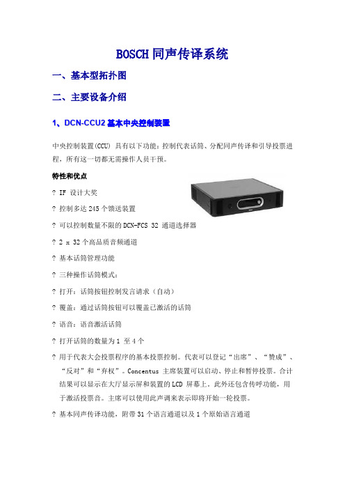
BOSCH同声传译系统一、基本型拓扑图二、主要设备介绍1、D C N-C C U2基本中央控制装置中央控制装置(CCU) 具有以下功能:控制代表话筒、分配同声传译和引导投票进程,所有这一切都无需操作人员干预。
特性和优点? IF 设计大奖? 控制多达245个馈送装置? 可以控制数量不限的DCN-FCS 32 通道选择器? 2 x 32个高品质音频通道? 基本话筒管理功能? 三种操作话筒模式:? 打开:话筒按钮控制发言请求(自动)? 覆盖:通过话筒按钮可以覆盖已激活的话筒? 语音:语音激活话筒? 打开话筒的数量为1 至4个? 用于代表大会投票程序的基本投票控制。
代表可以登记“出席”、“赞成”、“反对”和“弃权”。
Concentus 主席装置可以启动、停止和暂停投票。
合计结果可以显示在大厅显示屏和装置的LCD 屏幕上。
此外还包含传呼功能,用于激活投票音。
主席可以使用此声调来表示即将开始一轮投票。
? 基本同声传译功能,附带31个语言通道以及1个原始语言通道? 基本内部通信功能,可以指定内部通信操作人员和内部通信主席(都可以通过译员台呼叫)? 自动摄像机控制? 2 路音频线路输入和2 路音频线路输出? 可调节音频输入的灵敏度? 可调节音频输出的灵敏度? 音频插入功能,用于连接外部音频处理设备或电话耦合器? 可通过显示屏和单个旋钮对CCU 和系统进行配置? 安装人员可为每个CCU 分配唯一的名称以便识别? 通过VU 计量表读数来监控音频输入和音频输出。
可以使用耳机来监控音频? 适用于桌面或机架安装的19英寸(2U) 壳体? 方便携带的提手? 附带19 英寸机架安装支架、可拆卸支脚和安装附件? 系统安装和用户手册光盘控件和指示灯前面? 电源开关? 2 x 16 字符的 LCD 显示屏,用于显示状态和配置? 旋钮,用于浏览菜单背面? 三个红色 LED 过载指示灯,用于指示 DCN 网络输出? 绿色和黄色 LED 指示灯,用于指示以太网活动互连前面? 一个 3.5 毫米(0.14 英寸)立体声耳机插孔背面? 内置保险丝的欧式电源插座? 三个 DCN 电源插座,包括用于连接装置的锁定设施? 两个立体声莲花插非均衡音频线路输入? 一个 3 针 XLR 平衡式音频线路输出? 两个立体声莲花插非均衡音频线路输出? 一个以太网连接,用于控制PC 或开放式接口? 一个RS?232 串行数据连接器,用于控制摄像机技术指标电压 100?240 Vac 50?60 Hz功耗 295 WDCN 系统电源 40 Vdc,每个 DCN 插孔最高 85 W总功率 255 WRS-232 连接九针迷你D 凹型插孔频响 30 Hz –20 kHz(-3dB ,额定电平)额定电平时THD < 0.5 %串扰衰减 > 85 dB,1 kHz动态范围 > 90 dB信噪比 > 87 dBA音频输入莲花插额定输入 24 dBV (+/-6dB)莲花插最大输入 +0 dBV音频输出XLR 额定输出 12 dBV (+6/-24 dB)XLR 最大输出 +12 dBV莲花插额定输出 24 dBV (+6/-24 dB)莲花插最大输出 +0 dBV机械安装独立使用或安装在19 英寸支架中尺寸(高x 宽x 厚)88 x 483 x 350 毫米(含支架,不含支脚)92 x 440 x 350 毫米(不含支架,含支脚)重量 7 千克(15.4 磅)颜色碳灰色(PH 10736) 和银白色2、具有固定话筒的D C N-D I S S/D C N-D I S L讨论装置具有固定话筒的讨论装置可以使与会人员发言、登记发言请求以及听取他人发言。
博世rational combimaster
CombiMaster ® Plus / CombiMaster ®操作说明书原件2 / 107与品牌相符的全方位服务包。
我们希望您能从一开始就从您的投资中获取最大的收益。
持续整个产品生命周期,不增加额外的成本。
免费!- 现场指导我们在您自己的厨房向您的厨师展示我们的设备的工作原理,以及如何以最佳方式使用设备,满足您的全部特殊需求。
免费!- RATIONAL莱欣诺 ®遥控功能如果您的 SelfCookingCenter 膳酷盛 ®已与一个网络相连,则可使用iPhone 轻松控制并监控它。
由此可了解一切,始终知道设备中正在执行的步骤。
只需简单登录免费!- Chef✆Line®只要您对设备的使用或者菜谱有任何问题,我们都乐于在电话中为您提供咨询。
快速、简捷,厨师对讲,365 天全年无休。
Chef✆Line 联系方式电话 +49 (0) 81 91/327 561。
3 / 107RATIONAL SERVICE-PARTNER我们的设备可靠且耐用。
然而,即便出现了技术难题,RATIONAL SERVICE-PARTNER 也会快速提供帮助。
包括得到保证的备件供应和周末紧急服务: 电话 +49 (0) 81 91/327 666.2 年保修我们提供 24 个月保修,从设备初次安装之日开始计算。
前提是:您在我们这里正确且完整地登记了您的设备。
可以在 /warranty 下简单地在线登记或通过随附的邮寄卡登记。
玻璃、灯泡和密封材料的损坏以及由不当安装、使用、养护、维修和除钙而导致的损坏不在保修范围之内。
只需简单登录/warrantyCombiMaster – 超强动力设备尊敬的用户:购买CombiMaster ® Plus是您的明智之选!全新的CombiMaster ® Plus 代表着成熟的技术、卓越的食品加工质量并展现令人惊叹的、能随时实现绝佳食品品质的强大功能: 松脆的脆皮烤,多汁的烤肉,浓郁的香味和色泽。
博世同传系统手册
息容量,压缩比关系到所需的音频质量。 3. 协议生成:4 个数字信号一组,结合成信
息流,加上纠错算法。这个信息用于在 接收机处进行检错和纠错。 4. 调制:高频的载波被数字信息流进行相 位调制。 5. 辐射:最多可将 8 个调制的载波信号结 合一起送到红外辐射器,在此处载波信号被 转变成调制的红外光。 在红外辐射器中,按上述相反的过程,把调 制红外光还原成分立的模拟音频通道。
1.4 红外线传输的特点 红外线辐射是音频传输的理想载体,人 眼看不到红外线,它可以载送多个通道, 每通道分配一种语言,传送到较远的距 离。他是一种无线传输的系统,所以会 议代表不需要与系统有物理连接就可以 收听翻译语言。 1.5 会场的保密性 会议经常要讨论一些敏感话题,所以音 频信号传输的保密性就十分重要,由于 红外辐射不能穿透不透明的建筑,所以 会场本身就起到阻挡红外辐射外泄和防 止窃听的效果。 1.6 在相邻房间中的语言分配 红外系统特别适合有多厅的会议中心, 由于墙体阻挡红外线的穿透,相邻会议 室不会互相干扰。 1.7 不受灯光的干扰 传统红外语言分配系统容易到照明灯 光的干扰。新型(荧光)灯具的工作频 率较高,使这个问题更加严重,Integrus 采用更高的频段,彻底解决了这个难 题。它工作在 2-8MHZ 的波段,避免了 来自各种照明灯光的干扰,由此带来了 2 个优点,其一是音质大大提高。其二 是系统更适合用在出租业务,因为出租 的系统必须适应各种照明环境。 1.8 音频质量 Integrus 系统具有大大提高的音频质量, 更好的压缩技术和更高的信噪比,使接 收到的信号更为清晰,同时消除了上文 所述的灯光干扰。清晰的语言使代表长 期收听不感觉疲劳,所以代表可以集中 精力长时间地参加到会议中去。 1.9 通道的数量 Integrus 系统在选择需用通道方面给使 用人极大的灵活性,使用较高的频段 (2-8MHZ),可以用 4 种不同的质量模
2018-博世,move,说明书-word范文模板 (10页)
本文部分内容来自网络整理,本司不为其真实性负责,如有异议或侵权请及时联系,本司将立即删除!== 本文为word格式,下载后可方便编辑和修改! ==博世,move,说明书篇一:博世欧洲精英使用手册博世欧洲精英使用手册一、设备打开1.按下锅炉控制面板左上角的电源开关,运行设备;2.控制面板下方的运行指示灯亮,温度指示灯显示采暖或生活热水温度。
燃烧过程中,燃烧器指示灯亮。
二、打开集中供热功能1.旋转采暖温度控制按钮(控制面板左边一个按钮),调节采暖温度:——地板采暖:位置2(约50℃)。
注:初次使用温度不宜调的太高,一般在20至30℃即可。
最高温度不得超过60℃。
——散热片系统:位置6(约80℃).利用热水温度调节按钮,,调节生活热水温度。
温度指示不显示热水温度,加热过程中,温度显示灭,当燃烧器点燃后,燃烧器指示灯亮起。
热水温度可设置在40℃-60℃之间,单实际温度取决于热水量,热水量越大,温度越低。
四、夏季模式(集中供热关闭,仅热水打开) 1.保持设备打开状态。
2.逆时针旋转采暖温度控制按钮,至最左端。
采暖泵关闭。
3.夏季模式下,温度指示关闭。
注:当压力表水压低于正常水压时,应打开补水阀补水,直到水压压力处于正常范围内。
然后一定要关闭补水阀,否则会造成锅炉泄水。
五、故障代码博世欧洲之星操作手册一、设备打开1.首先确认燃气阀门已经打开,锅炉电源插头已插上; 2.按下锅炉控制面板左上角的电源开关,运行设备; 3.显示屏上显示采暖的出水温度二、试运行:1.打开系统散热片的所有阀门;2.打开补水阀,生活冷水阀,注水至1到2巴的压力,然后关闭冷水阀 3.散热片排气;4.打开冷水阀,将系统压力重新充注到1-2巴 5.打开燃气阀三、打开集中供热功能1.热水温度可设置在45℃至82℃之间;2.若为地板采暖系统,采暖温度不得高于60℃;3.旋转控制面板左下角的采暖控制旋钮,调节采暖温度;(初次使用时不宜调太高) 4.采暖类型不同,最大采暖出水温度设置不同:——地板采暖系统:2档(约50℃)四、生活热水温度设置1.调节锅炉控制面板右下角的生活热水温度调节旋钮来设置生活热水温度;2.显示屏上显示的仍是采暖出水温度 3.生活热水温度可在40℃和60℃之间设置。
boschng会议系统方案(同传、跟踪)
BOSCH会议系统项目方案书第一章设计思想随着时代的发展,信息交流变的越来越重要,对信息交流的方式、方法的要求也越来越高,尤其是当今现代化的多媒体会议厅堂的视听设备组成,已越来越完善和先进。
现代化的多媒体会议厅堂涵盖了多功能会议室、学术交流会议厅、多功能国际会议厅、现代化培训室、指挥室等对功能要求较高、较完善的厅堂功能,所以数字会议系统、音频扩声系统、视频会议系统、视频演示系统、中央控制系统在此类环境中的应用越来越广泛和重要。
用户要求可以通过中央控制系统,高度自动化地对现代化多媒体会议厅堂中立体分布的各种复杂的视听设备进行集中控制,使这个系统更加完善、完整、完美。
会议报告厅内的音视频设备很多,系统也非常复杂,综合了数字会议、音频扩声、多媒体演示、监控摄像、中央控制等众多不同类型的产品,涉及声光、电、信息学等多个领域。
因此,各种产品相互间的协调操作非常重要。
系统集成的好坏,关系到整个系统的成败。
根据贵单位的实际需要,提出如下总体设计要求:1.系统的先进性与稳定性多功能报告厅是重要的会议培训场所,在这里举行的会议的重要性不言而喻。
因此,该系统采用的技术必须是先进的,选用的设备必须是十分可靠的,且系统整体集成必须具有高稳定性。
2.系统的集成性模块是集散的,系统是集成的。
由于会议种类不同、规模不同,对会议系统的要求也不同,故会议系统中各子系统具有模块化结构,既能独立工作,也能集中并行控制。
可以说,系统的优越性很大程度取决于系统的集成程度。
3.系统操作的便捷和灵活性系统设计功能的要完善,但使用维护要方便,同时又要考虑到系统良好的性价比。
4.系统的可扩展性我们设计的系统具有很强的扩充性,满足现代化科技发展的需求。
足够的扩展余地为用户将来的升级提供条件。
5.系统的经济性追求高效、低成本是每个甲方所希望的。
我们所推荐的系统具有除了本身的性价比高以外,具有免维护特点。
有效地降低了系统建设成本和系统维护成本。
第二章设计依据系统标准参照:国际标准化组织标准ISO国际电气电子工程师协会标准 IEEE国际电工委员会标准 IEC供电电源标准 GB2887-82计算机场地技术要求 GBJ45—82国际商务建筑线缆标准 TIA/EIA 568国际商务建筑通信基础管理标准 TIA/EIA 606国际商务建筑通信设施规划和管路敷设标准 TIA/EIA 569扩声系统技术标准参照:中华人民共和国文化部行业技术标准《WH0301-93》一级标准。
- 1、下载文档前请自行甄别文档内容的完整性,平台不提供额外的编辑、内容补充、找答案等附加服务。
- 2、"仅部分预览"的文档,不可在线预览部分如存在完整性等问题,可反馈申请退款(可完整预览的文档不适用该条件!)。
- 3、如文档侵犯您的权益,请联系客服反馈,我们会尽快为您处理(人工客服工作时间:9:00-18:30)。
Installation mode,press ‘Floor’to enteror ‘Mute’ toclear, use‘Relay select’ knobtoselectoption andB-select ‘<>’keys to selectnext orpreviousFunction.
●已打开的话筒红色“光环”指示器亮,话筒键LED指示器为红色。
●后按键的代表机处于等待申请状态,话筒键LED指示器为绿色。
●当关闭一个打开的话筒时,首先处于申请状态的代表机自动打开。
以申请的时间先后顺序为准。
*建议:使用该状态,可靠且方便。
在“OVERRIDE”状态下(越权状态)
●最多可同时打开的代表机数量为设定的话筒同时启用数量。
选择语言列表:<英语>法语
用‘Relay select’旋钮将<>定在ENGLISH上。
按‘Floor’键确认。此时<>变为[]以示确认。
第七步:按B-select的‘’键选择下一个菜单,显示
Selectlanguageforchannel 1:<CHINESE>
选择1翻译语言通道使用的语言:<汉语>
通道语言用户最初已经选定,例:汉语---CHI、英语---ENG、德语---GER、法语---FR、日语---JAP
用‘Relayselect’旋钮将<>定在CHI上。第二台为ENG,依次类推。
按‘Floor’键确认。此时<>变为[ ]以示确认。
第八步:按B-select的‘’键选择下一个菜单,显示
<1>2345 6 7 891011 12 1314
选择房间号:<1> 2 3 4 5 6 7891011 1213 14
用‘Relayselect’旋钮将<>定在1上。
按‘Floor’键确认。此时<>变为[]以示确认。
第四步:按B-select的‘’键选择下一个菜单,显示
Select desknumber:<1> 23 4 56
——“4”:同时启动用4个话筒。
打开第一个话筒讲话。此时该代表机扬声器关闭。
调节中央控制器音量控制旋钮。
调节中央控制器高、低音音调旋钮。
持续按下主席机优先控制键(蓝色键),可暂时关闭所有话筒,此时只有主席机可以发言。
松开此键,恢复原先的话筒状态。
在“OPEN”状态下(申请状态)
●最多可同时打开的代表机数量为设定的话筒同时启用数量。
博世同传操作说明书
————————————————————————————————作者:
———————————————————————————————— 日期:
ﻩ
博世操作说明
1、数字会议系统操作说明
系统简介
会议发言系统采用DCN系统模块化的设计,根据不同的需求配备相应的功能模*建议:不要使用该状态,以免产生不必要的麻烦。
2、同声传译设备操作说明
(1)红外发射机
打开设备电源(注意:此电源在设备的后面)。
把所有的通道全部打开(此时的四个小液晶显示屏上自上而下分别显示——0,1,2,3)。
拨位开关状态设置成“NORMAL”(如下图)。
(2)红外发射板
确保该设备通电。通电时,发射板左上角的指示灯亮。
选择桌面号:<1>23 4 5 6
每个房间只有一台译员机,因此所有译员机此项均选为1。
用‘Relay select’旋钮将< >定在1上。
按‘Floor’键确认。此时<>变为[]以示确认。
第五步:按B-select的‘’键选择下一个菜单,显示
Select numberof channels:<1> 23 45678910 11
选择使用者语言:<英语>法语德语意大利语西班牙语
用‘Relay select’旋钮将<>定在ENGLISH上。
按‘Floor’键确认。此时<>变为[]以示确认。如确认有误,按‘Mute’键消除,[]变为< >,再重新选择确认。
第三步:按B-select的‘’键选择下一个菜单,显示
“Select booth number:
Selectoutgoing channel via A - output:
<1> 2 3 45 6 7 8 9 10 11 121314
安装方法:按‘Floor’键确认,按‘Mute’键消除,用‘Relayselect’旋钮选项,用B-select的‘’键和‘’键选择下一个或前一个菜单。
第二步:按B-select的‘’键选择下一个菜单,显示
Select userlanguage:
<ENGLISH>FRANCAISDEUTCH ITALIAND ESPANOL NEDERLANDS
选择翻译语言通道数目:<1>2 3 456 7 8 91011
用户有1台译员机,译员机此项均选为1。
用‘Relayselect’旋钮将<>定在1上。
按‘Floor’键确认。此时< >变为[ ]以示确认。
第六步:按B-select的‘’键选择下一个菜单,显示
Selectlanguagelist:
<ENGLISH> FRENCHNORIGNAL
●已打开的话筒红色“光环”指示器亮,话筒键LED指示器为红色。
●后按键的代表机将直接打开,同时关闭第一个打开的话筒,以话筒打开的时间先后顺序为准。
在“VOICE”状态下(声控状态)
●最多可同时打开的代表机数量为设定的话筒同时启用数量。
●所有话筒处于等待状态,各类指示器不起作用。
●当有发言时,自动打开当前话筒。当发言结束,话筒自动恢复成等待状态。
中央控制器(CCU)
系统上电
在中央控制器上设定话筒工作状态为“OPEN”
——“OPEN”:话筒键控制,申请发言。
——“OVERRIED”:话筒键控制,越权发言。
——“VOICE”:声控启动话筒。
在中央控制器上设定话筒同时启动用数量为“1”
——“1”:同时启动用1个话筒。
——“2”:同时启动用2个话筒。
设备安装在会场里(如下图)。
(3)红外接收机
首先插上耳机,调整到需要的通道,若无信号,则按一下接收机的开关“ON”(如下图)。
(4)译员台
设置 :
用户先行安排译员机所需翻译出的语种。
例:第一台译员机------将其它语言翻译成汉语
确认设备连接完毕,打开中央控制器电源,等待数秒,译员机液晶屏显示
然后开始进行安装。