JEM_20101547
SAE J17112010

entirely voluntary, and its applicability and suitability for any particular use, including any patent infringement arising therefrom, is the sole responsibility of the user.”
SAE reviews each technical report at least every five years at which time it may be reaffes your written comments and suggestions.
SURFACE VEHICLE RECOMMENDED PRACTICE
J1711 JUN2010
Issued Revised
1999-03 2010-06
Superseding J1711 MAR1999
(R) Recommended Practice for Measuring the Exhaust Emissions and Fuel Economy of Hybrid-Electric Vehicles, Including Plug-in Hybrid Vehicles
Copyright © 2010 SAE International
All rights reserved. No part of this publication may be reproduced, stored in a retrieval system or transmitted, in any form or by any means, electronic, mechanical,
J-STD-075_post_april_ballot
3
4 Agreements
3
5 Applicable Documents
3
6 Solderability
3
7 Process
3
7.1 Process Sensitive Components
4
7.2 PSL Reclassification
4
7.3 PSL Evaluation
4
7.4 MSL Bake Out Conditions
6 Solderability: Component solderability shall be evaluated and classified according to J-STD-002.
7 Process: The process for using this specification is outlined in Figure 7-1.
10
15 MSL Classification and Labeling/Packing
11
16 PSL Labeling
11
Standard Improvement Form
end
2
UPDATED DRAFT DOCUMENT POST APRIL 2008 BALLOTING WITH EDITORIAL CORRECTIONS (READY FOR PUBLICATION) 4-11-08
3 Definitions
Family
A grouping of components by similar/common characteristics (e.g. package; design; materials; technology and or manufacturing process).
空冷凝汽器(ACC)的气密性试验

PlantDatong 1Subject空冷凝汽器真空系统气密试验规程Document-Id.Page 1 of 10 26.08.93 / NPRev. 2, 06.08.99 / NPRev. 3, 04.06.02 /HDSGEAEnergietechnik GmbH 空冷凝汽器(ACC)的气密性试验内容页数 1 气密试验 2 1.1 主题 2 1.2 气压法气密性试验 3 1.2.1系统边界 3 1.2.2材料 3 1.2.3试验程序 4 1.2.4安全注意事项 5 1.3 真空气密性试验 6 1.3.1系统边界 6 1.3.2材料 6 1.3.3试验程序 6 1.4 真空衰减试验 7 1.4.1系统边界 7 1.4.2材料 7 1.4.3试验程序 8 1.5 故障排除 9 1.6 泄漏检测程序 10PlantDatong 1Subject空冷凝汽器真空系统气密试验规程Document-Id.Page 2 of 10 26.08.93 / NPRev. 2, 06.08.99 / NPRev. 3, 04.06.02 /HDSGEAEnergietechnik GmbH 空冷凝汽器(ACC) 1 气密试验 1.1 主题对于汽轮机发电厂的真空系统,尽最大可能防止任何超过额定量的空气泄漏是至关重要的。
真空系统由下列部分构成:? 汽轮机及其辅机的真空系统? 空冷凝汽器及其辅机的真空系统为了确保空冷凝汽器的真空系统的气密性,必须进行下列工作:? 电厂停机时的气密试验? 电厂运行时的气密试验电厂停机时的气密试验安装完成后的任何必要的时候都可以进行撈狗狗狗狗ㄆㄆㄆㄆ苄允匝閿苄允匝閿苄允匝閿苄允匝閿。
有时,如果预先安排好并可能实施,就可以安排随后进行撜婵掌婵掌婵掌婵掌苄允匝閿苄允匝閿苄允匝閿苄允匝閿以确保系统在真空状态下的气密性。
电厂运行时的气密试验电厂在运行试验期间,仅可以进行撜婵账婵账婵账婵账ゼゼゼゼ跏匝閿跏匝閿跏匝閿跏匝閿以检查气密性。
sp232
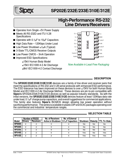
■Operates from Single +5V Power Supply ■Meets All RS-232D and ITU V.28Specifications■Operates with 0.1µF to 10µF Capacitors ■High Data Rate – 120Kbps Under Load ■Low Power Shutdown ≤1µA (Typical)■3-State TTL/CMOS Receiver Outputs ■Low Power CMOS – 3mA Operation ■Improved ESD Specifications:±15kV Human Body Model±15kV IEC1000-4-2 Air Discharge ±8kV IEC1000-4-2 Contact DischargeNumber of RS232No. of Receivers No. of ExternalModel Drivers Receivers Active in Shutdown 0.1µF CapacitorsShutdown WakeUp TTL Tri–StateSP202E 220 4No No No SP232E 220 4No No No SP233E 220 0No No No SP310E 220 4Yes No Yes SP312E222 4Yes Yes YesDESCRIPTIONSELECTION TABLEThe SP202E/232E/233E/310E/312E devices are a family of line driver and receiver pairs that meet the specifications of RS-232 and V.28 serial protocols with enhanced ESD performance.The ESD tolerance has been improved on these devices to over ±15KV for both Human Body Model and IEC1000-4-2 Air Discharge Method. These devices are pin-to-pin compatible withSipex's SP232A/233A/310A/312A devices as well as popular industry standards. As with the initial versions, the SP202E/232E/233E/310E/312E devices feature at least 120Kbps data rate under load, 0.1µF charge pump capacitors, and overall ruggedness for commercial applications.This family also features Sipex's BiCMOS design allowing low power operation without sacrificing performance. The series is available in plastic DIP and SOIC packages operating over the commercial and industrial temperature ranges.CC 1OUT 1IN 1OUT 1IN 2IN 2OUTC 1+V+C 1-C 2+C 2-V-T 2OUT R 2INNow Available in Lead Free PackagingThis is a stress rating only and functional operation of the device at these or any other conditions above those indicated in the operation sections of this specification is not implied. Exposure to absolute maximum rating conditions for extended periods of time may affect reliability.V cc .................................................................................................................................................................+6V V +....................................................................................................................(Vcc-0.3V) to +11.0V V -............................................................................................................................................................-11.0V Input VoltagesT IN .........................................................................................................................-0.3 to (Vcc +0.3V)R IN ............................................................................................................................................................±15V Output VoltagesT OUT ....................................................................................................(V+, +0.3V) to (V-, -0.3V)R OUT ................................................................................................................-0.3V to (Vcc +0.3V)Short Circuit DurationT OUT .........................................................................................................................................ContinuousV CC =+5V ±10%; 0.1µF charge pump capacitors; T MIN to T MAX unless otherwise noted.ELECTRICAL CHARACTERISTICSPlastic DIP ..........................................................................375mW (derate 7mW/°C above +70°C)Small Outline ......................................................................375mW (derate 7mW/°C above +70°C)ABSOLUTE MAXIMUM RATINGSPERFORMANCE CURVES-55-400257085125Temperature (°C)051015202530V CC = 6VV CC = 5VV CC = 4VV CC = 3VI C C (m A )05101520Load Current (mA)681012V + (V o l t s )24V CC = 5V V CC = 4VV CC = 6V253035402468101214Load Current (mA)V – V o l t a g e (V o l t s )-3-4-5-6-7-8-9-10-11V CC = 6VV CC = 5VV CC = 4V2OUT 2IN 2OUT 2-2+1–1+2+2–T 2IN T 1IN R 1OUT R 1IN T 1OUT GND V CC V+GNDV–CC 1OUT 1IN 1OUT 1IN 2IN 2OUTC 1+V+C 1-C 2+C 2-V-T 2OUT R 2INT CC 1OUT 1IN 1OUT 1IN 2IN 2OUTNC *C 1+V+C 1-C 2+C 2-V-T 2OUT R 2INCC 1OUT 1IN 1OUT 1IN 2IN 2OUTC 1+V+C 1-C 2+C 2-V-T 2OUT R 2IN* N.C. for SP310E_A, EN for SP312E_APINOUTS4.54.755.0 5.25 5.5V CC (Volts)5.06.57.07.58.08.59.0Load current = 0mA T A = 25°CV O H (V o l t s )5.56.0FEATURES…The SP202E/232E/233E/310E/312E devices are a family of line driver and receiver pairs that meet the specifications of RS-232 and V.28 serial protocols with enhanced ESD perfor-mance. The ESD tolerance has been improved on these devices to over ±15KV for both Human Body Model and IEC1000-4-2 Air Discharge Method. These devices are pin-to-pin compat-ible with Sipex's232A/233A/310A/312A devices as well as popular industry standards. As with the initial versions, the SP202E/232E/ 233E/310E/312E devices feature10V/µs slew rate, 120Kbps data rate under load, 0.1µF charge pump capacitors, overall ruggedness for commercial applications, and increased drive current for longer and more flexible cable configurations. This family also features Sipex's BiCMOS design allowing low power operation without sacrificing performance.The SP202E/232E/233E/310E/312E devices have internal charge pump voltage converters which allow them to operate from a single +5V supply. The charge pumps will operate with polarized or non-polarized capacitors ranging from 0.1 to 10 µF and will generate the ±6V needed to generate the RS-232 output levels. Both meet all EIA RS-232 and ITU V.28 specifications.The SP310E provides identical features as the SP232E with a single control line which simultaneously shuts down the internal DC/DC converter and puts all transmitter and receiver outputs into a high impedance state. The SP312E is identical to the SP310E with separate tri-state and shutdown control lines.THEORY OF OPERATIONThe SP232E,SP233E,SP310E and SP312E devices are made up of three basic circuit blocks –1) a driver/transmitter, 2) a receiver and 3) a charge pump. Each block is described below.Driver/TransmitterThe drivers are inverting transmitters, which ac-cept TTL or CMOS inputs and output the RS-232 signals with an inverted sense relative to the input logic levels. Typically the RS-232output voltage swing is ±6V. Even under worst case loading conditions of 3kOhms and 2500pF, the output is guaranteed to be ±5V, which is consistent with the RS-232 standard specifications. The transmitter outputs are protected against infinite short-circuits to ground without degradation in reliability.Figure 1. Typical Circuit using the SP202E or SP232E.The instantaneous slew rate of the transmitteroutput is internally limited to a maximum of 30V/µs in order to meet the standards [EIA RS-232-D 2.1.7, Paragraph (5)]. However, the transition re-gion slew rate of these enhanced products is typi-cally 10V/µs. The smooth transition of the loaded output from V OL to V OH clearly meets the mono-tonicity requirements of the standard [EIA RS-232-D 2.1.7, Paragraphs (1) & (2)].ReceiversThe receivers convert RS-232 input signals to inverted TTL signals. Since the input is usually from a transmission line, where long cable lengthsand system interference can degrade the signal, the inputs have a typical hysteresis margin of 500mV.This ensures that the receiver is virtually immune to noisy transmission lines.The input thresholds are 0.8V minimum and 2.4V maximum, again well within the ±3V RS-232requirements. The receiver inputs are also pro-tected against voltages up to ±15V. Should an input be left unconnected, a 5KOhm pulldown resistor to ground will commit the output of the receiver to a high state.Figure 2. Typical Circuits using the SP233ECP and SP233ECTFigure 3. Typical Circuits using the SP310E and SP312EFigure 4. Charge Pump — Phase 1Figure 5. Charge Pump — Phase 2In actual system applications, it is quite possible for signals to be applied to the receiver inputs before power is applied to the receiver circuitry.This occurs, for example, when a PC user attempts to print, only to realize the printer wasn’t turned on.In this case an RS-232 signal from the PC will appear on the receiver input at the printer. When the printer power is turned on, the receiver will operate normally. All of these enhanced devices are fully protected.Charge PumpThe charge pump is a Sipex –patented design (5,306,954) and uses a unique approach com-pared to older less–efficient designs. The charge pump still requires four external capacitors, but uses a four–phase voltage shifting technique to attain symmetrical power supplies. There is a free–running oscillator that controls the four phases of the voltage shifting. A description of each phase follows.Phase 1— V SS charge storage —During this phase of the clock cycle, the positive side of capacitors C 1 and C 2 are initially charged to +5V. C l + is then switched to ground and the charge in C 1– is transferred to C 2–. Since C 2+ is connected to +5V, the voltage potential across capacitor C 2 is now 10V.Phase 2— V SS transfer — Phase two of the clock con-nects the negative terminal of C 2 to the V SS storage capacitor and the positive terminal of C 2to ground, and transfers the generated –l0V to C 3. Simultaneously, the positive side of capaci-tor C 1 is switched to +5V and the negative side is connected to ground.Phase 3— V DD charge storage — The third phase of the clock is identical to the first phase — the charge transferred in C 1 produces –5V in the negative terminal of C 1, which is applied to the negative side of capacitor C 2. Since C 2+ is at +5V, the voltage potential across C 2 is l0V.Phase 4— V DD transfer — The fourth phase of the clock connects the negative terminal of C 2 to ground,and transfers the generated l0V across C 2 to C 4,the V DD storage capacitor. Again, simultaneously with this, the positive side of capacitor C 1 is switched to +5V and the negative side is con-nected to ground, and the cycle begins again.Since both V + and V – are separately generated from V CC ; in a no–load condition V + and V – willFigure 6. Charge Pump Waveforms+10Va) C 2+GND GNDb) C 2––10VFigure 7. Charge Pump — Phase 3Figure 8. Charge Pump — Phase 4be symmetrical. Older charge pump approaches that generate V – from V + will show a decrease in the magnitude of V – compared to V + due to the inherent inefficiencies in the design.The clock rate for the charge pump typically operates at 15kHz. The external capacitors can be as low as 0.1µF with a 16V breakdown voltage rating.Shutdown (SD) and Enable (EN) for the SP310E and SP312EBoth the SP310E and SP312E have a shutdown/standby mode to conserve power in battery-pow-ered systems. To activate the shutdown mode,which stops the operation of the charge pump, a logic “0” is applied to the appropriate control line.For the SP310E , this control line is ON/OFF (pin 18). Activating the shutdown mode also puts theSP310E transmitter and receiver outputs in a high impedance condition (tri-stated). The shutdown mode is controlled on the SP312E by a logic “0”on the SHUTDOWN control line (pin 18); this also puts the transmitter outputs in a tri–state mode. The receiver outputs can be tri–stated separately during normal operation or shutdown by a logic “1” on the ENABLE line (pin 1).Wake–Up Feature for the SP312EThe SP312E has a wake–up feature that keeps all the receivers in an enabled state when the device is in the shutdown mode. Table 1 defines the truth table for the wake–up function.With only the receivers activated, the SP312E typically draws less than 5µA supply current. In the case of a modem interfaced to a computer in power down mode, the Ring Indicator (RI) signal from the modem would be used to "wake up" the computer, allowing it to accept data transmission.After the ring indicator signal has propagated through the SP312E receiver, it can be used to trigger the power management circuitry of the computer to power up the microprocessor, and bring the SD pin of the SP312E to a logic high, taking it out of the shutdown mode. The receiver propagation delay is typically 1µs. The enable time for V+ and V– is typically 2ms. After V+ and V– have settled to their final values, a signal can be sent back to the modem on the data terminal ready (DTR) pin signifying that the computer is ready to accept and transmit data.Pin Strapping for the SP233ECTThe SP233E packaged in the 20–pin SOIC pack-age (SP233ECT) has a slightly different pinout than the SP233E in other package configurations. To operate properly, the following pairs of pins must be externally wired together:the two V– pins (pins 10 and 17)the two C2+ pins (pins 12 and 15)the two C2– pins (pins 11 and 16)All other connections, features, functions and performance are identical to the SP233E as specified elsewhere in this data sheet.ESD TOLERANCEThe SP202E/232E/233E/310E/312E devices incorporates ruggedized ESD cells on all driver output and receiver input pins. The ESD struc-ture is improved over our previous family for more rugged applications and environments sen-sitive to electro-static discharges and associated transients. The improved ESD tolerance is at least ±15KV without damage nor latch-up. There are different methods of ESD testing applied:a) MIL-STD-883, Method 3015.7b) IEC1000-4-2 Air-Dischargec) IEC1000-4-2 Direct ContactThe Human Body Model has been the generally accepted ESD testing method for semiconductors. This method is also specified in MIL-STD-883, Method 3015.7 for ESD testing. The premise of this ESD test is to simulate the human body’s potential to store electro-static energy and discharge it to an integrated circuit. The simulation is performed by using a test model as shown in Figure 9. This method will test the IC’s capability to withstand an ESD transient during normal handling such as in manufacturing areas where the ICs tend to be handled frequently.The IEC-1000-4-2, formerly IEC801-2, is generally used for testing ESD on equipment and systems. For system manufacturers, they must guarantee a certain amount of ESD protection since the system itself is exposed to the outside environment and human presence. The premiseTable 1. Wake-up Function Truth Table.Figure 9. ESD Test Circuit for Human Body ModelFigure 10. ESD Test Circuit for IEC1000-4-2with IEC1000-4-2 is that the system is required to withstand an amount of static electricity when ESD is applied to points and surfaces of the equipment that are accessible to personnel during normal usage. The transceiver IC receives most of the ESD current when the ESD source is applied to the connector pins. The test circuit for IEC1000-4-2 is shown on Figure 10. There are two methods within IEC1000-4-2, the Air Discharge method and the Contact Discharge method.With the Air Discharge Method, an ESD voltage is applied to the equipment under test (EUT)through air. This simulates an electrically charged person ready to connect a cable onto the rear of the system only to find an unpleasant zap just before the person touches the back panel. The high energy potential on the person discharges through an arcing path to the rear panel of the system before he or she even touches the system.This energy, whether discharged directly or through air, is predominantly a function of theSP202E HUMAN BODY IEC1000-4-2FamilyMODEL Air Discharge Direct Contact LevelDriver Outputs ±15kV ±15kV ±8kV 4Receiver Inputs ±15kV±15kV±8kV4Figure 11. ESD Test Waveform for IEC1000-4-2t=0nst=30ns0A15A30At ➙i ➙Table 2. Transceiver ESD Tolerance Levelsdischarge current rather than the discharge voltage. Variables with an air discharge such as approach speed of the object carrying the ESD potential to the system and humidity will tend to change the discharge current. For example, the rise time of the discharge current varies with the approach speed.The Contact Discharge Method applies the ESD current directly to the EUT. This method was devised to reduce the unpredictability of the ESD arc. The discharge current rise time is constant since the energy is directly transferred without the air-gap arc. In situations such as hand held systems, the ESD charge can be directlydischarged to the equipment from a person already holding the equipment. The current is transferred on to the keypad or the serial port of the equipment directly and then travels through the PCB and finally to the IC.The circuit models in Figures 9 and 10 represent the typical ESD testing circuit used for all three methods. The C S is initially charged with the DC power supply when the first switch (SW1) is on.Now that the capacitor is charged, the second switch (SW2) is on while SW1 switches off. The voltage stored in the capacitor is then applied through R S , the current limiting resistor, onto the device under test (DUT). In ESD tests, the SW2switch is pulsed so that the device under test receives a duration of voltage.For the Human Body Model, the current limiting resistor (R S ) and the source capacitor (C S ) are 1.5k Ω an 100pF, respectively. For IEC-1000-4-2, the current limiting resistor (R S ) and the source capacitor (C S ) are 330Ω an 150pF, respectively.The higher C S value and lower R S value in the IEC1000-4-2 model are more stringent than the Human Body Model. The larger storage capacitor injects a higher voltage to the test point when SW2 is switched on. The lower current limiting resistor increases the current charge onto the test point.D 2x 2E1A1DETAIL A- - 2.00.05 - -Dimensions in (mm)20 PIN SSOP JEDEC MO-150(AE) V ariation1.65 1.75 1.850.22 - 0.380.09 - 0.250.55 0.75 0.950º 4º 8ºA A1A2b c D E E1L L1ØMIN NOM MAX 7.407.808.205.005.305.601.25 REF6.907.207.5020 PIN SSOPPACKAGE: 20 PIN SSOPPACKAGE: 16 PIN NSOIC16 PIN NSOICPACKAGE: 16 PIN WSOIC16 PIN SOIC WIDE- - .210.015 -Dimensions in inches 18 PIN PDIP JEDEC MS-001(AC) V ariation.115 .130 .195 .014 .018 .022.045 .060 .070.240 .250 .280A A1A2b c D1E E1e eA eB .115 .130 .150LMIN NOM MAX b2b3.030 .039 .045D .008.010.014.880.900.920.005.300.310.325.100 BSC .300 BSC .430-----18 pin PDIPPACKAGE: 18 PIN PDIPPart Number Temperature Range Topmark Package SP202ECN.............................0°C to +70°C.................................SP202ECN........................................................................16–pin NSOIC SP202ECN/TR.......................0°C to +70°C.................................SP202ECN........................................................................16–pin NSOIC SP202ECP.............................0°C to +70°C.................................SP202ECP.........................................................................16–pin PDIP SP202ECT.............................0°C to +70°C.................................SP202ECT.........................................................................16–pin WSOIC SP202ECT/TR.......................0°C to +70°C.................................SP202ECT.........................................................................16–pin WSOIC SP202EEN..........................–40°C to +85°C................................SP202EEN.........................................................................16–pin NSOIC SP202EEN/TR....................–40°C to +85°C................................SP202EEN.........................................................................16–pin NSOIC SP202EEP..........................–40°C to +85°C................................SP202EEP.........................................................................16–pin PDIP SP202EET..........................–40°C to +85°C................................SP202EET..........................................................................16–pin WSOIC SP202EET/TR.....................–40°C to +85°C................................SP202EET..........................................................................16–pin WSOIC SP232ECN.............................0°C to +70°C................................SP232ECN..........................................................................16–pin NSOIC SP232ECN/TR.......................0°C to +70°C................................SP232ECN..........................................................................16–pin NSOIC SP232ECP.............................0°C to +70°C.................................SP232ECP.........................................................................16–pin PDIP SP232ECT.............................0°C to +70°C.................................SP232ECT..........................................................................16–pin WSOIC SP232ECT/TR.......................0°C to +70°C.................................SP232ECT..........................................................................16–pin WSOIC SP232EEN..........................–40°C to +85°C................................SP232EEN..........................................................................16–pin NSOIC SP232EEN/TR....................–40°C to +85°C................................SP232EEN..........................................................................16–pin NSOIC SP232EEP..........................–40°C to +85°C................................SP232EEP..........................................................................16–pin PDIP SP232EET..........................–40°C to +85°C................................SP232EET...........................................................................16–pin WSOIC SP232EET/TR.....................–40°C to +85°C................................SP232EET...........................................................................16–pin WSOIC SP233ECT............................0°C to +70°C.................................SP233ECT...........................................................................20–pin WSOIC SP233ECT/TR......................0°C to +70°C.................................SP233ECT...........................................................................20–pin WSOIC SP233EET..........................–40°C to +85°C................................SP233EET...........................................................................20–pin WSOIC SP233EET/TR.....................–40°C to +85°C................................SP233EET...........................................................................20–pin WSOIC SP310ECP............................0°C to +70°C.................................SP310ECP.........................................................................18–pin PDIP SP310ECT............................0°C to +70°C.................................SP310ECT..........................................................................18–pin WSOIC SP310ECT/TR......................0°C to +70°C.................................SP310ECT..........................................................................18–pin WSOIC SP310ECA............................0°C to +70°C.................................SP310ECA..........................................................................20–pin SSOP SP310ECA/TR......................0°C to +70°C.................................SP310ECA..........................................................................20–pin SSOP SP310EEP..........................–40°C to +85°C................................SP310EEP..........................................................................18–pin PDIP SP310EET..........................–40°C to +85°C................................SP310EET...........................................................................18–pin WSOIC SP310EET/TR.....................–40°C to +85°C................................SP310EET...........................................................................18–pin WSOIC SP310EEA..........................–40°C to +85°C................................SP310EEA...........................................................................20–pin SSOP SP310EEA/TR.....................–40°C to +85°C................................SP310EEA...........................................................................20–pin SSOP SP312ECP............................0°C to +70°C.................................SP312ECP..........................................................................18–pin PDIP SP312ECT............................0°C to +70°C.................................SP312ECT...........................................................................18–pin WSOIC SP312ECT/TR......................0°C to +70°C.................................SP312ECT...........................................................................18–pin WSOIC SP312ECA............................0°C to +70°C.................................SP312ECA...........................................................................20–pin SSOP SP312ECA/TR......................0°C to +70°C.................................SP312ECA...........................................................................20–pin SSOP SP312EEP..........................–40°C to +85°C................................SP312EEP...........................................................................18–pin PDIP SP312EET..........................–40°C to +85°C................................SP312EET............................................................................18–pin WSOIC SP312EET/TR.....................–40°C to +85°C................................SP312EET............................................................................18–pin WSOIC SP312EEA..........................–40°C to +85°C................................SP312EEA............................................................................20–pin SSOP SP312EEA/TR.....................–40°C to +85°C................................SP312EEA............................................................................20–pin SSOPapplication or use of any product or circuit described hereing; neither does it convey any license under its patent rights nor the rights of others.Available in lead free packaging. To order add "-L" suffix to part number.Example: SP312EEA/TR = standard; SP312EEA-L/TR = lead free /TR = Tape and ReelPack quantity is 1,500 for SSOP or WSOIC and 2,500 for NSOIC.Sipex Corporation Headquarters and Sales Office233 South Hillview Drive Milpitas, CA 95035TEL: (408) 934-7500FAX: (408) 935-7600ORDERING INFORMATIONREVISION HISTORY。
聚四氟压力表垫型号

237 238 239 240 241 242 243 244 245 246 247 248 249 250 251 252 253 254 255 256 257 258 259 260 261 262 263 264 265 266 267 268
269 270 271 272 273 274 275 276 277 278 279 280 281 282 283 284 285 286 287 288 289 290 291 292
刘涛
2012.5.8 王时睿
2012.5.8 刘涛
低温低压用 高温高压用 铠装温度计用 铠装温度计用 变送器用 双金属温度表用 双金属温度表用 双金属温度表用
办人:
办人:
生技部:
负责人:
经办人:
92 93 94 95 96 97 98 99 100 101 102 103 104 105 106 107
108 109 110 111 112 113 114 115 116 117 118 119 120 121 122 123 124 125 126 127 128 129 130 131 132 133 134 135 136 137 138 139
表
2012年 05月 01日
备注
紧急计划
月计划
紧急计划 紧急计划 月计划 锅炉定排电动门 锅炉定排电动门 #1吸收塔pH1 #11脱硫系统#1-A石膏排出泵出口PH
钢灰库提升机
时间 2012.5.8 2012.5.8
申报人
王时睿
2012.5.2
2012.5.2 2012.5.2 2012.5.2
21
聚四氟垫
22
聚四氟垫
24
瓦里安356-LC控制软件操作手册说明书
OPERATOR’S MANUALFORVarian 356-LCControl Software Polymer Laboratories Ltd, Now a part of Varian, Inc., Essex Road, Church Stretton,Shropshire SY6 6AX, UKTel +44 (0)1694 723581, Fax +44 (0)1694 722171, Service Tel +44 (0)1694 724333Polymer Laboratories, Varian, Inc., Amherst Fields Research Park, 160 Old FarmRoad,Amherst, MA 01002, USA Tel +1 413 253 9554, Fax +1 413 253 2476Polymer Laboratories, Varian B.V., Herculesweg 8, 4339 PL Middelburg,The Netherlands Tel +31 (0) 118 671500, Fax +31 (0)118 671502Polymer Laboratories, Varian Belgium NV SA, Mechelsesteenweg 362,2860 St.-Katelijne-Waver, Belgium Tel +32 (0) 15 556460, Fax +32 (0) 15 556186Polymer Laboratories, Varian Deutschland GmbH, Alsfelder Stra€e 6,D-64289 Darmstadt, Germany Tel: +49 (0) 6151 7030 Fax: +49 (0)6151 703237Varian S.A.,7 Avenue des Tropiques, Z.A. Courtaboeuf, B.P. 12F-91941 Les Ulis Cedex, France Tel +33 1.6986.3838 Fax: +33 1.6928.2308Please note that Varian, Inc. is now part of Agilent Technologies. For more information, go to /chem.CONTENTS1GENERAL INFORMATION3 1.1I NTRODUCTION (3)1.2S PECIFICATIONS (4)1.3C ONNECTING THE V ARIAN 356-LC TO A PC (5)1.3.1Use a Universal Serial Bus Interface (USB)51.3.2Adding an Extra Serial Card to your PC -Using Multiple Serial Ports5 1.4U SING S TAR W ORKSTATION WITH I NSTRUMENT C ONTROL S OFTWARE (5)1.5I NSTALLATION P ROCEDURES-S OFTWARE (7)1.5.1Installation of the PL Instrument Control Software from CD71.5.2Installation of the PL Instrument Control On-line Help from CD71.5.3Configuring the PL Instrument Control Software8 2THE GRAPHICAL USER INTERFACE10 2.1O VERVIEW (10)2.2S UMMARY V IEW (11)2.3C OMPONENT V IEW (11)2.4A UTOMATING THE V ARIAN 356-LC (12)3TROUBLESHOOTING14 3.1E RRORS (14)3.2V ARIAN 356-LC E RRORS (15)1General Information1.1IntroductionThe Varian 356-LC differential refractometer is a universal detector designed for high-performance analyses where the refractive index of a flowing liquid with respect to a reference is required. Its small cell volume, high sensitivity, and accurate temperature control make it well-suited for use as a detector in automated and manual high performance liquid chromatography.The Varian 356-LC RI detector can be operated as an integrated module within a Liquid Chromatography System using Galaxie™ Chromatography software. Alternatively, the detector can be used as a stand-alone HPLC detector through serial communications.This manual instructs the user how to install the PL Instrument Control software for operation of the Varian 356-LC RI as a stand-alone detector. For information on operating the detector please refer to the Operation manual.1.2SpecificationsRI range 1.0~1.75 RIURange 150-600x10-6/FS RIULinearity 600 ‚RIUSensitivity LOW (2), MED (4), HIGH (8) mV/‚RIUShort-term noise 1<5.0x10⁻⁹RIUDrift <2.5x10⁻⁷RIU/hourResponse time 0.1-5.0 secTemperature control OFF, 30-50 ƒC (1 ƒC increments)Cell volume 6 ‚LLight source LED 880 nmAnalogue output 1 V FSDDigital output24 bit (10 Hz) via serial portPolarity Positive/NegativeExternal communication RS232Autozero YESPurge YESFlow rate range0.1-10 mL/minPressure rating100 kPa (15 psi)Internal volume-inlet15 ‚LInternal volume-outlet459 ‚LTotal internal volume Normal operation 474 ‚LPurge mode 491 ‚LWetted material 316 SST, Quartz Glass, PTFE, PerfluoroelastomerPower requirements AC 100~240 V 50/60 HzPower consumption150 W (max)Dimensions (wxdxh)(unpacked)296 x 475 x 212 mmDimensions (packed)460 x 775 x 385 mmWeight (unpacked)11 kgWeight (packed)13.5 kgPC Requirements Windows…2000 & XPproRemote operation Remote purge & autozeroSafety features Error and leak detectionTable 1.Performance Specification of the Varian 356-LC RI Detector1According to ASTM method E-1303-95 “Practice for Refractive Index Detectors used in Liquid Chromatography”. Detector conditions; temperature 35 ƒ C, response time 4 sec.1.3Connecting the Varian 356-LC to a PC1.3.1PC RequirementsTo operate the Varian 356-LC detector using the Instrument Control Software, a free Serial (RS-232) communications port (1 to 255) is required on your PC. Mostcomputers are supplied with at least one serial port as standard, but if your PC does not provide a serial port, please see section 1.3.1.1& 1.3.1.2The Varian 356-LC Instrument Control Software is only compatible with Windows…2000 & XP Pro.1.3.1.1Use a Universal Serial Bus (USB)to Serial InterfaceIf your PC has one or more Universal Serial Bus (USB) connectors then you can use a “USB –Serial Port Adaptor” (part # 0860-0620), which provides a Serial Port connection to your PC. The Universal Serial Bus interface is supported on:④ Windows 98④ Windows ME④ Windows 2000④ Windows XPUSB is NOT Supported on NT 4.0. You may require extra software to use USB on Windows1.3.1.2Adding an Extra Serial Card to your PC -Using Multiple Serial Ports Multiple Port Serial cards are available, which allow 4, 8 and 16 extra serial ports to be added to your PC using a single PCI card.1.3.2Serial ConnectionEnsure that the Varian 356-LC detector is switched on and operating normally. Make sure you have one free and valid RS-232 communications port (1 to 255).Connect the serial port on your PC to the port labelled "RS232" on the rear of the detector, using the serial cable provided. Ensure that the flash upgrade switch, (see figure 1) is located in the RUN position (i.e. downwards).1.4Instrument Control for non-Galaxie UsersThe Varian 356-LC was designed to integrate fully into Galaxie Chromatography software, allowing the user to control the instrument,remotely for unattendedoperation.However, for non-Galaxie users (e.g. Star or MS workstation)the Varian 356-LC Control software (v2.2), provides a standalone control of the Varian 356-LC NOTE !The 356-LC Instrument Control software provides direct control of the Varian 356-LC, via the RS232 port, in much the same way as front panel control. It does not provide data acquisition.For data acquisition and control, the Control software must be used in conjunction with a chromatographic data acquisition package,such as Star or MS Workstation. The Varian 356-LC’s analogue data can be collected by connecting the supplied analogue output cable (Part No. PL0880-0310) from the rear of the detector (see figure 1) to an A/D interface (e.g.Star MIB 800 module). Please refer to the Star or MS workstation user manual for more information on how to configure the Star 800 modules.Figure 1. Rear view of the Varian 356-LC RI Detector1.Serial RS232 connector –24 bit digital output2.Control firmware flash upgrade switch3.Connector control I/O –15 pin D type female4.Analogue output -‰1 V5.Mains switch6.Mains input1235461.5Installation Procedures-Software1.5.1Installation of the PL Instrument Control Software from CDPlace the CD-ROM containing the Varian 356-LC Control software into the CD drive. In most cases the CD browser window will automatically open. However if the window does not appear then select the Run option in the Start menu, and type in D:\launch.exe (where D: denotes the CD drive).From the CD browser window select the Install the Software option and follow the on-screen instructions, it is recommended that the default settings are selected.Ensure that when you log on to the PCyou have full administration rights.You may need to restart your computer at the end of installation; if this is required you will be prompted to do so.After successful installation of the Control software, the program is simply run by clicking on the application named PL Instrument Control (PLInstControl.exe) installed in the PL Instrument Control group of the Programs option in the Start menu.The default location for the program files will be C:\Program Files\Polymer Laboratories\PL Instrument Control, which contains the following files:-Before running the program thesoftware must be first configured,see section 1.5.3.1.5.2Installation of the Instrument Control On-line Help from CDFrom the CD browser window select the Install Online Help option and follow the on-screen instructions, it is recommended that the default settings are selected. Thetwo help files (one for the PL Instrument Control software and the other for the PL Instrument Configuration Editor program) will be installed and the default location will be C:\Program Files\Polymer Laboratories\PL Instrument Control\Docs.1.5.3Configuring the Instrument Control SoftwareThe Control Software needs to be closed down before startingthis program.The configuration of the Varian 356-LC should normally be doneby a qualified Varian representative.To configure the Control software for the Varian 356-LC, you need to run the PL Instrument Configuration Editor to define the components that make up the instrument. The PL Instrument Configuration Editor is simply run by clicking on the application named PL Instrument Configuration Editor (PLInstConfigEd.exe) installed in the Service group of the PL Instrument Control group of the Programs option in the Start menu.The first time the PL Configuration Editor program is run, theprogram displays all the components that are available forcontrol.For the initial configuration of the system select the Varian 356-LC from the list by left clicking on the name of the component so that the configuration matches the instrument.Once the Varian 356-LC configuration has been completed the correct Com port needs to be assigned. To set the Com port, double click on the component name. The Configure Component dialog will open, where the correct Com port can be entered.Once the Com ports is set correctly, close the configuration editor and wait while the new configuration is saved. While the new configuration is being saved the following message will be displayed: -Updating the instrument configuration cantake up to a minute so please bepatience.For further information on configuring a system then please see the on-line help within the PL Configuration Editor program.Chapter 2-The Graphical User Interface2The Graphical User InterfaceTotal instrument control of the Varian 356-LC is provided by a Windows-based Graphical User Interface (GUI). This intuitive interface provides simplistic control as well as a comprehensive monitoring system.For further information on the PL Instrument Controlsoftware please see the on-line help within theprogram.To start the 356-LC Control software, select the PL Instrument Control item in the PL Instrument Control program group of the Programs option in the Start menu. 2.1OverviewThe Control screen is effectively divided into two main Views, these are:1.The Summary View2.The Component View2.2Summary ViewThe summary view displays the status of the Varian356-LC and a quick way of accessing the various parameters and options available within the PL Instrument Control software.A green LED next to the Varian 356-LC name indicates the module is being controlled and running whereas a red LED would indicate the module is either not running or not controlled.For further information on the Summary View please see the on-line help within the PL Instrument Control software.2.3Component ViewThe component view provides direct access to the Varian 356-LC control parameters. In general each component view contains a number of common items and options. The actual items available in a view are dependent on the component selected.The general component view for all components except for autosamplers/carousels is shown below.Status Bar–This displays Varian 356-LC description and current status.On-line Help Button–This is a direct link to the on-line help for that component view. Parameter Grid–This displays the current set parameter(s) for the 356-LC. To set and update the parameter(s) enter the required value(s) in the Set Value column and press the UPDATE button.To undo any parameter(s) prior to pressing the Update button press the Undo button,.To reset the parameter(s) back to the default value(s) press the Factory Reset button, .Help Output Window–This displays a simple summary help for each parameter and action. To view this information, select the parameter or action. The information displayed in the Help Window will be a short description about the action or parameter, the Factory Default Value and the Minimum and Maximum Values for the parameter.Action Button(s)–The Varian 356-LC can be Purged or Autozeroed using the Action Buttons, as well as from the Action List. To run an action, press the required Action button.Press the STOP button, to stop all the procedures currently running on the selected component.For information on the Toolbar menus please see the on-line help within the PL Instrument Control software.2.4Automating the Varian 356-LCThe Instrument Control software provides the ability to automate the control of the Varian 356-LC using the Events Schedule Editor. To open the Events Schedule Editor and create a schedule, select the Edit Schedule option from the Automation menu on the toolbar. The editor will initially display a default Events Schedule consisting of a single Process and Sequence entry. This ensures you only have to add a Procedure entry for the schedule to be valid.To add a Procedure right click on the Sequence entry in the schedule, the Procedure Details window will open where the required action can be selected.Once the Events Schedule is completed press the Start button, to start the schedule.The schedule can be used to equilibrate the detector by automatically purging a autozeroing the detector.Message boxes can be displayed at key stages during an Event Schedule. These message boxes require user input before the rest of the schedule can be run. The text displayed in the message box is customisable allowing simple status information or more detailed instructions to be displayed to the operator. Two examples of this are: -∙ Providing a simple guide path to an operator for the manual operation of the system.∙ Providing feedback / key information to an operator at key stages of a more automated system.For further information on the Event Schedule Editor please see the on-line help within the Instrument Control software.3Troubleshooting3.1ErrorsAny error(s) that occur with communications or operations (running component actions, updating parameters etc.) with the instrument, the Diagnostic Output Window will automatically open with the error(s) displayed in the Component Error Status Tab of the Diagnostic Output Window as shown below. Each error is uniquely identified with a number that can be referenced back to the control code.Figure 2.Diagnostic Output WindowNote:The information displayed in last two Tabs is primarily for service diagnostics and the Window does not need to be open for normal operation of the instrument.If an error is displayed it needs to be cleared in order for the diagnostic window to be closed, allowing access back to the PL Instrument Control software. To clear an error press the Select button to highlight the row and press the Clear button. Multiple errors can be selected at a time. Once all errors have been cleared the diagnostic window can be closed.Clearing an error will stop all procedures that are running and attempting to communicate with the component. To re-establish communications with the component either select the Reconnect option from the Instrument menu or return to the component view and resend the parameters or repeat the required action.The errors that can be displayed from the software are listed on the following pages.3.2Varian 356-LC ErrorsGeneral System ErrorsError Cause(s)ActionCould not initialise specified comms port Incorrect Com portassigned to thecomponent, the PL-GPC50 Plus is not poweredon or the USB cable isnot connected.Ensure the correct Com port has beenassigned within the PL InstrumentConfiguration Editor program. Ensurethe PL-GPC 50 Plus is powered on andthe USB cable is connected.No response received from the device Incorrect Com portassigned to thecomponent orcommunications lost withthe component, e.g.power failure.Ensure the correct Com port has beenassigned within the PL InstrumentConfiguration Editor program. Ensurethe PL-GPC 50 Plus and/or componentis powered on. If assigned Com port iscorrect and the system is powered onthen contact Polymer Laboratories oryour local agent.Unrecognised response from the device Turn the PL-GPC 50 Plus off and then on again (ensure the control software has been closed before turning the instrument off). If this error persists then contact Polymer Laboratories or your local agent.The device rejected the last command Incorrect componentassigned to the Comport.Ensure the correct component hasbeen assigned to the correct Com portwithin the PL Instrument ConfigurationEditor program.The device returned an error The component failed tocomplete an action.Reinitialise the component from the PLInstrument Control software and ensurethe initialisation is completedsuccessfully. Otherwise turn the PL-GPC 50 Plus off and then on again(ensure the control software has beenclosed before turning the instrumentoff). If unsuccessful and no obviouscause for the error then contactPolymer Laboratories or your localagent.Instrument ErrorsError Cause(s)Action01Fan stopped/failed Fault with the circuitry/wires/fan. Callyour Varian customer supportrepresentative if this happens regularly.02Upper leak detectorthermistor failure.Liquid sensor needs replacing. Call your Varian customer supportrepresentative.03Lower leak detectorthermistor failure.Liquid sensor needs replacing. Call your Varian customer supportrepresentative.04Internal vapour sensorfailure.Vapour sensor needs replacing. Call your Varian customer supportrepresentative.05External vapour sensorfailure.Vapour sensor needs replacing. Call your Varian customer supportrepresentative.06Liquid leak sensor hasdetected liquid in driptray.Liquid in the base of the unit -Stop pump and investigate.07High concentration ofvapour detected outsideof unit.Ensure sufficient ventilation around themodule.Check for a solvent leak.08Heated block thermistorbelow minimumthreshold.Call your Varian customer supportrepresentative.09Heated block thermistorabove maximumthreshold.Call your Varian customer supportrepresentative.0A Light source error Replace the light source assembly. Callyour Varian customer supportrepresentative.Auto-Zero (01)Autozero timeout Re-autozero the detector.。
Isopropanol Cleaning Fluid 1 产品说明书

SCHEDA DI DATI DI SICUREZZAISOPROPANOL CLEANING FLUIDNOME DEL PRODOTTO ISOPROPANOL CLEANING FLUIDPRODOTTO N°EIPA200/400HUTILIZZO Cleaning ProductFORNITOREELECTROLUBE. A division ofHK WENTWORTH LTDKINGSBURY PARK, MIDLANDROADSWADLINCOTEDERBYSHIRE, DE11 0ANUNITED KINGDOM+44(0)1283 222 111+44(0)1283 550 177***********.ukTELEFONO DI EMERGENZA+44(0)1283 222 111 between 8.30 am - 5.00pm Mon - FriFacilmente infiammabile.L'inalazione dei vapori può provocare sonnolenza e vertigini.Irritante per gli occhi.CLASSIFICAZIONE Xi;R36. F;R11. R67.Il testo completo per tutte le frasi R si trova alla sezione 16.COMMENTI SULLA COMPOSIZIONEIngredients not listed are classified as non-hazardous or at a concentration below reportable levelsINALAZIONEPortare la persona esposta in luogo ben ventilato. Tenere la persona colpita a riposo in luogo caldo. Consultare prontamente un medico. Consultare un medico.INGESTIONESciacquare immediatamente la bocca e portare in luogo ben ventilato.CONTATTO CON LA PELLELavare immediatamente la pelle con acqua e sapone. Consultare un medico se il disturbo continua.CONTATTO CON GLI OCCHIAssicurarsi di aver tolto eventuali lenti a contatto prima di sciacquare gli occhi. Lavare prontamente e abbondantemente gli occhi con acqua mantenendo le palpebre aperte. Continuare a sciacquare per almeno 15 minuti. Consultare un medico se il disturbo continua.MEZZI ESTINGUENTIUsare Polvere. Prodotti chimici secchi, sabbia, dolomite etc. Spruzzo d'acqua, nebbia o nebulizzazioneSPECIALI PROCEDURE ANTINCENDIORimuovere il contenitore dell'area dell'incendio se questo può essere fatto senza rischi.PERICOLI ECCEZIONALI D'INCENDIO ED ESPLOSIONEIn caso d'incendio le bombole di aerosol possono esplodere.METODI DI RIMOZIONE PICCOLE QUANTITÀAssorbire in vermiculite, sabbia o terra asciutta e riporre in contenitori. Ventilare bene.PRECAUZIONI D'USOEvitare fuoriuscite e contatto con gli occhi e la pelle. Garantire una buona ventilazione.PRECAUZIONI PER LO STOCCAGGIOConservare a temperatura moderata in luogo asciutto e ben ventilato.ACGIH = American Conference of Governmental Industrial Hygienists.DISPOSITIVI DI PROTEZIONEMISURE TECNICHEGarantire una ventilazione adeguata. Rispettare i limiti di esposizione professionale e ridurre al minimo il rischio diinalazione di vapori.PROTEZIONE RESPIRATORIAIn caso di ventilazione insufficiente e per lavori di breve durata, usare un apparecchio respiratorio adatto.PROTEZIONE DELLE MANIUsare guanti protettivi adatti per rischi di contatto sulla pelle. Per scegliere i guanti più adatti chiedere consiglio al fornitoredei guanti che può dare informazioni relative alla durata limite del loro materiale costitutivo.PROTEZIONE DEGLI OCCHIPortare occhiali di sicurezza approvati contro le sostanze chimiche dove l'esposizione agli occhi è ragionevolmenteprobabile.ALTRE PROTEZIONIUsare indumenti adatti per prevenire ogni possibilità di contatto con liquido o prolungato contatto con i vapori.MISURE DI IGIENELavarsi alla fine di ogni turno di lavoro e prima di mangiare, fumare o andare alla toilette. Usare un'apposita crema per lapelle contro l'essiccamento della pelle. Non mangiare, bere o fumare durante l'impiego. NON FUMARE SUL POSTO DILAVORO!ASPETTO Aerosol LiquidoCOLORE IncoloreODORE CaratteristicoVOLATILITÀVolatile.SOLUBILITÀInsolubile in acqua.PUNTO DI EBOLLIZIONE (°C)82PUNTO DI FUSIONE (°C)-89DENSITÀ RELATIVA 0.780 - 0.790 @ 20 °c PUNTO DI INFIAMMABILITÀ (°C)Vaso chiuso.TEMPERATURA DI AUTOINFLAMMABILITÀ (°C)425LIMITE INFERIORE DI INFIAMMABILITÀ %2LIMITE SUPERIORE DI INFIAMMABILITÀ %12STABILITÀStabile a temperature normali.CONDIZIONI DA EVITAREEvitare calore, fiamme e altre sorgenti d'ignizione. Evitare il contatto con acidi e alcali.INALAZIONEAlte concentrazioni di vapori possono irritare le vie respiratorie e provocare cefalea, stanchezza, nausea e vomito. I vapori possono causare cefalea, stanchezza, vertigini e nausea. L'inalazione prolungata di alte concentrazioni può danneggiare le vie respiratorie.CONTATTO CON LA PELLEIl prodotto ha un effetto sgrassante sulla pelle. Il contatto prolungato può causare pelle secca. L'esposizione prolungata o ripetuta può causare una grave irritazione.CONTATTO CON GLI OCCHIIrritante per gli occhi.ALTRI EFFETTI SULLA SALUTEQuesta sostanza non ha mostrato di avere proprietà carcinogene.VIA DI ESPOSIZIONEContatto con pelle e/o occhi. Inalazione.NomePROPAN-2-OLO DOSE DI TOSSICITA 1 - LD505045 mg/Kg (orale ratti)DOSE DI TOSSICITA' 2 - LD503600 mg/kg (orale topi)CONC. DI TOSSICITA' - LC 5047-73 mg/l/4h (inalazione ratti)ECOTOSSICITÀNon considerato pericoloso per l'ambiente.NomePROPAN-2-OLO LC50, 96 ORE, PESCI, mg/l 9600EC50, 48 ORE, DAFNIA, mg/l10000METODI DI SMALTIMENTOI contenitori vuoti non devono essere bruciati per via del pericolo di esplosione. Smaltire residui e rifiuti conformemente a quanto disposto dalle autorità locali.DENOMINAZIONE CORRETTA DELLA SPEDIZIONE AEROSOLS 1950N° UN ADR 2N° CLASSE ADRClass 2CLASSE ADR N/A GRUPPO D'IMBALLAGGI ADR 2.1N° ETICHETTA ADR20G5FN° CEFIC TEC®2N° CLASSE RID N/A GRUPPO D'IMBALLAGGI RID 1950N° UN MARE2.1CLASSE IMDG N/A GRUPPO DI IMBALLAGGIO IMDG F-D, S-U EMSSee Guide MFAG No.INQUINANTE MARINO 1950Nr UN ARIA2.1CLASSE AEREAN/AGRUPPO DI IMBALLAGGIO AEREOETICHETTATURAIrritante Facilmente infiammabileFRASI DI RISCHIOR11Facilmente infiammabile.R36Irritante per gli occhi.R67L'inalazione dei vapori può provocare sonnolenza e vertigini.FRASI DI SICUREZZAA1Recipiente pressurizzato: proteggere dalla luce e non esporre a temperature superiori a 50°C. Non forare o bruciare, neanche dopo l'uso.A2Non spruzzare su una fiamma libera o su alcun materiale incandescente.S2Conservare fuori della portata dei bambini.S16Conservare lontano da fiamme e scintille - Non fumare.S23Non respirare i vapori/aerosoli.S25Evitare il contatto con gli occhi.S38In caso di ventilazione insufficiente, usare un apparecchio respiratorio adatto.DIRETTIVE EUROPEESistema di informazioni specifiche relative ai preparati pericolosi. 2001/58/CE.Direttiva sulle sostanze pericolose 67/548/CEE.Direttiva sui preparati pericolosi 1999/45/CE.Direttiva 2000/39/CE della Commissione, dell'8 giugno 2000, relativa alla messa a punto di un primo elenco di valori limite indicativi in applicazione della direttiva 98/24/CE del Consiglio sulla protezione dei lavoratori contro i rischi derivanti dall'esportazione ad agenti chimici sul luogo di lavoro.Regolamento (CE) n. 1907/2006 del Parlamento europeo e del Consiglio, del 18 dicembre 2006 , concernente la registrazione, la valutazione, l'autorizzazione e la restrizione delle sostanze chimiche (REACH), che istituisce un'Agenzia europea per le sostanze chimiche, che modifica la direttiva 1999/45/CE e che abroga il regolamento (CEE) n. 793/93 del Consiglio e il regolamento (CE) n. 1488/94 della Commissione, nonché la direttiva 76/769/CEE del Consiglio e le direttive della Commissione 91/155/CEE, 93/67/CEE, 93/105/CE e 2000/21/CE, e successive modificazioni.COMMENTI SULLA REVISIONERevised in accordance with CHIP3 and EU Directives 1999/45/EC and 2001/58/ECEMESSO DAHelen O'ReillyDATA DI REVISIONENOVEMBER 2008N° di REVISIONE/ SOSTITUZIONE DATA 3SdS N°10516TESTO COMPLETO DELLE FRASI DI RISCHIOR11Facilmente infiammabile.R36Irritante per gli occhi.R67L'inalazione dei vapori può provocare sonnolenza e vertigini.RISERVA DI RESPONSABILITA'Queste informazioni si riferiscono esclusivamente al materiale specifico designato e potrebbero non essere valide per tale materiale usato insieme ad altro materiale o in altro processo. Tali informazioni sono, per quanto l'azienda sia a conoscenza, accurate ed affidabili alla data indicata. In ogni caso non si presta nessuna garanzia in merito alla loro precisione, affidabilità o completezza. E' responsabilità dell'utilizzatore assicurarsi che tali informazioni siano adeguate per l'uso specifico.。
温度传感器设置参数指南说明书

Cód.ParámetroU.M.TipoMín.Máx.VALOR/2Estabilidad de la medida -C 1154/3Deceleración visualización sonda-C 0150/4Sonda virtual-C 01000/5Selección °C o °F (0=°C, 1=°F)flag C 010/6Punto decimal (0=si 1=no)flag C 011/tI Visualización sobre el display -C 171/tE Visualización en terminal externo-C 060/P Selección tipo de sonda -C 020/A2Configuración de la sonda 2-C 042/A3Configuración de la sonda 3-C 040/A4Configuración de la sonda 4-C 040/A5Configuración de la sonda 5-C 040/c1Calibración de la sonda 1°C/°F C -20200/c2Calibración de la sonda 2°C/°F C -20200/c3Calibración de la sonda 3°C/°F C -20200/c4Calibración de la sonda 4°C/°F C -20200/c5Calibración de la sonda 5°C/°FC-2020St Set point (punto de consigna)°C/°F F r1r2-23rd Diferencial regulador°C/°F F 0.120 3.0rn Zona neutra°C/°F C 0604rr Diferencia inverso para control con zona neutra°C/°F C 0,1202r1SET mínimo admitido °C/°F C -50r2-23r2SET máximo admitido °C/°F C r120020TABLA DE PARÁMETROSCAREL: PUIFI0006 (MEMBRANA / ARMARIOS BT)/ PARÁMETROS SONDAr PARÁMETROS REGULADORr3Modalidad de funcionamientoflag C 020r4Variación automática del SET POINT nocturno °C/°F C -20200r5Habilitación de la monitorización de la temp.flag C 011rt Intervalo de monitorización de la temperaturahoras F 09990rH Máxima temperatura leída °C/°F F 000rLMínima temperatura leída°C/°FFc0Ret. arr. comp. y vent. en el mom. del encendido min C 0151c1Tiempo mínimo entre encendidos sucesivos min C 0151c2Tiempo mínimo de OFF del compresor min C 0150c3Tiempo mínimo de ON del compresormin C 0150c4Arranque forzado min C 01000cc Duración del ciclo continuohoras C 0150c6Tiempo exclusión de alarma después del ciclo continuohoras C 02502c7Tiempo máximo de Pump-Downs C 09000c8Retr. arr. comp. después de la ap. de la válvula PD s C 0605c9Habilitación función de autoarranque con func. en PDflag C 010c10Selección Pump-Down de tiempo o presiónflag C 010c11Retraso 2º compresorsC250d0Tipo de desescarche (0=resis. 1=gas 2=agua 3=gas a tiempo)flag C 041dI Intervalo entre dos desescarches horas F 02503dt1Temperatura fin desescarche evaporador °C/°F F -5020020dt2Temperatura fin desescarche evaporador auxiliar°C/°F F -5020020dt3Temperatura fin desescarche sonda 3°C/°F F -502004dP1Duración máx. del desescarche evaporador min F 125030dP2Duración máx. del desescarche evap. auxiliar min F 125030d3Retraso de activación del desescarche min C 02500d4Desescarche a la conexión del equipo flag C 010d5Retraso del desescarche a la conexion min C 02500d6Bloqueo del display durante el desescarche -C 021ddTiempo de goteo después del desescarcheminF154c PARÁMETROS COMPRESORd PARÁMETROS DE DESESCARCHEd8Exclusión alarmas después del desescarche horas F 02501d8d Tiempo exclusión de alarma tras puerta abierta min C 02500d9Prioridad del desescarche frente protecciones compresorflag C 010d/1Visualización de la sonda de desescarche °C/°F F 000d/2Visualización de la sonda de desescarche °C/°F F 000dC Base de los tiempos para desescarche flag C 010dC1Base de los tiempos para retardo de alarmas flag C 010d10Tiempo de funcionamiento del compresor min C 02500d11Umbral de temperatura para tiempo de funcionamiento°C/°F C -2020 1.0d12Desescarches avanzados -C 030dn Duración nominal del desescarche -C 110065dHFactor proporcional variación de ‘dI’-C10050A0Diferencial alarmas y ventiladores°C/°F C 0.120 1.0A1Tipo de umbral ‘AL’ y ‘AH’flag C 010AL Umbral de alarma de baja temperatura °C/°F F -5020010AH Umbral de alarma de alta temperatura °C/°F F -5020010Ad Retraso alarma baja y alta temperatura min F 0250120A4Configuración de la entrada digital 1-C 0120A5Configuración de la entrada digital 2-C 0120A6Bloqueo del compresor por alarma externa min C 01000A7Retraso de detección alarma externa min C 02500A8Habilitación alarmas ‘Ed1’ y ‘Ed2’ flag C 010A9Configuración salida digital 3flag C 0140Ado Configuración modo luz puerta flag C 010Ac Alarma alta temperatura del condensador °C/°F C 0.020070.0AE Difer. de la alarma de alta temp. cond.°C/°F C 0.12010Acd Retraso alarma alta temp. del condensadormin C 02500AF Tiempo apagado con sensor de luzseg C 02500ALF Umbral de alarma antihielo °C/°F C -50200-5AdFRetardo alarma antihielosegC250A PARÁMETROS DE ALARMAF0Control ventiladorflag C 022F1Temperatura encendido ventilador °C/°F F -50200 5.0F2Ventilador OFF con compresor OFFflag C 011F3Ventiladores en desescarche flag C 011Fd Ventiladores apagados después del goteo flag F 0150F4Temperatura ventilador condensador OFF°C/°F C -5020040F5Diferencial ventilador condensador°C/°FC0,1205Pw Contraseña -C 020022H0Dirección serial -C 02071H1Funcionalidad del relé 4flag C 0133H2Deshabilitación teclado/Infrared flag C 061H3Código habilitación telecomando -C 02550H4Deshabilitación zumbador flag C 010H5Funcionalidad del relé 5-C 0133H6Bloqueo teclas -C 025532H7Selección tecladoflag C 010H8Luz o salida aux conmutada con control horario-C 010H9Variación set point con control horario-C 010HPr Perfil de impresión-C 0150Hdn Num conjuntos de parámetros predeterminados disponibles-C 060Hdh Desfase de resistencia antivaho°C/°F C -502000HrL Control remoto de estado de relé de luz principal -C 010HrA Control remoto de estado de relé AUX principal -C 010HSA Control remoto de alarmas de controladores en ud principal-C 010In Tipo de unidad-C 060s_cLrH Orden baja humedad relativa-C 010s_cAUX Orden activar AUX -C 010s_cLUX Orden activar luz -C 010s_cONOFFOrden controlador ON/OFF-C1F PARÁMETROS VENTILADOR (solo para el modelo C)H OTRAS PREDISPOSICIONES。
- 1、下载文档前请自行甄别文档内容的完整性,平台不提供额外的编辑、内容补充、找答案等附加服务。
- 2、"仅部分预览"的文档,不可在线预览部分如存在完整性等问题,可反馈申请退款(可完整预览的文档不适用该条件!)。
- 3、如文档侵犯您的权益,请联系客服反馈,我们会尽快为您处理(人工客服工作时间:9:00-18:30)。
miR-24 inhibits apoptosis and represses Bim in mouse cardiomyocytes
Li Qian,1,2,3 Linda W. Van Laake,1,2,3,5 Yu Huang,1,2,3 Siyuan Liu,4 Michael F. Wendland,4 and Deepak Srivastava1,2,3
L. Qian and L.W. Van Laake contributed equally to this paper.
microRNAs (miRNAs; Ambros, 2003; Zhao and Srivastava, 2007; Ruvkun, 2008; Bartel, 2009) has emerged as a major regulator of numerous cellular processes, including those involved in the heart. Through sequence-specific binding to their messenger RNA (mRNA) targets, miRNAs negatively influence the expression of proteins by destabilizing target mRNAs or inhibiting translation (Ambros, 2003; Zhao et al., 2005; Zhao and Srivastava, 2007; Ruvkun, 2008; Bartel, 2009). miRNAs control various aspects of heart development and function, including cell proliferation (Zhao et al., 2005, 2007; Chen et al., 2006), lineage differentiation (Kwon et al., 2005; Sokol and Ambros, 2005; Chen et al., 2006; Ivey et al., 2008), and cardiac conduction (Yang et al., 2007; Zhao et al., 2007). Several miRNAs are dysregulated during cardiac remodeling after injury or stress (van Rooij et al., 2006, 2007, 2008; Carè et al., 2007), including
© 2011 Qian et al. This article is distributed under the terms of an Attribution– Noncommercial–Share Alike–No Mirror Sites license for the first six months after the publication date (see /terms). After six months it is available under a Creative Commons License (Attribution–Noncommercial–Share Alike 3.0 Unported license, as described at /licenses/ by-nc-sa/3.0/).
CORRESPONDENCE Deepak Srivastava: dsrivastava@ Abbreviations used: AAR, area at risk; ANF, atrial natriuretic factor; BNP, brain natriuretic peptide; BZ, border zone; DZ, distant zone; ECG, electrocardio graphy; EF, ejection fraction; IZ, infarct zone; LV, left ventricle; MI, myocardial infarction; miRNA, microRNA; MRI, magnetic resonance imaging; mRNA, messenger RNA; PFA, paraformaldehyde; PI, propidium iodide; qPCR, quantitative PCR; siRNA, small interfering RNA; SV, stroke volume; TTC, triphenyltetrazolium chloride; TUNEL, Tdt-mediated dUTP-biotin nick end labeling; UTR, untranslated region.
The Journal of Experimental Medicine
Acute myocardial infarction (MI) involves necrotic and apoptotic loss of cardiomyocytes. One strategy to salvage ischemic cardiomyocytes is to modulate gene expression to promote cell survival without disturbing normal cardiac function. MicroRNAs (miRNAs) have emerged as powerful regulators of multiple cellular processes, including apoptosis, suggesting that regulation of miRNA function could serve a cardioprotective function. In this study, we report that miR-24 (miRNA-24) expression is down-regulated in the ischemic border zone of the murine left ventricle after MI. miR-24 suppresses cardiomyocyte apoptosis, in part by direct repression of the BH3-only domain–containing protein Bim, which positively regulates apoptosis. In vivo expression of miR-24 in a mouse MI model inhibited cardiomyocyte apoptosis, attenuated infarct size, and reduced cardiac dysfunction. This antiapoptotic effect on cardiomyocytes in vivo was partially mediated by Bim. Our results suggest that manipulating miRNA levels during stress-induced apoptosis may be a novel therapeutic strategy for cardiac disease.
The Rockefeller University Press $30.00 J. Exp. Med. Vol. 208 No. 3 549-560 /cgi/doi/10.1084/jem.20101547
549
miR-29 (miRNA-29) and miR-21 (Thum et al., 2008; van Rooij et al., 2008; Dong et al., 2009). In this study, we identify miR-24 as an antiapoptotic miRNA that is down-regulated in the ischemic zones of the LV after acute MI. We show that miR-24 directly targets the proapoptotic protein Bim within cardiomyocytes for repression and inhibits apoptosis in vitro and in vivo. In vivo delivery of miR-24 after MI reduced scar size and improved long-term cardiac function.
Myocardial infarction (MI), caused by acute occlusion of the coronary artery, is one of the leading causes of death and disability worldwide (Mackman, 2008). Over seven million people die each year from acute MI or progressive cardiac dysfunction after coronary artery occlusion. MI induces cardiac cell death and ischemic stress in surviving myocytes bordering the region of infarct (border zone [BZ]), which triggers left ventricle (LV) remodeling, leading to dilation, hypertrophy, and fibrosis (Swynghedauw, 1999). Scar formation and pathological LV remodeling result in cardiac dysfunction and eventually lead to heart failure (Swynghedauw, 1999). Apoptosis (programmed cell death) contributes significantly to cardiomyocyte loss during acute MI, particularly in the BZ, and during subsequent remodeling events (Kang et al., 2000; Kitsis et al., 2007). Because cardiomyocytes are terminally differentiated and have little potential for division, controlling the loss of cardiomyocytes after injury holds potential therapeutic value. Posttranscriptional regulation involving a class of small noncoding RNAs known as