YS100系列用户手册
显微镜 YS100 说明书

Thanks to Nikon’s overall optical design, coupled withindustry-acclaimed chromatic aberration-free optics, theYS100 produces images that are needle-sharp and of highcontrast, including the periphery of the viewing field. Inaddition, the prism-type eyepiece tube and high-output 6V20W halogen light source provide bright images. Operation?It’s as simple as can be! All controls, including focusing andMold growing on a lens surfacewCondenser is also simple to useConvenient AccessoriesPhase-contrast attachmentUse of this attachment enables phase contrast andbrightfield observations easily and at an economicalprice.Darkfield ring unitDarkfield observation—at magnifications from10X to40X—is possible, simply by attaching this inexpensiveunit to the condenser.Carrying caseHandy when the microscope is in transit or for storing theunit when not in use.Object markerThe object marker places a 1.8 mm diameter black circle(non-permanent ink) on the cover glass to indicate apoint of interest within the specimen. The 1.8 mmdiameter ink mark indicates the field of view using the10X objective.Cord hangerA cord hanger is available as an option to make storageeasier. The power cord can be conveniently woundaround on the back of the microscope stand when not inuse.PhotomicrographyNikon’s FX-III series H-III photomicrographic system canbe mounted to this microscope by using an optionaltrinocular “F” eyepiece tube. With a built-in control boxand a reduced number of controls, the H-III is simpler tooperate than ever before. Auto exposure, 1% spot, and35% integrated average metering functions are provided.Phase-contrast accessoriesMagnification range 40X–1500XNosepieceQuadruple click-stop, revolving mechanism with multiple ball bearings; Elastic nosepiece grip-ringEyepiece tube (Anti-mold)Binocular; 45˚ inclined; built-in prism type;Diopter adjustment for both eyepiece lenses;Interpupilary distance adjustment: 52-74 mmMonocular; 45˚ inclinedEyepiece lens (Anti-mold)CFWE 10X F.O.V. 18mm with rubber eyeguardCFWE 15X F.O.V. 12mm with rubber eye guardCoarse and fine focusingCoaxial coarse/fine focusing with cross roller guide incorporated; 22mm coarse/finefocusing range; Coarse motion is 37.7mm per rotation. Fine motion is 0.2mm per rotation with 2µm scale increments; Coarse motion torque adjustable; Symmetric positioning of fine control and stage handleRectangular mechanical stage Stage size 155 (W) x 134 (D) mm; Double-plate system stage; Removable slide holder;Travel area 76 (X) x 40 (Y) mm with a right-hand stage handle; Vernier reading to 0.1mm provided Substage Adjustable vertical condenser movement range 10mmCondenserAbbe type N.A. 1.25 with objective marking position; Accepts 33mm diameter filters;Includes standard blue filterObjective lenses (Anti-mold)Achromat 4X, N.A. 0.10, W.D. 25mmAchromat 10X, N.A. 0.25, W.D. 5.6mm Achromat 40X, N.A. 0.65, W.D. 0.6mm, spring loadedAchromat 100X oil, N.A. 1.25, W.D. 0.14mm,spring loadedIllumination Halogen 6V-20W; Maximum voltage 6V; Lamp changeable by removing the field lens unit Optional accessoriesPhase contrast attachment (10X, 40X, 100X oil), Achromat 60X objective, cord hanger, etc.SpecificationsSpecifications and equipment are subject to change without any notice or obligation on the part of the manufacturer. December 2001.NIKON CORPORATIONY okohama PlantNIKON CORPORATION Instruments CompanyISO 9001ISO 14001©2000/01 NIKON CORPORATIONPrinted in Japan (0112-10)TCode No.2CE-MTNH-6NIKON CORPORATION /ENIKON CANADA INC.CANADA phone: +1-905-625-9910 fax: +1-905-625-0103NIKON INSTECH CO.,LTD.Parale Mitsui Bldg.,8, Higashida-cho, Kawasaki-ku,Kawasaki, Kanagawa 210-0005, Japanphone: +81-44-223-2167 fax: +81-44-223-2182 http://www.ave.nikon.co.jp/inst/NIKON EUROPE B.V .P.O. Box 222, 1170 AE Badhoevedorp, The Netherlands phone: +31-20-44-96-222 fax: +31-20-44-96-298NIKON INSTRUMENTS INC.1300 Walt Whitman Road, Melville, N.Y. 11747-3064, U.S.A.phone: +1-631-547-8500; +1-800-52-NIKON (within the U.S.A.only) fax: +1-631-547-0306/NIKON FRANCE S.A.FRANCE phone: +33-1-45-16-45-16 fax: +33-1-45-16-00-33NIKON GmbHGERMANY phone: +49-211-9414-0 fax: +49-211-9414-322NIKON INSTRUMENTS S.p.A.ITALY phone: + 39-55-3009601 fax: + 39-55-300993NIKON AGSWITZERLAND phone: +41-1-913-62 00 fax: +41-1-910-37 44NIKON UK LTD.UNITED KINGDOM phone: +44-20-8541-4440 fax: +44-20-8541-4584NIKON SINGAPORE PTE LTDSINGAPORE phone: +65-5593618 fax: +65-5593668NIKON MALAYSIA SDN. BHD.MALAYSIA phone: +60-3-78763887 fax: +60-3-78763387。
YG12贴片机操作手册CPM709A100_YG12F

Safety instructions 安全须知w 使用本公司产品前,务必阅读本安全须知。
目录CE 标记对象:YS 系列i 1. 关于安全ii 1.1 安全注意事项ii 1.1.1 安全的定义ii 1.1.2 事故、受伤的原因ii 1.2 防护工具的使用ii 1.3 使用机器时iii 1.3.1 操作人员和维修人员的定义iii 1.3.2 密码限制iii 1.4 机器操作上的注意事项iii 1.5 停电时的注意事项iii 1.6 强磁场的注意事项iii 1.7 内置式切带机的使用对象:YS 系列iii 1.8 手误入可动部时的安全防范措施iv 2. 关于安全标记vi 2.1 手册中的安全标记及区分vi 2.2 手册中的警告文例vii 2.2.1 安全教育vii 2.2.2 操作、使用viii 2.2.3 设备及安装环境ix 3. 警告标贴与张贴位置x 3.1 警告标示x 3.1.1 机盖的使用x 3.1.2 夹入、受伤xii 3.1.3 各部的使用xiv 3.2 注意标示xv 3.2.1 对人体的影响xv 3.2.2 使机械受损xvii 3.3 警告标贴的张贴位置xx SF-SMT-CH09A-200 CE 标记对象:YS 系列本设备适用于EU 机器命令2006/42/EC 下述A1 与EMC 命令2004/108/EC 下述A2。
但,本设备有特殊规格存在时不属于CE 标记的适用对象。
安A1. 全在EU 加盟国安装本设备时,操作手册、CE 宣言书、操作画面文字及警告标贴所使用的语言必须对应须EU 加盟国官方语言,其注意事项如下:知除警告标贴外,只使用英文。
n 要点警告标贴有两种形式,一种是只有象形图,一种是除了象形图外还附有警告文。
附有警告文时,除了有英文标示,还有中文、日文、韩文标示的情况。
A2. 关于EMC 内容电磁波抗干扰Immunity 满足EN61000-6-2 标准的测试基准。
电磁波发射Emission 满足EN55011 标准ISM 机器分类:Group1、ClassA 的测试基准。
yamahaYS调效高级资料
Service Information
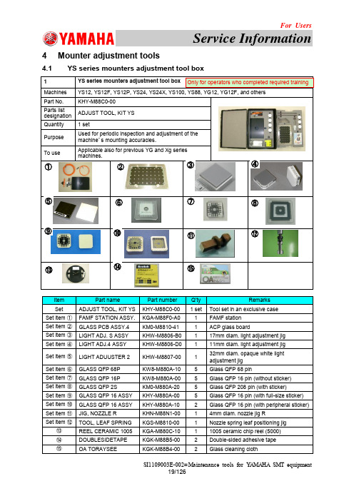
4 Mounter adjustment tools
4.1 YS series mounters adjustment tool box
1
YS series mounters adjustment tool box Only for operators who completed required training
1-④ Machines Part No. Parts list designation Required Q’ty Purpose
To use
11mm diam. light adjustment jig YS12, YS12P, YS24, and YG12, KHW-M8806-D0
Only for operators who completed required training
⑬ ⑭ ⑮
GLASS QFP 68P GLASS QFP 16P GLASS QFP 2S GLASS QFP 16 ASSY GLASS QFP 16 ASSY JIG, NOZZLE R TOOL, LEAF SPRING REEL CERAMIC 1005 DOUBLESIDETAPE OA TORAYSEE
To use
32mm diam. opaque white light adjustment jig Only for operators who completed required training
YS12F, YS24X, YS100, YS88, YG12F, YG100, YG100R, YG88, YG88R, YV100-Xg, YV88-Xg, KHW-M8807-00
pH100操作手册

初始检查
小心地打开包装,检查仪器和配件是否因运输而受损。查看收到的设备是否与装箱 单中的材料列表一致。如发现有损坏或零件不全,请立即通知您的供应商或 YSI 公司。 在证实仪器能正常工作之前,请妥善保存包装材料。
解决方式
• pH 电极截距>1.5pH 或<-1.5pH
• 更换缓冲液和/或 pH 电极,按 退
Er 1 • 电极和自动/手动温度传感器设定在 出键
缓冲液的±1.5pH 范围内之前,按 • 留出足够的时间等待电极和自动/
标准点键
手动温度传感器稳定
• pH 电极受损
• 将仪器送修
• pH 电极斜率偏离超过理想值的 30% • 使用合适的缓冲液,电极斜率偏离
更换电池时,拧下电池盖上的两个螺丝,取下电池盖和密封 圈;更换 9 伏电池;重新装上电池盖和密封圈(正确放置密封圈 确保密封),拧紧电池盖上的螺丝以达到防溅性能。
1
图1 安装电池
按键功能
1. :开机或关机。关机时,仪器的校准值不被清除;仪器 不用时,关机以节省电池;长期存放时请取下电池。
2. MODE(模式):选择显示模式。连续按 模式键 可依次显示 pH-AUTOLOCK(pH 自动锁定)、mV-AUTOLOCK(mV 自动锁定)、 pH 和 mV。改变显示模式不影响校准值。
Er2 • 电极和自动/手动温度传感器设定在 不超过理想值的 30%
PH100中文手册

保修和维修YSIPH100仪器为终端用户保证.因材料和工艺的缺陷自购买之日起保修一年.YSIPH100的传感器和电缆因材料和工艺的缺陷保修期为六个月.在保修期内,YSI将维修和更换,其唯一区别是免费.本保证覆盖的产品由YSI确定.为实现这个保证.写信或打电话给当地的YSI代表,或联系在YELLOWSPRING的用户服务中心.发送产品和购买证明.付费运输到YSI选定的认可的服务中心.完成维修和更换并寄回仪器.付费运输.维修更换的产品原包修期可结算.自维修和更换之日起至少90天.保修的限制本保证不适用于由下列情况造成的损伤和损怀根据YSI出版的指南.错误安装.操作和使用本产品乱用和误用本产品根据YSI出版的指南和标准的工业步骤.维护不当.对本产品的任何不恰当维修在维修中.使用了损坏的和不适当的元件和部件未经YSI批准.修改本产品目录保证书1联系信息 1概述3防溅 3电池安装 3PH100的主要功能 4LCD显示 4操作步骤 4缓冲表选择 4PH校正 5使用PH160电极模拟器 5PH测量 5温度测量 6MV测量 6故障 6技术规范77概述PH100是一个测量PH,MV和温度的精确工具.内置微处理机储存,计算和补偿所有相关于PH 的参数,包括PH电极的温度特性,电极斜率值和缓冲溶液本仪器有IP65防溅包,机械触摸键具有可靠的触摸性和可示进展,使用9V电池当电源恢复时不须校正.仪表的前板有一个大的LCD瞬时显示PH或MV和温度伴随使用者的提示和模式指示,该仪器提示使用者校正和测量步骤.一个AUTOLOCK的特性确保仪器自动感应终点并锁定显示,显示一个测量的终点值.PH100也可以用非自动锁存模式AUTOLOCK和使用者的提示有助于消除在确定PH值和MV值时的大多数错误.完成精确,重复性的.无差错的测量.PH100型可装备有PH,MV,ORP和A TC(自动温度补偿)传感器.其他特征包括电极偏移识别电极斜率识别.电极效率显示.内置缓冲系数,自动或手动温度补偿.长电池寿命和50HZ/60HZ 噪声去除.该仪器可广泛地,容易的用于现场,工业和试验室.初始检查仔细的打开仪器和附件,检查因运输造成的损伤.逐项对比接到的部件和包装清单.如有损伤或丢失迅速通知YSI.在达到满意操作前,保存所有的包装材料.防溅尽管PH100装在防水材料合内,不要在水下使用,防溅合可预防因偶然跌入非腐蚀性溶液造成的永久性损伤.如果仪器被浸入任何溶液,迅速采取下列措施步骤:1.仔细的用蒸馏水冲洗仪器. 冲洗和干燥后,检查和清洁连接器,清除所有可能影响传感器连接的污物.2.待仪器和传感器充分干燥后,重新启动仪器3.在完成步骤1和2后,仪器未有正确功能,通知YSI作可能的维修和更换.电池安装显示屏上开始显示BA T,表明该仪器可正常使用近1小时.当BAT出现在显示屏上,更换电池(看图1)为更换电池,松开两个电池盖的螺丝,取下电池盖和O型圈.更换9V电池.重新放好电池盖和O 型圈(正确排列O型圈确保密封)紧固好电池盖的螺丝.达到防溅性能.PH100的主要功能1.开机和关机.当关机时PH100的校正值不被清除.仪器通电和关机时状态相同.当仪器不用关机以节省电池,长期储存,取下电池.2.MODE:选择显示模式.压MODE可连续显示PH—AUTOLOCK,MV—AUTOLOCK,PH和MV.改变显示模式不影响校正值.3.STAND和SLOPE键.使用仪器的两点PH校正.当开机时.压并持续STAND改变缓冲设置.4.△和▽键.在手动模式(MAN)输入温度值.在操作ATC模式,这些键不能使用.5.MEA./EFF.:当在PH—AUTOLOCK或MV—AUTOLOCK模式的操作中,压此键释放自动锁存状态.压并持续5秒显示电极效率.6.ESC:当一个错误信号出现,压此键可清除.此操作清除所有内存中的校正值.在正常操作中,为防止偶然的清除.该键不响应,除非你压此键并持续性2秒.只有当一个错误信息显示时,使用该键.当压ESC,所有的LCD元件点亮.大约2秒后,仪器进入PH—AUTOLOCK模式.显示“AUTOLOCK”和“STAND”开始闪动指示需要校正.当错误发生.压ESC并重新校正.LCD显示1.WAIT:显示仪器等待稳定读数和终点感应.2.BAT:低电量指示3.ATC/MAN:如果A TC传感器连接,显示“ATC”.否则显示“MAN”4.STAND/SLOPE:如果参数被校正,“STAND”或“SLOPE”保持稳定.如果其中一项未被校正,它将闪动.5.AUTO:自动模式指示6.HOLD:在自动锁存模式中,指示一个冻结的读数7.EFF%:当使用者观察电极效率时显示.当效率低于75%,建议更换电极.8.PH/MV:仪器和模式指示.9.PH,MV和电极效率的主显示10.℃:温度显示.操作步骤缓冲表选择该仪器有2套缓冲设置:7.00,4.01,10.01PH和6.86,4.00,9.18PH.为改变缓冲设置,关机,当再开机时,压并持续按STAND.如果仪器未校正并处于PH模式,它显示“7.00”如果第一套设置击活.如果是第二套,它显示“6.86”.PH值校正PH100仪器使用2—点校正.第一点必须是6.86/7.00缓冲液,第二点或者是4.00/4.01,或者是9.18/10.01。
YSI X100 Series 产品说明书
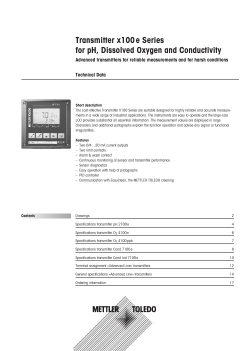
Transmitter x100e Seriesfor pH, Dissolved Oxygen and ConductivityAdvanced transmitters for reliable measurements and for harsh conditions Technical DataDrawings2Specifications transmitter pH 2100e 4Specifications transmitter O 24100e 6Specifications transmitter O 24100ppb 7Specifications transmitter Cond 7100e 8Specifications transmitter Cond Ind 7100e 10Terminal assignment «Advanced Line» transmitters 12General specifications «Advanced Line» transmitters 14Ordering information17Short descriptionThe cost-effective Transmitter X100 Series are suitable designed for highly reliable and accurate measure-ments in a wide range of industrial applications. The instruments are easy to operate and the large-size LCD provides substantial all essential information. The measurement values are displayed in largecharacters and additional pictographs explain the function operation and advise any signal or functional irregularities.Features–Two 0/4…20 mA current outputs –Two limit contacts –Alarm & wash contact–Continuous monitoring of sensor and transmitter performance –Sensor diagnostics–Easy operation with help of pictographs –PID controller–Communication with EasyClean, the METTLER TOLEDO cleaningContentsDrawings AssemblyMounting1Sealing plugs2Hexagon nuts3Pg cable glands4Rubber reducer5Pg plug6Enclosure screws7Hinge pin8Cable ties9Filler plugs10Gaskets11Washer12Jumper876541Cable gland (3 pieces)2Breakthroughs for cablegland or conduit 1/2 ",Ø 21.5 mm(2 breakthroughs).Conduits not included!3Holes for post mounting4Holes for wall mountingDrawingsPipe mounting with ZU 0274 bracket kitProtective hood ZU 0276 for wall and pipe mountingPanel-mount kit ZU 0275165 mm 132 mm173 m m1 Protected hood (if required)2 Hose clamps with worm gear drive to DIN 3017(2 pieces)3 Postmounting plate4 For vertical orhorizontal post/pipe mounting5 Self-tapping screws1 Screws2 Seal3 Control panel4 Span pieces5 Threaded sleevesSpecifications Transmitter pH 2100e pH/mV input Input for pH, ORP electrodes or ISFETMeasurement range –1500…+1500 mVDisplay range pH value –2.00…16.00ORP –1999…+1999 mVGlass electrode input1)Input resistance > 0.5 x 10 12ΩInput current < 2 x 10 –12AReference electrode input1)Input resistance > 1 x 10¹⁰ΩInput current < 1 x 10 –10AMeas. error 1,2,3)pH value< 0.02mV value< 1 mVElectrodestandardization pH *Operating modes-BUF Calibration with automatic buffer recognition Calimatic:Buffer sets-01-Mettler-Toledo 2.00/4.01/7.00/9.21-02-Merck/Riedel de Haen 2.00/4.00/7.00/9.00/12.00-03-Ciba (94) 2.06/4.00/7.00/10.00-04-NIST technical 1.68/4.00/7.00/10.01/12.46-05-NIST standard 1.679/4.006/6.865/9.180-06-HACH 4.00/7.00/10.18-07-WTW technical buffers 2.00/4.01/7.00/10.00-PRD Product Calibration-MAN Calibration with manual entry of individual buffer values-DAT Data entry of premeasured electrodesZero point adjustment ±200 mVMax. calibration range Asymmetry potential: ±60 mVSlope: 80…103 % (47.5…61 mV/pH)Sensor standardizationORP*ORP calibrationMax. calibration range –700…+700D mVCal timer 0000…9999 hSensocheck automatic monitoring of glass andreference electrode (can be disabled)Sensoface provides information on the electrode condition.Evaluation of zero/slope, response,calibration interval, SensocheckSpecifications Transmitter pH 2100e Temperature input *Pt100/Pt1000/NTC 30 kΩ / NTC 8,55 kΩ2-wire connection, adjustableMeasurement range Pt100/Pt1000: –20.0…+ 200.0 °C/–4…+ 392 °FNTC 30 kΩ – 20.0…+ 150.0 °C/–4…+ 302 °FNTC 8.55 kΩ –10.0…+ 130.0 °C/+14…+ 266 °FAdjustment range 10 KResolution0.1 °C/1 °FMeas. error 1,2,3)< 0.5 K (< 1 K for Pt100; <1K for NTC >100 °C)Temp. compensation Linear –19.99…+19.99 %/Kof process medium (reference temp. 25 °C)Power output for operating an ISFET adapter+ 3 V/0.5 mA– 3 V/0.5 mA*User-defined1)To IEC 746 Part 1, at nominal operating conditions2)± 1 count3)Plus sensor errorSpecifications Transmitter O24100e Dissolved oxygen inputSensor type A:InPro6000 (6800)Sensor type B:InPro6900Measuring current-2…1800 nAResolution0.05 nA (with Vpol ≤ 800 mV and Vref ≤ 200 mV)Saturation (–10…80 °C)0…500 %Meas. error1,2,3)0.5 % of meas. val. +0.5 %Concentration (–10…80 °C)0.00…50.00 mg/l0.00…50.00 ppmMeas. error 1,2,3)0.5 % of meas. val. + 0.05 mg/lor 0.05 ppmAdm. guard current20 µAPolarization voltage * 0…1000 mVProcess pressure* 0.000…9.999 bar(…999.9 kPa/…145.0 psi)Salt correction * 00.00…45.00 g/kgSensor standardizationOperating modes * DO saturation (automatic)DO concentration (automatic)Product calibrationZero point calibrationCalibration range Zero point ± 2 nASensor type A Slope 25…130 nA(at 25 °C, 1013 mbars)Calibration range Zero point ± 2 nASensor type B Slope200…550 nA(at 25 °C, 1013 mbars)Calibration timer * 0000…9999 hPressure correction * 0.000…9.999 bars/999.9 kPa/145.0 psiSensocheck Monitoring for short circuits/open circuits (can be disabled)Sensoface Provides information on the sensor conditionEvaluation of zero/slope, response, calibration interval, SensocheckTemperature input *NTC 22 kΩ / NTC 30 kΩ*2-wire connection, adjustableMeasurement range– 20.0…+150.0 °C/– 4…+ 302 °FAdjustment range10 KResolution0.1 °C/1 °FMeas. error 1,2,3)< 0.5 K (< 1 K at >100 °C)*User-defined1)To IEC 746 Part 1, at nominal operating conditions2)± 1 count3)Plus sensor errorSpecifications Transmitter O24100ppb Dissolved oxygen inputSensor type A:InPro6000 (6800)Sensor type B:InPro6900Measuring current-2…600 nAResolution0.01 nA (with Vpol ≤ 500 mV and Vref ≤ 200 mV)Saturation (–10…80 °C)0.0.…120.0 %Meas. error1,2,3)0.5 % of meas. val. +0.1 %Concentration (–10…80 °C)0000…9999 µg/l0000…9999 ppb0.0000…9.999 mg/l0.0000…9.999 ppmMeas. error 1,2,3)0.5 % of meas. val. +0.005 mg/lor 0.005 ppmAdm. guard current20 µAPolarization voltage* 0…1000 mVProcess pressure* 0.000…9.999 bars(to 999.9 kPa/…145.0 psi)Salt correction* 00.00…45.00 g/kgSensor standardizationOperating modes * DO saturation (automatic)DO concentration (automatic)Product calibrationZero point calibrationCalibration range Zero point ± 2 nASensor type A Slope25…130 nA(at 25 °C, 1013 mbars)Calibration range Zero point ± 2 nASensor type B Slope 200…550 nA(at 25 °C, 1013 mbars)Calibration timer * 0000…9999 hPressure correction * 0.000…9.999 bars/999.9 kPa/145.0 psiSensocheck Monitoring for short circuits/open circuits (can be disabled)Sensoface Provides information on the sensor conditionEvaluation of zero/slope, response, calibration interval, SensocheckTemperature input *NTC 22 kΩ/ NTC 30 kΩ*2-wire connection, adjustableMeasurement range–20.0…+150.0 °C/–4…+302 °FAdjustment range10 KResolution0.1 °C/1 °FMeas. error 1,2,3)< 0.5 K (< 1 K at >100 °C)*User-defined1)To IEC 746 Part 1, at nominal operating conditions2)± 1 count3)Plus sensor errorSpecifications Transmitter Cond 7100e Conductivity input Input for 2-e or 4-e conductivity sensorsWorking range4-electrode sensor:0.2 µS *c …1000 mS * c (c = cell constant)2-electrode sensor:0.2 µS *c …200 mS * c(the actual range is very much depending on the sensor used,display limited to 3500 mS)Effective ranges Conductivity0.000…9.999 µS/cm00.00…99.99 µS/cm000.0…999.9 µS/cm0000…9999 µS/cm0.000…9.999 mS/cm00.00…99.99 mS/cm000.0…999.9 mS/cm0.000…9.999 S/m00.00…99.99 S/mResistivity00.00…99.99 MΩcmConcentration0.00…9.99 % by wt.Salinity0.0…45.0 ‰ (0…35 °C)Measurement error1,2,3)< 1% of measured value +0.4 µS * cConc. measurements-01- NaCl0.00…9.99 % by wt.(0 …60°C)-02- HCl0.00…9.99 % by wt.(–20…50 °C)-03- NaOH0.00…9.99 % by wt.(0…100 °C)-04- H2SO40.00…9.99 % by wt.(–17…110 °C)-05- HNO30.00…9.99 % by wt.(–17…50 °C)Sensor standardization Input of cell constant with simultaneous displayof conductivity value and temperatureInput of conductivity value with simultaneous displayof cell constant and temperatureProduct calibrationTemperature probe adjustmentPermissible cell constant00.0050…19.9999 cm–1Sensocheck Monitoring of sensor polarization and cable capacitance (can be disabled)Sensoface Provides information on the sensor condition (Sensocheck)Sensor monitor Display of direct measurement values for validationpurpose (resistance/temperature)USP-Function Monitoring of conductivity of water for pharmaceuticalapplications to USP (USP <645>) with adjustable limitvalues (10…100 % of USP value)Specifications Transmitter Cond 7100e Temperature input*)Pt100/Pt1000/NTC 30 kΩ / NTC 8.55 kΩ2-wire connection, adjustableMeasuring range Pt100/Pt1000–20…+200 °C / –4…+392 °FNTC 30 kΩ–20…+150 °C / -4…+302 °FNTC 8.55 kΩ–10…+130 °C / +14…+266 °FResolution0.1 °C / 1 °FError1,2,3)0.5 K (< 1 K with Pt100; < 1 K with NTC > 100 °C)Temperature compensation(OFF)not compensated(ref. temp. 25 °C)(Lin)linear, 0.00…19.99 %/K, –20…130 °C(NLF)natural waters to EN 27888, 0…36 °C(nACL)ultrapure water with NaCl traces, 0…120 °C(HCL)ultrapure water with HCl traces, 0…120 °C(nH3)ultrapure water with NH3traces, 0…120 °C*User-defined1)To IEC 746 Part 1, at nominal operating conditions2)± 1 count3)Plus sensor errorSpecifications Transmitter Cond Ind 7100e Conductivity input Input for inductive sensorsWorking range Conductivity0.000…1999 mS/cmConcentration0.00…100 % by wt.Salinity0.0…45.0 ‰ (0…35 °C)Effective ranges Conductivity0.000…9.999 mS/cm00.00…99.99 mS/cm000.0…999.9 mS/cm0000…1999 mS/cm0.000…9.999 S/m00.00…99.99 S/mConcentration0.00…99.99 %Salinity0.0…45.0 ‰ (0…35 °C)Measurement error1,2,3)< 1% of measured value +0.005 mSConc. measurements-01- NaCl0…26 %(0…60 °C)-02- HCl0…18 % (–20…50 °C)-03- NaOH0…14 % (0…100 °C)-04- H2SO40…30 % (–17…110 °C)-05- HNO30…30 % (–20…50 °C)-06- H2SO492…99 % (–17…115 °C)-07- HCl22…39 % (–20…50 °C)-08- HNO335…96 % (–20…50 °C)-09- H2SO432…84 % (–17…115 °C)-10- NaOH18…50 % (0…100 °C)Sensor standardization Input of cell factor with simultaneous displayof conductivity value and temperatureInput of conductivity value with simultaneous displayof cell factor and temperatureProduct calibrationZero point calibrationTemperature probe adjustmentPermissible cell factor00.100…19.999Permissible transfer ratio01.00…199.99Permissible zero pointdeviation± 0.5 mS/cmSensocheck Monitoring of sender coil and leads for short circuiting,and of the receiver coil for disruption (can be disabled)Sensoface Indicates sensor status (zero point, sensocheck)Sensor monitor Display of direct measurement values for validationpurpose (resistance /temperature)Specifications Transmitter Cond Ind 7100e Temperature input*Pt100/Pt1000/NTC 100 kΩ2-wire connection, adjustableMeasuring range Pt100/Pt1000–20…+200 °C / –4… +392 °FNTC–20…+130 °C / –4… +266 °FResolution0.1 °C / 1 °FError1,2,3)0.5 K (< 1 K with Pt100; < 1 K with NTC > 100 °C)Temperature compensation(OFF)not compensated(ref. temp. 25 °C)(LIN)linear, 0.00…19.99 %/K(NLF)natural waters to EN 27888 (0…35 °C)* User-defined1) To IEC 746 Part 1, at nominal operating conditions2) ± 1 count3) Plus sensor errorTerminal assignment «Advanced Line» transmittersTransmitter O 24100 ppbTransmitter O 24100 eTransmitter pH 2100 eTerminal assignment«Advanced Line» transmitters Transmitter Cond 7100eTransmitter Cond Ind 7100eGeneral specifications «Advanced Line» transmitters HOLD input Galv. separated (OPTO coupler)Function Switches device to HOLD stateSwitching voltage 0…2 V (AC/DC) hold inactive10…30 V (AC/DC) hold activeCONTROL input pH/O2)Galv. separated (OPTO coupler)Function Control input for automatic cleaning/calibration systemSwitching voltage0…2 V (AC/DC) inactive10…30 V (AC/DC) activeCONTROL input (Cond)Galv. separated (OPTO coupler)Function Switches between two parameter setsSwitching voltage0…2 V (AC/DC) set #1 active10…30 V (AC/DC) set #2 activeOutput 10/4…20 mA, max. 10 V, floating(galv. connected to output 2)Process variable *pH 2100 e pH/mVO24100e%, mg/lO24100 ppb%, mg/lCond 7100e conductivity, resistivity, concentration, salinityCond Ind 7100e conductivity, concentration, salinityCurrent characteristics*linear or logarithmic (depends on transmitter)Overrange *22 mA in the case of error messageOutput filter *Low-pass, filter time constant 0…120 sMeas. error1)< 0.3 % of current value +0.05 mAStart/end of scale As desired within measuring rangeAdm. span pH 2100e 2.00…18.00/200…3000 mV024100e 5…500 %, 0.5…50 mg/l024100 ppb 2…200 %, 0.2…10 mg/lCond 7100e LIN 5 % of selected measuring rangeLOG 1 decadeCond Ind 7100e LIN 5 % of selected measuring rangeLOG 1 decadeOutput 20/4…20 mA, max. 10 V, floating(galv. connected to output 1)Process variable TemperatureOverrange *22 mA in the case of temp error messagesOutput filter *Low-pass, filter time constant 0…120 sMeas. error 1)< 0.3 % of current value + 0.05 mAStart/end of scale *pH, Cond: –20…+200 °C/–4…+392 °F, 02:–20…+150 °C/–4...+302 °FAdm. span pH, Cond: 20…320 K, 02:20…170 KAlarm contact Relay contact, floatingContact ratings AC < 250 V/< 3 A/< 750 VADC < 30 V/< 3 A/< 90 WContact response N/C (fail-safe type)Alarm delay 0000…0600 sGeneral specifications «Advanced Line» transmitters Limit values Output via relay contacts R1, R2Contacts R1, R2 floating, but inter-connectedContact ratings AC < 250 V/< 3 A/< 750 VADC < 30 V/< 3 A/< 90 WContact response *N/C or N/ODelay *0000…9999 sSwitching points *As desired within measuring rangeHysteresis *pH 2100e0…5.00 pH/0…500 mV024100e 0…50 %/0…5.00 mg/l (ppm)024100ppb 0…50 %/0…5.00 mg/l (ppm)Cond 7100e0…50 % of measuring rangeCond Ind 7100e0…50 % of measuring rangePID process controller Output via relay contacts R1, R2 (see limit values)Setpoint specification *pH 2100e–02.00…16.00/– 1500…+1500 mV024100e 0…500 % / 0…50 mg/l024100ppb 0…120% / 0…9.999 mg/lCond 7100e within selected measuring rangeCond Ind 7100e within selected measuring rangeNeutral zone *pH 2100e0…5.00 pH / 0…+500 mV024100e 0…50 % / 0…5 mg/l024100ppb 0…50 % / 0…5 mg/l (ppm)Cond 7100e within selected measuring rangeCond Ind 7100e max. 50 % of selected measuring rangeP-action *Controller gain K R:0010…9999 %I-action component *Reset time Tr: 0000…9999 s(0000 s = no integral action)D-action component *Derivative-actiontime Td: 0000…9999 s(0000 s = no derivative action)Controller type*Pulse length controller or pulse frequency controllerPulse period *0001…0600 s, min. ON time 0.5 s (pulse length controller)Max. pulse frequency *0001…0180 min–1(pulse frequency controller)Cleaning function/Relay contact, floating2nd parameter set for controlling a simple rinsing system or an automatic cleaning systemor to show that 2nd parameter set is activeContact ratings AC < 250 V/< 3 A/< 750 VADC < 30 V/< 3 A/< 90 WContact response *N/C or N/O (cleaning function)N/O (2nd parameter set)Rinsing interval *000.0…999.9 h(000.0 h = cleaning function switched off)Cleaning time *0000…1999 sCalibration interval *000.0…999.9 hCleaning interval*000.0…999.9 h*User-defined1)To IEC 746 Part 1, at nominal operating conditions2)± 1 count3)Plus sensor errorGeneral specifications«Advanced Line» transmitters Display LC display, 7-segment with iconsMain display Character height 17 mm, unit symbols 10 mmSecondary display Character height 10 mm, unit symbols 7 mmSensoface 3 status indicators (friendly, neutral, sad smiley)Mode indicators 5 status bars: «meas», «cal», «alarm», «cleaning», «config»18 further icons for configuration and messagesAlarm indication Red LED in case of alarm or HOLD, user definedKeypad 5 keys: [cal] [conf] [] [] [enter]Service functionsCurrent source Current specifiable for output 1 and 2 (00.00…22.00mA)Manual controller Controller output entered directly (start of control process)Device self-test Automatic memory test (RAM, FLASH, EEPROM)Display test Display of all segmentsLast Error Display of last error occurredSensor monitor Display of direct, uncorrected sensor signal (electrode/sensor)Relay test Manual control of the four switching contactsParameter sets*Two selectable parameter sets for different applicationsData retention Parameters and calibration data > 10 years (EEPROM)EMC EN 61326EN 61326/A1Lightning protection EN 61000-4-5, Installation Class 2Protection against Protective separation of all extra-low-voltageelectrical shock circuits against mains as per EN 61010FM/CSA NI, Class 1, Div 2, Group A, B, C, D, T4Power supply24 (–15%)…230 (+10%) V AC/DC; approx. 5 VA, 2.5 WAC: 45…65 HzOvervoltage category II, Class IINominal operating conditionsAmbient temperature– 20…+55 °C / –4...+131 °FTransport/Storage temp – 20…+70 °C / -4...+158 °FRelative humidity 10…95 % non condensingPower supply24 (–15%)…230 (+ 10 %) V AC/DCFrequency for AC 45…65 HzGeneral specifications and ordering information«Advanced Line» transmittersEnclosure molded enclosure made of PBT (polybutylene terephtalate)Color Bluish gray RAL 7031Assembly• Wall mounting• Pipe mounting: Ø 40…60 mm,Ø 30…45 mm• Panel mounting, cutout to DIN 43 700, sealed against panelDimensions H x W x L: 144 x 144 x 105 mm (5.67 x 5.67 x 4.13")Ingress protection IP 65/NEMA 4XCable glands 3 breakthroughs for cable glands M20 x 1.52 breakthroughs for NPT 1/2 " or Rigid Metallic ConduitWeight approx. 1 kg*User-defined1)To IEC 746 Part 1, at nominal operating conditions2)± 1 count3)Plus sensor errorOrdering information Array Transmitter pH 2100e pH 2100e52 121 102Transmitter O24100e O24100e52 121 103Transmitter O2 4100ppb O24100ppb52 121 104Transmitter Cond 7100e Cond 7100e52 121 126Transmitter Cond Ind 7100e Cond Ind 7100e52 121 127Installation accessoriesBracket kit ZU 027452 120 741Panel-mount kit ZU 027552 120 740Protective hood ZU 027652 120 739NotesNotesMETTLER TOLEDO Market Organizations Subject to technical changes.© Mettler-Toledo AG, Process Analytics 08/13 Printed in Switzerland. 52 121 132Mettler-Toledo AG, Process Analytics Im Hackacker 15, CH–8902 Urdorf Tel. + 41 44 729 62 11, Fax +41 44 729 66 Sales and Service:Australia Mettler-Toledo Ltd.220 Turner Street Port Melbourne AUS-3207 Melbourne/VIC Phone +61 1300 659 761Fax +61 3 9645 3935e-mail *****************Austria Mettler-Toledo Ges.m.b.H.Südrandstraße 17A-1230 Wien Phone +43 1 604 19 80Fax +43 1 604 28 80e-mail ***********************Brazil Mettler-Toledo Ind. e Com. Ltda.Avenida Tamboré, 418TamboréBR-06460-000 Barueri/SP Tel.+55 11 4166 7400Fax +55 11 4166 7401e-mail *******************.br *******************.br China Mettler-Toledo Instruments (Shanghai) Co. Ltd.589 Gui Ping Road Cao He Jing CN-200233 Shanghai Phone +86 21 64 85 04 35Fax +86 21 64 85 33 51e-mail *************** Croatia Mettler-Toledo d.o.o.Mandlova 3HR-10000 Zagreb Phone +385 1 292 06 33Fax +385 1 295 81 40e-mail ****************Czech Republic Mettler-Toledo s.r.o.Trebohosticka 2283/2CZ-100 00 Praha 10 Phone +420 2 72 123 150Fax +420 2 72 123 170e-mail *****************Denmark Mettler-Toledo A/S Naverland 8DK-2600 Glostrup Phone +45 43 27 08 00Fax +45 43 27 08 28e-mail ****************France Mettler-Toledo Analyse Industrielle S.A.S.30, Boulevard de Douaumont F-75017 Paris Phone +33 1 47 37 06 00Fax +33 1 47 37 46 26e-mail **************Germany Mettler-Toledo GmbH Prozeßanalytik Ockerweg 3D-35396 Gießen Phone +49 641 507 333Fax +49 641 507 397e-mail **************Great Britain Mettler-Toledo LTD 64 Boston Road, Beaumont Leys GB-Leicester LE4 1AW Phone +44 116 235 7070Fax +44 116 236 5500e-mail *******************Hungary Mettler-Toledo Kereskedelmi KFT Teve u. 41HU-1139 Budapest Phone +36 1 288 40 40Fax +36 1 288 40 50e-mail ***************India Mettler-Toledo India Private Limited Amar Hill, Saki Vihar Road Powai IN-400 072 Mumbai Phone +91 22 2857 0808Fax +91 22 2857 5071e-mail *****************Italy Mettler-Toledo S.p.A.Via Vialba 42I-20026 Novate Milanese Phone +39 02 333 321Fax +39 02 356 2973e-mail **************************Japan Mettler-Toledo K.K.Process Division 6F Ikenohata Nisshoku Bldg.2-9-7, Ikenohata Taito-ku JP-110-0008 Tokyo Phone +81 3 5815 5606Fax +81 3 5815 5626e-mail **********************Malaysia Mettler-Toledo (M) Sdn Bhd Bangunan Electroscon Holding, U 1-01Lot 8 Jalan Astaka U8/84Seksyen U8, Bukit Jelutong MY-40150 Shah Alam Selangor Phone +60 3 78 44 58 88 Fax +60 3 78 45 87 73e-mail ****************************Mexico Mettler-Toledo S.A. de C.V.Ejercito Nacional #340Col. Chapultepec Morales Del. Miguel Hidalgo MX-11570 México D.F.Phone +52 55 1946 0900e-mail *****************Poland Mettler-Toledo (Poland) Sp.z.o.o.ul. Poleczki 21PL-02-822 Warszawa Phone +48 22 545 06 80Fax +48 22 545 06 88e-mail *************Russia Mettler-Toledo Vostok ZAO Sretenskij Bulvar 6/1Office 6RU-101000 Moscow Phone +7 495 621 56 66Fax +7 495 621 63 53e-mail **************Singapore Mettler-Toledo (S) Pte. Ltd.Block 28Ayer Rajah Crescent #05-01SG-139959 Singapore Phone +65 6890 00 11Fax +65 6890 00 12+65 6890 00 13e-mail ****************Slovakia Mettler-Toledo s.r.o.Hattalova 12/A SK-83103 Bratislava Phone +421 2 4444 12 20-2Fax +421 2 4444 12 23e-mail *************Slovenia Mettler-Toledo d.o.o.Pot heroja Trtnika 26SI-1261 Ljubljana-Dobrunje Phone +386 1 530 80 50Fax +386 1 562 17 89e-mail *******************South Korea Mettler-Toledo (Korea) Ltd.Yeil Building 1 & 2 F 124-5, YangJe-Dong SeCho-Ku KR-137-130 Seoul Phone +82 2 3498 3500Fax +82 2 3498 3555e-mail *****************Spain Mettler-Toledo S.A.E.C/Miguel Hernández, 69-71ES-08908 L’Hospitalet de Llobregat (Barcelona)Phone +34 902 32 00 23Fax +34 902 32 00 24e-mail *************Sweden Mettler-Toledo AB Virkesvägen 10Box 92161SE-12008 Stockholm Phone +46 8 702 50 00Fax +46 8 642 45 62e-mail ****************Switzerland Mettler-Toledo (Schweiz) GmbH Im Langacher Postfach CH-8606 Greifensee Phone +41 44 944 45 45Fax +41 44 944 45 10e-mail ******************Thailand Mettler-Toledo (Thailand) Ltd.272 Soi Soonvijai 4Rama 9 Rd., Bangkapi Huay Kwang TH-10320 Bangkok Phone +66 2 723 03 00Fax +66 2 719 64 79e-mail ****************************USA/Canada Mettler-Toledo Ingold, Inc.36 Middlesex Turnpike Bedford, MA 01730, USA Phone +1 781 301 8800Freephone +1 800 352 8763Fax +1 781 271 0681e-mail**************。
萤石 环境健康-净水器 CS-ES100T 使用说明书

净水器用户指南使用产品前,请仔细阅读用户指南,并妥善保管目录一、用户必读 (3)二、装箱清单 (3)三、产品功能 (4)1.产品适用范围 (4)2.过滤性能 (4)3.规格参数 (4)四、产品结构 (5)1.外观介绍 (5)五、首次使用说明 (5)六、操作界面 (6)1.取水键 (7)2.童锁功能 (7)3.标准水量 (7)4.模式调节 (7)5.待机状态 (7)6.外水箱补水 (7)7.内水箱缺水补水状态 (8)8.滤芯更换及复位说明 (8)9.屏幕显示指南 (9)八、清洗保养 (9)九、故障诊断 (10)十、安全注意事项 (10)十一、限制物质或元素标识表 (11)十二、售后服务支持 (12)十三、产品保修声明 (13)十四、版权声明 (14)一、用户必读用户必须严格按照本《净水器用户指南》(后简称用户指南)中所阐述的安装规范操作,并按照用户指南中的使用方法使用净水器。
否则,对于一切因未按照用户指南规定安装、使用净水器而引起净水器损坏或漏水而造成的财产损失,甚至人身伤害,本公司不承担任何经济和法律责任。
以下情况请勿使用此产品:●发现净水器已有损坏;●发现插头或电源线有损坏;●发现净水器不断有水溢出;注意:●定期检查电源、电线是否松脱损坏,避免漏电造成重大事故。
●不得擅自拆开或改装净水器,可能会导致故障或漏水造成财产损失。
●任何因不当使用所造成的故障,将不在保修范围内。
●拔掉插头时请不要强拉电源线。
二、装箱清单产品包装盒中包含的产品和配件信息如下图所示:1.产品适用范围适用水质:市政自来水2.过滤性能3.规格参数1.外观介绍五、首次使用说明六、操作界面●操作界面:●显示界面:七、使用说明1.取水键待机时蓝色灯光亮起,选择水温水量后,点击取水键,白色灯光亮起,设备出水,再次点击停止取水。
2.童锁功能选择热水时,需要先长按1秒,解锁后,才能出水。
临时解锁后,10秒内无操作设备自动上锁。
3.标准水量点击标准水量,指示灯亮起,点击取水键,单次出水240ml后会自动停止出水。
YS系列录波装置管理分析软件使用说明书
- 航天银山YS系列录波装置管理分析软件使用说明书南京航天银山电气有限公司2011年1月目录1.软件安装与运行 (3)1.1软件的安装及配置 (3)1.2运行主界面 (4)2.功能菜单说明 (8)系统菜单 (9)参数菜单 (12)通讯 (13)分析 (17)长态录波功能 (30)窗口菜单 (32)帮助菜单 (32)3.参数设置 (33)3.1 YS900参数设置 (33)3.2 YS36参数设置 (44)3.3 YS8A参数设置 (50)3.4 YS88A参数设置 (52)3.5 YS89参数设置 (55)3.6 YS89A参数设置 (60)3.7 YS89A+参数设置 (66)3.8 YS901参数设置 (66)1软件安装与运行YS系列录波装置管理分析软件是实现对本公司各种型号故障录波装置进行统一综合管理和分析的后台软件。
该软件可通过网络通讯连接各种型号的故障录波装置,完成对录波装置的参数维护设置、录波文件传输、故障文件显示、分析、打印、录波装置运行监视等功能。
可以安装在变电站的监控室中或和录波装置单元组屏安装,也可以安装在远程的调度大楼中。
根据软件安装的位置和管辖的范围,软件分成了两个使用版本,主站和子站。
对于主站版本,软件可以管理多个变电站内的录波装置,子站版本一般安装在某个变电站内管理本站中的1台或多台录波装置。
主站版本和子站版本的软件在使用和实际功能上基本没有差别,只是在某些配置功能上有一些区别。
目前软件支持的接入录波装置型号有:YS8A、YS88A(YS88)、YS89(YS201)、YS89A(YS201A)、YS89A+、YS900A(YS900B)、YS900A(66KV)、YS36(YS36G)、YS901等。
针对不同型号的录波装置,某些具体的应用或通讯功能可能会不同,软件中对于装置不支持的功能将通过使菜单或工具条或选项等控制窗口无效来实现。
1.1软件安装及配置在线软件的安装通常情况下在机器出厂时已完成,在现场一般只做软件升级。