安科瑞 AFRD系列防火门监控系统安装使用说明书_V1.2_
安科瑞电动机保护器监控系统说明书免费下载

282AFRD-CB(YT)型一体式常闭防火门监控模块使用说明

主体底盖
主体底盖
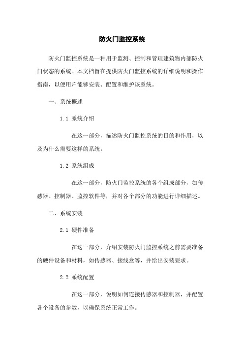
AFRD-CB2(YT)型: 安装时,仍保持门扇处于关闭状态,将一体式监控模块的主体底盖进行接线后,水平居中放置于
门框顶部上方距门框顶部边界约 3mm 处。拧紧螺丝固定后,然后双手拿一体式监控模块主体上盖的两 边,与底盖水平对齐,上盖最左边与底盖最左边对齐后稍用劲将上盖嵌入底盖卡槽,在确认上盖嵌入 卡槽后,往右移动上盖完成模块的合体安装。最后将防火门磁铁水平放置于门框顶部下方,将磁铁的 感应条与监控模块主体的感应条垂直对齐,上下间距不超过 1cm。
5、产品接线 5.1 接线端子图
5.2 通讯接线 监控模块提供二总线通讯接口,各种数据信息均可在通讯线路上传送。每个监控模块均可设定
其通讯地址。二总线通讯连接线建议使用两芯屏蔽线(ZRNH-RVSP-2×2.5mm²),布线时应使通讯线远 离强电电缆或者其它强电磁环境。 6、产品设置要求 6.1 指示显示及操作
上,拧紧螺丝固定。然后双手拿一体式监控模块主体上盖的两边,与底盖水平对齐,上盖最左边与底
盖最左边对齐后稍用劲将上盖嵌入底盖卡槽,在确认上盖嵌入卡槽后,往右移动上盖完成模块的合体 安装。最后将防火门磁铁水平放置于门框顶部下方,将磁铁的感应条与监控模块主体的感应条垂直对 齐,上下间距不超过 1cm。
主体上盖
指示灯:监控模块有运行指示灯(绿色)、通讯指示灯(绿色)以及故障指示灯(黄色)。当设备 正常运行时,运行指示灯闪烁;当设备与监控器或区域分机正常进行二总线通讯时,通讯指示灯闪烁; 当出现通讯故障或常闭防火门处于非正常打开状态时,故障指示灯点亮。 6.2 通讯设置
监控模块的波特率为固定值 19200bps,通讯地址是通过编码器来设置的,应在安装前预先设置 通讯地址 7、模块自身故障分析
Acrel-6000型电气火灾监控设备-安科瑞电气

084Acrel-6000型电气火灾监控设备安装使用说明书V1.2江苏安科瑞电器制造有限公司Jiangsu Acrel Electric MFG.Co.,Ltd.危险和警告本设备只能由专业人士进行安装和维护,对于因不遵守本手册说明进行的违规操作所引起的故障,厂家将不承担任何责任。
触电、燃烧或爆炸的危险设备只能由取得资格的工作人员才能进行安装和维护。
对设备进行维护操作前,应隔离电源供应。
要用一个合适的电压检测设备来确认电压已切断。
在将设备通电前,应将所有的部件恢复原位。
设备在使用中应提供正确的额定电压。
不注意这些预防措施可能会引起严重伤害。
申明:版权所有,未经本公司之书面许可,此手册中任何段落,章节内容均不得被摘抄、拷贝或以任何形式复制、传播,否则一切后果由违者自负。
本公司保留一切法律权利。
本公司保留对本手册所描述之产品规格进行修改的权利,恕不另行通知。
订货前,请垂询当地代理商以获悉本产品的最新信息。
目录1.概述 (3)2.基本功能 (3)2.1.监控报警功能 (3)2.2.控制输出功能 (3)2.3.故障报警功能 (3)2.4.自检功能 (3)2.5.报警记录存储查询功能 (3)2.6.电源功能 (3)2.7.对探测器控制功能 (3)2.8.权限控制功能 (4)3.主要技术参数 (4)3.1.电源 (4)3.2.工作制 (4)3.3.通讯方式 (4)3.4.监控容量 (4)3.5.监控报警项目 (4)3.6.故障报警项目 (4)3.7.控制输出 (4)3.8.自检项目 (5)3.9.历史记录 (5)3.10.操作分级 (5)3.11.使用环境条件 (5)4.主要组成部件 (5)4.1.面板元件布置及功能说明 (5)5.安装与调试 (7)5.1.系统示意图 (7)5.2.设备安装 (7)5.2.1.环境 (7)5.2.2.安装位置 (7)5.2.3.设备尺寸 (7)5.3.接线 (8)5.4.单机调试 (9)5.5.系统调试 (9)6.使用说明 (10)6.1.软件安装 (10)6.2.数据库配置 (13)6.3.软件的启动与登录 (13)6.4.软件运行界面 (14)6.5.主页面操作 (15)6.5.1.登录与注销 (15)6.5.2.复位 (15)6.5.3.消声 (15)6.5.4.报警列表、故障列表 (15)6.5.5.状态指示灯 (15)6.6.状态页面 (15)6.6.1.单个探测器的数据刷新、复位与参数设置 (16)6.7.列表页面 (17)6.8.网络页面 (18)6.9.事件页面 (19)6.10.自检页面 (20)6.11.维护页面 (21)6.11.1.用户管理 (21)6.11.2.串口配置 (21)6.11.3.探测器配置 (22)6.11.4.设备检测 (22)7.用户须知 (23)注意:本说明书针对Acrel-6000/B型电气火灾监控设备及系统软件的使用进行全面介绍,用户使用前应仔细阅读,充分理解设备及系统软件的各项功能,以便正确、规范操作。
防火门监控系统调试培训手册

AFRD100/B型防火门监控系统调试培训手册版本号发布日期编制人内容V1.0 初稿目录1.概述12.设备及元件12.1.门磁开关12.2.电磁释放器22.3.电动闭门器32.4.防火门监控模块42.5.集中电源62.6.区域分机72.7.防火门监控主机82.8.元件配置一览表92.9.图例符号92.10.布置图例102.11.通讯结构拓扑103.现场施工检查104.监控模块调试114.1.准备114.2.复查124.3.编码器开机124.4.读模块信息124.5.修改模块信息124.6.关机124.7.监控模块设备类型表124.8.注意事项125.集中电源调试135.1.接线复查135.2.故障告警135.3.主备电源切换135.4.调试记录136.区域分机调试136.1.接线复查136.2.故障告警136.3.主备电源切换136.4.调试记录137.监控器配置和调试137.1.概述137.2.通道、回路含义137.3.调试准备147.4.接线复查147.5.监控主机配置147.5.1.开机启动147.5.2.退出系统147.5.3.配置数据库167.5.4.用户管理177.5.5.分机配置187.5.6.通道配置187.5.7.模块配置197.5.8.事件信息207.5.9.IP地址配置207.5.10.运行参数217.6.监控主机调试227.6.1需具备的条件227.6.2自检测试227.6.3通讯调试227.6.4门开/闭状态对位、门关闭未到位报警、常开门手动关闭247.6.5故障报警247.6.6常开门联动关闭测试247.6.7主备电源切换247.6.8监控模块启动/复位控制247.6.9闭门器开启力测定258.监控软件使用说明258.1.开机运行258.2.主页面268.3.状态页面278.4.列表页面288.5.事件页面298.6.自检页面298.7.维护页面308.7.1用户管理308.7.2通道配置308.7.3监控模块配置306.7.4. 设备检测319.附件2 防护门监控器功能319.1.监控报警功能319.2.控制输出功能319.3.故障报警功能329.4.自检功能329.5.报警记录存储查询功能329.6.电源功能329.7.对监控模块控制功能329.8.权限控制功能3210.附件3 主要技术参数3210.1.电源3210.2.工作制3210.3.通讯方式3210.4.监控容量3210.5.监控报警项目3210.6.故障报警项目3210.7.控制输出3310.8.自检项目3310.9.事件记录3310.10.操作分级3310.11.使用环境条件331. 概述AFRD100/B防火门监控系统是安科瑞自主研发的集监视、控制、告警、管理于一体的计算机监控系统,该系统适用于商业综合体、办公楼、商住楼、医院、学校、体育馆、展览馆、星级酒店、机场、轨道交通、隧道、客运枢纽等民用建筑。
安科瑞AFRD系列防火门监控模块安装使用说明书_V1.0_

199AFRD系列防火门监控模块安装使用说明书V1.0江苏安科瑞电器制造有限公司Jiangsu Acrel Electric MFG. Co., Ltd.目录1 概述 (1)2 型号规格 (1)3 技术参数 (1)4 产品外形 (1)4.1 外形尺寸 (1)4.1.1 一体式防火门监控模块(AFRD-CB1/2(YT)型) (1)4.1.2 分体式防火门监控模块 (2)4.2 安装方式 (2)4.2.1一体式防火门监控模块(适用于AFRD-CB1/2(YT)型) (2)4.2.2分体式防火门监控模块(适用于AFRD-CK1/2型、AFRD-CB1/2型) (3)5 产品接线 (4)5.1 接线端子定义 (4)5.1.1 一体式防火门监控模块(适用于AFRD-CB1/2(YT)型) (4)5.1.2 分体式防火门监控模块(适用于AFRD-CK1/2型、AFRD-CB1/2型) (4)5.2 通讯接线 (5)6 产品设置要求 (5)6.1 指示显示及操作 (5)6.2通讯设置 (5)7模块自身故障分析 (5)8 安装要求 (5)9 注意事项 (5)10 配套附件 (6)10.1 AFRD-MC 门磁开关 (6)10.1.1 功能特性 (6)10.1.2外形尺寸 (6)10.2 AFRD-BMQ电动闭门器 (6)10.2.1功能特性 (6)10.2.2 外形尺寸 (6)10.2.3 电动闭门器规格 (6)10.3 AFRD-DC电磁释放器 (7)10.3.1 产品特性 (7)10.3.2 外形尺寸 (7)1概述AFRD系列防火门监控模块分为一体式防火门监控模块和分体式防火门监控模块。
一体式防火门监控模块可监控常闭防火门的工作状态和故障信号,并通过二总线将状态信息上传给防火门监控器或区域分机。
分体式防火门监控模块分为AFRD-CK型常开防火门监控模块和AFRD-CB型常闭防火门监控模块两大类。
其中,AFRD-CK型常开防火门监控模块能够监控常开防火门的电动闭门器、电磁释放器及门磁开关的工作状态,并通过二总线将状态信息上传给防火门监控器或区域分机,当收到火灾报警信号时,将防火门监控器的指令传递给电动闭门器或电磁释放器,从而关闭常开防火门,隔离火源与烟雾,保障生命与财产安全。
安科瑞HD-DVR系列高清录像机使用说明书

Multilingual VersionEnglish中文HD VIDEO RECORDERSERIESUser ManualPlease read instructions thoroughly before operation and retain it for future reference.Online manual download: /user/h0401.swfAll lead-free products offered by the company comply with the requirements of theEuropean law on the Restriction of Hazardous Substances (RoHS) directive, which meansour manufacture processes and products are strictly “lead-free” and without the hazardoussubstances cited in the directive.The crossed-out wheeled bin mark symbolizes that within the European Union the productmust be collected separately at the product end-of-life. This applies to your product andany peripherals marked with this symbol. Do not dispose of these products as unsortedmunicipal waste. Contact your local dealer for procedures for recycling this equipment.This is a class A product. In a domestic environment this product may cause radiointerference in which case the user may be required to take adequate measures.Federal Communications Commission Interference StatementThis equipment has been tested and found to comply with the limits for a Class A digital device, pursuant to Part 15 of the FCC Rules. These limits are designed to provide reasonable protection against harmful interference when the equipment is operated in a commercial environment. This equipment generates, uses, and can radiate radio frequency energy and, if not installed and used in accordance with the instruction manual, may cause harmful interference to radio communications. Operation of this equipment in a residential area is likely to cause harmful interference in which case the user will be required to correct the interference at his own expense.This device complies with Part 15 of the FCC Rules. Operation is subject to the following two conditions:(1) This device mat not cause harmful interference, and(2) This device must accept any interference received, including interference that may cause undesiredoperation.DisclaimeriPad and iPhone are trademarks of Apple Inc., registered in the U.S. and other countries. App Store is a service mark of Apple Inc.IOS is a trademark or registered trademark of Cisco in the U.S. and other countries and is used under license. Google Play and Android are trademarks of Google IncWe reserve the right to revise or remove any content in this manual at any time. We do not warrant or assume any legal liability or responsibility for the accuracy, completeness, or usefulness of this manual. The content of this manual is subject to change without notice.This product doesn’t have a standby / off mode.MPEG4 LicensingTHIS PRODUCT IS LICENSED UNDER THE MPEG4 VISUAL PATENT PORTFOLIO LICENSE FOR THEPERSONAL AND NON-COMMERCIAL USE OF A CONSUMER FOR (i) ENCODING VIDEO INCOMPLIANCE WITH THE MPEG4 VISUAL STANDARD (“MPEG-4 VIDEO”) AND/OR (ii) DECODINGMPEG4 VIDEO THAT WAS ENCODED BY A CONSUMER ENGAGED IN A PERSONAL ANDNON-COMMERCIAL ACTIVITY AND/OR WAS OBTAINED FROM A VIDEO PROVIDER LICENSED BYMPEG LA TO PROVIDE MPEG4 VIDEO. NO LICENSE IS GRANTED OR SHALL BE IMPLIED FOR ANYOTHER USE. ADDITIONAL INFORMATION INCLUDING THAT RELATING TO PROMOTIONAL INTERNALAND COMMERCIAL USES AND LICENSING MAY BE OBTAINED FROM MPEG LA, LLC. SEE.GPL LicensingThis product contains codes which are developed by Third-Party-Companies and whichare subject to the GNU General Public License (“GPL”) or the GNU Lesser Public License(“LGPL”).The GPL Code used in this product is released without warranty and is subject to thecopyright of the corresponding author.Further source codes which are subject to the GPL-licenses are available upon request.We are pleased to provide our modifications to the Linux Kernel, as well as a few newcommands, and some tools to get you into the code. The codes are provided on the FTPsite, and please download them from the following site or you can refer to your distributor:/GPL/076D_Series/arm-linux-2.6.tar.gz1. HARDWARE OVERVIEW (1)1.1 Front Panel (1)1.2 Rear Panel (1)2. CONNECTION (3)2.1 Hard Disk Installation (3)2.2 Camera IP Configurations by LAN (5)2.2.1 AUTO Mode (5)2.2.2 Static / DHCP Mode (8)2.3 Manual Connection Setup (8)3. USER INTERFACE (9)3.1 Local Access (9)3.2 Local (9)3.2.1 Device Status (9)3.2.2 Channel Status (9)3.2.3 Quick Operation (10)3.2.4 Main Menu (10)3.2.5 Playback Panel (10)4. FREQUENTLY-USED FUNCTIONS (11)4.1 Key Lock / Unlock (11)4.2 IP Device Search (11)4.3 User Level Creation (12)4.4 PTZ Control (1CH mode) (13)4.5 Event Search (14)4.6 Video Backup (15)4.7 Video Playback on PC (15)4.7.1 Convert the file format to AVI (16)5. MAIN MENU (17)5.1 QUICK START (17)5.1.1 GENERAL (17)5.1.2 TIME SETUP (18)5.1.3 SIMULATION (19)5.2 SYSTEM (19)5.2.1 ACCOUNT (19)5.2.2 TOOLS (20)5.2.3 SYSTEM INFO (21)5.2.4 BACKUP SCHEDULE (21)5.3 EVENT INFORMATION (22)5.3.1 QUICK SEARCH (22)5.3.2 EVENT SEARCH (23)5.3.3 HDD INFO (23)5.3.4 EVENT LOG (23)5.4 ADVANCED CONFIG (24)5.4.1 CONNECTION (24)5.4.2 CAMERA (25)5.4.3 DETECTION (26)5.4.4 ALERT (26)5.4.5 NETWORK (27)5.4.6 DISPLAY (29)5.4.7 RECORD (29)5.4.8 NOTIFY (30)5.5 SCHEDULE SETTING (33)5.5.1 RECORD (33)5.5.2 EVENT (33)APPENDIX 1 COMPATIBLE USB FLASH DRIVE LIST (34)APPENDIX 2 COMPATIBLE HARD DISK LIST (35)APPENDIX 3 BATTERY REPLACEMENT (36)APPENDIX 4 MOBILE SURVEILLANCE VIA EAGLEEYES (37)A4.1 Prerequisites (37)A4.2 Where to download (37)APPENDIX 5 SET PUSH VIDEO (38)A5.1 Prerequisite (38)A5.2 Enable Push Video (39)A5.2.1 From iOS® Mobile Device (iPhone® / iPad®) (39)A5.2.2 From Android™ Mobile Device (39)APPENDIX 6 PRODUCT SPECIFICATIONS (40)1.1 Front PanelNote: The functions on the front panel and rear panel may vary, depending on the mode you have.1) LED indicatorsAlarm or An alarm event occurs.Internet or The device is connected to Internet.e-SATA An external disk array is connected.* This device is power-supplied.*This device is connected to LAN.Record* Recording is on.HDD* Hard disks are installed in the device and connected well.* For Selected models only2) USB port ()Insert a compatible USB flash drive for video backup.Note: For the compatible list of USB flash drives, please refer to “APPENDIX 1 COMPATIBLE USB FLASH DRIVE LIST” at page 34.3) Mouse port ()Insert a mouse for function operation.1.2 Rear Panel1) eSATAThis port is used to connect a storage device supporting eSATA interface; for instance, an external disk array. Note: Please purchase a disk array supporting Linux system to ensure your device works properly.Note: If the disk array is not connected or detected well, check the mode of your disk array, or do a reset default on your disk array and try again.2) HDMIThis port is used to connect the monitor, which supports HDMI interface.Note: Direct connection to the monitor, which supports VGA or composite interface, is not supported.Please prepare a converter in advance.3) WAN (or INTERNET)This port is used to connect your device to Internet.4) DC INConnect the device to power with the regulated adapter.5)Switch to “–” to turn on the power, and “ ” to turn off the power.6) AUDIO OUT (for selected models only)Connect to a speaker.7) Video Input (w/PoN) (for selected models only)They are used to connect IP cameras locally. This device supports PoN (power-over-network), which could provide power to all connected cameras. No power adapters are needed for cameras.8) Video Input (w/PoE) (for selected models only)They are used to connect IP cameras locally. This device supports PoE (power-over-ethernet), which could provide power to all connected cameras. No power adapters are needed for cameras.9) EXTERNAL I/O (for selected models only)Insert the supplied external I/O block, and users are able to connect external devices.10) USB3.0 (for selected models only)This port could be used when you want to copy large video data from the recorder. The data transfer will be faster.2.1 Hard Disk InstallationA hard disk is necessary for the recorder to save video footage, and firmware upgrade might be failed if there’s no hard disk installed in this recorder.Note: Here takes a 16CH model as an example of how to connect a hard disk to your device. Step1: Remove the top cover, and find the hard disk connector and bracket in the device.BracketHard DiskConnectorBracket ScrewsStep2: Get a compatible hard disk. With the PCB side facing down, insert the hard disk to one of the hard diskconnector.Note: It’s not recommended to use a green hard disk with this device to make sure it works properly.Step3: Fasten the hard disk to the bracket by securing the screws on the bracket.Note: For the 16CH model, you may purchase a bracket accessory separately to install two more hard disks in this device.Step4: Replace the top cover and fasten the screws you loosened in Step1.2.2 Camera IP Configurations by LAN2.2.1 AUTO ModeAuto mode is to simplify the complicated network settings within three minutes. The connection mode of the LAN port is “AUTO” by default. This mode is suitable when the LAN port of the device is connected to a hub. Note:SETTING Path: (ADVANCED CONFIG) → NETWORK → LAN → MODE.Type 1which supports HD image displayConnect up to 4 IP devices:network cableDisk ArrayNote: For access this recorder remotely with your mobile device or laptop, you need to connect thisrecorder to Internet. For details, please get the setup manual from the supplied CD or from/user/network_setup/network_setup_recorder .pdf .Type 2Rear PanelPlease refer to the IP camera 旧user manual for connectionIP camera Laptop iPhone iPadAndroid Devices InternetNote: For access this recorder remotely with your mobile device or laptop, you need to connect thisrecorder to Internet. For details, please get the setup manual from the supplied CD or from /user/network_setup/network_setup_recorder .pdf . The recorder will automatically configure the IP address of a camera connected by LAN if:⏹ The connected IP camera is our brand’s IP camera.⏹ Reset the IP camera to default value (the default IP configuration method of the camera is “DHCP”). ⏹ The camera is powered on before the recorder is powered on.If the recorder doesn’t configure the IP address of your camera automatically as described above, your IP camera might NOT be:⏹ Our brand’s IP camera.⏹ Set to “DHCP” as its default IP configuration method.To solve this, use our brand’s IP camera, and reconfigure its IP address to 10.1.1.xx (xx ranges from 11 ~ 253), in the same network segment as the recorder.a) Move your mouse to the left to call the quick bar, and select “”. You’ll see the list of every connected IPcamera with its connection status to this recorder and MAC address.b) Select the IP address which is not used, and select “SETUP”.IP SEARCHMAC STATUSIP PORT10.1.1.12 88 00:0e:53:e5:9a:f1 CONNECTED TO CH110.1.1.13 88 00:0e:53:a6:91:18 CONNECTED TO CH210.1.2.14 88 00:0e:53:a5:9f:a2 UNUSED10.1.1.15 88 00:0e:53:e1:4e:k5 CONNECTED TO CH310.1.1.16 88 00:0e:53:s5:3e:h6 CONNECTED TO CH410.1.1.17 88 00:0e:53:e6:4b:26 CONNECTED TO CH5CONNECT SETUP EXITc) Select “DHCP” in “NETWORK TYPE”.d) Click “APPLY” and “EXIT” to save your changes.SETUPNETWORK TYPE DHCP10.1.1.14IP88PORTUSER NAME adminPASSWORD *****255.0.0.0NETMASKGATEWAY 10.1.1.10PRIMARY DNS 168.95.1.1EXITAPPLYe) The recorder will then detect the IP camera and display images soon.2.2.2 Static / DHCP ModeNote: SETTING Path: (ADVANCED CONFIG) → NETWORK → LAN → MODE.When the LAN port of the recorder is connected to a router (not a hub), you can:⏹Choose “Static” when you know the network segment of your router.For example, the IP address of your router of 192.168.0.1, and the network segment of your router will be 192.168.0.xx (xx is ranged from 2 ~ 254).You can assign the IP address of the connected IP camera(s) by yourself.⏹Choose “DHCP” when your router supports the DHCP function, and you do not know the network segment ofyour router.The IP address of the connected IP camera(s) will be assigned by your router.2.3 Manual Connection SetupNote: SETTING Path: (ADVANCED CONFIG) → CONNECTION.To manually assign the address of your camera connected locally, click “URI” to modify.ADVANCED CONFIGC H A N N E L U R I CONFIGCAMERA CH1 ONVIF://10.1.1.22:8080 SETUP DETECTION CH2 ONVIF://10.1.1.14:88 SETUP ALERT CH3 PANASONIC://10.1.1.30:88 SETUP NETWORK CH4 VIVOTEK://10.1.1.12:88 SETUP DISPLAYRECORDEXITNote: To configure this recorder to access other IP camera connected remotely for live viewing or video backup, you need to connect this recorder to Internet first. For details, please get the setupmanual from the supplied CD or from/user/network_setup/network_setup_recorder.pdf.3.1 Local AccessConnect your USB mouse to one of the USB ports on the front panel, and check if there’s a mouse icon () on the screen, indicating the USB mouse is detected properly.Move your mouse to enter the password with the password keypad. The default user name and password are both“admin”. The status will be changed from (key lock) to (unlock).Note: You may configure four different user levels to have different access privileges in “SYSTEM”“ACCOUNT”. For details, please refer to “4.3 User Level Creation” at page 12.Password Input3.2 Local3.2.1 Device StatusNote: The functions shown may vary based on the model or the access user level you use.Key lock Key unlockChannel lock Channel unlockUSB flash drive / device connected No USB device connectedTimer record on Timer record offOverwrite on Overwrite offSequence mode on Sequence mode offPTZ mode on PTZ mode offBackup event queued and USB flash drive needed USB flash drive fullCPU loadingNetwork Status:(WAN) Internet connected (WAN) Internet disconnected(WAN) Local connection(LAN) Auto mode –Mbit/s (LAN) Auto mode – Gbit/s(LAN) DHCP / Static IP mode (LAN) Camera disconnected3.2.2 Channel StatusNote: The functions shown may vary based on the model or the access user level you use.Auto search on Auto search off Original size Fit to screenLive audio on Audio off Audio playback on Audio playback offRecording PTZ control Alarm event Motion eventLive information Playback information Digital zoom Channel PlaybackQuick camera control3.2.3 Quick OperationMove to the arrow mark to extend the quick menu bar and show the four functions as follows:Click to show the channel switch panel and select the channel you want.Click to display the playback control panel, and clickto play the latest recorded video clip, or clickto enter the searchlist.Click to open the IP search window and check the current connection status of each channel.Click to show the power off panel to either halt or reboot the system.3.2.4 Main MenuRight-click anywhere on the screen to show the main menu as follows, and right-click again to exit.QUICK START Click to set the status display, image settings, and date & time.SYSTEM Click to set the system configurations.EVENT INFORMATION Click to enter the event search menu.ADVANCED CONFIGClick to set CONNECTION, CAMERA, DETECTION, ALERT, NETWORK, DISPLAY , RECORD, and NOTIFY*.SCHEDULE SETTINGClick to set record timer and event timer.* For selected models only3.2.5 Playback PanelFast Forward Increase the speed for fast forward.Fast Rewind Increase the speed for fast rewind./ Play / PauseClick to play the latest recorded video clip immediately, and click again to pause.In the pause mode, clickonce to get one frame forward, and clickto get one frame rewind.StopClick to stop the video playback.Slow Playback Click once to get 1/4X speed playback, and click twice to get 1/8X speed playback./ Previous / Next Hour Click to jump to the next / previous time interval in an hour, for example, 11:00 ~ 12:00 or 14:00 ~ 15:00, and start playing the earliest event video clip recorded during this whole hour.Quick Search Click to enter the quick search menu for specific record data search.4.1 Key Lock / UnlockTo lock or unlock local operation, click (unlock) or (lock) on the device status bar to change the statusto (lock) or (unlock).To unlock local operation, you’ll be prompted to enter the user name and password to access.Note: The default user name and password are both “admin”, which is the highest user levelNote: Different user level has different access privilege for certain functions. For details, please refer to “4.3 User Level Creation” at page 12.4.2 IP Device SearchNote: This function is available only for “SUPERVISOR”. To know more details, please refer to “4.3 User Level Creation” at page 12.Click (IP Search) to start searching IP camera(s) connected in the same network segment as the recorder(i.e. 10.1.1.xx by default).You’ll see the list of every connected IP camera with its connection status to this recorder and MAC address.IP SEARCHSTATUSIP PORTMAC PROTOCOL10.1.1.12 88 00:0e:53:e5:9a:f1 AVTECH CONNECTED TO CH110.1.1.13 88 00:0e:53:a6:91:18 AVTECH CONNECTED TO CH210.1.1.14 88 00:0e:53:a5:9f:a2 AVTECH UNUSED10.1.1.15 88 00:0e:53:e1:4e:k5 ONVIF CONNECTED TO CH310.1.1.16 88 00:0e:53:s5:3e:h6 ONVIF CONNECTED TO CH410.1.1.17 88 00:0e:53:e6:4b:26 ONVIF CONNECTED TO CH510.1.1.18 88 00:0e:53:g2:3b:e7 AVTECH CONNECTED TO CH6CONNECT SETUP EXITTo fix the camera IP address, or allow the recorder to assign an IP address to your IP camera, select “SETUP”, and select “STATIC IP “ or “DHCP” for “NETWORK TYPE”.Click “APPLY” and “EXIT” to save your changes.SETUPNETWORK TYPE DHCPIP 10.1.1.14PORT 80USER NAME adminPASSWORD *****NETMASK 255.0.0.0GATEWAY 10.1.1.10PRIMARY DNS 168.95.1.1APPLY EXITTo connect to another IP camera, select the unused IP camera from the IP search list, and select “CONNECT”.Select the channel you want to display the camera images, and click “SAVE” to start connection.CONNECTIP 10.1.1.14PORT 88CHANNEL CH5USER NAME adminPASSWORD *****SAVE CANCEL4.3 User Level CreationNote: This function is available only for “SUPERVISOR”.To create different user account for different access privilege, right-click to show the main menu, select “”(SYSTEM), and select “ACCOUNT” to enter “USER LIST”.SYSTEMLISTUSERTOOLS USER NAME LEVELSYSTEM INFO admin SUPERVISORBACKUP SCHEDULE power POWERUSERnormal NORMALguest GUESTEXIT ADD EDIT DELDifferent user level has different access privilege for certain functions as described below:Level Function UserSUPERVISOR POWER NORMAL GUEST Screen controlQuick channel switch by mouse-clickRecorder status/ Key lock / unlock/ Channel switch lock / unlockChannel status/ Auto search on / off/ Live audio on / off/ Playback audio on / off/ Original size / Fit to screen/ Live / Playback informationDigital zoomSingle channel playbackDPTZ ControlQuick camera controlFunction UserLevelSUPERVISOR POWER NORMAL GUEST Quick operationChannel SwitchPlaybackIP SearchPowerMain menuQuick StartSystemEvent InformationAdvanced Config.Schedule SettingPlayback controlFast ForwardFast Rewind/ Play / PauseStopSlow Playback/ Previous / Next HourQuick Search4.4 PTZ Control (1CH mode)Note: This function is available only for “SUPERVISOR” and “POWER USER”. To know more details, please refer to “4.3 User Level Creation” at page 12.Click on the channel status bar to display the panel as follows:/ / / Up / Down / Left / Right Click to move your selection up / down / left / right, or change settings./ Digital zoom in / out Click to zoom in / out the camera image digitally./ Focus near / far Click to adjust the focus of the image.Preset point Click to display the preset point panel for preset point viewing or setting. For details, please refer to the section below.How to set a preset point:Step1:Step2: Clickorto the proper ratio you need, and click ///to move to the point you want toconfigure as a preset point.Step3: Click the numbering you want to configure for this point,and wait till you see (command sending) appearingand disappearing on the device status bar.Step4: Repeat from Step1 again to set other points if needed, orclickto return to the preset point selection panelHow to go to a preset point:Step1:Step2: Select the numbering within which saves the camera view you want to see,and wait till you see(command sending) appearing and disappearingon the device status bar.4.5 Event SearchNote: This function is not available for “NORMAL” and “GUEST”. For details, please refer to “4.3 UserLevel Creation” at page 12.In the playback control bar, clickto enter the search list.EVENT INFORMATIONCHANNEL 2 SUN MON 1 2 3 4 5 6 7 8 15 16 17 18 19 20 21 29 ⏹ To quickly search the time within which might include the recorded data you want to see:- Select the channel(s) and month you want to search. You’ll see the date(s) with recorded data is highlighted.- Select the date you want to search. You’ll see the time with recorded data is highlighted from the timeline bar. - Click the time to start playback.⏹ To search the recorded data by event, select RECORD / MOTION / ALARM / TIME, or select FULL to show all the event logs. Select the log you want to start playback.Note: During video playback, you might click to check the recorded data details, or clickto playthe recorded audio (if any) on the channel you want.4.6 Video BackupNote: This function is available for “SUPERVISOR”. For details, please refer to “4.3 User Level Creation”at page 12.Note: Before using the USB flash drive, please use your PC to format the USB flash drive to FAT32 format first. For the list of compatible USB flash drives, please refer to “APPENDIX 1 COMPATIBLE USB FLASH DRIVE LIST at page 34.Note: For video backup, please use USB flash drive or back your data up over the Internet. It’s not recommended to connect the HDD to your PC directly.To copy recorded data for video backup, click (SYSTEM), and select “BACKUP SCHEDULE”.SYSTEMACCOUNT TIME SIZE TYPE STATUSTOOLS 2013/03/26 14:08:54 ~ 2013/03/26 14:11:54 90MB DATA WAITINGSYSTEM INFOEXIT ADD DEL SELECTALLBACKUPBACKUP TYPE DATASTART DATE 2013/JAN/04START TIME 15:36:32END DATE 2013/JAN/04END TIME 15:40:32CHANNEL SelectAllHARD DISK All HDDBACKUP SUBMITStep1: Select the type of information you want to backup. “DATA” is video footages, and “LOG” is record logs.Step2: Select the time within which includes what you want to backup.Step3: Select the channel(s) and hard disk within which includes what you want to backup.Step4: In “BACKUP”, select “SUBMIT” to start backup to your USB flash drive, and wait till the backup successful message appears.4.7 Video Playback on PCThe backup file is the unique video format for security reasons, and you can only use our own player to play.To play video backup on your PC:Step1: Insert the USB flash drive with recorded data into your PC.Note: The supported PC operating systems are Windows 7, Windows Vista & Windows XP.Step2: Find the program “PLAYER.EXE” in the USB flash drive, and double-click it to install.Note: “PLAYER.EXE” can also be downloaded from /user/h0401.swf.Step3: Run the program, VideoPlayer_NVR, and browse to where you save the recorded data.Step4: Select the file you want to start video playback.4.7.1 Convert the file format to AVITo convert the video file format to AVI, click “AVI” from the playback panel to start file conversion.Note: The recorded audio (if any) will be removed when the file format is converted to AVI.Note: If the backup video includes data for multiple channels, click to a specific channel for this function to work properly.Note: This menu is available only for “SUPERVISOR”. To know more details, please refer to “4.3 User Level Creation” at page 12.Note: The menu shown here takes a 4CH model as an example. The actual display may vary.5.1 QUICK START5.1.1 GENERALQUICK STARTCHANNEL TITLE ONTIME SETUP EVENT STATUS ONSIMULATION DATE DISPLAY ONMOUSE SENSITIVITYRECORD CONFIG SETUPEXIT1) CHANNEL TITLESelect to display the channel title or not (ON / OFF).2) EVENT STATUSSelect to display the event icons or not (ON / OFF).Note: For details about each event icon, please refer to “3.2 Local” at page 9.3) DATE DISPLAYSelect to display the date or not (ON / OFF).4) MOUSE SENSITIVITYSelect the mouse sensitivity by 10 levels.5) RECORD CONFIGClick “SETUP” to enter the setting page individually for manual record, event record and timer record. Note: The options selectable for “IMAGE SIZE” and “I.P.S.” depends on the camera you’re intended to connect.MANUAL & TIMERQUICK STARTMANUAL EVENT TIMERCHANNEL PROFILE TYPE IMAGE SIZE QUALITY I.P.S.X480 30H264720CH1 PROFILE-1CH2 PROFILE-1 H264 1280 x 1024 30CH3 PROFILE-1 H264 1280 x 1024 30CH4 PROFILE-1 H264 1280 x 1024 30EXITEVENTQUICK STARTMANUAL EVENT TIMERCHANNEL IMAGE SIZE QUALITY I.P.S. EVENT480 30 MOTIONXCH1 720CH2 1280 x 1024 30 MOTION / ALARMCH3 1280 x 1024 30 MOTION / ALARMCH4 1280 x 1024 30 MOTIONEXIT5.1.2 TIME SETUPQUICK STARTGENERAL DATE 2009 / NOV / 17TIME 15 : 35 : 53SIMULATION NTP SERVER .twSYNC PERIOD DAILYGMT (UTC+08:00)TAIPEIEXIT1) DATESet the current date. The default display format is YEAR – MONTH – DATE (Y-M-D).Note: To change the date display format, please refer to “5.2.1 DATE INFO”.2) TIMESet the current time in HOUR : MIN : SEC.3) NTP SERVERClick to change the default NTP server to another server they’re familiar with, or keep the default NTP server.4) SYNC PERIODSelect to synchronize the device time everyday (DAILY), or turn this function off (OFF).5) GMTSelect your time zone.5.1.3 SIMULATION“SIMULATION” is where you can see CPU loading and performance when certain functions are enabled and how the number of online users affects the performance of the device.QUICK STARTGENERAL LIVE PARAMETER SETUP SETUPTIME SETUP MANUAL RECORD SETUP SETUPEVENT RECORD SETUP SETUPTIMER RECORD SETUP SETUPRECORD TIMER OFFEVENT TIMER OFFMAX ONLINE USER NUMBER 5HDD SIZE (GB) 1000MANUAL 444G: 0DAY10HOUREVENT 444G: 0DAY10HOURTIMER 444G: 0DAY10HOUREXIT5.2 SYSTEM5.2.1 ACCOUNTThis function is used to create a new user account, or modify or delete an existing account for different access privilege.Note: For details about available local operations of each user level, please refer to “4.3 User Level Creation” at page 12.ADVANCED CONFIGUSER LISTTOOLS USER NAME LEVELSYSTEM INFO admin SUPERVISORBACKUP SCHEDULE power POWERUSERnormal NORMALguest GUESTEXIT ADD EDIT DEL。
防火门监控系统
防火门监控系统防火门监控系统是一种用于监测、控制和管理建筑物内部防火门状态的系统。
本文档旨在提供防火门监控系统的详细说明和操作指南,以便用户能够安装、配置和维护该系统。
一、系统概述1.1 系统介绍在这一部分,描述防火门监控系统的目的和作用,以及为什么需要这样的系统。
1.2 系统组成在这一部分,防火门监控系统的各个组成部分,如传感器、控制器、监控软件等,并对各个部分的功能进行详细描述。
二、系统安装2.1 硬件准备在这一部分,介绍安装防火门监控系统之前需要准备的硬件设备和材料,如传感器、接线盒等,并给出安装要求。
2.2 系统配置在这一部分,说明如何连接传感器和控制器,并配置各个设备的参数,以确保系统正常工作。
三、系统操作3.1 系统启动在这一部分,描述如何启动防火门监控系统,包括打开电源、登录监控软件等操作。
3.2 系统界面在这一部分,介绍防火门监控系统的主要界面和各个功能按钮的含义,以便用户能够熟练操作系统。
3.3 监控门状态在这一部分,说明如何查看和监控各个防火门的状态,包括门的打开/关闭状态、接通/断开报警等。
3.4 报警管理在这一部分,描述如何处理和管理防火门监控系统的报警,包括查看报警记录、处理报警事件等。
四、系统维护4.1 定期检查在这一部分,说明如何进行防火门监控系统的定期检查和维护,包括检查传感器、电源和网络连接等。
4.2 故障处理在这一部分,介绍防火门监控系统可能出现的故障类型和解决方法,以帮助用户快速解决故障。
附件:本文档附带以下附件:(附件名称和内容)法律名词及注释:(本文档中涉及到的法律名词和相关注释)。
AFRD 系列防火门监控系统,防火门监控模块,电动闭门器,门磁开关
AFRD系列防火门监控系统安科瑞顾静楠1.概述随着经济、科技的迅猛发展,城市人员密集度不断提高,在火灾发生时,迅速隔离火源,有效控制火势范围,能为扑救火灾及人员的疏散逃生创造良好条件。
因此,防火门等防火分隔物被广泛应用于建筑工程的消防设计中,但因其设计不合理、选型不恰当、监控不到位等原因,使防火门不能充分发挥其隔离作用。
故而实时监控并控制防火门的工作状态,是阻止火势蔓延和烟气扩散的重要措施,因此防火门监控系统应运而生。
防火门监控系统是消防安全领域的新型产品,它集工业计算机技术、通讯、抗电磁干扰、数字传感器技术和工业现场总线控制技术于一体的智能化系统,可以对防火门的工作状态进行24小时实时自动巡检,对处于非正常状态的防火门给出报警提示。
在发生火情时,该监控系统自动关闭常开防火门,为火灾救援和人员疏散赢得宝贵时间。
AFRD防火门监控系统集中控制其各终端设备,实时监测疏散通道防火门的状态,显示终端设备开路、短路等故障信号。
当终端设备发生短路、断路等故障时,防火门监控器能发出报警信号,能指示报警部位并保存报警信息,最大限度的保障了电气安全的可靠性。
适用于智能楼宇、高层公寓、宾馆、饭店、商厦、工矿企业、国家重点消防单位以及石油化工、文教卫生、金融、电信等领域,设计符合标准:GB29364-2012《防火门监控器》。
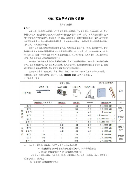
2.产品选型一览表注:(1)常开型防火门根据防火门所在位置及开启要求可选择a:普通机械闭门器++电磁释放器+门磁开关+防火门监控模块的方式;b:防火门闭门器+门磁开关+防火门监控模块的方式;无论何种方式均可将防火门状态通过防火门监控模块上传至防火门监控器,并在火警发生时联动关闭常开型防火门;(2)常闭型防火门根据需要可选择:a:普通型常闭防火门监控模块+门磁开关+机械闭门器方式;b:一体式常闭防火门监控模块+机械闭门器方式;(3)设置常开型防火门时需保证电磁门吸或电动闭门器的供电(耗电量均≤80mA);3.技术参数3.1AFRD100/B防火门监控器3.2防火门区域分机3.3防火门集中电源3.4防火门监控模块4.产品报价4.1AFRD100/B防火门监控器4.2AFRD-QYFJ防火门区域分机4.3AFRD-DY防火门集中电源4.4AFRD-CK/CB/CB(YT)防火门监控模块4.5配套附件。
- 1、下载文档前请自行甄别文档内容的完整性,平台不提供额外的编辑、内容补充、找答案等附加服务。
- 2、"仅部分预览"的文档,不可在线预览部分如存在完整性等问题,可反馈申请退款(可完整预览的文档不适用该条件!)。
- 3、如文档侵犯您的权益,请联系客服反馈,我们会尽快为您处理(人工客服工作时间:9:00-18:30)。
187AFRD系列防火门监控系统安装使用说明书V1.2江苏安科瑞电器制造有限公司Jiangsu Acrel Electric MFG.Co.,Ltd.目录1.AFRD100防火门监控系统简介 (1)1.1.防火门监控系统设计依据 (1)1.2.系统功能简介 (1)1.3.适用场所 (1)1.4.系统组成 (1)2.防火门监控器 (2)2.1.产品概述 (2)2.2.产品特性 (2)2.3.技术参数 (3)2.4.面板元件布置及功能说明 (3)2.5.外形尺寸 (4)2.6.接线 (4)2.7.软件操作画面 (4)2.7.1设备启动与登录 (4)2.8.安装 (10)3.防火门区域分机 (11)3.1.产品概述 (11)3.2.产品特性 (11)3.3.技术参数 (11)3.4.面板元件布置及功能说明 (11)3.5.外形尺寸及接线端子图 (12)3.6.接线 (13)3.7.安装 (13)4.防火门集中电源 (13)4.1.产品概述 (13)4.2.产品特性 (13)4.3.技术参数 (14)4.4.面板元件布置及功能说明 (14)4.5.接线 (15)4.6.安装 (15)5.AFRD系列防火门监控模块 (16)5.1.产品概述 (16)5.2.产品特性 (16)5.3.技术参数 (16)5.4.面板元件布置及功能说明 (16)5.5.外形尺寸 (17)5.6.接线 (18)5.7.安装 (19)5.7.1一体式监控模块 (19)6.AFRD-MC门磁开关 (20)6.1.产品概述 (20)6.2.产品特性 (20)6.3.使用环境 (20)6.4.外形尺寸 (21)6.5.安装 (21)7.AFRD-BMQ电动闭门器 (21)7.1.产品概述 (21)7.2.产品特性 (21)7.3.技术参数 (21)7.4.外形尺寸 (22)7.5.接线 (22)7.6.安装 (22)7.7.操作说明 (23)8.AFRD-DC电磁释放器 (23)8.1.产品概述 (23)8.2.产品特性 (23)8.3.技术参数 (23)8.4.外形尺寸 (24)8.5.接线 (24)8.6.安装 (24)8.7.操作说明 (25)9.注意事项 (25)9.1.施工 (25)9.2.调试 (25)1.AFRD100防火门监控系统简介AFRD100防火门监控系统,是根据国家现行规范标准由安科瑞电气股份有限公司研发的全数字化独立运行的系统,已通过国家消防电子产品质量监督检验中心的试验认证,并取得相关产品合格报告,现均已批量生产并在全国得到广泛的应用。
AFRD100防火门监控系统集工业计算机技术、通讯、抗电磁干扰、数字传感器技术和工业现场总线控制技术于一体的智能化系统,通过对电动闭门器、电磁释放器、门磁开关等进行信号采集及控制,实现防火门工作状态的24小时实时自动巡检,对处于非正常状态的防火门给出故障报警提示。
在发生火情时,发出指令自动关闭常开防火门,隔离火源和烟雾,为火灾救援和人员疏散赢得宝贵时间。
该系统由AFRD100/B型防火门监控器、AFRD型防火门监控模块、AFRD-BMQ电动闭门器、AFRD-DC电磁释放器和AFRD-MC门磁开关等构成。
1.1.防火门监控系统设计依据中华人民共和国国家标准GB29364-2012《防火门监控器》中华人民共和国国家标准GB50116-2013《火灾自动报警系统设计规范》中华人民共和国国家标准GB50016-2014《建筑设计防火规范》中华人民共和国公共安全行业标准GA93-2004《防火门闭门器》1.2.系统功能简介1.2.1.总线控制功能本系统采用消防二总线将具有通信功能的监控模块相互连接起来,当监控系统设备发生短路、断路等故障时,防火门监控器能发出故障报警信号,指示故障报警部位并保存故障报警信息。
1.2.2.消防联动功能本系统可与火灾自动报警系统联动,当发生火情时,可接收火灾报警系统发出的信号,并通过总线,将指令发布到每个终端,自动关闭所有常开防火门,隔离火源和烟雾。
1.2.3.控制输出功能当接收到火灾自动报警系统的信息时,控制输出继电器闭合,当报警消除后,控制输出继电器释放。
1.2.4.远程监控功能当监控距离较远时,可采用区域分机延长通讯距离和供电距离,并将监控信息上传至监控器,监控器可对区域分机下监控模块进行远程监控和复位。
1.2.5.易操作、易维护操作页面采用图形化的显示方式,直观地展现了各通道防火门的工作状态,操作界面简单、方便,软件运行稳定可靠,具有良好的扩展性和可维护性。
1.3.适用场所产品广泛应用于机场、轨道交通、隧道、客运枢纽、医院、学校、体育馆、展览馆、星级酒店、高端商业楼盘等场所。
1.4.系统组成图1系统组成图2.防火门监控器2.1.产品概述AFRD100/B型防火门监控器(以下简称“监控器”)是AFRD100型防火门监控系统的核心,监控器通过二总线与多个防火门监控模块相连,构成集散式防火门监控系统。
监控器能实时接收处理各路监控设备发送的断路、短路、故障信号,同时在液晶屏幕上显示,当断路、短路及通讯故障发生时,监控器能发出声光故障信号,在屏幕上显示故障位置及故障类型,并具有数据存储、查询和报警信号控制输出等功能,还具备对监控模块的远程复位功能。
本设备符合国家标准GB29364-2012《防火门监控器》设计要求。
2.2.产品特性2.2.1.联动控制功能发生火灾时,监控器能接收火灾自动报警系统的信息,自动启动,同时监控器红色“启动”指示灯点亮,关闭所有常开防火门,有效隔离火源和烟雾。
2.2.2.故障报警功能通讯故障报警:当监控器与所接的任一系统设备之间发生通讯故障时或设备自身发生短路、断路故障时,监控画面中相应的被监控终端显示故障提示,同时设备上的黄色“故障”指示灯亮,并发出故障报警声音。
电源故障报警:当主电源或备用电源发生故障时,监控器会发出声光故障信号并显示故障信息,可进入相应的界面查看详细信息并可手动解除故障声响。
2.2.3.自检功能监控器自行检查所有状态指示灯、显示屏、喇叭、打印机是否正常。
2.2.4.记录存储与查询功能当监控器监控到报警或故障等事件时,监控器能自动记录事件类型、事件发生时间、事件发生区域以及事件的详细信息,能存储事件记录超过10000条。
监控器还能提供记录查询功能,可根据需要,自定义查询日期。
2.2.5.电源功能紧急状态下,当主电源发生断电、欠压等故障时,监控器可自动切换到备用电源工作,当主电源恢复正常供电时,自动切回到主电源,切换过程中监控器保持连续平稳运行。
2.2.6.权限控制功能为确保监控系统的安全运行,监控器软件操作权限分为三级,不同级别的操作员具有不同的操作权限。
日常用户级:实时状态监视及操作、事件记录查询、监控模块远程复位;监控操作级:实时状态监视及操作、事件记录查询、监控模块远程复位、设备自检;系统管理级:实时状态监视、事件记录查询、监控模块远程复位、设备自检、监控器系统参数查询、系统维护等。
2.3.技术参数表1参数型号AFRD100/B 输入电源AC220V ±15%50Hz输入功率250W 输出电压DC24V 输出电流10A 最大容量二总线回路容量2*200=400点CAN 总线回路容量可配置32个区域分机总线通讯方式CAN 总线、二总线电源线NH-BV-3×2.5mm ²通讯线ZR-RVSP-2×2.5mm ²通讯距离≤500m (可延长)显示功能8寸触摸平板电脑,全中文及图形显示报警方式声光报警事件记录存储≥10000条打印功能微型热敏打印机操作分级设置3个操作级别,适用于不同级别的工作人员安全操作备电容量阀控密封式铅酸蓄电池,容量12V/12Ah ,2节外形尺寸550*450*200(H*W*D )mm 环境温度-10℃~+55℃相对湿度≤95%RH 海拔高度<2500m 防护等级IP30安装方式壁挂2.4.面板元件布置及功能说明图21:电源指示灯(绿色),当电源正常供电时指示灯常亮,电源发生故障时指示灯闪亮2:门开指示灯(绿色),当被监控的常开防火门全部处于正常打开状态时指示灯常亮3:门关指示灯(绿色),当被监控的常闭防火门全部处于正常关闭状态时指示灯常亮4:故障指示灯(黄色),当监控器接收到故障信号时指示灯点亮5:启动指示灯(红色),当监控器发送给终端动作指令时指示灯点亮,当所有常开防火门执行关闭动作后,指示灯常亮,否则,指示灯闪亮6:消音按钮(黑色),消除报警声音2.5.外形尺寸AFRD100/B型防火门监控器的外形尺寸为:550*450*200(H*W*D)mm.图3AFRD100/B型防火门监控器外形尺寸2.6.接线按照系统施工规范安装监控器和敷设通讯线缆,将通讯线缆接入监控器的通讯总线接线端子。
监控器的接线端子排装于设备的内部,端子排各端子的定义如表2所示。
表2监控器接线端子功能对照表端子序号说明端子序号说明124V电源输出+8CAN总线接线端子2H224V电源输出-9CAN总线接线端子1L3二总线接线端子BUS2+10CAN总线接线端子1H4二总线接线端子BUS2-11联动输入信号正极5二总线接线端子BUS1+12联动输入信号负极6二总线接线端子BUS1-13控制输出端正极7CAN总线接线端子2L14控制输出端负极备注:1通讯总线接线端子为外接通讯总线接线端子;2外接通讯总线须采用屏蔽双绞线;3控制输出为1组常开无源触点,容量:AC220V3A或DC30V3A;4联动信号为有源信号,输入电压为DC24V。
注意:5设备的保护接地端子要妥善接地;6为保证通讯质量,敷设二总线通讯线缆时,建议采用规格为ZR-RVSP-2×2.5mm²的线缆。
敷设CAN总线通讯线缆时,建议采用规格为ZR-RVSP-2×1.5mm²的线缆。
2.7.软件操作画面2.7.1设备启动与登录设备上电后,主机自动运行程序,显示屏显示程序未登录状态下的主页面,如图4所示,此时软件已经准备就绪,等待用户登录。
图4系统未登录界面上方线框内的部分是程序的标题,包含公司名称、产品名称、时间和当前用户。
左下方线框内的部分是功能列表,对应于程序的各个不同功能。
当前只看到一个功能选项,用户登陆后会根据用户权限显示更多功能选项。
右下角占据程序绝大部分界面空间的线框内是各功能页面的内容。
当用户在功能列表选择某一个功能选项时,各页面的内容就会显示到该区域。
当用户点击“登陆”按钮时,程序显示身份确认对话框,用户需要输入4位密码进行登录,各级操作人员的初始密码均为“0000”,如下图5所示:图5系统登录界面登录成功后,“登陆”按钮变成“注销”按钮,此时可使用程序的功能列表,进入不同页面。