翻译 Design of an FPGA Based Controller for Delta Modulated Single-Phase Matrix Converters
基于FPGA的星载NANDFLASH控制器的设计

Abstract: In order to achieve efficient data storage in orbit satellite,this paper designs a NAND FLASH controller based on FPGA. The controller is compatible with commonly used asynchronous NAND FLASH,support for multiple NAND FLASH array ;support NAND FLASH operation timeout anomaly detection;support FLASH reset,read data,program,block erase,read ID and other commonly used functions. Select AHB bus,an efficient on- chip bus proposed by ARM Company. Design the AHB interface module and mount the FPGA module to the AHB bus. Through the Cortex-M3,transfer related commands and data to the underlying FPGA and achieve CPU + FPGA architecture. By simulation and board debugging,the design performance is stable,reducing power consumption,reaching the data storage rate of millisecond requirements. Key words: NAND FLASH;controller;AHB BUS;FPGA
FPGA方面的英文翻译

MCU modern electronic systems consisting of electronic systems will become mainstreamMCU is a device-level computer systems, it can be embedded into any object system to achieve intelligent control. Small to micro-machinery, such as watches, hearing aids. Low-cost integrated device-level, low-to a few dollars, ten dollars, enough to spread to many civilian SCM appliances, electronic toys to go. SCM constitutes a modern electronic systems has in-depth to the households, are changing our lives, such as home audio, televisions, washing machines, microwave ovens, telephones, security systems, and air conditioners. SCM innovation the original electronic systems, such as microwave ovens use SCM, it can easily set the clock, the program memory, power control; air conditioner after use of SCM is not only convenient for remote parameter setting, running automatically transform, frequency control can be achieved. At present, many household appliances such as VCD, DVD only single chip to achieve its function may occur before.Embedded Systems led the entire electronics industry Current electronic components industry, in addition to microprocessors, embedded system devices, the most modern electronic systems around the supporting components industries, such as keys used to meet the human-computer interaction, LED / LCD display drivers, LED / LCD display units, voice integrated device, etc., to meet the requirements of data acquisition channel digital sensor, ADC, data acquisition module, signal conditioning modules to meet the servo drive control in the DAC, solid state relays, stepper motor controller, frequency control unit, etc., to meet the communication requirements various bus driver, level converters.Electronic components in the embedded systems world, driven by embedded applications along fully meet requirements of modern electronic systems development. This makes the original classic world of increasingly small electronic systems. Practitioners in the various electronic systems to modern electronic systems as early as possible to stay.SCM will create a new generation of electronic elite If the 50's, radio has created several generations of the world elite, then today's SCM will create a new generation of e-world elite.A single chip with you to the intelligent electronicsIf we as a dead classic electronic system electronic system, then the intelligent modern electronic systems is a "life" of the electronic system. Application System of hardware, electronic systems, "body", microcontroller applications, the application gives it "life." For example, in the design of intelligent machines monitor display, it can boot the system self-test results show, not to enter the work shows a variety of stand-by state, equipment run-time display running processes, work can be displayed after the end of the current results, self results, raw data, reports and other various processing. Unattended, it can run automatically given a variety of functions.Intelligent electronic systems for the endless realm, often without additional hardware resources can achieve all kinds of renovated function. It is also present in many household appliances feature a large number of additional factors.single chip computer with you to the industrial areaThe 21st century is the century of humanity into the computer age, many people are not used in the manufacture of computer is the computer. People using the computer, only the people engaged in embedded system applications really into the internal computer system hardware and software systems, can we truly understand the nature of the computer's intelligence and grasp the knowledge of intelligent design. MCU applications starting from the learning technology applications in today's computer software training, hardware and technical personnel of one of the best roads. SCM bring you into the most attractive in the digital worldCharming single chip to enable you to experience the true meaning of the computer, you can design intelligent microcontroller hands-on toys, different applications can be designed to achieve different functions. Both software design and hardware making there, both mental and physical, but also hands. Primary level can develop intelligent toys, with macro programming. Intermediate levels can develop some intelligent controller, such as computer mouse, smart cars, all kinds of remote control model. High levels can be developed robots, such as robot soccer, the development of industrial control units, network communications, and high-level language with assembly language or design application. Microcontroller and embedded systems around the formation of the future of the electronics industry, willprovide a vast world of electronic fans, an even broader than the current wireless world, richer, more durable, more attractive in the digital world. Plunge into the microcontroller in the world to, will benefit your life.MCU AttacksCurrently, there are four single chip attack technique, namely:(1) software attackThe technology is commonly used processor communication interface and use protocol, encryption algorithm or the algorithm of security vulnerabilities to attack. The success of software attack is a typical example of the early ATMEL AT89C MCU attacks. Attacker single chip erase operation of the timing design flaw, erase the encryption used by ourselves locked in place, the next stop on-chip program memory data erase operation, thus bringing into too close a single chip SCM not encrypted, and then use the programmer to read out chip program.(2) electronic detection of attacksThe technology is usually a high time resolution to monitor the processor during normal operation of all power and interface simulation features, and by monitoring the electromagnetic radiation characteristics of it to attack. Because SCM is an active electronic device, when it executes a different command, the corresponding changes in the power consumption accordingly. This through the use of special electronic measuring instruments and mathematical statistical analysis and detection of these changes, you can access key information specific microcontroller.(3) fault generation technologyAbnormal working conditions of the technology used to make the processor errors, and provide additional access to attack. Produce the most widely used means of attack, including the fault of the impact and the clock voltage shock. Low voltage and high voltage protection circuit attack can be used to prohibit the work of processor execution errors or enforcement action. Clock transition may reset the transient protection circuit will not damage the protected information. Power and clock transients transition effects in certain single-processor instruction decoding and execution.(4) probeThis technology is directly exposed to chip connection, and then observe, manipulate, interfere with single chip to achieve the attack purpose. For convenience, these four people will attack techniques are divided into two categories is the intrusion type attack (physical attack), such attack requires destruction of package, then use semiconductor test equipment, microscopes and micro-positioning device, in a special laboratory spend hours or even weeks to complete. All of the micro-probe techniques are invasive type attack. The other three methods are non-invasive type attack, attack the MCU will not be physical damage. In some cases, non-invasive-type attacks are particularly dangerous, but because of non-invasive type attacks can usually be made and the necessary equipment to upgrade, so it is cheap.Most non-invasive type attack requires the attacker have a good knowledge of processors and software knowledge. In contrast, the invasive type of probe do not need too much of the initial attack of knowledge, and usually a set of similar technology available to deal with a wide range of productsMCU general process of invasion-type attackInvasive type of attack is thrown off its first chip package. There are two ways to achieve this goal: the first one is completely dissolved out chip package, exposed metal connections. The second is only removed to the top of the plastic package silicon core. The first method is the need to bind to the test fixture on the chip, using bind Taiwan to operate. The second method requires the attacker in addition to a certain degree of knowledge and necessary skills, but also the wisdom and patience, but operate relatively easy.Above the plastic chips can be opened with a knife, epoxy around the chip can be eroded by concentrated nitric acid. Hot concentrated nitric acid will dissolve out without affecting the chip, chip packaging and connection. This process usually very dry conditions, because the presence of water may erode the aluminum wire connections have been exposed.Then, in ultrasonic cleaning of the pool first chip with acetone to remove residual nitric acid, then washed with water to remove salt and dried. No ultrasound pool, are generally skip this step. This case, the chip surface, a bit dirty, but do not affect the operation of UV effects on the chip. The final step is to find the location ofthe protection fuse and fuse protection under exposure to UV light. General use at least a 100 times magnification microscope, from the programming voltage input pin of the connection tracking in, to find protection fuse. If there is no microscope, the use of different parts of the chip is exposed to ultraviolet light and observe the results under the simple search mode. Operation applied opaque paper cover to protect the program memory chips are not erased by ultraviolet light. Will protect the fuse exposed under UV light 5 to 10 minutes to destroy the protection bit of the protective effect, use a simple programmer can directly read the contents of program memory.The use of the protective layer to protect the MCU EEPROM cell, using ultraviolet light reset protection circuit is not feasible. For this type of MCU, the general use of micro-probe technology to read the memory contents. In the chip package is opened, the chip placed under the microscope can easily find from the memory circuit connected to other parts of the data bus.For some reason, the chip lock-bit programming mode is not locked in the memory of the visit. Advantage of this flaw on the data lines to probe the above data can be read all you want. In programming mode, restart the process of reading and connect probe to the other data can be read online program and data memory, all of the information.There is also a possible means of attack is the use of microscopy and laser cutting machines and other equipment to find the fuse protection to this part of the circuit tracing and linking all the signal lines. Because of the design defects, so long as cut off from other circuit protection fuse to a one signal line, you can ban the entire protection. For some reason, this thread is very far from the other line, so the use of laser cutting machine can cut the wire without affecting the adjacent line. In this way, using a simple programmer can directly read the contents of program memory.Although the most common single chip microcontroller has fuse blown inside the code protection features, but because of general low-end MCU is not positioning the production of safe products, so they often do not provide targeted preventive measures and the low level of security. MCU applications with a broad, large sales volume, commission processing and transfer of technology between firms frequentlyspilled a lot of technical data, making use of loopholes in the design of such chips and test interface manufacturer, and by modifying the invasive type fuse protection bits, etc. means of attack or invasion-type attack to read MCU's internal procedures have become easier.About common single chipSTC microcontrollerSTC's mainly based on the 8051 microcontroller core is a new generation of enhanced MCU, the instruction code is fully compatible with the traditional 8051, 8 to 12 times faster, with ADC, 4 Road, PWM, dual serial ports, a global unique ID, encryption of good, strong anti-interference.PIC Microcontroller:MICROCHIP's products is its prominent feature is a small, low power consumption, reduced instruction set, interference, reliability, strong analog interface, the code of confidentiality is good, most of the chip has its compatible FLASH program memory chips.EMC SCM:ELANproducts in Taiwan, with much of the PIC 8-bit microcontroller compatible, and compatible products, resources, compared to the PIC's more, cheap, there are many series of options, but less interference.ATMEL microcontroller (MCU 51):AMTL company's 8-bit microcontroller with AT89, AT90 two series, AT89 series is the 8-bit Flash microcontroller 8051 is compatible with the static clock mode; AT90 RISC MCU is to enhance the structure, all static methods of work, containing the line can be Flash MCU programming, also known A VR microcontroller.PHLIPIS 51PLC Microcontroller (MCU 51):PHILIPS company's MCU is based on the 80C51 microcontroller core, embedded power-down detection, simulation and on-chip RC oscillator and other functions, which makes 51LPC in highly integrated, low cost, low power design to meet various applications performance requirements.TI company microcontroller (MCU 51):Texas Instruments MSP430 provides the TMS370 and two series of general-purpose microcontroller. TMS370 MCU is the 8-bit CMOS MCU with a variety of storage mode, a variety of external interface mode, suitable for real-time control of complex situations; MSP430 MCU is a low power, high functionality integrated 16-bit low-power microcontroller, especially for applications that require low power consumption occasionsTaiwan single, mostly 8-bit machines, some with PIC 8-bit microcontroller compatible, cheap, the system clock frequency may be more options there PMW ADC internal noise filtering within the vibration. Shortcomings RAM space is too small, better anti-interference.单片机开创了现代电子系统时代单片机是器件级计算机系统,它可以嵌入到任何对象体系中去,实现智能化控制。
fpga英文文献翻译
Field-programmable gate array(现场可编程门阵列)1、History ——历史FPGA业界的可编程只读存储器(PROM)和可编程逻辑器件(PLD)萌芽。
可编程只读存储器(PROM)和可编程逻辑器件(PLD)都可以分批在工厂或在现场(现场可编程)编程,然而,可编程逻辑被硬线连接在逻辑门之间。
在80年代末期,为海军水面作战部提供经费的的史蒂夫·卡斯尔曼提出要开发将实现60万可再编程门计算机实验。
卡斯尔曼是成功的,并且与系统有关的专利是在1992年发行的。
1985年,大卫·W·佩奇和卢文R.彼得森获得专利,一些行业的基本概念和可编程逻辑阵列,门,逻辑块技术公司开始成立。
同年,Xilinx共同创始人,Ross Freeman和Bernard Vonderschmitt发明了第一个商业上可行的现场可编程门阵列——XC2064。
该XC2064可实现可编程门与其它门之间可编程互连,是一个新的技术和市场的开端。
XC2064有一个64位可配置逻辑块(CLB),有两个三输入查找表(LUT)。
20多年后,Ross Freeman 进入全国发明家名人堂,名人堂对他的发明赞誉不绝。
Xilinx继续受到挑战,并从1985年到90年代中期迅速增长,当竞争对手如雨后春笋般成立,削弱了显著的市场份额。
到1993年,Actel大约占市场的18%。
上世纪90年代是FPGA的爆炸性时期,无论是在复杂性和生产量。
在90年代初期,FPGA的电信和网络进行了初步应用。
到这个十年结束时,FPGA行业领袖们以他们的方式进入消费电子,汽车和工业应用。
1997年,一个在苏塞克斯大学工作的研究员阿德里安·汤普森,合并遗传算法技术和FPGA来创建一个声音识别装置,使得FPGA的名气可见一斑。
汤姆逊的算法配置10×10的细胞在Xilinx的FPGA芯片阵列,以两个音区分,利用数字芯片的模拟功能。
基于FPGA的交叉耦合控制器的设计与实现
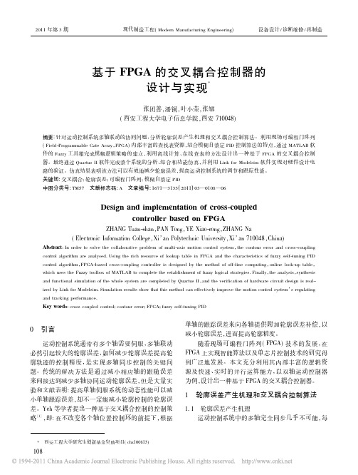
2011年第3期现代制造工程(Modern Manufacturing Engineering)设备设计/诊断维修/再制造基于FPGA的交叉耦合控制器的设计与实现*张团善,潘铜,叶小荣,张娜(西安工程大学电子信息学院,西安710048)摘要:针对运动控制系统多轴联动的协同问题,分析轮廓误差产生机理和交叉耦合控制算法。
利用现场可编程门阵列(Field-Programmable Gate Array,FPGA)内部丰富的查找表资源,结合模糊自整定PID控制算法的特点,通过MATLAB软件的Fuzzy工具箱完成模糊逻辑策略的建立,利用离线计算、在线查表的方法设计出一种基于FPGA的交叉耦合控制器。
最终通过Quartus II软件完成整个系统的分析、综合和功能仿真,并利用Link for Modelsim软件实现对硬件设计电路的验证。
仿真结果表明该方法可以有效地减少轮廓误差,提高运动控制系统的调节和跟踪性能。
关键词:交叉耦合;轮廓误差;可编程门阵列;模糊自整定PID中图分类号:TM57文献标志码:A文章编号:1671—3133(2011)03—0108—06Design and implementation of cross-coupledcontroller based on FPGAZHANG Tuan-shan,PAN Tong,YE Xiao-rong,ZHANG Na(Electronic Information College,Xi’an Polytechnic University,Xi’an710048,China) Abstract:In order to solve the collaborative problem of multi-axis motion control system,the contour error and cross-coupling control algorithm are analysed.Using the rich resource of lookup table in FPGA and the characteristics of fuzzy self-tuning PID control algorithm,FPGA-based cross-coupling controller is designed by the method of off-line computing,online look-up table,which uses the Fuzzy toolbox of MATLAB to complete the establishment of fuzzy logical strategies.Finally,the analysis,synthesis and functional simulation of the whole system are completed by Quartus II,and the verification of hardware circuit design is real-ized by Link for Modelsim.Simulation results show that this method can effectively improve the motion control system’s regulating and tracking performance.Key words:cross coupled control;contour error;FPGA;fuzzy self-tuning PID0引言运动控制系统通常有多个轴需要伺服,多轴联动必然引起较大的轮廓误差,如何减少轮廓误差提高轮廓轨迹的控制精度,是实现多轴同步控制的关键问题。
FPGA-Based Advanced Real Traffic Light Controller System Design

IEEE International Workshop on Intelligent Data Acquisition and Advanced Computing Systems: Technology and Applications 6-8 September 2007, Dortmund, GermanyFPGA-Based Advanced Real Traffic Light Controller System DesignWM El-Medany 1, MR Hussain 21) CE Department, IT College, UOB, 32038 Bahrain wmelmedany@itc.uob.bh, /~mbgedwme/ 2) GEOMATEC, Spatial Information Research, Manama, Bahrain, marwan@.Abstract – Traffic light controller establishes a set of rules and controlled autonomously by sensors [6, 7, and 8]. instructions that drivers, pilots, train engineers, and ship The material of this article is arranged as follows: in captains rely on to avoid collisions and other hazards. Traffic section II, we describe the structure of the four roads that control systems include signs, lights and other devices that communicate specific directions, warnings, or requirements. has been used as an example for the design and the time Traffic light controller (TLC) has been implemented using allocated for each traffic light. Description of the microcontroller, FPGA, and ASIC design. FPGA has many hardware design and VHDL model is the subject of advantages over microcontroller, some of these advantages are; section III. In section IV we explain the state diagram of the speed, number of input/output ports and performance which the design. The simulation of the design and FPGA are all very important in TLC design, at the same time ASIC implementation is studied in section V. Finally we discuss design is more expensive than FPGA. Most of the TLCs implemented on FPGA are simple ones that have been our results in section VI. implemented as examples of FSM. This paper concerned with an II. STRUCTURE OF THE FOUR ROADS THAT ARE GOING TO FPGA design implementation of a low cost 24-hour advanced BE CONTROLLED traffic light controller system that was built as a term project of a VLSI design subject using VHDL. The implemented traffic light Fig. 1 shows the structure of the four roads that has is one of the real and complex traffic lights in Kingdom of been used as a practical example to design our controller Bahrain, for four roads and motorway with sensors and camera. which are located in Manama city, Kingdom of Bahrain. The system has been successfully tested and implemented in In this structure we have six traffics, T1, T2, T3, T4, T5, hardware using Xilinx Spartan 3 FPGA. The system has many and T6. The main roads are T1 and T3. There is also one advantages over the exciting TLC. Keywords - FPGA, Xilinx, VHDL, VLSI.I. INTRODUCTION Field programmable gate arrays (FPGAs) are extensively used in rapid prototyping and verification of a conceptual design and also used in electronic systems when the mask-production of a custom IC becomes prohibitively expensive due to the small quantity [1]. Many system designs that used to be built in custom silicon VLSI [2] are now implemented in Field Programmable Gate Arrays. This is because of the high cost of building a mask production of a custom VLSI especially for small quantity [3]. In this paper the main objective was to design a 24houre traffic light controller to manage the traffic movement of four roads at the same time, and achieve maximum utilization for the four roads. Optimal traffic light control is a multi-agent decision problem, our design learns the expected waiting times of cars for red and green lights at each intersection [4, 5, and 6]. In the rush hours, when people going to work or coming back to home the traffic lights of all roads are controlled with fixed time. However, in the normal time, the main roads are controlled with a fixed time while the narrow roads arecamera which is placed only for traffic T1. The timing for the traffic’s is working as follows: - T1 and T3 are green for 12 seconds. - Other traffics are green for 6 seconds. - The green to yellow sign in each traffic light has 2 seconds delay. - There is 2 second safety during transition from one traffic light to another (or from one road to another). - The red to red yellow sign in each traffic light has 1 second delay. Assuming that the roads are crowded (all sensors equal to logic ‘1’); the normal scenario of the traffic is as follows: - The system starts with T1 and T2 having the green sign. - T1 and T2 will stay green, after six seconds T2 will turn to red and T3 will be green. - After the remaining time for T1 finishes, T1 will turn to red and T4 will be green. - After the time for T3 and T4 finishes, both return to red. Then it is the turn for T5 to be green for six seconds. - Finally T6 will become green after T5 finishes. Table 1 show a timing states for the six traffic lights for the green and red lights only.1-4244-1348-6/07/$25.00 ©2007 IEEE100Bahrain NationalCameraBeat Al-QuranMosqueToT1T2T5To Exhibition T6 T4T3Green AreaDiplomat HotelFig. 1. The Four Roads Structure.What if some of the roads are empty (their sensors are logic ‘0’): There are some procedures to be done before turning from one traffic light to another, and they are as follows: - If the timer of the current traffic finishes and still there are cars on its road , the traffic will not get red unless it makes sure that there is another traffic with sensor = logic ‘1’. - If there is no other traffic having cars, so the current traffic will stay green unless one of the two conditions appears: 1. A car came in other traffic light (sensor will be logic ‘1’). Here the current traffic will changed to red and the other traffic light will be green. 2. If the sensor of the current traffic become logic ‘0’ (means the cars in its road finished) and still other sensors are equal to logic ‘0’; Here the current traffic will be turned to red and T1 and T3 will be green as we assumed they are the two main traffics (main roads). These steps are the conditions that has to be checked before switching between any two traffics for the whole times (24-hours).Important Notes: - When T1 is Green T4, T5 and T6 should be Red (T2 or T3 can be Green at the same time). - When T2 is Green T4, T3, T5 and T6 should be Red (T1 is Green too). - When T3 is Green T2, T5 and T6 should be Red (T1 or T4 can be Green at the same time). - When T4 is Green T1, T2, T5 and T6 should be Red (T3 is Green too). - When T5 is Green all other traffics should be Red. - When T6 is Green all other traffics should be Red.TABLE 1TRAFFIC LIGHT TIMING STATESTime T1 Grn Grn Rd Rd Rd T2 Grn Rd Rd Rd Rd T3 Rd Grn Grn Rd Rd T4 Rd Rd Grn Rd Rd T5 Rd Rd Rd Grn Rd T6 Rd Rd Rd Rd Grn1st 6 sec 2nd 6 sec 3 4 5rd th th6 sec 6 sec 6 secIII.HARDWAR DESIGN AND VHDL MODELTraffic lights can sense and respond to traffic because of a wire loop embedded in the road. Electric current, run through the loop, creates a magnetic field. When a car101bumper interferes with this field, a signal is sent to a roadside traffic light controller. The design of our traffic light system went through three stages. The first stage was the implementation of the state diagram. The second stage is writing and simulating the VHDL code [9], which will be the rules to control the traffic signs. The last stage is programming the FPGA and development of the interface circuit. The system has been successfully implemented, tested and compared to the existing traffic lights in Kingdom of Bahrain. Fig. 2. shows the VHDL model of the controller, where: - Clock: Is the system clock. - Reset: Is the system reset. - S1, S2, S3, S4, S5, S6 and Sc: All are Sensors used to sense if there are any car exists in any road. Sc is used to sense any car break the Red sign in the main road.IV. STATE DIAGRAM Fig. 3. shows the state diagram of the controller which includes 65 states. The transition from state 0 to state 19 depends only on the time delay for each traffic state, which represents the case when all sensors are active; this means that there are cars in all roads. States (s0, s4, s8, s12, and s16) are the main states in which the traffic is either green or red. There are three intermediate states between each two of the main states, these intermediate states represents the Yellow of the active traffic (Green), all red which is the safety state, and Red-Yellow for the next active traffic. When all sensors are active the transition of the main states will follow the sequence of the green light as shown in the state table of figure (2). The sequence of the green light will be (T1&T2, T1&T3, T3&T4, T5, T6, and continue T1&T2 …). That is why we have five states (s0, s4, s8, s12, and s16). The rest of the 65 states used for the transitions in case of some sensors are active and some are not. These states are numbered (SN1-N2-N3) where N1 refer to the present state, N2 refer to the next state, and N3 refer to light output as mentioned in section III. V. SIMULATION AND FPGA IMPLEMENTATION--T1, T2, T3, T4, T5 and T6: All represents the six traffic light that the system is going to control them. For example T1 <2:0> represents the (red, yellow and green) sign, where each colure represents one bit (T1 <2> Green, T1 <1> Yellow and T1 <0> Red). Seven_Seg: Represents the Seven Segment Display for the traffic timing. AN: Represents the four anodes of the Seven Segment Display. Camera: This will be on when Sc and the main road red sign is on (logic ‘1’).Fig. 4. Shows the simulation results for the controller with all sensors are active, in this case it is clear from the simulation that the transition between the main states depends only on the timer of each state, and the transition will be (st0, st1, …, st19), and then starts again from st0. In Fig. 5., only sensor S5 and S6 are active in state st0, in that case the priority is for traffic T5, then T6 which are correspond to st12 and st16 respectively. The simulation results in Fig. 4. and Fig. 5. follow the same sequence of the state diagram in Fig. 3., either from the transition point of view or the output of each state point of view. Fig. 6. shows the RTL schematic of the controller, the total number of logic gates in the design is 62 K. The design has been tested on Spartan 2E FPGA, then has been modified and tested on Spartan 3 FPGA starter kit.Fig. 2. VHDL Model of the Controller.102Fig. 3. State Diagram of the Controller.103Fig. 4. Simulation Results for the Controller With all sensors are active.Fig. 5. Simulation Results for the Controller With sensors S5 & S6 only are active104VI.CONCLUSIONAn FPGA design of A 24-hour traffic light controller system of a four roads structure with six traffic lights has been simulated, implemented and tested. The system has been designed using VHDL, and implemented on hardware using Xilinx Spartan 3 FPGA Starter kit. Our design reaches the maximum utilization of the traffic either during rush hours or normal time. More functions could be added to the design. Some of these functions are to control more than six traffic lights. Also, to allow the user to assign the time for each traffic light (i.e. minimum time to be Green), adding more sensors on each road to count the number of cars in each road and check for the longer queue to increase the timer for that road, another function is to link the traffic light with the other traffic lights along the streets to increase the flow of traffic. ACKNOWLEDGMENT We would like to thank the project team work Mr. Ahmed Abu-Aesh, Mr Mohammed Ahmed Noor, and Mr. Hamza Ahmed who made this work possible. REFERENCES[1] [2] [3] [4] Wayne Wolf, FPGA-Based System Design, Prentice Hall, 2005. Jan M. Rabaey, Digital Integrated Circuits, A Design Perspective, Second Ed., Prentice Hall, 2003. Design of a VLSI Integrated Circuit, IEEE, Piscataway, USA. Taehee Han; Chiho Lin, “Design of an intelligence traffic light controller (ITLC) with VHDL,” Proceedings 2002 IEEE Region 10 Conference on Computers, Communications, Control and Power Engineering (TENCON '02), 28-31 Oct. 2002, vol 3, pp:1749 1752. M. Vreeken, J. van Veenen, J. A. Koopman, “Simulation and optimization of traffic in a city,” IEEE WieringIntelligent Vehicles Symposium, 14-17 June 2004, pp. 453 – 458. Malik J. Ojha, “Design of a VLSI FPGA integrated circuit,” Dept. of Eng., Denver Univ., CO, USA, Technical, Professional and Student Development Workshop, 2005 IEEE Region 5 and IEEE Denver Section, 7-8 April 2005. Yi-Sheng Huang, “Design of traffic light control systems using statecharts,” The Computer Journal, Nov 2006, vol. 49, pp. 634 – 649. Li Lin; Tang N an; Mu Xiangvang; Shi Fubing, “Implementation of traffic lights control based on Petri nets,” Proceedings of IEEE Intelligent Transportation Systems Symposium, 12-15 Oct 2003, vol. 2. Mark Zwolinski, Digital System Design With VHDL, Second Ed., Prentice Hall, 2004.[5][6][7][8][9]Fig. 6. RTL Schematic for the Controller.105。
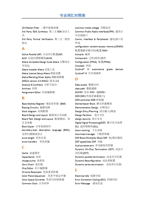
FPGA开发专业词汇对照表
Electrical Idle 电路空闲 Error Correction Coding (ECC) 纠错代码 Error Message 错误信息
专业词汇对照表
Ethernet 以太网 External Memory Interfaces 外部存储器接 口 (IP)
F
Fast Passive Parallel (FPP) 快速被动并行配 置(FPP) Fitter 布局布线器 Filtered Luma Adaptive Algorithm 亮度滤波 自适应算法 Functional Blocks 功能模块
N
Nios II IDE Nios II 集成开发环境
O
offset 偏置/偏移量 On-Chip Debug On-Chip 调试 on-chip memory 片内存储器
P
Pad Placement 垫布局 Parallel Flash Loader 并行 Flash 加载 Parallel Synthesis 并行综合 part per million (ppm) 百万分率 Passive Serial (PS) 被动串行配置(PS) patch 补丁 PCI Express-to-DDR2 reference design PCI
B
Base Address Register 基址寄存器 (BAR) Biasing Circuitry 偏置电路 block diagram 结构框图 Board Design and Layout 板级设计及布板 Board Test, Design and Layout 板级测试,设 计及布板 Boot Copier 引导复制程序 boundary-scan description language (BSDL) 边界扫描描述语言 burst length 突发长度 burst transfers 突发传输
电子信息工程专业英语课文翻译
电子信息工程专业英语教程第三版译者:唐亦林p32In 1945 H. W. Bode presented a system for analyzing the stability of feedback systems by using graphical methods. Until this time, feedback analysis was done by multiplication and division, so calculation of transfer functions was a time consuming and laborious task. Remember, engineers did not have calculators or computers until the '70s. Bode presented a log technique that transformed the intensely mathematical process of calculating a feedback system's stability into graphical analysis that was simple and perceptive. Feedback system design was still complicated, but it no longer was an art dominated by a few electrical engineers kept in a small dark room. Any electrical engineer could use Bode's methods find the stability of a feedback circuit, so the application of feedback to machines began to grow. There really wasn't much call for electronic feedback design until computers and transducers become of age.1945年HW伯德提出了一套系统方法,用图形化方法来分析反馈系统的稳定性。
基于FPGA的CAN设计
a)CAN可以是对等结构,即多主机工作方式,网络上任意一个节点可以在任意时刻主动地向网络上其它节点发送信息,不分主从,通讯方式灵活。
b)CAN网络上的节点可以分为不同的优先级,满足不同的实时需要。
c)CAN采用非破坏性仲裁技术,Байду номын сангаас两个节点同时向网络上传送信息时,优先级低的节点自动停止发送,在网络负载很重的情况下不会出现网络瘫痪。
Keywords: Verilog HDL; FPGA; CANBUS
1绪论
1.1CAN总线简介
控制器局域网CAN(Controller Area Net)是一种现场总线,主要用于各种过程检测及控制。CAN最初是由德国BOSCH公司为汽车监测和控制而设计的,目前CAN已逐步应用到其它工业控制中,现已成为ISO-11898国际标准。
In the thesis, our work is started from the lower level. Firstly, we analyze theCAN Protocol. Secondly, we 'split the entire CAN controller into several moduleswhich are independent but associated with each other. Thirdly, their function andprinciple are introduced. At last, we manage to design the modules in RTL-level, toexplain the idea and process, and to improve design for timing correctly by simulation.The simulation is divided into two parts: One is the logic function simulation, theother is simulation including information of the netlist and gate delay.
- 1、下载文档前请自行甄别文档内容的完整性,平台不提供额外的编辑、内容补充、找答案等附加服务。
- 2、"仅部分预览"的文档,不可在线预览部分如存在完整性等问题,可反馈申请退款(可完整预览的文档不适用该条件!)。
- 3、如文档侵犯您的权益,请联系客服反馈,我们会尽快为您处理(人工客服工作时间:9:00-18:30)。
974 Journal of Power Electronics, Vol. 12, No. 6, November 2012/10.6113/JPE.2012.12.6.974Design of an FPGA Based Controller for DeltaModulated Single-Phase Matrix ConvertersAnshul Agarwal* and Vineeta Agarwal†*Dept. of Electrical Engineering, National Institute of Technology, Hamirpur, Himachal Pradesh, India†Dept. of Electrical Engineering, Motilal Nehru National Institute of Technology, Uttar Pradesh, IndiaAbstractA FPGA based delta modulated single phase matrix converter has been developed that may be used in both cyclo-converters and cyclo-inverters. This converter is ideal for variable speed electrical drives, induction heating, fluorescent lighting, ballasts and high frequency power supplies. The peripheral input-output and FPGA interfacing have been developed through Xilinx 9.2i, to generate delta modulated trigger pulses for the converter. The controller has been relieved of the time consuming computational task of PWM signal generation by implementing the method of trigger pulse generation in a FPGA by using Hardware Description Language VHDL in Xilinx. The trigger circuit has been tested qualitatively by observing various waveforms on an oscilloscope. The operation of the proposed system has been found to be satisfactory.Key words:Cyclo-Converter, Cyclo-Inverter, Field Programmable Gate Array (FPGA), Matrix Converter, Very High Speed Integrated Circuits Hardware Description Language (VHDL)I.I NTRODUCTIONThe operation and maintenance of converters requires the development of expertise and hence costly labor [1]. The use of a matrix converter reduces the need for learning many varying converter topologies which is one of the reasons that this is now the subject of current active research [2]. Fully controlled frequency changers based on cyclo-converter arrangement have a topology that is similar to those of single-phase matrix converters [3]. The matrix converter (MC) is an advanced circuit topology that offers many advantages such as the ability to regenerate energy back to the utility, sinusoidal input and output currents and a controllable input current displacement factor [4]. It has the potential for affording an “all silicon” solution for AC-AC conversion and for removing the need for the reactive energy storage components used in conventional rectifier-inverter based systems [5].This paper proposes a single-phase matrix converter (SPMC) that has been used to perform the functions of a generalized frequency converter capable of operating both as a cyclo-converter and as a cyclo-inverter. A cyclo-converter converts ac input power at one frequency to ac output power at a lower frequency whereas a cyclo-inverter converts ac input power at one frequency to ac output power at a higher frequency. This matrix converter finds application in the speed control of electrical drives, induction heating, fluorescent lighting, ballasts and high frequency power supplies [6], [7]. However, the output of the matrix converter is rich in harmonics [8]. Various modulation techniques employed to improve the quality of the output voltage of matrix converters include sinusoidal PWM [9], space vector PWM [10], [11] and delta modulation [12], [13]. Delta modulation offers a number of advantages such as a simple electronic circuitry without external feedback from a high power circuit, inherent constant volts per hertz control for a preset frequency range, smooth transitions between the constant volt per hertz and the constant volts modes of operation, severe attenuation of the low order harmonics, low communication rates for high modulation signals and guaranteed on/off time for the switches [14]. Microcontroller devices [15] or digital signal processors (DSPs) may be used to implement the delta modulation technique. However, microprocessor-based techniques have the disadvantages of a complex circuitry, limited functions, and difficulty in circuit modification. Digital PWM control with a DSP has the advantages [16] of a simple circuitry, softwareManuscript received Feb. 2, 2011; revised Oct. 18, 2012 Recommended for publication by Associate Editor Tae-Woong Kim.†Corresponding Author: vineeta@mnnit.ac.inTel: +91-9838075072, Fax: +915322540581, MNNIT Allahabad*Dept. of Electrical Engineering, National Institute of Technology, IndiaJournal of Power Electronics, Vol. 12, No. 6, November 2012 975 control, and flexibility in adaptation to various applications.However, generating PWM gating signals and current controlloops requires a high sampling rate to achieve wide bandwidthperformance [17].In recent years, the development of application-specificintegrated circuit (ASIC) technology has made it possible tointegrate complex analog and digital circuits by utilizing thelibraries of basic circuit cells [18]. With the advancement ofvarious technical aspects of ASIC, three major categories havebeen developed: cell based integrated circuits (CBIC), gatearrays, and programmable logic devices (PLD) [19]. Thefield-programmable gate array (FPGA) is a new PLDdeveloped by Xilinx, Inc. [20]. The FPGA comprisesthousands of logic gates, some of which are grouped togetheras a configurable logic block (CLB) to simplify thehigher-level circuit design. The simplicity and programmabilityof the FPGA [21] designate it as the most favorable choice forprototyping an ASIC.When compared with conventional schemes, the advantagesof the FPGA include three aspects. First of all, the FPGA IOresource is abundant [22]. Secondly, the real time control needsfaster digital circuits than before, and the performance of theFPGA to the design sequential logic circuits is good [23].Lastly, the development environment of the FPGA is easy touse. The difficulty and time cost for the hardware design havebeen greatly reduced [24]. With the FPGA implementation ofthe delta modulation process, the information is faster and thecontroller architecture can be optimized for space or speed andit is available in radiation tolerant package [25].II.P RINCIPLE OF O PERATIONFig. 1(a) shows a single phase matrix converter used as ageneralized frequency converter. It consists of fourbi-directional switches capable of blocking voltage andconducting current in both directions. In the absence of a bidirectional switch module, a common emitter anti-parallel IGBT with a diode pair, as shown in Fig. 1(b), is used. The diodes provide reverse blocking capability to the switch module. The IGBT was used due to its high switching capabilities and high current carrying capacities, which are desirable for high-power applications. The output can be obtained through proper conduction of the switches in two input cycles. For example, say for the cyclo-converter operation, if the output frequency is half of the input frequency then in the positive input cycle for positive output, switches S1a and S4a will conduct while for the negative input cycle if the output is positive, switches S3b and S2b will conduct (Fig.2 (a)). The negative half output of the cyclo-converter will be obtained by the conduction of switches S2a and S3a and switches S4b and S1b as shown in Fig. 2 (b). The operation of the cyclo-inverter can be explained in a similar manner. However, the outputs of both the cyclo-inverter and the cyclo-converter are very far from sinusoidal and contain a large number of harmonics. This is reduced by applying the delta modulation technique and implementing it on the FPGA.III.D ELTA M ODULATION T ECHNIQUE Delta modulation, consisting of a forward comparator and a feedback filter, utilizes a sine reference wave V R and a delta shaped carrier wave V F as shown in Fig. 3. The carrier wave V F is allowed to oscillate within a defined window extending equally above and below the reference wave V R.The reference signal V R is compared with a carrier signal V F obtained by integrating the comparator output signal to produce an error signal, e. The error signal, e, is quantized into one of two possible levels ±E depending on its polarity, whereas the slope of the reference signal determines the timeduration Fig. 1. Single phase matrix converter.(a) For positive output.(b) For negative output.Fig. 2. Cyclo-converter operation.976 Journal of Power Electronics, Vol. 12, No. 6, November 2012between two successive levels. The comparator output is regularly sampled by the signal f c to produce the output binary pulses. Fig. 4(a) and 4(b) show the waveforms at various nodes in the modulator block diagram.The closed loop arrangement of the modulator ensures that the integrated output faithfully tracks the reference signal within the upper and lower boundary levels. However, it is important to note that as V R increases in frequency, the component of V o at that frequency also increases in amplitude. Thus the amplitude transfer characteristic of the linear delta modulator demonstrates strong frequency dependence [26], which is often undesirable in power electronic applications where the demodulator, most frequently, is a simple low pass filter. Further examination of the operation of the linear delta modulator shows that in order to ensure that the feedback signal, V F , tracks the reference, a slope overload condition must be satisfied. This requires that dV R / dt should never exceed the maximum rate for the change of V F . Let:sin()w =R s o V V t (1)maxw éù=êúëûR s o dV V dt (2)maxéùêúëûF dV dt= i o K V(3)where ωo is the reference signal radian frequency, K i is theintegrator gain and V o is the output switching level. From (2) and (3):£s o i o V K V w(4)From (4) it follows that a linear delta modulator cannot encode a high frequency sinusoidal signal without running into a slope overload condition, unless the input amplitude is restricted.This interdependence of the amplitude and frequency of the reference signal in the slope overload condition can be eliminated [27] by integrating the reference as shown in Fig. 5. For V F to track V R , the maximum slope of V R ≤ maximum slope of V F . Now:R V = i K òi V dt = sin()òi s o K V t dt w =-()i so oK V Cos t w w(5)Hence, from the slope overload condition:£s c V V(6)The slope overload condition is now independent of thereference frequency and the amplitude transfer gain is seen to be unity, which are very desirable attributes [28]. The same objective can be achieved by replacing the two integrators in Fig. 5 with one integrator placed after the summing junction. This leads to a unity feedback system with the integrator [29] in the forward path as shown in Fig. 6.Fig. 5.Delta modulator with integrator at input.Fig. 6.Block diagram of sigma delta modulator.Fig. 3. Block diagram of delta modulator.Fig. 4. Delta modulation technique. (a) Reference signal and carrier signal. (b) Delta modulated switching functions.Journal of Power Electronics, Vol. 12, No. 6, November 2012 977Fig. 7. Block diagram to generate the triggering pulses.The integrator position results in substantially zero steadystate error for any reference with a frequency that is muchsmaller than the sampling frequency, f c. This delta modulationscheme is popularly known as sigma delta modulation [30].For a single phase cyclo-inverter a sine wave having thedesired output frequency, is the input to the modulator.IV.T RIGGER P ULSE G ENERATION ON A FPGAFig. 7 shows a block diagram to generate the deltamodulated trigger signals for the proposed matrix converter.First, three basic signals X1 (at 50 Hz), X2 (at 50 × N r Hz) andX3 (at 50/N r Hz) are generated in the pulse generator block.Trigger signals are then generated in the logical operator blockwith the help of these basic signals. In the delta modulatorblock the delta modulated signal is generated by comparing atriangular carrier wave with the delta modulated sine referencewave. The output of the delta modulator block and the logicaloperator block are multiplied in the multiplier block and fed tothe gates the IGBTs of the matrix converter through theisolation and driver circuits. A detail description of each blockis illustrated in the following subsections.A. Basic Signal GenerationIn order to generate the basic signals on a FPGA, aSpartan-3E FPGA kit is used whose internal main clockfrequency is 50 MHz. To get signal X1 at 50 Hz, from theinput clock of 50 MHz, 500000 clocks are counted and then theoutput pulse is reset. Counting the same number of clocksagain the output wave is set. This gives the desired frequencyoutput. The formula used in the code is:/2=out clkf f N(7)where =outf Desired output frequency pulse.clkf= Main clock of the FPGA.N= No. of clocks to be counted.Fig. 8. Flowchart for 50 Hz signal generation.A flowchart for the generation of the 50 Hz signal is shownin Fig. 8. In this flow chart the flag is taken as a Booleanvariable which is initially one and becomes zero after counting500000 pulses. The signals X2 and X3 at a desired outputfrequency may be generated in a similar manner. Once thesebasic signals are generated, the logical operation is performedon these signals according to Table 1. Thus the required triggersignals for either converter operation are obtained. Fig. 9 showsthe basic signals and the trigger signals for the cyclo-inverteroperation at an output frequency of 250 Hz.B. Carrier Wave GenerationTo generate a triangular carrier waveform, one n-bit counteris used. This counter moves up or down depending on the flagvalue “Temp”. If Temp is set, the counter counts in the upwarddirection; otherwise it counts in the downward direction. In thispaper a 4 bit up/down counter is used that generates an 'M'shape triangular waveform as shown in Fig. 10.The counter value is digitally incremented from 0 to 15 andthen subsequently decremented back to 0 over a period of time.Good accuracy requires high bit number.The frequency of the carrier triangular wave, f c, is related to themain clock frequency by (8):/(21)2=-´nc clkf f(8)where f c is the carrier wave frequencies and n is the bit size ofthe up-down counter. The flow chart shown in Fig. 11illustrates the procedure for the generation of a carrier wave ona FPGA.978 Journal of Power Electronics, Vol. 12, No. 6, November 2012TABLE IL OGICAL E XPRESSION OF T RIGGERING P ULSEF OR T WO CONVERTER O PERATIONFig. 9. Basic signals and trigger signals for cyclo-inverteroperation.Fig. 10.Digitized triangular carrier waveform.Fig. 11. Flowchart for triangular waveform.C. Delta Modulated Signal GenerationA standard delta modulating signal is generated by using thelook-up table technique. Samples of the sinusoidal referencewave are stored at sequential addresses in the ROM in look-uptable form. A binary counter which acts as a memory counterthen addressees the ROM and the sinusoidal samples areupdated by clocking the counter as shown in Fig. 12. Themodulating signals are generated by comparing the scaledsinusoidal signals from the look up table with a triangular wavegenerated from the up/down counter within the hysteresis band.Fig. 12. Sine wave value at different memory location.Journal of Power Electronics, Vol. 12, No. 6, November 2012 979 The comparator compares the up/down counter signal whichis a triangular carrier wave with the ROM data output whichgenerates a sinusoidal signal. The comparison is done for everyclock pulse in every counting step for the carrier value as wellas for the ROM data value. This process is continuous andrepeats every 10 ms. In order to have a different modulationindex the data from the look-up table i.e. the maximum valuesstored for the sinusoidal wave are modified. This is achievedsimply by changing the maximum number of steps in thetriangular waveform i.e. by modifying the number of counts inthe up/down counter the modulation index can be changed.The generated delta modulated pulse is then multiplied by the four switching pulses obtained in Fig. 9 to get the required delta modulated trigger signals. These signals are finally fed to the gates of the IGBTs of the matrix converter with the help of connector pins.V.E XPERIMENTAL R ESULTSThe principle of delta modulation is implemented on a FPGA using Xilinx. Fig. 13 shows a photograph of the experimental set-up. It consists of a Spartan-3E FPGA kit and eight IRG4PH40UD IGBTs, with an ultra fast soft recovery diode, a driver circuit and an opto coupler for isolation. A variable resistance-inductance is used as a load. The logical gating signals for a particular value of N r are generated by VHDL programming in Xilinx ISE-9.2i. The resulting coding is then downloaded to the Spartan-3E FPGA kit. The experimental results are shown by interfacing DSO with the Spartan-3E.Fig. 14 shows the signals X1 (50 Hz) and X2 (250 Hz) for the cyclo-inverter operation while Fig. 15 shows the signals X1 (50 Hz) and X3 (10 Hz) for the cyclo-converter operation. The triangular carrier wave at a frequency of 2 kHz is shown in Fig.16. The switching pulses for an output frequency of 250 Hz and 10 Hz at a carrier frequency of 2 kHz are shown in Fig. 17 and Fig. 18, respectively. Fig. 19 shows the output voltage for an output frequency of 250 Hz for the RL load for a carrier frequency of 2 kHz. The output is almost symmetrical about the x axis. Fig. 20 shows the output voltage for an output frequency of 25 Hz at a carrier frequency of 2 kHz. Some spikes are observed in the voltage waveform because of the presence of an inductance in the load. These spikes are more persistent in case of a low frequency as shown in Fig. 20. Thus the output voltage becomes slightly distorted. The converter has been tested in the output frequency range of 1 Hz to 10 kHz but it can work for other frequencies by taking a high bit up/down counter. Fig. 13. Power circuit of experimental setup.Fig. 14. Signal X1 (top trace: 5 V/div, 10 ms/div) at 50 Hz and signal X2 (bottom trace: 2.5 V/div, 10 ms/div) at 250 Hz.Fig. 15. Signal X1at 50 Hz (top trace: 2.5 V/div, 5 ms/div) and signal X3 (bottom trace: 2.5 V/div, 5 ms/div) at 10 Hz.Fig. 16. Triangular wave generation (2.5 V/div, 10 ms/div) at frequency of 2 kHz.980 Journal of Power Electronics, Vol. 12, No. 6, November 2012Fig. 17. Switching pulses (all trace: 2.5 V/div, 10 ms/div) at f o = 250 Hz.Fig. 18. Switching pulses (all trace: 5 V/div, 5 ms/div) at f o= 10 HzFig. 19. Input voltage (upper trace: 100 V/div, 2 ms/div) & output voltage (lower trace: 50 V/div, 2 ms/div) of matrix converter in cyclo-inverter mode at f o = 250 Hz.Fig. 20. Input voltage (upper trace: 50 V/div, 5 ms/div) & output voltage (lower trace: 50 V/div, 5 ms/div) of matrix converter in cyclo-converter mode at f o= 25 Hz.VI.C ONCLUSIONSA novel IGBT based matrix converter has been proposed on the web pack software of Xilinx 9.2i. The delta modulation technique is applied in the converter in order to improve its output. The technique is implemented on a FPGA Spartan-3E kit. Experimental results are shown by interfacing a digital storage oscilloscope with the Spartan-3E. The obtained switching pulses are applied to the power circuit of the matrix converter to obtain the required output voltage waveforms for the cyclo-inverter and cyclo-converter operations. The converter has been tested from 1 Hz to 10 kHz and the operation of the circuit has been found to be satisfactory.R EFERENCES[1]Bin Wu Pontt, J. Rodriguez, S. Bernet, and S. Kouro“Current-source converter and cycloconverter topologiesfor industrial medium-voltage drives,” IEEE Trans. Ind.Electron., Vol. 55, No. 7, pp. 2786-2797, Jul. 2008.[2]R. K. Gupta, K. K Mohapatra, and A. Somani and N.Mohan, “Direct-matrix-converter-based drive for athree-phase open-end-winding ac machine with advancedfeatures,” IEEE Trans. Ind. Electron., Vol. 57, No. 12, pp.4032-4042, Dec. 2010.[3]P. W. Wheeler, J. Rodriguez, J.C. Clare, L. Empringham,and A. Weinstein, “Matrix converters: a technologyreview,” IEEE Trans. Ind. Electron., Vol. 49, No. 2, pp.276-288, Apr. 2002.[4]M. K. Hamzah, Z. Idris, A. Saparon, and M. S. Yunos,“FPGA design of single-phase matrix converter operatingas a frequency changer,” in Proc. PECon, pp. 1124-1129,2008.[5]S. Vazquez, J. I. Leon, L. G. Franquelo, J. J. Padilla, and J.M. Carrasco, “DC-voltage-ratio control strategy formultilevel cascaded converters fed with a single DCsource,” IEEE Trans. Ind. Electron., Vol. 56, No. 7, pp.2513-2521, Jul. 2009.[6]R. Orletti, M. A. Co, D. S. L. Simonetti, and J. L. F. Vieira,“HID lamp electronic ballast with reduced componentnumber,” IEEE Trans. Ind. Electron., Vol. 56, No. 3, pp.718-725, Mar. 2009.[7]V. Agrawal, A. K. Agarwal, and K. Kant, “A study ofsingle phase to three phase cyclo-converter usingPSPICE,” IEEE Trans. Ind. Electron., Vol. 39, No. 2, pp141-148, Apr. 1992.[8] A. Agarwal and V. Agarwal, “Design of delta modulatedgeneralized frequency converter,” IEEE Trans. Ind.Electron., Vol. 57, No. 11, pp. 3924-3729, Nov. 2010. [9] D. Yonggui and X. Keming, “The SPWM inversion modeof suppressing harmonic waves based on geneticalgorithm,” in Proc. ICEMS , pp. 1304-1307, 2001. [10] A. Mehrizi-Sani and S. Filizadeh, “An optimized spacevector modulation sequence for improved harmonicperformance,” IEEE Trans. Ind. Electron., Vol. 56, No. 8,pp. 2894-2903, Aug. 2009.[11]G. Narayanan, V. T. Ranganathan, D. Zhao, H. K.Krishnamurthy, and R. Ayyanar, “Space vector basedhybrid PWM techniques for reduced current ripple,” IEEETrans. Ind. Electron., Vol. 55, No. 4, pp. 1614-1627, Apr.2008.[12]M. A. Rahman, J. E. Quaicoe, and M. A. Choudhury,Journal of Power Electronics, Vol. 12, No. 6, November 2012 981“Performance Analysis of delta PWM inverters,” IEEE Trans. Power Electron., Vol. PE-2, No. 3, pp. 227-233, Jul. 1987. [13] A. Agarwal and V. Agarwal, “Delta modulated cyclo-inverters,” in Proc. INTELEC, pp. 1-6, 2008. [14] Y. M. Chen, Y. C. Chen, and T. F. Wu, “Feed forward Delta Modulation for Power Converters,” IEEE Trans. Ind. Electron., Vol. 57, No. 12, pp. 4126-4136, Dec. 2010.[15] S. R. Bowes and M. J. Mount, “Microprocessor control ofPWM inverters,” IEE Proceedings B Electric PowerApplications , Vol. 128, No. 6, pp. 293-305, Nov. 1981. [16]B. Kedjar and K. Al-Haddad, “DSP-based implementation of an LQR with integral action for a three-phase three-wire shunt active power filter,” IEEE Trans. Ind. Electron., Vol. 56, No. 8, pp. 2821-2828, Aug. 2009. [17] Y.-Y. Tzou, M.-F. Tsai, Y.-F. Lin, and H. Wu, “Dual-DSP fully digital control of an induction motor,” in Proc ISIE , pp. 673-678, 1996. [18]Y.-Y. Tzou and H.-J. Hsu, “FPGA realization of space-vector PWM control IC for three-phase PWM inverters,” IEEE Trans. Power Electron., Vol. 12, No. 6, pp. 953-963, Nov. 1997. [19]N. A. Rahim and Z. Islam, “field programmable gate array-based pulse-width modulation for single phase active power filter,” American Journal of Applied Sciences , Vol. 6, No. 9, pp. 1742-1747, 2009.[20]E. J. Bueno, A. Hernandez,F. J. Rodriguez, C. Giron, R.Mateos, and S. Cobreces, “A DSP-and FPGA-basedindustrial control with high-speed communicationinterfaces for grid converters applied to distributed powergeneration systems,” IEEE Trans. Ind. Electron., Vol. 56,No. 3, pp. 654-669, Mar. 2009.[21]K. Sugahara, S. Oida, and T. Yokoyama, “Highperformance FPGA controller for digital control of powerelectronics applications,” in Proc . IPEMC , pp. 1425-1429,2009.[22]L. Idkhajine, E. Monmasson, M. W. Naouar, A. Prata, andK. Bouallaga, “Fully Integrated FPGA-Based Controllerfor Synchronous Motor Drive,” IEEE Trans. Ind. Electron.,Vol. 56, No. 10, pp. 4006-4017, Oct. 2009.[23]F. J. Azcondo, A. de Castro, and C. Brañas, “Course ondigital electronics oriented to describing systems inVHDL” IEEE Trans. Ind. Electron., Vol. 57, No. 10, pp.3308-3316, Oct. 2010.[24]S. McKeown and R. Woods, “Low power fieldprogrammable gate array implementation of fast digital signal processing algorithms: characterisation andmanipulation of data locality,” IET Computers & DigitalTechniques , Vol. 5, No. 2, pp. 136-144, Mar. 2011.[25]A. Myaing and V. Dinavahi, “FPGA-based real-time emulation of power electronic systems with detailedrepresentation of device characteristics,” IEEE Trans. Ind.Electron., Vol. 58, No. 1, pp. 358-368, Jan. 2011. [26]C. Canudas-de-Wit, F. Gomez-Estern, and F. R Rubio, “Delta-modulation coding redesign for feedback-controlled systems,” IEEE Trans. Ind. Electron., Vol. 56, No. 7, pp. 2684-2696, Jul. 2009.[27] M. H Kheraluwala and D. M. Divan, “Delta modulation strategies for resonant link inverters,” IEEE Trans. Power Electron., Vol. 2, No. 5, pp. 220-228, Apr. 1990.[28]C. F. Christiansen, M. I. Valla, and C. H. Rivetta, “A synchronization technique for static delta PWM inverter,” IEEE Trans. Ind. Electron., Vol. 35, No. 4, pp. 502-507, Nov. 1988.[29]P. D. Ziogas, “The delta modulation technique in staticPWM inverter,” IEEE Trans. Ind. Appl., Vol. IA-17, No. 2, pp.199-204, Mar./Apr. 1981. [30] J. Paramesh and A. von Jouanne, “Use of sigma-delta modulation to control EMI from switch-mode power supplies,” IEEE Trans. Ind. Electron., Vol. 48, No. 1, pp. 111-117, Feb. 2001.Anshul Agarwal was born in Mathura, India, on May 05, 1984. He received his B.Tech. in Electrical and Electronics Engineering, from the Uttar Pradesh Technical University, Lucknow, India, in 2007, and his M.Tech (Gold Medalist) in Power Electronics and ASIC Design from the Motilal Nehru National Institute of Technology (MNNIT), Allahabad, India, in July 2009. He is currently working as Assistant Professor in the Electrical Engineering Department, National Institute of Technology, Hamirpur (NIT Hamirpur), Himachal Pradesh, India. His current research interests include power electronic devices, converters, inverters and AC to AC converters. Vineeta Agrawal received her B.E. and M.E. from Allahabad University, Allahabad, India, in 1980 and 1984, respectively. She joined the Electrical Engineering Department at the Motilal Nehru Regional Engineering College, Allahabad, India, as a Lecturer, in 1982. While teaching there, she obtained her Ph.D. in Power Electronics. At present she is a Professor in the Department of Electrical Engineering at the Motilal Nehru National Institute of Technology (MNNIT), Allahabad, India. She has taught numerous courses on Electrical Engineering and Electronics. Her current research interests include single phase to three-phase conversions and AC drives. She has a number of publications in journals and conferences in her field. She has attended and presented papers at both national and international conferences.。