LE-8108网络访问使用说明
三星i8180详细使用大全
三星i8180详细使用大全!(基本设定,详细指令,操作技巧,上网,WiFi设置等)转载三星i8180采用Windows Mobile 6.5专业版系统。
拥有800MHz主频的处理器,内存配置分别是256MB RAM和512MB ROM,500万像素摄像头,i8180的AMOLED屏幕保证了画面色彩十分艳丽,手机采用Touch Wiz 2.0界面具备一定的3D效果,综合实力夸张一点说可以用强悍形容。
★设置和使用★1)按键基本设定一般设定》功能键》程式按钮》按键1设置为<确定\关闭>,按住按键1设置为工作模式切换,按键2设置为<向左卷动>(便于在输入文字中选择),按住按键2选择CUBE2)结束程序基本设定一般设定》功能键》X按钮》选中其中的项目3)个人标识基本设定一般设定》我的资讯》识别资讯》输入姓名(很多软件都需要本机有用户名才可注册,并且请用英文名字)4)4G PS星历基本设定一般设定》GPS》XTRA》选中启用XTRA伺服器和透过ACTIVESYNC连接到PC时。
在以后设置好GPRS后,就可以点击下面的下载XTRA资料更新星历了5)高级设定系统》客户反映意见》选择不传送系统》错误报表》选择停止系统》区域设定》地区里选择中文(中国)6)自动屏幕明暗设置开始菜单----》设置----》屏幕和灯光----》亮度-----》自动调整(确认)----》完成(系统默认没有选择)经过此设置后在光线强烈的地方,i8180会通过前摄像头左边的光传感器根据外界光线变化自动增亮屏幕的亮度,反之,在光线比较灰暗或一片漆黑的环境下,自动降低屏幕的亮度。
经过实际试验发现光传感器还能管用,多少解决了在阳光下,看不清屏幕的问题,但在阳光强烈的环境下,特别是屏直接对着阳光时,还是看不清屏幕,此时的屏幕亮度已自动调整到最亮。
(这是液晶屏的通病,牵涉到折光材料的限制)实际使用下来,对提升电池的续航能力还是有效的(不要拍砖,因各自的使用环境不同,本人在室内使用比较多些)当接听或拨打电话,手机靠近耳朵时(用手遮住光传感器也行),屏幕会自动关闭,也是利用光传感器来实现的,三星这点做的很人性化。
v880怎样在家里用WIFI接上电信ADSL无线路由上网
v880怎样在家里用WIFI接上电信ADSL无线路由上网简单的很,你那是电信送的无线猫吧?如果是无线猫就好办了我可是自己研究出来的哦我家为电信E9套餐,带宽2M,送无线猫一个,可手机WIFI连接后总是无法上网,经过我几天的努力终于成功,下面就给大家分享,让你们的手机也能连上宽带,再也不用担心流量不够,再也不用忍受那龟速的GPRS,下载达到200kb/s以上。
废话少说马上送上。
首先确定你的猫有没有WLAN功能,很简单看看上面有没有WLAN指示灯就行。
打开IE登陆网址:http://192.168.1.1/cnc.html(注意后面的页面文件名,不然无法登陆哦!)电信的账号:telecomadmin密码:nE7jA%5m网通的账号:bjcnchgw密码:8mCnC@bj在顶部菜单中“网络”选择“宽带设置”:连接名称:选择列表中已有的虚拟通道值,如果没发现本地的随便选取一条。
模式:选择Route然后再选择PPPoe(如果你是要用电脑来拔号的话只要把这个模式改为Bridge后设置上VPI与VCI就可以了)启用PPPoE代理:这个默认不用开启PPPoE路由桥混合模式:这个一般我们建议都是开启VPI(0-255):填写当地的(成都地区VPI:1)(必须填写正确,不然无法上网;其他地区的可以上网查)VCI(32-65535):填写当地的(成都地区VCI:33)(必须填写正确,不然无法上网;其他地区的可以上网查)服务类型:默认选择UBR WithoutPCRNA T:这个必须开启,不然无法共享上网启用Vlan:不启用(这个是Vlan的功能,我们默认都不开启,如果你对此了解可以开启设置)ID:默认留空(这个和上面的vlan配合使用)802.1p:默认留空(无需选择什么)用户名:填写你的宽带账号密码:填写你的宽带密码服务名称:留空或随便填写拔号方式:选择“有流量时自动连接”启用QOS:默认不选择封装模式:选择默认LLC服务模式:选择INTERNET绑定端口:全部留空不选最后点击保存,重启,OK。
8100 系列网络视频服务器 快速使用指南
8100系列网络视频服务器快速使用指南8100系 列 网 络 视 频 服 务 器 (Network Video Server)快 速 使 用 指 南 (版本 3.0)第 1 页共 51 页8100系列网络视频服务器快速使用指南注 明:非常感谢您购买我公司的产品,如果您有什么疑问或需要请随时联系我们。
本手册可能包含技术上不准确的地方、或与产品功能及操作不相符的地方、或印刷错误。
本手册的内容将根据产品功能的增强而更新,并将定期改进或更新。
本手册中描述的产品,更新的内容将会在本手册的新版本中加入,恕不另行通知。
第 2 页共 51 页8100系列网络视频服务器快速使用指南目 录第一章:产品简介 (4)1.1 主要功能及特点 (4)1.2 主要应用 (6)第二章 安装 (7)2.1 注意事项 (7)2.2 外观及接口说明 (8)2.3 硬件安装 (14)2.3.1 硬盘安装 (14)2.3.2 网络拓扑图 (16)2.3.3 报警输出连接说明 (17)2.4客户端软件的安装 (17)第三章 参数配置 (23)3.1 通过 IE 浏览器进行参数配置 (24)3.2 通过客户端软件进行参数配置 (27)第四章 广域网接入 (33)4.1 使用 PPPoE 接入 (33)4.2 广域网访问 (36)第五章 常见问题解答 (45)附录 出厂默认参数表 (50)第 3 页共 51 页8100系列网络视频服务器快速使用指南第一章:产品简介存储型网络视频服务器采用功能强大的海思3511芯片,结合高性能的操作系统和音视频压缩算法,使得图像传输的流畅度和清晰度达到更高的境界;同时支持双码流,多种接口可以支持强大的扩展功能,满足您更高要求;它内置WEB服务器,可以增强传统监视系统的性能,并为在一个安全的局域网或互联网上发布监控图像提供网络连通性。
网络视频服务器的管理、配置和监控等功能都很容易通过浏览器(Internet Explore)来完成,操作简单方便。
RocketLinx ES8108 产品说明书
RocketLinx ES8108 RocketLinx ES8108F-S RocketLinx ES8108F-M Industrial Ethernet SwitchUser GuideCopyright NoticeComtrol and RocketLinx are trademarks of Comtrol Corporation.Other product names mentioned herein may be trademarks and/or registered trademarks of their respective owners. Second Edition, July 25, 2011Copyright © 2009 - 2011. Comtrol Corporation.All Rights Reserved.Comtrol Corporation makes no representations or warranties with regard to the contents of this document or to the suitability of the Comtrol product for any particular purpose. Specifications are subject to change without notice. Some software or features may not be available at the time of publication. Contact your reseller for current product information.Federal Communications Commission (FCC) StatementThis equipment has been tested and found to comply with the limits for a Class A digital device, pursuant to Part 15 of the FCC Rules. These limits are designed to provide reasonable protection against harmful interference when the equipment is operated in a commercial environment. This equipment generates, uses, and can radiate radio frequency energy and, if not installed and used in accordance with the instruction manual, may cause harmful interference to radio communications. Operation of this equipment in a residential area is likely to cause harmful interference in which case the user will be required to correct the interference at his expense.The user is cautioned that changes and modifications made to the equipment without approval of the manufacturer could void the user's authority to operate this equipment.Document Number: 2000514 Revision BTable of Contents Introduction (5)Product Overview (5)Features (5)Hardware Description (5)Dimensions (6)Front Panel (7)Bottom View (7)LED Indicators (8)Packet Forwarding Ability (8)Broadcast Control (8)Quality of Service (8)IEEE 802.1Q tag based CoS (9)IEEE 802.1Q Type of Service for IPv4 /IPv6 packet (9)Hardware Installation (11)Connecting the Power and Ground (11)Wiring the Relay Output (12)Enabling the Event Alarm (12)Mounting the RocketLinx ES8108/ES8108F (13)Connecting the Ethernet Ports (13)Connecting the Fiber Port (RocketLinx ES8108F) (14)Troubleshooting and Technical Support (17)Troubleshooting (17)Comtrol Support (17)Index (19)Table of ContentsIntroductionProduct OverviewThe RocketLinx ES8108/ES8108F is an 8-port Fast Ethernet switch that is equipped with a 2.0 Gbps Packet Switch engine designed to optimize packet forwarding and filtering to fulfill the needs of industrial communications applications. It provides packet forwarding ability to handle 64 to 1552 packet sizes in 2 priority queues that complies with Quality of Service (QOS) for the best data forwarding performance.In addition, for the best network performance both broadcast storm filtering and flow control functions ensure data delivery without traffic congestion. To avoid interference as well as to extend your network coverage, RocketLinx ES8108F provides two models, which features two 100Mbps fiber ports with either Multi-Mode 2KM or Single-Mode 30KM transceivers to achieve stable long distance transmissions.To perform in hazardous environments, the ES8108/ES8108F switches are equipped with two redundant power inputs, as well as a wide input voltage range to minimize power interruption. The switches also support a wide temperature operating range of -25°C through 70°C. For easy maintenance, ES8108/ES8108F has one alarm relay for the port link event and the power event to provide an alarm useful for service engineers. With their combination of industrial features, the RocketLinx ES8108/ES8108F switches deliver superior, reliable performance even in the most demanding environments.RocketLinx ES8108/ES8108F requires no user setup and immediately starts operating as soon as you power it up. FeaturesThe RocketLinx ES8108/ES8108F family has the following features:•RocketLinx ES8108 has eight 10/100BASE-TX ports•RocketLinx ES8108F has six 10/100BASE-TX ports and two 100BASE-FX (Multi-Mode or Single-Mode) ports •Compact size with full power redundancy•Supports Store-and-Forward switching architecture•QoS for packet forwarding precedence•Broadcast storm packet filtering•Port and power event alarm•IP31 aluminum alloy enclosure•DIN rail or wall mount•Dual power input 12 to 48VDC•Compliance with IEEE Hi-Pot Testing•Operating temperature -25° to 70°CHardware DescriptionThis subsection discusses the following information:•Dimensions on Page 6•Front Panel on Page 7•Bottom View on Page 7•LED Indicators on Page 8IntroductionDimensionsThe RocketLinx ES8108/ES8108F dimensions are 149 mm (H) x 66 mm (W) x 99 mm (D).Introduction Front PanelThe RocketLinx ES8108/ES8108F front panels are illustrated below.Bottom ViewThe bottom view of the RocketLinx ES8108/ES8108Fconsists of one 6-pin removable terminal block connector for two DC power inputs and an event alarm output. There is one 9-pin DIP switch on the bottom for alarm control of port or power event selection.IntroductionLED IndicatorsThere are system diagnostic LEDs and Ethernet Port LEDs located on the front panel of the RocketLinx ES8108/ES8108F. The LED indicators provide administrators with real-time system status. The following table describes the function of each LED indicator Refer to the figure in Front Panel on Page 7 for LED locations.Packet Forwarding AbilityThe RocketLinx ES8108/ES8108F features a packet filtering function for broadcast packet control protection and Quality of Service (QoS). Both features can provide higher performance in a crowded network through traffic filtering and prioritization.This subsection will introduce the principles of traffic control and forwarding precedence, including Broadcast control and Quality of Service.Broadcast ControlThe RocketLinx ES8108/ES8108F begins to drop broadcast packets with DA (destination address) equal to FF:FF:FF:FF:FF:FF if the received broadcast packets are more than the threshold – 198 packets/ per second at 100Mbps or 19 packets / per second at 10Mbps link speed.All ports are enabled with this function by default to provide better network performance and prevent congestion caused by the flooding of broadcast packets.Quality of ServiceThe RocketLinx ES8108/ES8108F supports the frame type priority function, where high priority packets will be queued to a high priority queue to share more bandwidth. The ratio of bandwidth of the high priority to the low priority queue is 8:1. After 8 high priority packets are processed, then 1 low priority packet is processed.Both the RocketLinx ES8108 and RocketLinx ES8108F can examine the specific bits of VLAN Tag and TCP/IP TOS of IPv4 and IPv6.LED StatusDescription PWR1Green on Power is on.Off No power is being supplied.PWR2Green on Power is on.Off No power is being supplied.AlmRed on Port link down or power failure event occurred.Off No event.Port 1- 8 (RocketLinx ES8108)Port 1- 6 (RocketLinx ES8108F)Link (Green on) A network device is detected and linked up.Activity (Green blinks)The port is transmitting or receiving packets from the connected device.Speed (Yellow on/ 100Mbps) A network device is detected and link established at 100Mbps.Speed (Yellow off) A network device is detected and link established at 10Mbps.Fiber port #7, #8 (RocketLinx ES8108F)100Mbps Link (Green on)The port is operating in full-duplex mode.100Mbps Activity (Green Blinks)The port is transmitting or receiving packets from the connected device.Introduction IEEE 802.1Q tag based CoSThe RocketLinx ES8108/ES8108F checks the 3 bits of the priority field carried by a VLAN tag and maps it to the corresponding priority. A packet with a priority field ranging from 0 to 3 will be treated as a low priority packet, and will be stored in a low priority queue. A packet with a priority field ranging from 4 to 7 will be treated as a high priority packet, and will be stored in the high priority queue.IEEE 802.1Q Type of Service for IPv4 /IPv6 packetThe RocketLinx ES8108/ES8108F also provides the IP layer CoS (Class of Service) function by recognizing the priority octet and mapping it to the corresponding priority. For an IPv4 packet, it is embedded in the TOS (Type of Service) Octet.IPv4 Frame FormatIntroductionFor an IPv6 data packet, the Traffic Class Octet is used to differentiate the Class of Service. When this function is enabled, the RocketLinx ES8108/ES8108F will automatically recognize the IP version and capture either the TOS field (IPv4) or Traffic Class field (IPv6) and distribute the packet into the High or Low Queue.IPv6 Frame FormatHardware Installation RocketLinx ES8108/ES8108F User Guide : 2000514 Rev. B - 11Hardware InstallationYou can use the following subsections to install the RocketLinx ES8108/ES8108F:•Connecting the Power and Ground •Wiring the Relay Output on Page 12•Enabling the Event Alarm on Page 12•Mounting the RocketLinx ES8108/ES8108F on Page 13•Connecting the Ethernet Ports on Page 13•Connecting the Fiber Port (RocketLinx ES8108F) on Page 14Connecting the Power and GroundUse the following procedure to connect the power and the ground.1.Insert the positive and negative wires (12-24AWG) into V+ and V- contacts.2.Tighten the wire-clamp screws to prevent the wires from coming loose.Note:Power should be disconnected from the power supply before connecting it tothe switch. Otherwise, your screwdriver blade can inadvertently short your terminal connections to the grounded enclosure.•PWR1 and PWR2 support power redundancy and reverse polarity protection. •If both power inputs are connected, the RocketLinx ES8108/ES8108F is powered from the highest connected voltage.•The RocketLinx ES8108/ES8108F will emit an alarm if the ES8108/ES8108F is no longer receiving power.•Positive and negative power system inputs are both accepted but PWR1 and PWR2 must apply the same mode.3.Connect a ground wire between the chassis and earth ground using 12-24AWG wire to ensure that the RocketLinx ES8108/ES8108F is not damaged by noise or electrical shock. a.Loosen the earth ground screw (displayed in the previous illustration).b.Tighten the screw after the earth ground wire is connected.Note:Do not connect to AC line - Neutral .Hardware InstallationWiring the Relay OutputThe RocketLinx ES8108/ES8108F have a built-in alarm-relay for port link and power events notifications. The relay contacts are normally open and remain open when there is no failure event. The relay contacts will close when there is a failure event t o notify.The failure events are selectable and enabled using the DIP switch on the ES8108/ES8108F. The relay contacts of RocketLinx ES8108/ES8108F are rated for a maximum of 1A at 24VDC.Wiring the alarm relay output is the same as wiring power inputs in Connecting the Power and Ground.1.Insert positive and negative wires into V+ and V-.2.Tighten the wire-clamp screws to prevent the wires from coming loose.Enabling the Event AlarmYou can use this subsection to configure and enable the event alarm to alert maintenance engineers once a system event has occurred. The RocketLinx ES8108/ES8108F is equipped with one dry relay output for port link failure or power failure.On the bottom of the ES8108/ES8108F, there is one 9-pin DIP switch for alarm control. If you connect the alarm (Wiring the Relay Output on Page 12) and set the DIP switch of the intended Alarm to ON, the relay output forms a short circuit if an alarm occurs.Use this table to set the DIP switch for the relay output alarm.Pin Status Description1-8OnEnables the port link down alarm for the corresponding port. Off Disables the port link down alarm on the corresponding port.P9On Enables the power failure alarm. Off Disables the power failure alarm.12 - RocketLinx ES8108/ES8108F User Guide: 2000514 Rev. B Wiring the Relay OutputMounting the RocketLinx ES8108/ES8108F RocketLinx ES8108/ES8108F User Guide : 2000514 Rev. B - 13Hardware InstallationMounting the RocketLinx ES8108/ES8108FYou can mount the RocketLinx ES8108/ES8108F on a DIN rail or mounted to the wall. The DIN rail clip is already attached to the RocketLinx ES8108/ES8108F when packaged.Note:The RocketLinx ES8108/ES8108F will disperse heat through the metal case during PoE port operation. TheRocketLinx ES8108/ES8108F should be installed and mounted onto a panel which provides good heat dispersion.You can use this procedure to mount the ES8108/ES8108F on a DIN rail.1.Insert the upper end of DIN rail clip into the back of DIN rail track from its upper side.2.Lightly push the bottom of DIN rail clip into the track.3.Ensure the DIN rail clip is tightly attached on the track.4.To remove the RocketLinx ES8108/ES8108F from the track, reverse the steps above.To mount the ES8108/ES8108F on the wall:1.Snap the DIN rail plate into the track.2.Attach the ES8108/ES8108F to the wall using the mounting screws.Connecting the Ethernet PortsYou can use the following information to connect standard Ethernet cables between the RocketLinx ES8108/ES8108F 10/100BASE-TX Ethernet ports and the network nodes. The Fast Ethernet ports support 10BASE-T and 100BASE-TX, full- or half-duplex modes.All the Fast Ethernet ports automatically detect the signal from the connected devices to negotiate the link speed and duplex mode. Auto MDI/MDIX allows you to connect another switch, hub, or workstation without changing straight-through or crossover cables. Crossover cables cross-connect the transmit lines at each end to the received lines at the opposite end.The Ethernet cables use Pins 1, 2, 3, and 6 of an 8-pin RJ45 connector. The signals of these pins are converted by the automatic MDIX function, as shown in the following table.Connect one side of an Ethernet cable into any switch port and connect the other side to your attached device. The LINK/ACTLED is lit when the cable is correctly connected. Always make sure that the cables between the switches and attached devices (for example, switch, hub, or workstation) are less than 100 meters (328 feet).The wiring cable types and maximum cable length are as follows.•10BASE-T: 2-pair UTP/STP Category 3, 4, 5 cable, EIA/TIA-568 100-ohm (100 meters)•100BASE-TX: 2-pair UTP/STP Category 5 cable, EIA/TIA-568 100-ohm (100 meters)Pin MDIX SignalsMDI Signals1RD+TD+2RD-TD-3TD+RD+6TD-RD-Switch 3 TD+6 TD-1 RD+2 RD- 3 RD+6 RD-1 TD+2 TD-Router or PC Switch 3 TD+6 TD-1 RD+2 RD- 3 TD+6 TD-1 RD+2 RD-Switch Straight-Through Cabling Crossover Cabling14 - RocketLinx ES8108/ES8108F User Guide : 2000514 Rev. B Connecting the Fiber Port (RocketLinx ES8108F)Hardware InstallationConnecting the Fiber Port (RocketLinx ES8108F)Connect the fiber port on the RocketLinx ES8108F to another fiber Ethernet device using the following information.A wrong connection will cause the fiber port not to work properly.The fiber connector is a standard connector or square connector (SC).Note:In the IEEE standard, it suggests the available transmission distance is 2KM for 62.5/125um fiber optical cable in1310nm wave length. Actually, the attenuation of Multi-Mode 62.5/125um optical fiber cable is 1.5dBm/km and the maximum link distance can up to 4 to 5km.Mode Cable Type WavelengthTransmit Power (min.)Transmit Power (max.)Receive Sensitivity (max.)Receive Sensitivity (min.)Min. LaunchPower –Max. Receive Sensitivity Distance (km)Multi 50/125um 62.5/125um1310nm-20dBm -14dBm -31dBm 0dBm 11dBm 2km Note (below)Single8-10/125um 1310nm-15dBm-8dBm-34dBm-8dBm19dBm30kmThis is a Class 1 Laser/LED product.Hardware Installation IEEE organization recommends maximum optical fiber cable distances as defined in the following table.Standard Data Rate(Mbps)Cable TypeIEEE StandardDistance10BASE-FL10850nm, 50/125um or 62.5/125umMulti-Mode optical fiber cable2km 100BASE-FX1001310nm, 50/125um or 62.5/125umMulti-Mode optical fiber cable2km 100BASE-SX100850nm, 50/125um or 62.5/125umMulti-Mode optical fiber cable300m1000BASE-SX1000850nm, 50/125umMulti-mode optical fiber cable850nm, 62.5/125umMulti-Mode optical fiber cable 550m 220m1000BASE-LX10001310nm, 50/125um or 62.5/125umMulti-mode optical fiber cable1310nm, 9/125umSingle-Mode optical fiber cable 550m 5km1000BASE-LH10001550nm,9/125umSingle-Mode optical fiber cable70kmConnecting the Fiber Port (RocketLinx ES8108F)RocketLinx ES8108/ES8108F User Guide: 2000514 Rev. B - 15Hardware Installation16 - RocketLinx ES8108/ES8108F User Guide: 2000514 Rev. B Connecting the Fiber Port (RocketLinx ES8108F)Troubleshooting and Technical SupportTroubleshootingIf you are having problems, you may want to check the following:•Make sure you are using the correct DC power supplies (12 to 48VDC). Do not use power supplies with DC output over 48VDC.•Select Ethernet cables with specifications suitable for your applications to set up your systems.Ethernet cables are categorized into unshielded twisted-pair (UTP) and shielded twisted-pair (STP) cables.Category 3, 4, 5, and 6 Ethernet cables are suitable for systems with 10 Mbps transmission speed.For systems with 100 Mbps transmission speed, Category 5 and 6 Ethernet cables are the only suitable specifications for this environment.You also need to make sure that the distance between any two nodes does not exceed 100 meters (328 feet).•If the Power LEDs go off when the power cord is plugged in, a power failure might have occurred. Check the power output connection to see if there is any error at the power source. If you still cannot solve the problem, contact Comtrol Technical Support for assistance.Comtrol SupportYou can use one of the following methods to contact Comtrol.Contact Method Web Address or Phone NumberSupport /pub/en/supportDownloads ftp:///html/ES8108.htmWeb Site Phone763.494.4100Troubleshooting and Technical Support RocketLinx ES8108/ES8108F User Guide: 2000514 Rev. B - 17Troubleshooting and Technical Support18 - RocketLinx ES8108/ES8108F User Guide: 2000514 Rev. B Comtrol SupportIndexNumerics100BASE-TX 1310BASE-T 13CcablesFast Ethernet 13DDownloads 17EEthernet 13FFast Ethernet portcables 13Hhardware installation 11Iinstallationhardware 11PPhone 17Ssupport 17Ttechnical support 17WWeb Site 17Index RocketLinx ES8108/ES8108F User Guide: 2000514 Rev. B - 19Index20 - RocketLinx ES8108/ES8108F User Guide: 2000514 Rev. B Index。
工业安全路由器 EDR-810 系列说明书
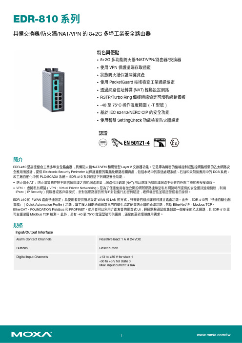
EDR-810系列具備交換器/防火牆/NAT/VPN的8+2G多埠工業安全路由器特色與優點•8+2G多功能防火牆/NAT/VPN/路由器/交換器•使用VPN保護遠端存取通道•狀態防火牆保護關鍵資產•使用PacketGuard技術檢查工業通訊協定•透過網路位址轉譯(NAT)輕鬆設定網路•RSTP/Turbo Ring備援通訊協定可增強網路備援•-40至75°C操作溫度範圍(-T型號)•基於IEC62443/NERC CIP的安全功能•使用智慧SettingCheck功能檢查防火牆設定認證簡介EDR-810是高度整合工業多埠安全路由器,具備防火牆/NAT/VPN和網管型Layer2交換器功能。
它是專為機密的遠端控制或監控網路所需的乙太網路安全應用而設計,提供Electronic Security Perimeter以保護重要的電腦及網路相關資產,包括水站中的泵送處理系統、石油和天然氣應用中的DCS系統、和工廠自動化中的PLC/SCADA系統。
EDR-810系列包括下列網路安全功能:•防火牆/NAT:防火牆策略控制不同信賴區域之間的網路流量,網路位址轉譯(NAT)用以防護內部區域網路不受來自外部主機的未授權連線。
•VPN:虛擬私有網路(VPN;Virtual Private Networking)是為了保護使用者從公開的網際網路連線至私有網路時所提供的安全通訊連線機制,利用IPsec(IP Security)伺服器或客戶端模式,針對該網路層的所有IP封包進行加密與驗證,確保機密性並驗證發送者的身份。
EDR-810的「WAN路由快速設定」為使用者提供簡易設定WAN和LAN的方式,只需要四個步驟即可建立路由功能。
此外,EDR-810的「快速自動化配置檔」(Quick Automation Profile)功能,讓工程人員能透過最常見的自動化協定配置防火牆的過濾功能,包括EtherNet/IP、Modbus TCP、EtherCAT、FOUNDATION Fieldbus和PROFINET。
810系统非可视2线制说明书

跳针 1
2
3
4
5
6
跳针 1
2
3
4
★ 43 层 ★ ★
★
★ 49 层 ★
★ 44 层
★★
★ 50 层
★
★ 45 层 ★
★★
★ 51 层 ★ ★
★ 46 层
★★ ★
★ 52 层
★
★ 47 层 ★ ★ ★ ★
★ 53 层 ★
★
★ 48 层
★ ★ 54 层
★★
5
6
★★
★★
★★
★★
★★
★★
跳针 1 2
3
4
5
6
一层 4 户以上---16 户房间号编码表如下图所示(同时按表 1 和表 2 方式插):
同层第一个解码器 同层第二个解码器 同层第三个解码器 同层第四个解码器
跳针 7
★ ★
跳针 8
★ ★
解码器输出 1
01 05 09 13
解码器输出 2
02 06 10 14
解码器输出 3
03 07 11 15
解码器输出 4
跳针 1
2
3
4
5
6
跳针 1
2
3
4
5
6
55 层 ★ ★ ★
★ ★ 58 层
★
★ ★ ★ 61 层 ★
★★ ★★
56 层
★ ★ ★ 59 层 ★ ★
★ ★ ★ 62 层
★★★ ★★
57 层 ★
★ ★ ★ 60 层
★ ★ ★ ★ 63 层 ★ ★ ★ ★ ★ ★
表1 注:该表是楼层号的设置,打“★”表示该跳针短路(短路即表示插针帽两针插上)
八网口二合一视频控制器使用说明书

KSV8八网口二合一视频控制器版本: v1.0发布日期: 2023年02月使用说明书版本记录版本号变更详情发布时间V1.0 第一次发布2023.02.01安全注意事项危险●设备内有高压,非专业维修人员不得打开后盖,以免发生危险。
警告●本设备非防水设备,在潮湿环境下请做好防水处理;●本设备禁止靠近火源或高温环境;●本设备如发出怪异噪音、冒烟或怪味,应立即拔掉电源插头,并与经销商联系;●严禁带电拔插DP、DVI、HDMI信号线缆。
注意1、使用前请仔细阅读本说明书,并妥善保存以备后用;2、在有雷电或长期不用的情况下,请拔掉电源插头;3、本设备不适合非专业人员操作调试,请在专业人员指导下使用;4、不要从本设备通风孔塞入任何物体,以免造成设备损坏或事故;5、不宜将本设备放置于近水或其它潮湿的地方使用;6、不宜将本设备放置于散热片或其它高温地方使用;7、请妥善整理并放置好电源线,以防破损;8、如存在下列情况,应拔掉本设备电源插头,并委托维修:●有液体溅入本设备时●本设备跌落或机箱损坏时●本设备出现明显功能异常或性能明显变差时声明感谢您使用本公司的产品。
本文档版权属本公司所有,在未征得本公司的书面许可的情况下,严禁以任何形式复制、传递、分发和存储本文档的任何内容。
本公司保留在不预先通知的情况下对本文档中所描述的任何产品功能进行修改和改进的权利,最终解释权归本公司所有。
本产品可能附带有相关的控制软件,该软件仅供您使用,软件的所有权归本公司所有。
您可以进行拷贝,但仅限于个人使用。
若您将此软件用于其它用途,特别是商业用途,请与本公司取得联系。
本公司保留追究侵权行为法律责任的权利。
请您在使用前仔细阅读本手册,操作不当,有可能对产品造成损害;本产品为带电工作产品,请注意用电安全。
若不按照本手册的说明,采取不得当的操作,因而造成的财产损失和人身伤害,本公司不承担责任。
此条如与当地法律法规相抵触之处,以当地法律法规为准。
如果您使用了本产品,意味着您同意以上声明,若您不同意以上声明,则请您与销售方联系,办理相应的退货手续。
必联电子阿里智能无线路由器动态IP上网设置教程XP系统
必联电子阿里智能无线路由器动态IP上网设置教程XP系统在XP系统中设置阿里智能无线路由器动态IP上网需要经过以下步骤:步骤一:连接阿里智能无线路由器1.首先,将电脑与阿里智能无线路由器通过网线连接,确保连接正常。
2. 接下来,打开浏览器,输入阿里智能无线路由器的默认管理地址(通常为192.168.1.1)并按Enter键。
3. 在弹出的登录界面中,输入默认的用户名和密码(通常为admin),点击登录。
步骤二:设置动态IP1.登录成功后,进入路由器的管理界面。
在左侧菜单栏中,选择【网络设置】-【宽带接入】。
2.在宽带接入选项卡中,选择【动态IP】,然后点击【添加】。
3.在弹出的对话框中,选择【自动从DHCP服务器接收IP和DNS地址】选项,然后点击【应用】。
4.设置完成后,系统将自动获取外网的动态IP地址。
步骤三:保存配置并重启路由器1.在配置完成后,将页面滚动到页面底部,点击【保存】,然后点击【重启】。
2.在弹出的对话框中,选择【仅重启路由器】,然后点击【确定】。
3.路由器将会自动重启。
等待重启完成后,你可以继续进行下一步。
步骤四:检查上网状态1.在电脑上,右键点击【网络连接】图标,选择【属性】。
2. 在弹出的对话框中,选择【Internet协议(TCP/IP)】,然后点击【属性】。
3.在弹出的对话框中,选择【自动获取IP地址】和【自动获取DNS 服务器地址】,然后点击【确定】。
4.至此,XP系统中阿里智能无线路由器动态IP上网设置就完成了。
重新启动电脑,连接上无线网络,即可正常上网。
总结:通过以上步骤,你可以在XP系统中成功设置阿里智能无线路由器的动态IP上网。
请确保你的路由器连接正常,并且按照正确的步骤进行设置。
如果仍然无法上网,请检查你的网络连接和配置是否正确。
- 1、下载文档前请自行甄别文档内容的完整性,平台不提供额外的编辑、内容补充、找答案等附加服务。
- 2、"仅部分预览"的文档,不可在线预览部分如存在完整性等问题,可反馈申请退款(可完整预览的文档不适用该条件!)。
- 3、如文档侵犯您的权益,请联系客服反馈,我们会尽快为您处理(人工客服工作时间:9:00-18:30)。
网络访问使用说明
LE-8108数字视频监控系统提供两种网络访问方式供用户使用,即使用客户端软件XNetPlay访问和用IE浏览器直接访问。
而根据网络结构的不同又分为局域网访问和广域网访问。
网络拓扑结构
局域网
如图,在局域网内,客户端计算机(192.168.0.2和192.168.0.3)要访问服务器计算机(192.168.0.1)请使用内网IP地址:192.168.0.1。
广域网
如图,在广域网上,客户端计算机要访问服务器计算机,请使用域名(例如)
前端服务器配置
用户无论使用哪种方式访问哪种网络,都必须首先配置好前端服务器(硬盘录像机)。
用户选择“系统设置->系统参数设置”找到如图所示:
Web站点主目录:指放置网页及控件的全路径,请通过点击[浏览],选择监控系统目录里面的wwwroot文件夹(通常是C:\LE-8108_v3.1\wwwroot)。
默认情况下,系统会自动设置好该主目录,用户再检查一下即可。
Web站点IP地址:如果用户仅在局域网内访问,请填上本机IP地址(即硬盘录像机的IP地址),如果用户还需要在广域网上访问,请填上域名(例如花生壳的动态域名)
广州的用户请注意,根据我们测试,广州宽带是禁止使用80端口的,用户必须修改http端口才能在广域网上正常使用。
(非广州地区可保持默认值80)
用户选择“系统设置->电子地图及网络端口”,找到如上图所示,把Http端口号改为其它值(例如8080)。
网络传输端口号:即图像接收时用到的端口号,如果前端只有一台服务器(硬盘录像机),请保持默认值5050。
路由器配置
用户需要在广域网上访问时,才有必要对路由器进行相关设置。
80:HTTP服务(广州地区请改为其它端口,例如8080,非广州地区可保持默认值80)
5050-5052:图像接收
6789:云台控制
5040:远程配置、状态信息、报警通讯
7050:用户登录校验,远程录像回放
本系统用到的端口号如上所示,下面以D-Link DI-504为例进行说明。
用户选择“进阶设定->虚拟服务器”,添加虚拟服务器
名称:可任意填写,但请根据端口的用途进行命名,有助于日后维护。
个人IP地址:请填上前端服务器(硬盘录像机)的IP地址。
协议模式:保持默认值TCP即可。
私有服务端口,公用服务端口:填上要添加的端口即可,例如这里的8080。
排程:即该端口使用的时间段,通常采用默认值任何时间即可。
最后记得点击[执行]以保存设置。
下图是对150.10.20.123这台服务器配置后的结果:
网络访问
客户端软件XNetPlay2访问
运行程序后,点击“设置->服务器设置->新增”,弹出如下图:
服务器名称:可任意填写,但请根据服务器特点命名,方便日后维护。
通道数:默认值为8,请根据前端服务器(硬盘录像机)的通道数进行填写。
服务器地址:即前端服务器(硬盘录像机)的IP地址。
注意:局域网上访问,请填上内网IP地址(例如:150.10.20.11)。
广域网上访问,请填上域名(例如:)。
端口号:请保持默认值5050,只有前端服务器(硬盘录像机)上的接收端口被更改后,这里才需要作相应更改。
服务器类型:请保持默认值NV系列。
管理员名称、密码:请根据前端服务器(硬盘录像机)现有用户进行填写(例如默认的Admin,Admin或者1,1)。
转发服务器地址:请保持空白。
转发端口:请保持5050。
按[确定],用户即可在“服务器设置”对话框中看到刚才新增的服务器图标,再点击[退出]按钮,退回“通道选择”对话框:
如图,选中“test服务器”,按[],把新增的服务器通道移到右面浏览通道方框,最后按[确认]退出服务器设置。
在程序主界面,点击[连接]按钮,即可接收前端服务器的图像。
如下图:
IE浏览器访问
打开IE浏览器,输入前端服务器(硬盘录像机)的Web站点IP地址(例如:局域网:150.10.20.11,广域网::8080)。
注意:Web站点IP地址请按前面说明先配置好,否则无法连接。
如果Http 端口号修改过(非80),请在域名后面加上端口号(例如:8080)。
如果客户端使用XP系统,请把Internet安全设置中关于ActiveX控件和插件的选项都设为启用或者提示。
第一次访问前端服务器,系统会提示下载一控件
现如下画面:
注意:此处登录的用户名密码是根据前端服务器(硬盘录像机)现有用户输
入的,超级用户Admin不能登录接收图像,用户可在前端服务器(硬盘录像机)添加其它用户进行登录。
如图,登录后,用户在服务器列表双击某一通道即可接收该通道图像。
本控件还提供远程云台控制、远程开关控制(即远程控制报警盒输出)、远程调色和远程回放等到功能。
注意:
前面提及的域名的获取,请参阅<<花生壳使用说明.doc>>。
客户端软件XNetPlay2的详细说明,请参阅<<XNetPlay2远程监控系统使用手册.doc>>。
服务器端软件,请参阅<<LE-8108使用说明.doc>>。