Technicolor CineStyle安装指南安装使用手册
Cineo Lighting Maverick Remote Phosphor灯光源用户指南说明书
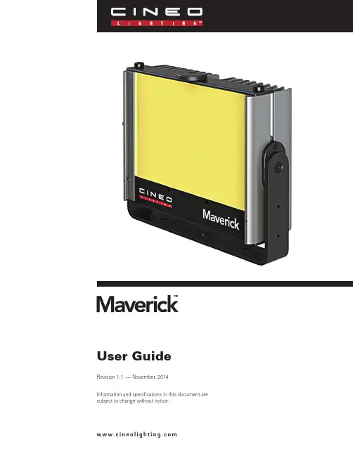
User GuideRevision 1.1 — November, 2014Information and specifications in this document are subject to change without notice.w w w.c in e o l ig h t in g.c o mCineo Lighting has developed the versatile Cineo Maverick Remote Phosphor light source. Maverick operates from many power options, including AC, DC and battery power. The power connection uses an industry-standard XLR4 connector with an input voltage range of 10.8 to 28 VDC. Like all Cineo soft lights, Maverick allows the user to change the Remote Phosphor panels, supporting CCT of 2700K, 3200K, 4300K, 5600K, 6500K, Chroma Blue and Green. Their color quality perfectly matches all other Cineo soft lights, with CRI ratings of 90-98, depending on color temperature. Maverick fixtures feature a versatile mounting system that supports industry-standard hardware for virtually limitless mounting options.Rather than traditional diffusion to soften the light source, the light actually emits from the Remote Phosphor panels on the front of the fixture, providing a light characteristic that radiates equally in a 160º radius, providing Maverick the ability to “wrap” your subject with soft light with edgeless shadows.The phosphor panels are excited by blue LEDs, which are automatically turned off when the phosphor panels are removed. The color temperature of Maverick is extremely consistent fixture to fixture, and will not change over time like other lighting technologies.Cineo Maverick fixtures are extremely durable, built to last with anodized alloy construction, flexible polycarbonate panels, and field-serviceable components. Dimming options include both local and DMX control. Cineo Maverick is perfect for any film or television project, in the studio or on location, or anywhere flicker-free, color-accurate soft light is required.Welcome to Cineo MaverickGeneral Notes1. P lease read through this manual carefully before operating Cineo Maverick, and keep this manual for future reference.2. T here are numerous safety instructions and warnings that must be adhered to for your own safety.3. Maverick is not intended for residential use. It is intended for use in a professional studio.4. Maverick service must be performed by a qualified technician.5. Although Maverick is weather-resistant, the fixture is intended primarily for indoor use.6. Cineo products are not certified for use in hazardous locations.7. Maverick has a typical operating temperature of 120º F (50° C).Fixture Set Up1. Read these safety instructions carefully to ensure fixture and accessories are used safely.2. It is suggested that the fixture is correctly mounted onto the supporting surface before use.3. E nsure the Maverick and power sources are operated within an ambient temperature range of -4 to 122°F (20 to +50°C)System Components, Connections and ControlsMaverick LampheadThe Maverick lamphead represents the next generation of Remote Phosphor professional lighting, incorporating simple operation, advanced passive cooling and versatile configuration options. Local 0-100% dimming is facilitated with a simple rotary control, while adding the DMX module provides remote control of the fixture. Maverick can be configured to run on battery, DC or AC power sources.Maverick typically includes a mounting yoke that can be easily removed from the industry-standard 80/20 profile mounting slot. The 80/20 slot also accommodates additional mounting options from both Cineo Lighting and others.The fixture can be operated in inclement weather conditions, and although not completely waterproof it can withstand moderately wet conditions.Depending on input power and CCT, Maverick can output up to 8,000 lumens from a very compact form factor.Maverick Power SourcesThe Maverick fixture features SmartPower™ power control, allowing operation with any 12-24VDC power source capable of delivering 75 -150 watts. This provides compatibility with a wide range of battery and AC options. Configuration of SmartPower is covered in detail in the Advanced Power Setting section of this guide.Cineo offers the following power accessories for mounting on the either the Maverick yoke or BackPak™ accessory bracket. Maverick can be used with virtually any nominal 12-24VDC power source, including camera batteries, car lighter sockets, etc. Adapters and accessory cables are sold for connection to various power sources, including the following:900.0095 120w portable AC Adapter900.0195 150w studio power supply900.0086 V-Lock Battery Plate900.0094 Gold-Mount Plate903.0003 Maverick Cigar Lighter CableInput power from other sources is also possible, using an XLR4 connector with the following pin configuration:• Pin1 – GND• Pin2 – NC• Pin3 – NC• Pin4 - +VDCAdvanced Power SettingsSmartPower settings are configured on a set of DIP switches located inside the lamphead. By placing these switches inside the fixture, misuse of various power configurations is minimized, as the fixture should be set up with the power sources intended for use in mind.To access the switches, you must remove the lower panel from the lamphead. Two large screws must be removed, plus two smaller screws, as shown in the following photo:The two small switches are located as shown and can be depressed or lifted using a small pin.The simplest way to think about the SmartPower settings is to consider the maximum power capability of your DC source below 18 VDC (Low Voltage setting), and the option of limiting of power draw at a nominal 24VDC (High Voltage setting).Low Voltage setting (LV)A standard capacity V-Lock or Gold Mount camera battery will draw 70-95 watts with an output voltage ranging from 10.5 to 16 VDC. A high-capacity camera battery typically has a 120-150 watt output with a similar output voltage range.If the Maverick is being used with standard capacity batteries, the LV setting should be set to 75 watts; if the fixture will only be used with high-capacity batteries, the LV setting can be set to 120 watts. Note that if the LV setting is 75 watts, virtually any capacity camera battery will work well with Maverick, without damage to the battery.Note the location of the switch labeled “Option A”, which controls the LV setting. When depressed, the LV mode is set to 75 watts. This is indicated on the back of the fixture by illuminating the Red LED. This is the default setting when the fixture is shipped from the factory. When in the UP position, the LV mode is set to 120 watts and the Red LED on the back of the fixture is OFF.Use of the 120 watt LV setting should ONLYbe used with batteries whose output equals orexceeds 120 watts. A standard capacity batterywill exhibit very little run time and risk batterydamage if operating a Maverick with the LVsetting at 120 watts.High Voltage setting (HV)The Maverick fi xture is designed for use with a 24VDC AC adapter when used on house power. The HV switch allows the fi xture to be confi gured for use at 120 watts or up to 135 watts, depending on the application.For portable use, Cineo provides a small, lightweight AC adapter, capable of operating from 90-240 VAC, with a 24VDC output of 120 watts. The mounting bracket for this AC adapter is designed for quick removal of the adapter from the fi xture when minimum weight is a factor.Note the location of switch closest to the bottom of the fi xture, which controls the HV setting (labeled “Option B”). To set the fi xture for 120 watt operation at 24 VDC, the switch position should be DOWN. The Yellow LED on the back of the fi xture will illuminate, indicating the 120 watt mode is selected. This is the default mode when the fi xture is shipped from the factory. When the position of this switch isUP, the fi xture is running at 135 watts. In this mode the fi xture MUST be powered with a 150 watt or greater power source or damage to the power source may occur.Local and Remote DimmingWhen correct DC power is applied to the unit, the green LED illuminates on the back, between the cooling fi ns. The output of the Maverick is controlled with the local control knob on the back of the fi xture. The fi xture does not employ an on/off switch; when the knob position is at 0, the fi xture is virtually off, as it draws only 10 ma of power. The dimming curve is logarithmic in nature, providing a very “analog” characteristic to its control.Remote Dimming via DMXCineo offers a DMX interface module for control of the fi xture via standard DMX lighting protocol. The interface module (900.0087) attaches to either the yoke or the BackPak accessory and connects to the Maverick fi xture’s AUX port via an included RJ45 cable. The module includes both DMX IN and DMX THRU via standard5-pin XLR connections. The DMX pin-out wiring is as follows:• Pin 1: Signal Common• Pin 2: Data -• Pin 3: Data +• Pin 4: Spare• Pin 5: SpareThe DMX control line is automatically self-terminating anddoes not require external DMX termination when no cable isinserted into the DMX THRU connector.Note that when the DMX control is in use and DMX controlsignal is lost, the fi xture will hold its last level. When theMaverick loses power, it retains all of its DMX settings when power is resumed.DMX Module OperationWhen the DMX module is connected to the Maverick fixture, control of the fixture is automatically switched to the module. The DMX module has a multi-line display screen that indicates the firmware level, control mode (local / remote) and DMX address. The module is programmed by the use of four capacitive-touch buttons below the screen (-, +, Mode, Save).There are two control modes: one for determining local or DMX control, and one for setting the DMX address (0 – 255). Touching the Mode button toggles the arrow on the right of the screen between these modes.When the arrow is pointing to the “Control” setting, the “-” and “+” buttons will switch between local and DMX control. When the desired control method is displayed, touch the “Save” button to lock the setting. If the setting is not saved, it will revert to its previous setting in a few seconds.When the arrow is pointing to the “Address” mode, the “-” and “+” buttons will increaseor decrease the DMX address setting to the desired address. When the desired address is displayed, touch the “Save” button to lock the setting. If the setting is not saved, it will revert to its previous setting in a few seconds.Disconnecting the DMX module from the Maverick fixture will place the fixture back into local control.Remote Phosphor PanelsColor temperature (CCT) for the Maverick is changed by replacing the Remote Phosphor panel on the front of the fixture. The CCT is clearly labeled on each panel.To change RP panels:1. L oosen the two thumbscrews at the top of the fixture, and remove the top plate. The top plate is tethered to the body of the fixture to avoid loss or damage.2. R emove the RP panel by sliding it up and out ofthe fi xture. If the lamp is on, the output will becut when the panel is removed.3. I nsert a new panel into the slots and fi rmlyseat it into the bottom of the slot. If power isapplied, the lamp will turn on.4. R eplace the top plate, tightening the twothumbscrews fi nger-tight.Although no harmful UV emanates from thefi xture, Maverick should only be used with theremote phosphor panels in place. Although thepanels are extremely durable, avoid exposingthem to abrasive surfaces. Please referencethe Cineo Maverick catalogue for available colortemperature options.Mounting and Accessory AttachmentMaverick has an integrated slot in front of the RP panel forattachment of light control accessories, including the following:900.0088 90º Louver900.0089 4-leaf Barndoor set902.0100 Snapbag™ softbox902.0101 Chimera™ softboxTo install a light control accessory in the slot:1. Rotate the accessory lock to the open position2. Slide the accessory frame into the slot3. Rotate the accessory lock to the closed positionMaverick also features two industry-standard 80/20 profi le slotsrunning vertically along the sides of the fi xture. Not only do theseprovide an easy way to attach, detach and vertically position theyoke to the lamphead, it provides a universal mounting solutionfor other accessories, including handles, framesand Cineo’s BackPak accessory bracket.Additionally, all Cineo Maverick accessories(battery plates, AC adapters, DMX adapters, etc.)conform to a standard mounting hole pattern thatis repeated on the BackPak and several locationson the yoke. This allows your Maverick unit to beconfi gured optimally for the application.For example, a studio lighting installation is bestconfigured with the 150 watt power supply andDMX adapter attached to opposite sides of theyoke. For portable applications, the BackPak is anideal mounting tool for one or two battery plates, ora battery plate and a 120 watt portable AC adapter.To remove / install the yoke:1. Position the yoke 90º to the body of the fixture2. W ith a #2 Phillips screwdriver, loosen the (4) mounting screws approximately one revolution3. Slide yoke out of 80/20 slot4. Installation is in reverse orderTo install / remove the BackPak:1. A lign the attached oval-shaped nuts at the top of the BackPak to the top of the 80/20 slot.2. S lide the top of the BackPak down so the oval nuts on the bottom can be inserted into the bottom of the 80/20 slot.3. Position the BackPak in the desired location.4. T ighten the #2 Phillips screws to secure the BackPak bracketSpecificationsLampheadInput voltage: 10.5-28 VDCPower consumption: 75 watts / 120 watts / 135 watts (user configurable) 4-pin XLR power inputEtherCon DMX portCompletely silent, flicker-free operationFixture dimensions: 9.4” x 7.3” x 3” (240mm x 186mm x 78mm) Weight: 2.2 kg (4.9 lbs)Maximum output: 8,000 lumensBeam Angle: >160ºMax. temperature rise: +45° C above ambientEnvironmental temperature range: -20 - +50 C35,000 hr. L70 rated2-year parts and labor warrantyETL and cETL pending, CE CompliantZero UV light emittedMade in USAMaverick Power Sources120w AC AdapterPart # 900.0095Input Voltage: 100-240VACOutput Voltage: 24VDCMax. output current: 5AOutput connector: XLR4Dimensions: 6.61” x 2.8” x 1.48” (168mm x 71mm x 37.2mm) Weight: 1.5 lb. (680.3g)2-year parts and labor warrantyUL, cULus and CE listed150w AC AdapterPart # 900.0195Input Voltage: 100-240VACOutput Voltage: 24VDCMax. output current: 6.25AOutput connector: XLR4Dimensions: 6.5” x 3.25” x 1.58 (165.1mm x 82.8mm x 40.1mm) Weight: 2.25 lb. (1.0 kg)2-year parts and labor warrantyUL, cULus and CE listedInput Voltage: 100-240VACOutput Voltage: 24VDC, 6.25A900.0086 V-Lock Battery PlateMax output current: 10AOutput connector: XLR4Dimensions: 5.6” x 3.2” x 1” (142.1mm x 82.3mm x 26.3mm) Weight: 13 oz. (368.5 g)900.0094 Gold-Mount PlateMax output current: 10AOutput connector: XLR4Dimensions: 4.7” x 3.9” x 1.7” (119.6mm x 76.5mm x 17.8mm) Weight: 9.2 oz. (260.8 g)903.0003 Car Lighter CableLength: 10 ft.Max output current: 10AOutput connector: XLR4DMX Interface ModuleInterface connector: Ethercon FDMX connectors: XLR5 IN / THRU, self-terminating Dimensions: 3.0” x 3.9” x 1.7” (77.2mm x 99mm x 43.7mm) Weight: 7.3 oz. (207 g)Warnings, Disclaimers and WarrantyBurning InjuriesBe aware of high temperatures in excess of 50ºC inside the lamphead during and after fixture use. To avoid burning injuries, do not touch the LEDs.Flammable MaterialsKeep flammable materials away from the installation. Ensure that the amount of air flow required for safe operation of the equipment is not compromised. Proper ventilation must be provided.ESD and LED’sLED components used in Maverick are ESD (Electro-Static Discharge) sensitive. To prevent the possibility of destroying LED components do not touch either while the fixture is in operation or while it is switched off.Blue Light OutputDo not bypass the lamphead safety switches that turn off the blue LEDs when phosphor panels are removed. The light-output intensity may be harmful to human eyes. No UV or IR is emitted at any time from this fixture.AC Power Supplies and DC CablesUse only a rated AC power supply. The user is responsible for ensuring DC power cables are of adequate condition for each application. If the cables are damaged, replace them with new ones.Environmental: Disposal of Old Electrical & Electronic EquipmentThis product shall not be treated as household waste.CINEO LIGHTING LIMITED WARRANTYProducts from Cineo Lighting are warranted against defects in materials and workmanshipfor two years from the date the Product is shipped to Customer. Products are guaranteedto perform substantially in accordance with the accompanying written materials within the warranty period under normal use.If the Product fails to work as warranted, Cineo Lighting will, in its sole discretion, repair or replace the Product with a new or remanufactured Product that is at least equivalent to the original Product. Customer must obtain a Return Material Authorization number from Cineo Lighting before returning any Products under warranty to Cineo Lighting.Customer shall pay expenses for shipment of repaired or replacement Products to Cineo Lighting’s repair facility. Any repaired or replaced Products will be warranted for the remainder of the original warranty period or thirty (30) days, whichever is longer. Cineo Lighting willpay shipping of repaired goods back to the customer. After examining and testing a returned product, if Cineo Lighting concludes that a returned product is not defective, Customer will be notified, the product returned at Customer’s expense.This Limited Warranty is void if failure of the Products has resulted from accident, abuse, misapplication, or use outside of normal operating conditions. Warranty is void if serial number has been defaced or removed.NO OTHER WARRANTIES. EXCEPT AS EXPRESSLY SET FORTH ABOVE, THE PRODUCTS ARE PROVIDED “AS IS” WITHOUT WARRANTY OF ANY KIND, AND NO OTHER WARRANTIES, EITHER EXPRESSED OR IMPLIED ARE MADE WITH RESPECTTO THE PRODUCTS, INCLUDING BUT NOT LIMITED TO ANY IMPLIED WARRANTIESOF MERCHANTABILITY, FITNESS FOR A PARTICULAR PURPOSE, TITLE OR NON-INFRINGEMENT OR ANY OTHER WARRANTIES THAT MAY ARISE FROM USAGE OF TRADE OR COURSE OF DEALING. ELEMENT DOES NOT WARRANT, GUARANTEE, OR MAKE ANY REPRESENTATIONS REGARDING THE USE OF OR THE RESULTS OF THEUSE OF THE PRODUCTS IN TERMS OF CORRECTNESS, ACCURACY, RELIABILITY, OR OTHERWISE AND DOES NOT WARRANT THAT THE OPERATION OF THE PRODUCTS WILL BE UNINTERRUPTED OR ERROR FREE. CINEO LIGHTING EXPRESSLY DISCLAIMS ANY WARRANTIES NOT STATED HEREIN. NO LIABILITY FOR CONSEQUENTIAL DAMAGES.TO THE MAXIMUM EXTENT PERMITTED BY APPLICABLE LAW, IN NO EVENT SHALL ELEMENT AND ITS LICENSORS, DISTRIBUTORS, AND SUPPLIERS (INCLUDING ITSAND THEIR DIRECTORS, OFFICERS, EMPLOYEES, AND AGENTS) BE LIABLE FOR ANY DAMAGES, INCLUDING, BUT NOT LIMITED TO, ANY SPECIAL, DIRECT, INDIRECT, INCIDENTAL, EXEMPLARY, OR CONSEQUENTIAL DAMAGES, EXPENSES, LOST PROFITS, INSTALLATION COSTS, LOST SAVINGS, BUSINESS INTERRUPTION, LOST BUSINESS INFORMATION, OR ANY OTHER DAMAGES ARISING OUT OF THE USE OR INABILITYTO USE THE PRODUCTS, EVEN IF ELEMENT OR ITS LICENSORS, DISTRIBUTORS, AND SUPPLIERS HAS BEEN ADVISED OF THE POSSIBILITY OF SUCH DAMAGES. CINEO LIGHTING’S TOTAL LIABILITY ON ALL CLAIMS, WHETHER IN CONTRACT, WARRANTY, TORT (INCLUDING NEGLIGENCE OR BREACH OF STATUTORY DUTY), STRICT LIABILITY OR OTHERWISE, SHALL NOT EXCEED THE AMOUNTS PAID BY CUSTOMER FOR THE PRODUCTS.Customer acknowledges that the applicable purchase price or license fee for the Products reflects this allocation of risk. Because some states/jurisdictions do not allow the exclusionor limitation of liability for consequential or incidental damages, the above limitation may not apply. The above limitations shall apply notwithstanding the failure of any limited remedy to fulfill its essential purpose.Specifications are subject to change without notice. Cineo Lighting, Cineo Maverick and Maverick are registered trademarks of Cineo Lighting, Inc.©2014 Cineo Lighting, Inc. v11.06.14Cineo LightingP.O. Box 808El Granada, CA 94018Silicon Valley | Los Angeles | London **********************+1 310.425.3425。
Synopsys OptoDesigner 2020.09安装指南说明书
3. Troubleshooting scanning issues........................................................25
Accidental full scan proliferation by folder paths which include build or commit ID............................ 25 Solution......................................................................................................................................25
Contents
Contents
Preface....................................................................................................5
1. Scanning best practices......................................................................... 8
透视猎鹰NEO:Imaging Mac计算机驱动器 应用说明说明书
Imaging Mac computer driveswith theForensic Falcon®-NEOTable of Contents1.0 Introduction (2)1.1 Macs with the Apple T2 Security Chip (2)1.1.1 Using the Mac’s Disk Utility (2)1.1.2 Use Targeted/Logical Imaging (File to File) (5)1.2 Apple File System (APFS) (5)1.3 Fusion Drives (6)2.0 USB-C / Thunderbolt 3 (6)2.1 Only one USB-C / Thunderbolt 3 Port (6)2.2 Only Two USB-C / Thunderbolt 3 Ports (7)2.2.1 Target Disk Mode (7)2.2.2 USB Boot Client (7)2.3 More than two USB-C / Thunderbolt 3 Ports (8)2.3.1 Target Disk Mode (8)2.3.2 USB Boot Client (8)2.3.2.1 A USB-C Hub (8)2.3.2.2 Two USB-C Adapters (9)3.0 USB 2.0 / USB 3.0 (9)3.1 Only One USB 2.0 / USB 3.0 Port (9)3.2 Two or More USB 2.0 / USB 3.0 Ports (10)4.0 A Removable Drive (10)5.0 Thunderbolt / Thunderbolt 2 (10)6.0 FireWire (10)7.0 Built-in Ethernet Port (11)Technical Support Information (11)APPNOTE-Imaging_Macs–Falcon-NEO-v1.5 Page 1 of 11 October 20191.0 IntroductionThis document provides guidance on the different ways to access a Mac computer’s internal drive to be used as a Source drive on the Falcon-NEO. This document applies to the Mac line of computers. Different Macs have different available ports. Depending on the ports available on the Mac, there may be more than one way to image a Mac drive. This document outlines the different ports available on Macs and the different ways (if possible) to image the drive depending on the available ports.There are different ways a Mac can be imaged with the Falcon-NEO depending on the Mac computer. Most Macs have one or more of the following:•USB-C / Thunderbolt 3•USB 2.0 / USB 3.0• A removable drive (HDD or SSD)•Thunderbolt / Thunderbolt 2•FireWire•Built-in EthernetDepending on the Mac model, there may be multiple ways of imaging the drive.Logicube does not sell any of the adapters or hubs mentioned in thisdocument. However, most third-party adapters or hubs should work.Fo r the optimal speeds, anytime “Ethernet” is mentioned, it isrecommended to use Gigabit Ethernet for optimal speeds.1.1 Macs with the Apple T2 Security ChipMac computers with the Apple T2 Security Chip have added layers of security that may limit certain ways the drive can be imaged. At this time, there are two ways to image a Maccomputer with the Apple T2 Security Chip:1.1.1 Using the Mac’s Disk Utility1.Connect a formatted external drive to the Mac. The external drive needs tobe formatted using a file system compatible with the Mac OS (e.g., APFS,HFS+, exFAT, etc.).2.Boot the Mac in Recovery Mode by turning on the Mac and immediatelypress and hold Command (⌘)-R on the keyboard. Continue holding until yousee the Apple logo or a spinning globe.APPNOTE-Imaging_Macs–Falcon-NEO-v1.5 Page 2 of 11 October 2019If a login window or the desktop appears,the keyboard combination was not pressedearly enough. Restart the Mac and try again.3.The Mac OS Utilities screen will appear.4.Choose Disk Utility. The Disk Utility app will open.5.In the Disk Utility app, choose File, then New Image, then Image from Folder.6.Select the local Mac drive in the Locations section of the Disk Utility, thenclick Choose.APPNOTE-Imaging_Macs–Falcon-NEO-v1.5 Page 3 of 11 October 20197. A new window will appear. In this new Window:a.In the Save As field, type the name of the image file to create andsave the image to.b.In the Where field, select the connected external drive.c.In the Image Format field, select read-only.d.Click Save. Disk Utility should start creating the folder disk image.8.When the image finishes, click Done. The image file should be in DMG formatand can be opened with any forensic workstation or software that can readDMG files.APPNOTE-Imaging_Macs–Falcon-NEO-v1.5 Page 4 of 11 October 2019APPNOTE-Imaging_Macs –Falcon-NEO-v1.5 Page 5 of 11 October 2019If the external drive was formatted with the HFS+ orAPFS, the workstation and software must also supportthese file systems in order for the drive to be recognized.1.1.2 Use Targeted/Logical Imaging (File to File)The following are required for this method:•Access to the Mac’s Operating System through a user account with Administrative rights. •The Mac and Falcon-NEO connected to the same network (or directly to each other with an Ethernet cable). •Folders/directories on the Mac will need to be shared so the Falcon-NEO can access them. •The shared folder(s) will need to be setup in the Manage Repositories screen on the Falcon-NEO. • File to File imaging mode must be used. See Chapter 4 – Imaging, in theFalcon-NEO user’s manual.1.2 Apple File System (APFS)Mac computers with the Apple File System (APFS) can be imaged using any of the supported methods mentioned in this AppNote. However, Windows does not natively support APFS. Please check with your software analysis company to see if your analysis software supports APFS.Drive contents with the APFS can be viewed using the Falcon-NEO’s File Browser feature with the latest Falcon-NEO software.1.3 Fusion DrivesThe type of drive used by the Mac is not dependent on any of the methods in this document.One exception is the Fusion drive. A fusion drive is a hybrid drive that combines a Hard Disk Drive (HDD) with a Solid State Drive (SSD) that is typically seen as a single drive on a Mac.Fusion drives can be imaged one of two ways:•Using the USB Boot Client, or•Using Target Disk ModeRefer to the the section that corresponds to the type of Mac being used for details on how to use the USB Boot Client or Target Disk Mode.When using the USB Boot Client, the Fusion drive will appear as two separate drives (theHDD and the SSD are shown as two separate drives). Fusion drives can still be imaged using the USB Boot Client but cannot be restored (using the Image to Drive method).When using Target Disk Mode with Fusion drives, the Fusion drive will be seen as a singledrive.2.0 USB-C / Thunderbolt 3For Macs that have one or more USB-C / Thunderbolt 3 ports, there are a few possible solutions that vary depending on how many USB-C / Thunderbolt 3 ports are available.2.1 Only one USB-C / Thunderbolt 3 PortMacs that have the USB-C / Thunderbolt 3 port typically require this port for charging. ForMacs that have only one USB-C / Thunderbolt 3 port, the only recommended method is byusing the following:•USB Boot Client – Please see the following document for full details on the USB Boot Client: /manuals/USB_Boot_Client.pdf.• A USB-C hub –The hub must have the following:•Power Delivery – So that the Mac can be plugged in to a power source.•At least one USB-A 2.0 or 3.0 port – Also for use with the USB Boot Client.•OPTIONAL: An Ethernet Port – For use with the USB Boot Client.If the hub does not have anEthernet port, a USB-A toEthernet adapter is required.APPNOTE-Imaging_Macs–Falcon-NEO-v1.5 Page 6 of 11 October 2019Target Disk Mode is not recommended if thereis only one USB-C / Thunderbolt 3 port becausethe same port is required for charging the Mac.2.2 Only Two USB-C / Thunderbolt 3 PortsSince Macs typically require one of the USB-C ports for charging, if the Mac has two USB-C / Thunderbolt 3 ports, there are two possible methods:2.2.1 Target Disk ModeTarget Disk Mode can be used along with a USB 3.0 male type A to USB 3.1 male type Ccable. Connect the cable to one of the available USB-C ports on the Mac. Connect theother end of the cable to the Falcon-NEO’s USB Source port. Boot the Mac usingTarget Disk Mode (TDM) and the drive should appear as a Source on the Falcon-NEO.Logicube has qualified a USB 3.0 male type A to USB 3.1male type C cable that is included with each Falcon-NEO.For support on how to boot into Target Disk Mode, or tofind out if the specific Mac supports Target Disk Mode withUSB-C / Thunderbolt 3 ports, please contact Apple Support.2.2.2 USB Boot ClientSince there are two available USB-C / Thunderbolt 3 ports, the USB Boot Client canbe used along with a USB-C hub. Since there is a second USB-C / Thunderbolt 3 port,the hub required does not need to have power delivery. Please see the followingdocument for full details on the USB Boot Client:/manuals/USB_Boot_Client.pdf. The USB Boot Client isrequired along with the following:• A USB-C hub with the following:•OPTIONAL: An Ethernet Port – For use with the USB Boot Client.If the hub does not have anEthernet port, a USB-A toEthernet adapter is required.APPNOTE-Imaging_Macs–Falcon-NEO-v1.5 Page 7 of 11 October 2019•At least one USB-A 2.0 or 3.0 port – Also for use with the USB BootClient. At least two ports are required if a USB-A to Ethernet adapteris used.•OPTIONAL: Power Delivery – So that the Mac can be plugged in to apower source. This is not required since there is a second portavailable for power.2.3 More than two USB-C / Thunderbolt 3 PortsFor Macs that have more than two USB-C / Thunderbolt 3 ports, there are several differentmethods:2.3.1 Target Disk ModeTarget Disk Mode can be used along with a USB 3.0 male type A to USB 3.1 male type Ccable. Connect the cable to one of the available USB-C ports on the Mac. Connect theother end of the cable to the Falcon-NEO’s USB Source port. Boot the Mac usingTarget Disk Mode (TDM) and the drive should appear as a Source on the Falcon-NEO.Logicube has qualified a USB 3.0 male type A to USB 3.1male type C cable and is included with each Falcon-NEO.For support on how to boot into Target Disk Mode, or tofind out if the specific Mac supports Target Disk Mode withUSB-C / Thunderbolt 3 ports, please contact Apple Support.2.3.2 USB Boot ClientSince there are more available ports, there are different combinations of items thatmay work with Macs that have more than two USB-C / Thunderbolt 3 ports whenusing the USB Boot Client.Please see the following document for full details on the USB Boot Client:/manuals/USB_Boot_Client.pdf. The USB Boot Client isrequired along with one of the following:2.3.2.1 A USB-C HubA USB-C hub with the following:•OPTIONAL: An Ethernet Port – For use with the USB Boot Client.APPNOTE-Imaging_Macs–Falcon-NEO-v1.5 Page 8 of 11 October 2019If the hub does not have an Ethernet port, one ofthe following is required:- A USB-A to Ethernet adapter, or- A USB-C to Ethernet adapter (to connect directlyto an on-board USB-C / Thunderbolt 3 port.•At least one USB-A 2.0 or 3.0 port – Also for use with the USB BootClient. At least two ports are required if a USB-A to Ethernet adapteris used.•OPTIONAL: Power Delivery – So that the Mac can be plugged in to apower source. This is not required since there are more than 2 portsavailable for power.2.3.2.2 Two USB-C AdaptersRather than using a USB-C hub, two separate adapters can be used:• A USB-C to Ethernet adapter, and• A USB-C (male) to USB-A (female) adapter (for use with the USB BootClient).3.0 USB 2.0 / USB 3.0For Macs that have at least one USB 2.0 (Type A) or USB 3.0 (Type A) port, the USB Boot Client can be used. Target Disk Mode is not supported with USB 2.0 or USB 3.0 ports. Please see the following document for full details on the USB Boot Client:/manuals/USB_Boot_Client.pdf.3.1 Only One USB 2.0 / USB 3.0 PortIf the Mac has only one USB 2.0 or 3.0 port, the The USB Boot Client is required along withone of the following:A USB hub with the following:•OPTIONAL: An Ethernet Port – For use with the USB Boot Client.If the hub does not have anEthernet port, a USB-A toEthernet adapter is required.•At least two or more USB 2.0 or 3.0 ports.APPNOTE-Imaging_Macs–Falcon-NEO-v1.5 Page 9 of 11 October 20193.2 Two or More USB 2.0 / USB 3.0 PortsIf the Mac has two or more USB 2.0 or 3.0 ports, the USB Boot Client is required along withthe a USB-A to Ethernet adapter.4.0 A Removable DriveSome Macs have drives that can be removed. These drives can be Hard Disk Drives or Solid State Drives and the drive’s connector can vary. Some may have standard SATA connectors while others have proprietary connectors.The Falcon-NEO supports drives with standard SATA connectors using the SAS/SATA cables that are included with the Falcon-NEO.Some drives that do not have the standard SATA connector, may still work with the Falcon-NEO, but may require additional third-party adapters, while other drives that do not have the standard SATA connector may not work.Contact Logicube Technical support (********************) to see if a third party adapter might work. When contacting Tech Support, please include the following information:• A clear picture of the entire drive (front and back) which should include the connector pins.•The Mac Model Identifier. For example, as a reference, please see the following pages: ▪MacBook (https:///en-us/HT201608)▪MacBook Pro (https:///en-us/HT201300)▪MacBook Air (https:///en-us/HT201862)5.0 Thunderbolt / Thunderbolt 2For Macs that have the older Thunderbolt or Thunderbolt 2 ports, Target Disk Mode is not possible. Macs that have the older Thunderbolt or Thunderbolt 2 ports typically have other ports that can be used to image the drive (e.g. USB Type A port). Please see the other sections in this document for other ports that may apply to the specific Mac being used.6.0 FireWireFor Macs that have a FireWire port, Target Disk Mode is not possible. Macs that have a FireWire port typically have other ports that can be used to image the drive (e.g. USB Type A port). Please see the other sections in this document for other ports that may apply to the specific Mac being used. APPNOTE-Imaging_Macs–Falcon-NEO-v1.5 Page 10 of 11 October 2019Application NoteAPPNOTE-Imaging_Macs –Falcon-NEO-v1.5 Page 11 of 11 October 2019 Logicube, Inc. • 19755 Nordhoff Pl.,Chatsworth, CA 91311 USA• tel:+1-818-700-8488• fax:+1-818-435-0088 7.0 Built-in Ethernet Port For Macs that have a built in Ethernet port, the USB Boot Client can be used as long as the Mac also has an available USB 2.0 or USB 3.0 port. Please see the following document for full details on the USB Boot Client: /manuals/USB_Boot_Client.pdf .Technical Support Information_________________________Apple, Mac, and FireWire are trademarks of Apple Inc., registered in the U.S. and other countries.Thunderbolt, Thunderbolt 2, and Thunderbolt 3 are trademarks of Intel Corporation or its subsidiaries in the U.S. and/or other countries.。
微软硅胶雕刻系统快速参考卡说明书

Silicon SculptorQuick Reference CardIntroductionThank you for purchasing Microsemi®Silicon Sculptor programming system. This system enables field programming of Microsemi field programmable gate arrays (FPGAs) for proof of concept up to the largest production runs. Microsemi also offers programming services through its factory and distribution partners to meet a variety of custom requirements.There is little margin for error in today’s competitive world, so Microsemi has assembled the following quick reference guide to help you maximize programming yield. The patented antifuse architecture of Microsemi is the most secure programmable logic platform available today. As this innovative technology is One Time Programmable, it is not possible for Microsemi to screen out 100% of potential programming failures. As a result, a small percentage of each lot is lost in the standard programming process, but there are ways to minimize the fallout.By following a few easy guidelines, you can prevent unnecessary programming failures and improve overall yields. This document provides guidelines for pre-programming setup, programming both antifuse and Flash FPGAs, how to manage programming failures, a list of common error messages, and troubleshooting tips.This guide was designed as a reference to keep near your programming station and use as a training guide for programming operators. Details about the Silicon Sculptor and its software may be found in the Silicon Sculptor User’s Guide at:/soc.Programming Programming Antifuse FPGAsBelow are the specific guidelines on what you can do when you encounter programming failures with Microsemi FPGAs.Antifuse FPGAs (non RH/RT)Any Time You Encounter a Failure:• Record the EXACT error message• Compare your error message to those listed in the “CommonProgramming Failure Modes” table, and try to resolve theproblem based on the given suggestions.If failures continue, proceed to the next step.2.•Record the version of the Silicon Sculptor software being used, then upgrade to the latest version:/soc/custsup/updates/silisculpt•Perform the self-diagnostic•Record the exact part number of the adapter mod ule(s) being used, then upgrade to the latest version:/soc/products/hardware/program_debug/ss/modules.aspxContinue programming and proceed to the next step.3.Compare your programming fallout with the “Programming FailureAllowance Table” located to the right. As long as you are within the guidelines, continue programming. Contact your distributor or sales office to return devices, and provide failure rates along with yourrequest.If the failure rate exceeds expected fallout, proceed to thenext step.4.Record the following for all failures andprogrammed devices:•Date code (4 digit number on top of device)•Lot code (alphanumeric usually on underside of device)•Number failed and number passed programmingfrom each lotRadHard and RadTolerant FPGAs1.Stop Programming Immediately.Due to the high cost of RH/RT devices, it is important that youensure your software and hardware are up to date and are in goodworking condition. It is also important that you provide detailedinformation about the failure to Microsemi. Refer to the “RH/RTProgramming Guide” and “RTAX-S/SL/DSP Programming Guide”application note on Microsemi website for more detailedinformation about programming RH and RT devices.•Record the EXACT error message•Save the .txt file under a different name, so it is not overwritten•Perform the self-diagnostic•Record the version of the Silicon Sculptor software beingused, then upgrade to the latest version:/soc/custsup/updates/silisculpt•Record the exact part number of the programmingmodule(s) being used, then upgrade to the latest version:If failures continue, proceed to the next step.2.Compare your programming fallout with the “Programming FailureAllowance Table” located to the right. As long as you are within theguidelines, continue programming. Contact your distributor or salesoffice to return devices, and provide ALL of the above informationwith your request.If the failure rate exceeds expected fallout, proceed to the nextstep.3.Record the following for all failures andprogrammed devices:•Date code (4 digit number on top of device)•Lot code (alphanumeric usually on underside of device)•Serial number (top of device)•Number failed and number passed programming from eachLotFlash FPGAsEven though Microsemi tests the programmability of e veryFlash FPGA, there are several external fac tors that cancause devices to fail, especially when performing In-SystemProgramming, such as noise and out-of date software andprogram ming hardware. Review the application notes onMicrosemi website for details on ISP:/soc/techdocs/appnotes/default.aspxFor all failures:•Record the EXACT error message•Record the operation being executed when error occurs•Compare your error message to those listed in this table,and try to resolve the problem based on the suggestionsgiven.If failures continue, proceed to the next step.2.•Record the version of the Silicon Sculptor software being used, thenupgrade to the latest version:/soc/custsup/updates/silisculpt•Perform the self-diagnostic•Record the exact part number of the pr ogramming module(s) beingused, then upgrade to the latest version:/soc/documents/FA_Policies_Guidelines_5-06-00002.pdfIf failures continue, proceed to the next step.Record the following for all failures and programmeddevices:•Date code (4 digit number on top of device)•Lot code (alphanumeric usually on underside of device)•Number failed and number passed programming from each lot“Programming andFunctional FailureGuidelines”Contact Microsemi Support with the Results of the Above Diagnostics Including:Antifuse∙Programming FA checklist(/soc/documents/Programming_Failure_Analysis_Checklist_Antifuse.zip) ∙Programming log files (C:\BP\DATALOG)∙Afm and adb files∙Specific Error Messages Obtained∙The .log File RH/RT∙Programming FA checklist(/soc/documents/Programming_Failure_Analysis_Checklist_Antifuse.zip)∙Programming log files: (C:\BP\DATALOG)∙Afm and adb files∙Software Versions Used∙Adapter Module Part NumberFlash∙Programming FA checklist (/soc/documents/Programming Failure_Analysis_Checklist_Flash.zip)∙Programming log files (C:\BP\DATALOG)∙Stp and adb filesCommon Programming Failure ModesNote (RH/RT only):Before programming any additional RH/RT devices, first complete steps 1 and 2 of the previous page. Error Probable Cause ResolutionInvalid Electronic Signature in Chip (Device ID) The chip may be damaged. Try to program another device.The chip is not in the proper position inthe programmer site.Reseat the device to ensure that it is oriented correctly in the socketand is making good contact with the socket.The socket is dirty and not making aconnection.Clean the socket and make sure that it is making good contact withthe device.Device is Not BlankThe device was previously programmedand cannot be erased. The Device/Blank command was executed or the “Blank check before programming” option was enabled in the Device/Options dialog box, and the device in the programmer site is determined to have programmed data.The wrong algorithm was used. Make sure that the device and package selected in the softwareexactly matches the device being programmed.Incorrect Checksum Previous programming is done on devicewith different programming file. Make sure the AFM file used to perform the Microsemi_Checksum command is the AFM file used to program the device.The checksum fuses were not programmed correctly. The programmer has reported that the checksum antifuses could not be programmed. Record the actual and reported checksum values, and continue following the guidelines for handling programming failures.Failed to Program Fuse XXX Pulse YYY There is a problem programming thisparticular antifuse.The programmer has reported that this antifuse cannot beprogrammed. Record the fuse and pulse numbers, and continuefollowing the guidelines for handling programming failures.AFM programming file corruption. It may be due to improper file transfer (always zip the programmingfile before transferring).Failed Current SenseThe standby current has increasedsignificantly after programming. The programmer has reported that the device cannot be reliably programmed. Record the error message, and continue following the guidelines for handling programming failures.Failed Fuse XXX,Integrity Test YYY The programmer has reported that thisdevice cannot be correctly programmed. XXX indicates the fuse number failed. YYY indicates the test number. Record the fuse and integrity test numbers, and continue following the guidelines for handling programming failures.Excessive Current Detected. The Protection Circuit Has Shut Off the Power The command was aborted to protect theprogrammer and the device. The devicewas taking too much current from theprogrammer.Reseat the device to ensure that it is oriented correctly in the socketand is making good contact with the socket.The wrong algorithm could be selectedand improper voltages were applied tothe chip in the programmer site.Select the correct device and package in the Silicon Sculptorsoftware, and make sure you are using the latest version of theprogramming software.There could be a short in theprogramming adapter.Perform the self-diagnostic with the module on the programmer, andtry another module if available.The device is damaged.Remove the chip and run the self-diagnostic to make sure all the pindrivers are functioning correctly. If the hardware passes the test, besure you have the correct algorithm (device entry) selected for yourdevice. If the error still occurs and you are sure the device is insertedcorrectly, then the problem may be a faulty device.Error in Programming Algorithm The software has detected an internalerror.Download the latest Silicon Sculptor software and try again.There is No Data in the Buffer. You Must Load a File A command tried to read data from thebuffer to program or verify a chip, butnothing has been loaded into the bufferyet or the buffer was recently cleared.Open the programming file you wish to use in the Silicon Sculptorsoftware.AFM programming file corruption. It may be due to improper file transfer (always zip the programmingfile before transferring)Microsemi Corporate HeadquartersOne Enterprise, Aliso Viejo CA 92656 USA Within the USA: +1 (949) 380-6100 Sales: +1 (949) 380-6136 Fax: +1 (949) 215-4996。
Cineline 70 Fluid Head 用户指南说明书
70 Fluid Head OPERATOR’SMANUAL#1055 Cineline 70 Fluid HeadFig. 2Safety InstructionsThank you for purchasing the Cineline 70 Fluid Head. The Cineline 70 Fluid Head is purpose-built for film/digital production cinematographers who want a new dimension in professional camera support.The robust design and construction of the Cineline 70 Fluid Head is ideal for use on feature films, documentaries andhigh-end television commercial productions that require heavy payload, frequent re-rigging and a diverse range of lenses and camera accessories. It is set to accommodate industry-leading cameras, including Arri, Sony, RED, and Canon.The Cineline 70 features an Arri-compatible side-loading camera platform, along with an easy-to-fit 1225 Mitchell Base Adaptor to suit traditional Mitchell Base tripods. Side andfront mounting locations are also provided to accommodatea wide range of accessories such as the view finder and the front box.The Fluid Drag and Counterbalance system was designedto provide excellent ergonomics and control by offerring progressive and equal increments of drag and torque to give ultra-soft starts / stops and perfect diagonal drag transition. The controls are located on a single backlit panel and allowthe users a highly functional means of controlling all aspects of the camera motion.The Cineline 70 will give best performance when used ona Miller Ø150 HD Tripod or the Miller HD Mitchell Base Tripod. This will ensure maximum system stability to suit any professional set-up.Please use this manual to familiarise yourself with the operation of the Cineline 70 Fluid Head and observe these instructions to prevent any damage to your equipment. Ensure that all equipment is operating correctly and free from defects and damage, also please ensure that the tripod is steady, secure and that the bowl is approximately horizontal when attaching the camera. The operator is responsible for the safe operation of this piece of equipment.Do not exceed the maximum payload capacity of the Fluid Head.Do not leave the camera unattended on the Fluid Head.Do not release the SIDE LOAD LOCK LEVER whilst the camera is at an angle.Do not adjust the tripod whilst the camera is attached to the Fluid Head.E nsure PAN HANDLE CLAMP and CLAMP NUT is securelytightened.Apply TILT LOCK when adding/removing equipment from the camera or when attaching/removing the camera from the Fluid Head.Hold camera securely whilst changing Counterbalance, Pan Drag or Tilt Drag settings.Hold camera securely whilst adjusting the CLAMP NUT to level the Fluid Head.Fig. 3Weight5.7 kg (12.7 lbs)Payload Range 4.5 – 37.5 kg (9.9 – 82.5 lbs)Maximum Capacity 45 kg (99 lbs)Tilt Drag 7 Selectable fluid drag positions + 0Tilt Range + 90˚ / -75˚Tilt Lock Positive lock caliper brake system plus Safety Lock.Pan Drag 7 Selectable fluid drag positions + 0Pan Range 360˚Pan LockPositive lock caliper brake system Counterbalance System8 Selectable positions (see performance graph)Camera PlatformQuick release side loading camera plate (Arri type) with 150 mm (5.90") travel and 2 x 3/8” camera screws.Mounting Base Ø150 (5.9”) mm ball levelling with 3 x M5 holes for Mitchell Base Adaptor.Ball Level Range 15˚Handle2 x HD telescopic pan handles Temperature range -40˚ C to +65˚ CConstruction Lightweight diecast aluminium alloy, moulded reinforced plastics Sealing Water & dust resistantFinish Matt black (low sheen) durable powder coated with anti-corrosive pre treatment Warranty3 Years.The operating instructions are described in six steps. Please read and understand these instructions before using this equipment. Do not omit any steps.The Cineline 70 Fluid Head can be mounted on a 150mm TRIPOD BOWL or on a MITCHELL BASE.1. Fluid Head Set-up (Mitchell Base)1.1 L oosen the PAN HANDLE CLAMP fully then rotate thePAN HANDLE until it is approximately perpendicular to the THREADED STUD (fig. 1) and tighten the PAN HANDLE CLAMP - avoid contact wear between the serrations on the Fluid Head and the PAN HANDLE CLAMP , if this occurs then unwind the PAN HANDLE CLAMP further.1.2 A ttach the MITCHELL BASE ADAPTOR (#1225) to theCLAW BALL, as shown, and tighten the three M5 screws using a 4mm Hex Key (fig. 5). 1.3 E nsure that the TRIPOD is level, adjust the TRIPOD ifnecessary, such that the bubble is inside the black circle (fig. 5).1.4 Place the LOCATION BOSS into one of the three LOCATIONSLOTS and tighten the CLAMP NUT .1.5 Set the initial control settings as follows – see Figure 1 & 2: S elect Counterbalance to position 8 (top setting). S elect Pan & Tilt Drag to position 0.T ighten the PAN LOCK and TILT LOCK.2. Fluid Head Set-up (T ripod Bowl)2.1 E nsure that the TRIPOD BOWL is approximatelyhorizontal. Place the Fluid Head into the TRIPOD BOWL, adjust the BUBBLE LEVEL such that the bubble is inside the black circle and tighten the CLAMP NUT .Location SlotsFig. 5Threaded StudLocation Boss4mm Hex KeyMitchell Flat Base AdaptorTripod Bubble Level3. Camera Set-up3.1 R emove the CAMERA PLATE by pressing and holding theSAFETY RELEASE PINthen pulling the SIDE LOAD LOCKLEVER outwards. Lift the SAFETY LATCH LEVER and Array remove the CAMERA PLATE from the BASE PLATE (Fig.6).3.2 A ttach the CAMERA PLATE to the camera and securelytighten the screws. Refer to the Camera’s owner’smanual for correct method of attachment to the CAMERAPLATE.3.3 A ttach camera accessories and the battery to the camera,it is recommended to estimate the camera’s Centre ofGravity (C o G) for the purpose of correctly positioningthe camera on the CAMERA PLATE. The camera’s C o Gcan be estimated by placing the camera on to a round rodand then shifting it backwards or forwards until a balancepoint – C o G – is achieved. It is recommended to identifythis point on the CAMERA PLATE as it will be useful instep 3.5.Fig. 6PLATE, and then side load the CAMERA PLATE into theBASE PLATE. Once the CAMERA PLATE is in position anaudible sound will be heard. At this point, the CAMERAPLATE can slide forward / backward only.3.5 P osition the CAMERA PLATE such that the camera’s Co G is directly above the centre axis of the Fluid Head,then push the SIDE LOAD LOCK LEVER into the lockedposition. Check that the CAMERA PLATE is secure.Fig. 74. Camera Plate Lock AdjustmentCAMERA PLATE in a set position. The Cineline 70 BASEPLATE can accept a third party (Arri type) CAMERAPLATE, however, the Camera Plate Lock may need to beadjusted to account for small dimensional variations inthird party CAMERA PLATES that can significantly affectthe locking function.4.1 Press and hold the SAFETY RELEASE KNOB then pull theSIDE LOAD LOCK LEVER outwards.4.2 With the CAMERA PLATE in place, gently push theSIDE LOAD LOCK LEVER towards the BASE PLATE untilresistance is felt – this is the start of the locking action.Check the position of the SIDE LOAD LOCK LEVER asshown in figure 9.4.3 Adjustment is necessary if the SIDE LOAD LOCK LEVERposition is outside the recommended range. Follow figure9 to determine the correct method of adjustment.Fig. 84.4 Using a 3 mm Hex key unlock the LOCK SCREW (fig. 8),then using a broad flat screw driver turn the ADJUSTING SCREW (fig. 8) in the direction shown by 1/8 of a turn and re-check step 4.2, repeat 4.4 if necessary. When adjusted correctly, the SIDE LOAD LOCK LEVER will be smooth to operate and require modest effort to lock the CAMERA PLATE (fig. 9).4.5 Once the correct adjustment is achieved, remove theCAMERA PLATE and lock the LOCK SCREW.Fig. 95. Counterbalance ControlThe counterbalance system was designed to neutralise the effect of the camera weight when it is tilted. The Cineline 70 Fluid Head offers an 8 position counterbalance system which can be operated via the COUNTERBALANCE SELECTOR (fig. 2). The COUNTERBALANCE SELECTOR must be operated when the CAMERA PLATE is in a horizontal position. After changing the Counterbalance setting it may be necessary to tilt the camera back and forth to ensure that the CB spring has engaged. The camera must be held securely while changing the Counterbalance setting.5.1 For safety ensure that Counterbalance position 8 is selected.5.2 H old the camera and release the TILT LOCK, then gentlytilt the camera from a horizontal position forward thenbackward and observe its response. If the Camera ‘Springs Back’ to the horizontal position then a lower Counterbalance setting is required, select Counterbalance position 7 and recheck, select lower setting again if necessary. Correct counterbalance setting has been achieved when minimum effort is required to move the camera over the entire tilt range.TIP: Fine tuning can be achieved by adjusting the CAMERAPLATE - see step 3.5.Counterbalance PerformanceFig. 10Payload Capacity kg (lbs)C of G* Min Max 100 (4”) 5.4 (11.9)43 (94.6)125 (5”) 4.7 (10.3) 37.8 (83.2)150 (6”) 4.2 (9.2) 33.7 (74.1)175 (7”) 3.8 (8.4)30.4 (66.9)200 (8”)3.5 (7.7)27.7 (60.9)*C of G: Centre of Gravity for camera height above camera plate6. Pan / Tilt Drag ControlThe Cineline 70 Fluid Head offers 7 selectable positions offluid drag + zero setting in the Pan and Tilt. The settings areequally stepped from light drag in position 1 up to heavy drag Array in position 7, the drag plates are completely disengaged inposition zero.• D o not Pan or Tilt the Fluid Head whilst adjusting PANor TILT DRAG CONTROL or whilst the PAN & TIL DRAGCONTROL is between settings.• T he drag setting can be changed at any tilt or pan angle.7. Pan / Tilt Lock ControlThe Cineline 70 Fluid Head offers high capacity caliper discbrake system to hold the Fluid Head in a fixed pan and/or tiltposition. Camera position will not change when applying orreleasing the Pan / Tilt locks.• D o not pan or tilt the Fluid Head whilst the PAN or the TILTLOCK is partially applied.8. IlluminationThe Cineline 70 Fluid Head offers illumination of the PAN,TILT, COUNTERBALANCE CONTROLS AND BUBBLE LEVELwhen the low ambient light conditions exist. Illumination canbe achieved by pressing the ILLUMINATION BUTTON once.The light will switch off after 10 seconds.Fig. 11The Cineline 70 Fluid Head offers high quality surface coatings.Miller recommends keeping the Fluid Head clean at all times byusing soft brushes and lint free cloth to wipe over the surfaces.• Do not use stiff brushes, abrasives, harsh detergents andsolvents.Battery ReplacementThe Cineline 70 Fluid Head uses a single GP23A type - 12 Voltbattery for Illumination. Miller recommends the following batteriesto provide long life performance – GP23A, Duracell MN21/23 orVinnic L1028.1. U sing a Phillips Head #1 screw driver, remove the RETAININGSCREWS and the BATTERY DOOR.2. U sing a small flat screw driver remove the battery.3. A lign the new battery as shown on the back of the BATTERYDOOR and place into the BATTERY HOUSING, then pushdown the battery into place. A small flat screw driver may beused to push down the battery into the BATTERY HOUSING.4. A lign the BATTERY DOOR into the body then tighten thescrews lightly.Fig. 12The Cineline 70 Fluid Head can be stored for extended periods; Miller recommends storage in a Miller Soft Case and the following:• Remove battery.• Clean the external surfaces.• Keep in a dry place away from direct sunlight.• Loosen off PAN & TILT LOCK.Spare Parts and AccessoriesITEM ITEM NO. Battery 12V P3798 Camera screw 3/8”P0037 Camera screw 1/4”P0036 HD pan handle telescopic698 Accessory mounting block1265 Mitchell base adaptor1225 Accessory front box adaptor1223 Camera plate (ARRI) 1065WarrantyPlease refer to warranty card for complete details.Service, Sales and SupportMiller Authorised Service Agents must carry out all serviceand repair work. Failure to observe this requirement may void warranty.It is advisable to notify Miller or a Miller Authorised Service Agent if a change of performance is observed as a result of dropping or rough usage. For information regarding sales and service of Miller products or for your nearest Miller representative please contact us via our website or at the following:MILLER CAMERA SUPPORT EQUIPMENT30 Hotham Parade, Artarmon, Sydney,NSW 2064 AustraliaTel: +61 2 9439 6377 Fax: +61 2 9438 2819Email:****************.auMILLER Camera Support (LLC) USA216 Little Falls Road (Unit 15 & 16), Cedar Grove, New Jersey 07009-1231 USATel: (973) 857 8300 Fax: (973) 857 8188Email:**********************MILLER FLUID HEADS (EUROPE) LTD.Unit 12A, Shepperton Business ParkGovett Avenue, Shepperton, Middlesex TW17 8BAUnited KingdomTel: +44 (0)1932 222 888 Fax: +44 (0)11932 222 211Email:****************************** MILLER CAMERA SUPPORT EQUIPMENT 30 Hotham ParadeArtarmon, SydneyNSW, 2064, AustraliaTel: +61 2 9439 6377Fax: +61 2 9438 2819Email: sales@.auD8774-3。
CVI3拧紧控制器安装和升级手册说明书

硬件安装 .............................................................................. 10 安装控制器、工具和配件............................................................ 10 技术数据 ................................................................... 10 建议安装顺序 ............................................................... 13 安装控制器 ................................................................. 13 连接线缆工具 ............................................................... 26 将无线缆工具连接到 CVI3 Vision ............................................. 28 安装eBUS配件 ............................................................... 32 安装ePOD ................................................................... 43 安装现场总线模块 ........................................................... 44 安装外围设备 ............................................................... 44 将控制器连接到电源 ......................................................... 45 打开/关闭控制器电源 ........................................................ 46 如何设置网路 ............................................................... 47 如何将 CVI3 控制器连接到计算机 ............................................. 49 安装连接到以太网的完整解决方案 ............................................. 49
Videology 产品说明书 24M710AF 行业级摄像头
2.6.26+ potential
Mac OS
10.4.3 potential
Environmental
Operating Temperature Storage Temperature Operating Humidity Storage Humidity
-15°C - 55°C (5°F - 131°F) -25°C - 70° (-13°F - 158°F) 20% - 93% RH (non condensing) Up tp 98% RH (non condensing)
Software
SFT-15003
Videology demo viewer
Recommended System Requirements
Hardware
Requires USB 2.0 UVC compliant ports
Software
Windows OS
32 bit and 64 bit
Linux
Ordering Information
24M710AF
LEDs Flash, optimized for still image capture
24M710AF-1
LEDs always ON, optimized for video streaming
HEADQUARTERS LOCATION Videology Industrial-Grade Cameras 35 Hampden Road Mansfield, MA 02048 | United States
5MP Autofocus USB 2.0 Photo-ID
Camera with LED Illumination
TECH2 系列安装手册说明书
TECH2 Series Installation ManualTechmation Co. Ltd.9F No. 529, Chung Cheng RoadHsin-Tien CityTaipei, Taiwan R.O.CTel : (02)2218-1686Fax : (02)2218-1766Email:*************************.tw********************.twNingbo, Mainland ChinaTel : (0574)87801426/87803022Fax : (0574)87807389Email:*********************.twHu-Men, Mainland ChinaTel : (0769)85182584Fax : (0769)85182587Email:********************.twCONTENTS1.TECH2 STANDARD USAGE (3)2.1T HERMOCOUPLE (7)2.2T EMPERATURE INCREASE CONTROLLER (8)3. SWITCHING POWER SUPPLY INSTALLATION (10)6. OPERATION PANEL INSTALLATION (25)8. PROPORTION V ALVE INSTALLATION (27)8.P OTENTIOMETER AND P RESSURE S ENSOR I NSTALLATION (28)9. MOTOR START CIRCUIT DIAGRAM (30)9.1Y-Δ START (30)9.2S TRAIT START DIAGRAM (31)1.TECH2 STANDARD USAGEThe installation for TECH2electricity control system is very simple, and the function of the control system is complete. Nevertheless, to prevent the life of the system end fast, the customer must follow the standard usage that is set by the company. Please refer statements below:1. The temperature for rack must be in the range of 0℃ ~ 40℃. The higher the temperature, the shorter thesystems life; and the differences of the potentiometer position can reach up to 0.8mm. It is recommended to fix a fan near the main controller switching power supply, and another one near the SSR.2.For temperature control, can use electromagnetic contactor or SSR (refer to the customers outfit). SSRheater sink should be not more than 65℃ or 75℃, and can’t use more than 5 minutes.3. Is required to use thermocouple type K. When installation, try not to tie together with strong electricparts. (This is regarding the accuracy and temperature stability)4. The fuse for SSR protection must be used according to the specification:a). power below 10A (consist of 10A) : use 10A fuse.b). power above 10A and below 20A (consist of 20A) : use 20A fuse.c). power above 20A : purchase according to the size of the fuse.5.Input voltage for switching power supply is 230V or 115V (there is a switch at the side of power supplyfor selecting). Please note that, if using voltage 115V/60HZ, should convert it from 220V to 110V with DC/DC converter.6.Our company is using a standard the fuse depends on the usage.7.Must strictly avoid the main CPU board from being damaged by water or oil.8.Transistor output board strictly prohibited 1 output point for 2 valves, but is allowed to connect a SSR.9.Our company is using a thin and clear panel screen. Therefore, it’s strictly prohibited to use highevaporate cleaner (etc. petrol, alcohol) to clean the screen. It is recommended to use kerosene and wax (the best suggestion) as cleanser.10.After the installation, must avoid any wire related to computer system broken (except thermocouple),and short circuit with machine outer case. Switching power case will have slightly electric leakage.Therefore, we insist to do ground connection.11.Proportion system normally can control the output of voltage or power (a standard tools for powercontroller). Power is set as 0.8A pressure and 0.7A flow.12.A standard SSR should be type NPN, using H24V and HCOM power supply system.13.The installation of potentiometer should avoid oil sludge pollution. If not, it will course the innerconnection of the potentiometer not sensitive or wire harden and broken.14.The location of the siren must be 20cm from the panel, 40cm from main controller.15. For the electromagnetic contactor that is used by the machine, must fix a spark quencher parallel to thecoil.16. Use SSR if is not using transistor output as controller, should fix a reverse diode parallel to the coil.17.There is a LCD on the operation panel. When installing, must be careful to avoid collide. If need toinstall or change the program (MMI display operation program), be careful of the high voltage at the back of panel when you open the cover.18. When fixing the power, please use iron board. If need to use bakelite plate, must make sure the groundconnection is done properly. This is to prevent electric leakage and electric static interference from damaging the PCB.This standard usage has to coordinate with the following installation manual. When the standard regulation is followed, this will guarantee the quality of the computer.MAIN CONTROLLER MEASUREMENT DRAW2. Temperature Controller InstallationIt consists of A. Thermowire and B. Temperature Increase Controller2.1 Thermocouple1. Thermocouple must be fixed on the Thermo Couple Input block, OIL as oil temperature. Follow the +veand –ve pole of 1-6 parts in thermocouple to fix the TC1-TC6. Don’t connect the thermocouple through many connectors. This will prevent from bad connection and affect the accuracy of the temperature. 2. When the remaining thermocouples are not used, please set the temperature parameter on the HMI to the not use selection (Refer to the HMI Operation Manual). 3. Please connect the thermocouple wire to the +ve and –ve pole to avoid the incorrect value on the controller that might lead the incorrect movement.(The draft below is one of the parts in the main controller)25P Cable (Double Shield)Thermo Couple InputFROM TMPEXTAT 1010-TPV +TPVFrom T1015 output11-7+CN13-8-OIL-6-3+6+9-9+OIL+4-2+TMPEXTA5+2-8+5-7-1+4+PCNX1PTC12.2 Temperature increase controllerTemperature increase controller uses A. SSR (Solid State Relay) or B. Magnetic Contactor2.2.1 SSRFrom the main controller RELAY OUTPUT connect straight to controller. Please be careful of the AC terminal and DC terminal. (DC terminal is the +ve and –ve pole, see below),2.2.2 Electromagnetic contactorIf you are using electromagnetic contactor as the temperature controller, please use RELAY to control the contactor. And fix a spark quencher parallel to the contactor coil. (Refer below)3. Switching Power Supply InstallationThe power supply for this system uses 3 groups of switch power supplies with 110V AC/220V AC options.A.For TECH2 main controllers, +5V, +12V, -12V DC/DC converter.For operation panel +5V, +12V DC/DC converter. Pressure proportional valve input voltage.B.For TECH2 controller VALVE output and LIMIT(SW-150-48), as picture below:C.For TECH2 controller flow proportional valve input voltage, (DCH40NB)as picture below:3.1 Reminder when using switching power1. If the switch power input is short; you must amend the switch power with:a. Varistor (20N 471K)b. Separate transformer: transformer voltage input could use many kind potential inputs and twopotential outputs (AC115V, AC230V,or AC115V/230V).c. EMI Filter (250V AC, 50/60Hz, 3A)Please refer to the suggestion below to prevent the power supply break down.2. FG for switching power supply must be ground connected. This is because, switching power supply might have slightly electric leakage, and this will disturb the system. Therefore, must prepare for ground connection no matter during fixing or using.(please refer chart below)4. The T1015AS transformer (for temperature controller) and the potentiometer are used together;Temperature controller uses yellow-green-yellow 3P wire, straight intoPCNXI(Beside thermocouple input terminal) at the main controller CPU board;Potentiometer controller uses blue-black-blue 3P wire straight into PCN1. (Refer to below):4. Operation Panel Q8 Color panel dimensionV8 Color panel dimensionM10M Color panel dimension5. Directional Valve and Output Installation1. This system provides 32 point DC24V director valve controller. The highest power each pointcan supply is 2A. It is not allowed to connect 2 directional valves at 1 point. If have to do so, please connect the RELAY to the controller and the shared point is H24V . If there is a load or misconnection of wire, switching power will be shut down automatically so it will not spoil the transistor. After repair the failure, please restart the switching power and the machine will run normally.VALVE OUTPUT2.RELAY output, main controller board provides 16 groups of RELAY contact point for customer usage. These include circuit for motor start , motor stop , Y-∆ converter , robot, heater controller etc.L 652(T C R 5)YL 1(T C R 6)S C53A53(T C R 4)54A54A C O 55AL 5L 2A C I N(T C R 1)L 455(T C R 2)(T C R 3)M O T .O F FL 3M O T .O N 52AL 7(T C R 7)L 8(T C R 9)L 9(T C R 8)6. Operation Panel Installation1. Please do not press on the flat cable at the back of the operation panel. It will cause the inner wire broken2. There is a DC/DC converter +5V , +12V circuit line in the PCB (PCB is on the operation panel) for LCD and HMI usage. Connect the DC24V (blue and black) to switching power supply.3. There are 2 white cables on the panel, must connect to setting key . If not, you can’t set the information. The 2 blue lines are for RESET, can be leaved on it self. You can fix the emergency stop as electrical emergency stop . (refer chart below)4. Please connect a line for ground connection from the panel to the copper board白白藍藍資料鎖定鍵緊急停鍵DATA SET EMERGENCY STOP BLUEWHITE WHITEBLUE資料重置DATA KEYRESET7. LIMIT Installation1.This system provides 32 input points.2.If using Limit, the shared power supply point is HCOM. When Limit works, HCOM will input signal.3.Power source for proximity sensor (type NPN) are H24V and HCOM, the signal for action is0V(HCOM).If there is other outer signal, must use low watt proximity sensor (This is because proximity sensor sink current is very low, can’t afford the high power device).If there is a COIL, must connect an opposite direction diode for protection.The arrangement is as below.8. Proportion Valve InstallationPCN4 3P connector (on the main controller CPU) is fixed to the switching power supply. On the other hand, CNDA2, CNDA3, CNDA4, CNDA5 outputs to proportion valves (manufactured by YUKEN, DIKEN etc.) are used to monitor the current meter at the proportion valve. To adjust the P 1-MAX, P 2-MIN, F 1-MAX and F 2-MIN rectificationF 2-F 2+P 2-P 2+F 1-F 1+P 1-P 1++24V C O M +H VP 1V +F 1V +C O M C O M P 2V +F 2V +CND1CND5CND4CND3CND2MIN P 2F 2P 1F 1MAX8. Potentiometer and Pressure Sensor InstallationA/D board is the interface for potentiometer. It converts the voltage, big and small changes (analog/similar) reading from potentiometer to digital signal, to enable CPU to read it. This A/D board can control 8 types of potentiometers, which is the injection, mold clamping, and lastly ejectionPotentiometerSIGNALIn the main controller, the potentiometer uses 3P power supply plugs. At the connector point as shown above, the PC board has 3P plugs and the 2nd pin must be connected to the signal output pin. Normally, the potentiometer prolongation has the biggest value and the back contract has the smallest value. If the direction reverses, the potentiometer 1st and 3rd pin of the plug will be immediately changed (it changes the +ve and – ve pole). Keep in mind not to disconnect the signal; else it will cause the damage to PC board or potentiometer.Please refer to operation manual for potentiometer reset. Choose the length of potentiometer longer than the machine length to avoid being pulled apart.9. Motor Start Circuit Diagram 9.1 Y-Δ startTECH2 Series Installation Manual 9.2 Strait start diagramTechmation Co., Ltd. 31。
JB-1.2, JB-1.XL 安装手册说明书
JB-1.2, JB-1.XL Installation Manual
PV Junction Box for Composition/Asphalt Shingle Roofs
A. Step-by-Step Instructions
1. Determine location for JB-1 on the roof surface. USE THE LID AS A GUIDE, and place the top of the lid 0-2” from the bottom of the 2nd course of shingles and trace the outline of the lid on the 1st course of shingles.
least ½” between uninsulated live parts and fittings for conduit, armored cable, and uninsulated live parts of opposite polarity. • Enclosure Rating: Type 3R • Roof Slope Range: 2.5 – 12:12 • Max Side Wall Fitting Size: 1” • Max Floor Pass-Through Fitting Size: 1” • Ambient Operating Conditions: (-35°C) - (+75°C) • Compliance:
JB-1.XL a. (1) JB-1.XL Body b. (1) JB-1.XL Lid c. (1) Neutral Bar and Din Rail d. (6) #8 x 3/4” Phillips pan head screw e. (4) #10 x 1-1/4” Phillips pan head screw
Cinestyle(佳能插件)简介和前期安装详解
Cinestyle简介和前期安装详解Cinestyle是由Technicolor公司发布的一个针对Canon单反视频用户开发的颜色分级工具。
通过使用Cinestyle加上后期的LUT,可以让佳能单反相机拍摄的视频获得更大的动态范围,更平滑的明暗过渡,更多的画面细节,以及更少的噪点。
Cinestyle是针对5D Mark II开发的,但同样适用7D,550D,60D等其它Canon单反,它可以明显有效的提升单反视频的画质,就像是Red 的HDRx,或Sony的S-Log。
自从几个月前Cinestyle发布以来,着实在单反视频的世界里引起了一场不小的轰动。
现在再来讲Cinestyle似乎晚了点,网上到处都是相关的信息,很多朋友也已经熟知Cinestyle的使用了。
不过最近还是连续有人来问我相关的问题,很多入门级的朋友希望能有更加简明的操作指南。
为了节省这些朋友和我自己的时间,我现在把Cinestyle前后期的使用方法写在这里。
这个工具的使用方法是:先将Cinestyle文件作为一个画面风格档导入相机之中,前期使用该风格档拍摄,会得到一个非常“平”的画面,保留更多的细节,保留更大的动态范围。
进入后期制作时,可以在编辑软件或调色软件中调用LUT文件或直接使用调色软件来进行调整,达到理想的画面效果。
前期安装详解:1、免费下载的Cinestyle工具。
先到/en/hi/theatrical/visual-post-production/digit al-printer-lights/cinestyle,填写一些信息后会进入下载页面。
第一个是说明文件,第二个是导入相机供前期使用的风格档文件,后面的两个是供后期软件使用的LUT文件。
下载并解压之后是以下四个文件。
2、确保你的电脑已经安装好EOS Utility V2.6以上的版本。
这个软件在你购买相机时附赠的光盘中,Mac和Windows系统均可使用,你可以到这里去升级为最新版本。
- 1、下载文档前请自行甄别文档内容的完整性,平台不提供额外的编辑、内容补充、找答案等附加服务。
- 2、"仅部分预览"的文档,不可在线预览部分如存在完整性等问题,可反馈申请退款(可完整预览的文档不适用该条件!)。
- 3、如文档侵犯您的权益,请联系客服反馈,我们会尽快为您处理(人工客服工作时间:9:00-18:30)。
在相机中安装Technicolor CineStyle风格设定
一,首先在电脑上安装佳能单反控制软件Canon_EOS_Utility_2.9以上版本,较旧的版本可能不支持您的相机。
远景拍摄”选项。
二,连接相机到电脑,打开Canon_EOS_Utility软件。
选择“相机设定/
进入下图菜单
三,单击“注册用户设置文件”
四,选择“用户定义1”选项卡
------------------------------------------------------------------------------------------------------------------------------------------
五,点击打开按钮
六,选择“Technicolor_CineStyle_v1.0.pf2
”文件
七,点击确定,完成安装。
八,相机切换到视频拍摄模式,继续点击“注册用户设置文件”
------------------------------------------------------------------------------------------------------------------------------------------
风格了。
九,选择CineStyle,点击确定。
这样在视频拍摄时,就可以调用CineStyle
Technicolor CineStyle推荐设置:
锐度(sharpness):0
反差(contrast):-4
颜色饱和度(saturation):-2
色调(color tone):0
感光度(ISO):选取相机原生ISO的倍数即100或160的倍数。
Technicolor CineStyle的后期流程:
使用Technicolor CineStyle风格拍摄的画面反差度较小,饱和度较低,可以大大提高画面的动态宽容度。
Technicolor提供了一个S型曲线的色彩查找表(LUT),套用此表可以方便的把图像色彩校正到接近标准的色彩。
一,到官方网站下载LUT(MBLB_Win_Full)。
二,安装到After Effects。
打开AE,在所需的素材上加载LUT Buddy视频滤镜。
点击OPPTIONS 选项:
------------------------------------------------------------------------------------------------------------------------------------------
三,点击inport lut
按钮。
选择“S-curve_for_CineStyle.mga”,点击OK。
好了,现在色调已经发生了变化,接近正常风格状态下拍摄的素材色调了。
50多种电影胶片效果预设FILM_MAGIC_PRO
将此文件解压后的两个文件夹“Cinema_Styles”和“Transitions”拷到After effects安装文件夹的\support files\presets,文件夹下面,打开AE,选择Animation菜单下,apply animation preset按钮。
------------------------------------------------------------------------------------------------------------------------------------------
选择任一刚才安装的效果预设文件,
素材已经实现了预设的胶片效果:
敬请关注hdtime高清时代的新浪微博:/hdtime
或者在新浪微博搜索V字认证的hdtime高清时代,有留言会及时回复。
更多高清视频拍摄技术文章--hdtime高清时代的博客:/hdtime
欢迎光临hdtime高清时代的淘宝店铺:
------------------------------------------------------------------------------------------------------------------------------------------。