SSM2210中文资料
玛仕图MST-2210自动发卡机使用说明书

MST-2210自动发卡机使用说明书广州玛仕图信息科技有限公司GuangZhou Mastoo Information Science&Technology Co.,Ltd目录Contents1概述 (3)2产品优势 (3)3产品功能 (3)4技术参数 (4)5组成部分 (4)6接口说明 (5)6.1接口示意图 (5)6.2IO接口引脚定义 (5)6.3串口引脚定义 (6)7信号说明 (6)7.1通讯协议 (6)7.1.1数据格式 (6)7.1.2命令格式 (6)7.1.3命令汇总 (6)7.1.4命令详解 (7)7.2状态指示 (8)7.3拨码说明(只适用于IO电平控制方式) (8)8安装指南 (9)8.1设备尺寸 (9)1 概述广州玛仕图信息科技有限公司是一家专业停车场设备制造商,产品主要有:自动发卡机系列、自动收卡机系列、车辆检测器系列、RFID读写器系列产品,自主研发设计、生产、销售、服务于一体的具有强大综合实力的科技有限公司。
产品主要为停车场系统、高速公路系统、快速通关卡口系统、金融系统、商业消费系统等各领域系统集成商提供服务。
目前自主研发的CM系列自动发卡机,采用了多项国内先进技术,并与国际知名研发机构开展合作,确保产品具有国际一流的研发设计水准,产品优势明显,全模具化生产,高度保证产品精度和品质的一致性,兼容多模式软件协议等等,完全从客户的使用角度做到即插即用、快捷、方便、稳定。
产品技术方面有着自主创新的优势,可以为各种客户提供个性化(OEM/ODM)专用解决方案。
2 产品优势MST-DS2210发卡机,做为高品质,高稳定性,超长使用寿命的性能,特别合适用于快速通关卡口,高速公路,高端停车场系统,和国内市场上产品相比,使用性能具有明显优势,主要体现在以下几点:●国内首家采用防尘式检测机构,杜绝灰尘在检测卡片位置时的影响,节省人力维护时间;●国内首家采用步进电机作为撑动力,使发卡机的使用寿命提升了5倍以上(直流电机带额定负载连续工作,正常使用寿命400个小时;步进电机带额定负载连续工作,正常使用寿命达3000小时以上) ;●读卡位置镂空处理,最大限度保证了射频卡读写成功率;●回收卡支架用进口塑胶材质替代传统不锈钢,彻底解决IC卡读卡、写卡不良情况;●万能式安装模式,满足各种安装条件。
SSM2211资料

Low Distortion 1.5 Watt Audio Power Amplifier SSM2211*
FUNCTIONAL BLOCK DIAGRAM
V+
VOUT A
VOUT B BYPASS SHUTDOWN BIAS
V – (GND)
The SSM2211 is a high performance audio amplifier that delivers 1 W RMS of low distortion audio power into a bridge-connected 8 Ω speaker load, (or 1.5 W RMS into 4 Ω load). It operates over a wide temperature range and is specified for single-supply voltages between 2.7 V and 5.5 V. When operating from batteries, it will continue to operate down to 1.75 V. This makes the SSM2211 the best choice for unregulated applications such as toys and games. Featuring a 4 MHz bandwidth, distortion below 0.2 % THD @ 1 W, and the patented Thermal Coastline leadframe, superior performance is delivered at higher power or lower speaker load impedance than competitive units. The advanced mechanical packaging of the SSM2211 gives lower chip temperature, which ensures highly reliable operation and enhanced trouble free life.
DMC2210硬件手册v1.2
U
U
第四章 接口引脚定义 ...................................................................... 15
U
U
4.1 接口X1 引脚定义 ..................................................................... 15
U
U
5.8 通用数字输入信号INPUT............................................................... 23
U
U
5.9 通用数字输出信号OUT................................................................. 24
U
U
3.2 板卡插座和跳线开关布局.............................................................. 12
U
U
3.3 板卡跳线设置........................................................................ 13
U
U
6.5 控制卡输出口与中间继电器的连接 ...................................................... 32
U
U
第七章 疑难解决 ........................................................................... 33
U
SSM2142中文资料

Balanced Line Driver SSM2142
FUNCTIONAL BLOCK DIAGRAM
VIN
50Ω +OUT FORCE
10kΩ
+OUT SENSE – OUT SENSE
ALL RESISTORS 30kΩ UNLESS OTHERWISE INDICATED
GND
50Ω – OUT FORCE
RATIO STATIC OUTPUT COMMON-MODE REJECTION OUTPUT SIGNAL BALANCE RATIO TOTAL HARMONIC DISTORTION
Plus Noise
SIGNAL-TO-NOISE RATIO HEADROOM SLEW RATE OUTPUT COMMON-MODE
VOLTAGE OFFSET1 DIFFERENTIAL OUTPUT
VOLTAGE OFFSET DIFFERENTIAL OUTPUT
VOLTAGE SWING OUTPUT IMPEDANCE SUPPLY CURRENT OUTPUT CURRENT, SHORT CIRCUIT
ZIN
IIN
Based on a cross-coupled, electronically balanced topology, the SSM2142 mimics the performance of fully balanced transformer-based solutions for line driving. However, the SSM2142 maintains lower distortion and occupies much less board space than transformers while achieving comparable common-mode rejection performance with reduced parts count.
EPM2210F256I5N中文资料(Altera)中文数据手册「EasyDatasheet - 矽搜」
100-Pin FineLine
BGA
100-Pin TQFP
0.5
0.5
1
0.5
25
36
121
256
5×5
6×6
11 × 11 16 × 16
144-Pin TQFP
0.5 484 22 × 22
144-Pin Micro FineLine BGA
256-Pin Micro FineLine BGA
参考文献
本章引用文件下列文件:
■ DC和开关特性
在本章
■ MAX II逻辑单元,以宏单元转换方法
MAX II器件手册
白皮书
文档修订历史记录
表1-6 显示修订历史本章.
表 1-6. 文档修订历史记录
日期和修订
所做更改
2009年8月, 1.9版
2008年10月, 1.8版
2007年12月, version1.7
每一个速度等级和密度范围内数字,指是
特点
在本章
MAX II器件手册.
表1-2 显示MAX II器件速度等级产品.
DC和开关
表 1-2. MAX II速度等级
速度等级
器
EPM240 EPM240G EPM570 EPM570G EPM1270 EPM1270G EPM2210 EPM2210G EPM240Z EPM570Z
特征
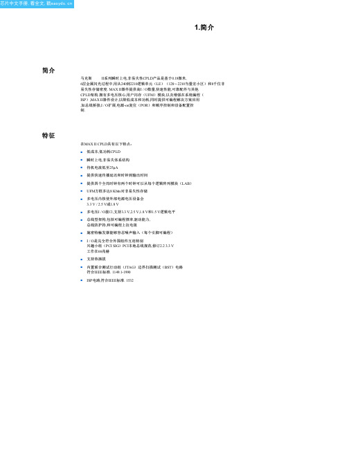
在MAX II CPLD具有以下特点: ■ 低成本,低功耗CPLD ■ 瞬时上电,非易失体系结构 ■ 待机电流低至25μA
■ 提供快速传播延迟和时钟到输出时间
■ 提供四个全局时钟有两个时钟可以从每个逻辑阵列模块(LAB) ■ UFM方框多达8 Kbits对非易失性存储
MCP2210USB转串口芯片

2011 Microchip Technology Inc.DS22288A-page 1MCP2210Features:Universal Serial Bus (USB)•Supports Full-Speed USB (12Mb/s)•Human Interface Device (HID) device•128-Byte Buffer to Handle Data Throughput:-64-byte transmit -64-byte receive•Fully Configurable VID, PID Assignments and String Descriptor (factory programming also avail-able)•Bus Powered (factory default) or Self-Powered (can be selected through special USB commands)•USB 2.0 CompliantUSB Driver and Software Support•Uses Standard HID Drivers (built-in support on Windows ® XP , Vista, 7, Linux and Mac OS ®)•Configuration Utility for Device’s Power-up Configuration•Utility for USB-SPI Communication, GPIOManipulation and Miscellaneous Features Usage SPI Master Peripheral•Supports all Four SPI modes (Mode 0, 1, 2, 3)•Bit Rates from 1500bps up to 12Mbps •Configurable Delays for SPI Transactions:-Chip Select (assert) to 1st byte of data delay -Data to data delay-Data to Chip Select (de-assert) delay•SPI Transactions Lengths of up to 65535Bytes Long•Up to 9 Chip Select lines – to be used in anycombination for a given SPI transaction (the Chip Select lines are shared between GPIOs and alternate function pins; certain GPs – up to 9 of them – can be assigned with the Chip Select functionality)General Purpose Input/Output (GPIO) Pins •Nine General Purpose I/O PinsEEPROM•256Bytes of User EEPROM (accessible through certain USB commands)Package Types:The device will be offered in the following packages:•20-lead QFN (5 x 5 mm)•20-lead SOIC •20-lead SSOPOther•USB Activity LED Output•SSPND Output Pin (to signal USB Suspend state)•USBCFG Output Pin (indicates when the enumeration is completed)•Operating Voltage: 3.3-5.5V •Oscillator Input: 12MHz•Industrial Operating Temperature: -40°C to +85°C2MCP2210SOIC,SSOPOSC2OSC1RST 123420191817V DD V SS D+D-V USB GP0516GP8GP1615GP2714GP6GP7MCP22105x5QFN*GP1GP2RST D-V USB M O S IGP8G P 4S C KG P 5GP7O S C 2O S C 1V D DV S SGP0EP 2011918173415141312678921131211MISO GP5SCKGP38MOSI 9GP410D +16GP3GP6511M I S O10* Includes Exposed Thermal Pad (EP); see Table 1-1.USB-to-SPI Protocol Converter with GPIO (Master Mode)MCP2210DS22288A-page 2 2011 Microchip Technology Inc.2011 Microchip Technology Inc.DS22288A-page 3MCP22101.0FUNCTIONAL DESCRIPTIONThe MCP2210 device is a USB-to-SPI Master converter which enables USB connectivity in applications that have an SPI interface. The device reduces external components by integrating the USB termination resistors.The MCP2210 also has 256 bytes of integrated user EEPROM.The MCP2210 has nine general purpose input/output pins. Seven pins have alternate functions to indicate USB and communication status. See Table 1-1 and Section 1.6 “GP Module” for details about the pin functions.TABLE 1-1:PINOUT DESCRIPTIONMCP2210Symbol Type S t a n d a r d F u n c t i o n (G P I O )A l t e r n a t e F u n c t i o n 1(C h i p S e l e c t s )A l t e r n a t e F u n c t i o n 2(d e d i c a t e d f u n c t i o n s )DescriptionQFNSOIC, SSOP14RST I ———Reset input25GP0I/O GPIO0CS0—General Purpose I/O 36GP1I/O GPIO1CS1—General Purpose I/O 47GP2I/O GPIO2CS2USB SuspendGeneral Purpose I/O 58GP3I/O GPIO3CS3SPI Transfer Traffic LED General Purpose I/O69MOSI O ———SPI Master output 710GP4I/O GPIO4CS4USB Low PowerGeneral Purpose I/O 811SCK O ———SPI Clock output 912GP5I/O GPIO5CS5USB ConfiguredGeneral Purpose I/O 1013MISO I ———SPI Master input 1114GP6I/O GPIO6CS6External Interrupt General Purpose I/O 1215GP7I/O GPIO7CS7SPI Bus Release ACK General Purpose I/O 1316GP8I/O GPIO8CS8SPI Bus Release REQGeneral Purpose I/O 1417V USB USB ———USB Regulator output 1518D-USB ———USB D-1619D+USB ———USB D+1720V SS GND ———Ground 181V DD P ———Power 192OSC1I ———Oscillator input 203OSC2O———Oscillator outputMCP2210DS22288A-page 4 2011 Microchip Technology Inc.1.1Supported Operating SystemsThe following operating systems are supported:•Windows XP/Vista/7•Linux •MacOS1.1.1ENUMERATIONThe MCP2210 will enumerate as a USB device after Power-on Reset (POR). The device enumerates as a Human Interface Device (HID) only.1.1.1.1Human Interface Device (HID)The MCP2210 enumerates as an HID, so the device can be configured and all the other functionalities can be controlled. A DLL package that facilitates I/O control through a custom interface is supplied by Microchip and is available on the product landing page.1.2Control ModuleThe control module is the heart of the MCP2210. All other modules are tied together and controlled via the control module. The control module manages the data transfers between the USB and the SPI, as well as command requests generated by the USB host controller, and commands for controlling the function of the SPI and I/O.1.2.1SPI INTERFACEThe control module interfaces to the SPI and USB modules.1.2.2INTERFACING TO THE DEVICEThe MCP2210 can be accessed for reading and writing via USB host commands. The device cannot be accessed and controlled via the SPI interface.1.3SPI ModuleThe MCP2210 SPI module provides the MOSI, MISO and SCK signals to the outside world. The module has the ability to control the GP pins (as Chip Select) only if these pins are configured for Chip Select operation.1.3.1SPI MODULE FEATURESThe SPI module has the following configurable features:•Bit rates •Delays•Chip Select pin assignments (up to 9 Chip Select lines)All the above features are available for customization using certain USB commands.1.3.2SPI MODULE POWER-UP CONFIGURATIONDefault parameters:•1Mbit• 4 bytes to transfer per SPI transaction •GP1 as Chip Select line1.4USB Protocol ControllerThe USB controller in the MCP2210 is full-speed USB 2.0 compliant.•HID only device used for:-SPI transfers -I/O control-EEPROM access-Chip configuration manipulation•128-byte buffer to handle data for SPI transfers -64-byte transmit -64-byte receive•Fully configurable VID, PID assignments, string descriptors (stored on-chip) and chip power-up settings (default chip settings and SPI transfer parameters)•Bus powered or self-powered1.4.1DESCRIPTORSThe string descriptors are stored internally in the MCP2210 and they can be changed so when the chip enumerates, the host gets the customer’s own product and manufacturer names. They can be customized to the user’s needs by using the Microchip provided con-figuration utility or a custom built application that will send the proper USB commands for storing the new descriptors into the chip.1.4.2USB EVENTSThe MCP2210 provides support for signaling important USB-related events such as:•USB Suspend and Resume – these states are signaled on the GP2, if the pin is configured for its dedicated function-USB Suspend mode is entered when a suspend signaling event is detected on the USB bus-USB Resume is signaled when one of the following events is occurring:a)Resume signaling is detected or generated b) A USB Reset signal is detected c) A device Reset occurs•USB device enumerated successfully (this state is signaled if the GP4 is configured for its dedicated function)•USB Low-Power modeMCP22101.5USB TransceiverThe MCP2210 has a built-in, USB 2.0, full-speed transceiver internally connected to the USB module. The USB transceiver obtains power from the V USB pin, which is internally connected to a 3.3V internal regulator. The best electrical signal quality is obtained when V USB is locally bypassed with a high-quality ceramic capacitor.The internal 3.3V regulator draws power from the V DD pin. In certain scenarios, where V DD is lower than 3.3V+ internal LDO dropout, the V USB pin must be tied to an external regulated 3.3V. This will allow the USB transceiver to work correctly, while the I/O voltage in the rest of the system can be lower than 3.3V. As an example, in a system where the MCP2210 is used and the I/O required is of 2.2V, the V DD of the chip will be tied to the 2.2V digital power rail, while the V USB pin must be connected to a regulated 3.3V power supply.1.5.1INTERNAL PULL-UP RESISTORS The MCP2210 device has built-in pull-up resistors designed to meet the requirements for full-speed USB.1.5.2MCP2210 POWER OPTIONSThe following are the main power options for the MCP2210:•USB Bus Powered (5V)•Self Powered (from 3.3V to 5V), while the V USBpin is supplied with 3.3V (regulated). If the V DD is powered with 5V, then the V USB will be poweredby the internal regulator and the V USB pin willneed only a decoupling capacitor1.5.2.1Internal Power Supply DetailsMCP2210 offers various options for power supply. To meet the required USB signaling levels, MCP2210 device incorporates an internal LDO used solely by the USB transceiver, in order to present the correct D+/D voltage levels.Figure1-1 shows the internal connections of the USB transceiver LDO in relation with the V DD power supply rail. The output of the USB transceiver LDO is tied to the V USB line.A capacitor connected to the V USB pin is required if the USB transceiver LDO provides the 3.3V supply to the transceiver.FIGURE 1-1:MCP2210 INTERNALPOWER SUPPLY DETAILS The provided V DD voltage has a direct influence on the voltage levels present on the GPIO and SPI module pins (GP8-GP0, MOSI, MISO and SCK). When V DD is 5V, all of these pins will have a logical ‘1’ around 5V with the variations specified in Section4.1 “DC Char-acteristics”.For applications that require a 3.3V logical ‘1’ level, V DD must be connected to a power supply providing the 3.3V voltage. In this case, the internal USB transceiver LDO cannot provide the required 3.3V power. It is necessary to also connect the V USB pin of the MCP2210 to the 3.3V power supply rail. This way, the USB transceiver is powered up directly from the 3.3V power supply.1.5.2.2USB Bus Powered (5V)In Bus Power Only mode, the entire power for the application is drawn from the USB (see Figure1-2). This is effectively the simplest power method for the device.FIGURE 1-2:BUS POWER ONLYLDO3.3VUSBTransceiverD+V DDV USBD-INOUTV DDV USBV SSV BUS2011 Microchip Technology Inc.DS22288A-page 5MCP2210DS22288A-page 6 2011 Microchip Technology Inc.In order to meet the inrush current requirements of the USB 2.0 specifications, the total effective capacitance appearing across V BUS and ground must be no more than 10µF. If it is more than 10 µF, some kind of inrush limiting is required. For more details on Inrush Current Limiting, see the current Universal Serial Bus Specifi-cation .According to the USB 2.0 specification, all USB devices must also support a Low-Power Suspend mode. In the USB Suspend mode, devices must consume no more than 500µA (or 2.5mA for high powered devices that are remote wake-up capable) from the 5V V BUS line of the USB cable.The host signals the USB device to enter Suspend mode by stopping all USB traffic to that device for more than 3ms.The USB bus provides a 5V voltage. However, the USB transceiver requires 3.3V for the signaling (on D+ and D- lines).During USB Suspend mode, the D+ or D- pull-up resis-tor must remain active, which will consume some of the allowed suspend current budget (500µA/2.5mA). The V USB pin is required to have an external bypass capacitor. It is recommended that the capacitor be a ceramic cap, between 0.22 and 0.47µF.Figure 1-3 shows a circuit where the MCP2210 internal LDO is used to provide 3.3V to the USB transceiver.The voltage on the V DD affects the voltage levels onto the GP and SPI module pins (GP8-GP0, MOSI, MISO and SCK). With V DD at 5V, these pins will have a logic ‘1’ of 5V with the variations specified in Section 4.1“DC Characteristics”.FIGURE 1-3:TYPICAL POWER SUPPLY OPTION USING THE 5V PROVIDED BY THE USB1.5.2.33.3V – Self PoweredTypically, many embedded applications are using 3.3V or lower power supplies. When such an option is avail-able in the target system, MCP2210 can be powered up (V DD ) from the existing power supply rail. The typi-cal connections for MCP2210 powered from 3.3V rail are shown in Figure 1-4.In this example MCP2210 has both V DD and V USB lines tied to the 3.3V rail. These tied connections disable the internal USB transceiver LDO of the MCP2210 to regulate the power supply on V USB pin. Another consequence is that the ‘1’ logical level on the GP and SPI pins will be at the 3.3V level, in accordance with the variations specified in Section 4.1 “DC Characteristics”.FIGURE 1-4:USING AN EXTERNALLY PROVIDED 3.3V POWER SUPPLYLDO 3.3VUSB TransceiverD+V DDV USBD-IN OUT5V (USB Bus)or external power supplyLDO3.3VD+V DDV USBD-IN OUT5V (USB Bus)or external power supplyExternalUSB Transceiver3.3V LDOMCP22101.6GP ModuleThe GP module features nine I/O lines.1.6.1CONFIGURABLE PIN FUNCTIONS The pins can be configured as:•GPIO – individually configurable, general purpose input or output•Chip Select pins – used by the SPI module •Alternate function pins – used for miscellaneous features such as:-SSPND – USB Suspend and Resume states-USBCFG – indicates USB configurationstatus-LOWPWR – signals when the host does notaccept the requirements (presented duringenumeration) and the chip is not configured.In this mode, the whole system powered fromthe USB host should draw up to 100 mA.-External Interrupt Input – used to countexternal events-SPI bus Release Request – used to requestSPI bus access from the MCP2210-SPI bus Release Acknowledge – used toacknowledge when the MCP2210 hasreleased the SPI bus-LED – indicates SPI traffic led1.6.1.1GPIO Pins FunctionThe GP pins (if enabled for GPIO functionality) can be used as digital inputs/outputs.These pins can be read (both inputs and outputs) and written (only the outputs).1.6.1.2Chip Select Pins FunctionThe GP pins (if enabled for the Chip Select functional-ity) are controlled by the SPI module. Their Idle/Active value is determined by the SPI transfer parameters. 1.6.1.3SSPND Pin FunctionThe GP2 pin (if enabled for this functionality) reflects the USB state (Suspend/Resume). The pin is active ‘low’ when the Suspend state has been issued by the USB host.Likewise, the pin drives ‘high’ after the Resume state is achieved.This pin allows the application to go into Low-Power mode when USB communication is suspended, and switches to a full active state when USB activity is resumed.1.6.1.4USBCFG Pin FunctionThe GP5 pin (if enabled for this functionality) starts out ‘high’ during power-up or after Reset, and goes ‘low’after the device successfully configures to the USB. The pin will go ‘high’ when in Suspend mode and ‘low’when the USB resumes.1.6.1.5LOWPWR Pin FunctionThe GP4 pin (if enabled for this functionality) starts out ‘low’ during power-up or after Reset, and goes ‘high’after the device successfully configures to the USB. The pin will go ‘low’ when in Suspend mode and ‘high’when the USB resumes.1.6.1.6External Interrupt Input Pin Function The GP4 pin (if enabled for this functionality) is used as an interrupt input pin and it will count interrupt events such as:•Falling edges•Rising edges•Low-logic pulses•High-logic pulses1.6.1.7SPI Bus Release Request PinFunctionThe GP8 pin (if enabled for this functionality) is used by an external device to request the MCP2210 to release the SPI bus. This way, more than one SPI master can have access to the SPI slave chips on the bus. When this pin is driven ‘low’, the MCP2210 will examine the request and, based on the conditions and internal logic, it might release the SPI bus. If there is an ongoing SPI transfer taking place at the moment when an external device requests the bus, MCP2210 will release it after the transfer is completed or if the USB host cancels the current SPI transfer.1.6.1.8SPI Bus Release Acknowledge PinFunctionThe GP7 pin (if enabled for this functionality) is used by the MCP2210 to signal back if the SPI bus was released. When a SPI bus release request is registered by the MCP2210, based on the condition and internal logic, the chip might release the bus. The bus is released immediately if there is no SPI transfer taking place, or it will do so after the current SPI transfer is finished or cancelled by the USB host.1.6.1.9LED Pin FunctionThe GP3 pin (if enabled for this functionality) is used as an SPI traffic indication. When an SPI transfer is taking place (active state for this pin), this pin will be driven ‘low’. When there is no SPI traffic taking place, the pin is in its inactive state or logic ‘high’.2011 Microchip Technology Inc.DS22288A-page 7MCP2210DS22288A-page 8© 2011 Microchip Technology Inc.1.7EEPROM ModuleThe EEPROM module is a 256-byte array of nonvola-tile memory. The memory locations are accessed for read/write operations solely via USB host commands.The memory cells for data EEPROM are rated to endure thousands of erase/write cycles, up to 100K for EEPROM.Data retention without refresh is conservatively estimated to be greater than 40 years.1.8Reset/POR1.8.1RESET PINThe RST pin provides a method for triggering an external Reset of the device. A Reset is generated by holding the pin low. MCP2210 has a noise filter in the Reset path which detects and ignores small pulses.1.8.2PORA POR pulse is generated on-chip whenever V DD rises above a certain threshold. This allows the device to start in the initialized state when V DD is adequate for operation.To take advantage of the POR circuitry, tie the RST pin through a resistor (1k Ω to 10k Ω) to V DD . This will eliminate external RC components usually needed to create a POR delay.When the device starts normal operation (i.e., exits the Reset condition), the device operating parameters (voltage, frequency, temperature, etc.) must be met to ensure operation. If these conditions are not achieved,the device must be held in Reset until the operating conditions are met.1.9OscillatorThe input clock must be 12MHz to provide the proper frequency for the USB module. USB full-speed is nominally 12Mb/s. The clock input accuracy is ±0.25%(2,500ppm maximum).FIGURE 1-5:QUARTZ CRYSTAL OPERATIONFIGURE 1-6:CERAMIC RESONATOR OPERATIONQuartz Crystal 12MHzOSC1OSC2R S(1)R F (2)MCP2210Note 1:A series resistor (R S ) may be required for quartz crystals with high drive level.2:The value of R F is typically between 2M Ω to 10M Ω..Example: muRata ® CSTCE12M0G15LOSC1OSC2Resonator 12MHzMCP2210MCP22102.0MCP2210 FUNCTIONALDESCRIPTIONThe MCP2210 uses NVRAM to store relevant chip settings. These settings are loaded by the chip during the power-up process and they are used for GP designation and SPI transfers.The NVRAM settings at power-up (or Reset) are loaded into the RAM portion of the chip and they can be altered through certain USB commands. This is very useful since it allows dynamic reconfiguring of the GPs or SPI transfer parameters. A practical example to illustrate this mechanism is a system which uses at least two SPI slave chips and the GPs in the MCP2210 for various GPIO purposes. The default SPI settings might be ok for one of the SPI slave chips, but not for the 2nd. At first, the PC application will make an SPI transfer to the first chip, using the NVRAM copy of the SPI settings. Then, by sending a certain USB command, the SPI transfer settings residing in RAM will be altered in order to fit the SPI transfer requirements of the second chip.Also, if the altered SPI transfer settings are needed to be the default power-up (or Reset) settings for SPI, the user can send a series of USB commands in order to store the current (RAM) SPI settings into NVRAM. In this way, these new settings will be the power-up default SPI settings.The NVRAM settings and EEPROM contents can be protected by password access means, or they can be permanently locked without any possible further modification.2.1MCP2210 NVRAM SettingsThe chip settings that can be stored in the NVRAM area are as follows:•SPI transfer parameters:-SPI bit rate-SPI mode-Idle Chip Select values-Active Chip Select values-SPI transfer configurable delays-Number of bytes to read/write for the givenSPI transfer•GP designation:-GPIO-Chip Select-Dedicated function•GPIO default direction (applies only to those GPs designated as GPIOs)•GPIO default output value (applies only to those GPs designated as output GPIOs)•Chip mode flags:-Remote wake-up capability-External Interrupt Pin mode (applies onlywhen GP6 is designated for this function)-SPI bus release enable/disable – enable/disable the release of the SPI bus when thereis no SPI transfer (useful when more thanone SPI master on the bus)•NVRAM Access mode:-Full access (no protection – factory default)-Password protection-Permanently locked•Password (relevant when password protection mechanism is active)The specified settings are loaded at power-up or Reset moments, and they can be altered through certain USB commands.When a NVRAM conditional access method is already in place, such as password protection, the NVRAM settings modification is permitted only when the user has supplied the correct password for the chip. The RAM settings can be altered even when a password protection or permanent lock mechanism are in place. This allows the user to communicate with various SPI slave chips without knowing the password, but it will not allow the modification of the power-up default settings in NVRAM.2.2SPI TransfersThe MCP2210 device provides advanced SPI communication features such as configurable delays and multiple Chip Select support.The configurable delays are related to certain aspects of the SPI transfer:•The delay between the assertion of Chip Select(s) and the first data byte (Figure2-1)FIGURE 2-1:CHIP SELECT TO DATA2011 Microchip Technology Inc.DS22288A-page 9MCP2210•The delay between subsequent data bytes(Figure2-2)•The delay between the end of the last byte (of theSPI transfer) and the de-assertion of the ChipSelect(s)FIGURE 2-3:DATA TO CHIP SELECTFor a particular SPI transfer, the user can choose anynumber (out of the available ones) of Chip Select pins.The SPI transfer parameters contain two fields wherethe user will specify the Chip Select values when theSPI transfer is active/idle. This mechanism allows theuser to specify any combination of Chip Select valuesfor the Idle mode and some other combination for theActive mode (SPI transfer active).DS22288A-page 10 2011 Microchip Technology Inc.3.0USB COMMANDS/RESPONSESDESCRIPTIONMCP2210 implements the HID interface for all the device-provided functionalities. The chip uses a command/response mechanism for the USB engine. This means that for every USB command sent (by the USB host) to the MCP2210, it will always reply with a response packet.The MCP2210 USB commands can be grouped by their provided features as follows:•NVRAM Settings-Read/Write NVRAM related parameters-Send access password •Read/Write RAM Settings (copied from NVRAM at power-up or Reset):-Read/Write (volatile – RAM stored settings)SPI transfer settings-Read/Write (volatile – RAM stored settings)chip settings-Read/Write (volatile – RAM stored settings)GPIO direction-Read/Write (volatile – RAM stored settings)GPIO output values•Read/Write EEPROM Memory•External Interrupt Pin (GP6) Event Status•SPI Data Transfer:-Read/Write SPI transfer data-Cancels the ongoing SPI transfer-SPI bus release manipulation•Chip Status and Unsupported commands3.1NVRAM SettingsThe commands in this category are related to the NVRAM settings manipulation. 3.1.1SET CHIP SETTINGS POWER-UP DEFAULTTABLE 3-1:COMMAND STRUCTUREByte Index Meaning 00x60 – Set Chip NVRAM Parameters – command code10x20 – Set Chip Settings Power-up Default – sub-command code 20x00 – Reserved30x00 – Reserved4GP0 Pin Designation•GPIO = 0x00•Chip Selects = 0x01•Dedicated Function pin = 0x025GP1 Pin Designation•GPIO = 0x00•Chip Selects = 0x01•Dedicated Function pin = 0x026GP2 Pin Designation•GPIO = 0x00•Chip Selects = 0x01•Dedicated Function pin = 0x027GP3 Pin Designation•GPIO = 0x00•Chip Selects = 0x01•Dedicated Function pin = 0x028GP4 Pin Designation•GPIO = 0x00•Chip Selects = 0x01•Dedicated Function pin = 0x02TABLE 3-1:COMMAND STRUCTURE (CONTINUED)Byte Index Meaning9GP5 Pin Designation•GPIO = 0x00•Chip Selects = 0x01•Dedicated Function pin = 0x0210GP6 Pin Designation•GPIO = 0x00•Chip Selects = 0x01•Dedicated Function pin = 0x0211GP7 Pin Designation•GPIO = 0x00•Chip Selects = 0x01•Dedicated Function pin = 0x0212GP8 Pin Designation•GPIO = 0x00•Chip Selects = 0x01•Dedicated Function pin = 0x0213Default GPIO Output – 16-bit value (low byte):•MSB – – – – – – LSBGP7VAL GP6VAL GP5VAL GP4VAL GP3VAL GP2VAL GP1VAL GP0VAL 14Default GPIO Output – 16-bit value (high byte):•MSB – – – – – – LSBx x x x x x x GP8VALwhere x = Don’t Care15Default GPIO Direction – 16-bit value (low byte):•MSB – – – – – – LSBGP7DIR GP6DIR GP5DIR GP4DIR GP3DIR GP2DIR GP1DIR GP0DIR 16Default GPIO Direction – 16-bit value (high byte):•MSB – – – – – – LSBx x x x x x x GP8DIR3.1.1.1Responses17Other Chip Settings – Enable/Disable Wake-up, Interrupt Counting, SPI Bus Release Options •Bit 7 – Don’t Care •Bit 6 – Don’t Care •Bit 5 – Don’t Care•Bit 4 – Remote Wake-up Enabled/Disabled -0 – Remote Wake-up Disabled -1 – Remote Wake-up Enabled•Bit 3 – Dedicated Function – Interrupt Pin mode •Bit 2 – Dedicated Function – Interrupt Pin mode •Bit 1 – Dedicated Function – Interrupt Pin mode -b111 – Reserved -b110 – Reserved -b101 – Reserved-b100 – Count High Pulses -b011 – Count Low Pulses -b010 – Count Rising Edges -b001 – Count Falling Edges -b000 – No Interrupt Counting •Bit 0 – SPI Bus Release Enable-0 = SPI Bus is Released Between Transfer-1 = SPI Bus is Not Released by the MCP2210 between transfers 18NVRAM Chip Parameters Access Control •0x00 – Chip settings not protected•0x40 – Chip settings protected by password access •0x80 – Chip settings permanently locked 19New Password Character 0 (Note 1)20New Password Character 1 (Note 1)21New Password Character 2 (Note 1)22New Password Character 3 (Note 1)23New Password Character 4 (Note 1)24New Password Character 5 (Note 1)25New Password Character 6 (Note 1)26New Password Character 7 (Note 1)27-63Reserved (fill with 0x00)Note 1:When the password does not need to change, this field must be filled with 0 (it applies to (byte index 19 to 26).TABLE 3-2:RESPONSE 1 STRUCTUREByte Index Meaning00x60 –Set Chip NVRAM Parameters – echos back the given command code10xFB – Blocked Access – The provided password is not matching the one stored in the chip, or thesettings are permanently locked.2-63Don’t CareTABLE 3-1:COMMAND STRUCTURE (CONTINUED)Byte IndexMeaning。
DMC2210软件手册V1.2
目录
第一章 概述 .................................................................................................................................1
第二章 软件安装 .........................................................................................................................2 2.1 安装 DMC2210 运动控制卡驱动程序..................................................................................... 2 2.1.1 先安装驱动程序,后安装控制卡的安装方法 ................................................................... 2 2.1.2 先安装控制卡,后安装驱动程序的安装方法 ................................................................. 4 2.2 安装 Motion2210 软件和编程示例......................................................................................... 4
DMC2210 PCI 总线 2 轴运动控制卡
软件使用手册
Version 1.2
©Co Co.,Ltd. All Rights Reserved. 版权说明
SSM2211

5.2 100 0.1
ELECTRICAL CHARACTERISTICS (V = ؉2.7 V, T = ؉25؇C, R = 8 ⍀, C
Parameter GENERAL CHARACTERISTICS Differential Output Offset Voltage Output Impedence SHUTDOWN CONTROL Input Voltage High Input Voltage Low POWER SUPPLY Supply Current Supply Current, Shutdown Mode AUDIO PERFORMANCE Total Harmonic Distortion
IN – IN +
Low Distortion 1.5 Watt Audio Power Amplifier SSM2211*
FUNCTIONAL BLOCK DIAGRAM
V+
VOUT A
VOUT B BYPASS SHUTDOWN BIAS
V – (GND)
The SSM2211 is a high performance audio amplifier that delivers 1 W RMS of low distortion audio power into a bridge-connected 8 Ω speaker load, (or 1.5 W RMS into 4 Ω load). It operates over a wide temperature range and is specified for single-supply voltages between 2.7 V and 5.5 V. When operating from batteries, it will continue to operate down to 1.75 V. This makes the SSM2211 the best choice for unregulated applications such as toys and games. Featuring a 4 MHz bandwidth, distortion below 0.2 % THD @ 1 W, and the patented Thermal Coastline leadframe, superior performance is delivered at higher power or lower speaker load impedance than competitive units. The advanced mechanical packaging of the SSM2211 gives lower chip temperature, which ensures highly reliable operation and enhanced trouble free life.