L9222-D中文资料
SN74LS122D中文资料
PRODUCTION DATA information is current as of publication date.Products conform to specifications per the terms of Texas Instrumentsstandard warranty. Production processing does not necessarily includetesting of all parameters.1POST OFFICE BOX 655303 • DALLAS, TEXAS 752652POST OFFICE BOX 655303 • DALLAS, TEXAS 752653 POST OFFICE BOX 655303 • DALLAS, TEXAS 752654POST OFFICE BOX 655303 • DALLAS, TEXAS 752655 POST OFFICE BOX 655303 • DALLAS, TEXAS 752656POST OFFICE BOX 655303 • DALLAS, TEXAS 752657 POST OFFICE BOX 655303 • DALLAS, TEXAS 752658POST OFFICE BOX 655303 • DALLAS, TEXAS 752659 POST OFFICE BOX 655303 • DALLAS, TEXAS 75265PACKAGING INFORMATIONOrderable Device Status (1)Package Type Package DrawingPins Package Qty Eco Plan (2)Lead/Ball FinishMSL Peak Temp (3)5962-7603901VEA ACTIVE CDIP J 161None Call TI Level-NC-NC-NC 5962-7603901VFAACTIVE CFP W 161None Call TI Level-NC-NC-NC 7603901EA ACTIVE CDIP J 161None Call TI Level-NC-NC-NC 7603901FA ACTIVE CFP W 161None Call TI Level-NC-NC-NC JM38510/01203BEA ACTIVE CDIP J 161None Call TI Level-NC-NC-NC JM38510/31401B2A ACTIVE LCCC FK 201None Call TI Level-NC-NC-NC JM38510/31401BEA ACTIVE CDIP J 161None Call TI Level-NC-NC-NC JM38510/31401BFAACTIVE CFP W 161None Call TI Level-NC-NC-NC SN54122J OBSOLETE CDIP J 14None Call TI Call TISN54123J ACTIVE CDIP J 161None Call TI Level-NC-NC-NC SN54LS123J ACTIVE CDIP J 161None Call TI Level-NC-NC-NC SN74122N OBSOLETE PDIP N 14None Call TI Call TISN74123N ACTIVE PDIP N 1625Pb-Free (RoHS)CU NIPDAU Level-NC-NC-NC SN74123N3OBSOLETE PDIP N 16None Call TI Call TISN74LS122D ACTIVE SOIC D 1450Pb-Free (RoHS)CU NIPDAU Level-2-260C-1YEAR/Level-1-235C-UNLIM SN74LS122DR ACTIVE SOIC D 142500Pb-Free (RoHS)CU NIPDAU Level-2-260C-1YEAR/Level-1-235C-UNLIM SN74LS122N ACTIVE PDIP N 1425Pb-Free (RoHS)CU NIPDAU Level-NC-NC-NC SN74LS122N3OBSOLETE PDIP N 14None Call TI Call TISN74LS122NSR ACTIVE SO NS 142000Pb-Free (RoHS)CU NIPDAU Level-2-260C-1YEAR/Level-1-235C-UNLIM SN74LS123D ACTIVE SOIC D 1640Pb-Free (RoHS)CU NIPDAU Level-2-260C-1YEAR/Level-1-235C-UNLIM SN74LS123DR ACTIVE SOIC D 162500Pb-Free (RoHS)CU NIPDAU Level-2-260C-1YEAR/Level-1-235C-UNLIM SN74LS123J OBSOLETE CDIP J 16None Call TI Call TISN74LS123N ACTIVE PDIP N 1625Pb-Free (RoHS)CU NIPDAU Level-NC-NC-NC SN74LS123N3OBSOLETE PDIP N 16None Call TI Call TISN74LS123NSR ACTIVE SO NS 162000Pb-Free (RoHS)CU NIPDAU Level-2-260C-1YEAR/Level-1-235C-UNLIM SNJ54122J OBSOLETE CDIP J 14None Call TI Call TISNJ54123J ACTIVE CDIP J 161None Call TI Level-NC-NC-NC SNJ54123W ACTIVE CFP W 161None Call TI Level-NC-NC-NC SNJ54LS123FK ACTIVE LCCC FK 201None Call TI Level-NC-NC-NC SNJ54LS123J ACTIVE CDIP J 161None Call TI Level-NC-NC-NC SNJ54LS123WACTIVECFPW161NoneCall TILevel-NC-NC-NC(1)The marketing status values are defined as follows:ACTIVE:Product device recommended for new designs.LIFEBUY:TI has announced that the device will be discontinued,and a lifetime-buy period is in effect.NRND:Not recommended for new designs.Device is in production to support existing customers,but TI does not recommend using this part in a new design.PREVIEW:Device has been announced but is not in production.Samples may or may not be available.PACKAGE OPTION ADDENDUM28-Feb-2005Addendum-Page 1元器件交易网OBSOLETE:TI has discontinued the production of the device.(2)Eco Plan -May not be currently available -please check /productcontent for the latest availability information and additional product content details.None:Not yet available Lead (Pb-Free).Pb-Free (RoHS):TI's terms "Lead-Free"or "Pb-Free"mean semiconductor products that are compatible with the current RoHS requirements for all 6substances,including the requirement that lead not exceed 0.1%by weight in homogeneous materials.Where designed to be soldered at high temperatures,TI Pb-Free products are suitable for use in specified lead-free processes.Green (RoHS &no Sb/Br):TI defines "Green"to mean "Pb-Free"and in addition,uses package materials that do not contain halogens,including bromine (Br)or antimony (Sb)above 0.1%of total product weight.(3)MSL,Peak Temp.--The Moisture Sensitivity Level rating according to the JEDECindustry standard classifications,and peak solder temperature.Important Information and Disclaimer:The information provided on this page represents TI's knowledge and belief as of the date that it is provided.TI bases its knowledge and belief on information provided by third parties,and makes no representation or warranty as to the accuracy of such information.Efforts are underway to better integrate information from third parties.TI has taken and continues to take reasonable steps to provide representative and accurate information but may not have conducted destructive testing or chemical analysis on incoming materials and chemicals.TI and TI suppliers consider certain information to be proprietary,and thus CAS numbers and other limited information may not be available for release.In no event shall TI's liability arising out of such information exceed the total purchase price of the TI part(s)at issue in this document sold by TI to Customer on an annualbasis.PACKAGE OPTION ADDENDUM 28-Feb-2005Addendum-Page 2IMPORTANT NOTICETexas Instruments Incorporated and its subsidiaries (TI) reserve the right to make corrections, modifications, enhancements, improvements, and other changes to its products and services at any time and to discontinue any product or service without notice. Customers should obtain the latest relevant information before placing orders and should verify that such information is current and complete. All products are sold subject to TI’s terms and conditions of sale supplied at the time of order acknowledgment.TI warrants performance of its hardware products to the specifications applicable at the time of sale in accordance with TI’s standard warranty. T esting and other quality control techniques are used to the extent TI deems necessary to support this warranty. Except where mandated by government requirements, testing of all parameters of each product is not necessarily performed.TI assumes no liability for applications assistance or customer product design. Customers are responsible for their products and applications using TI components. T o minimize the risks associated with customer products and applications, customers should provide adequate design and operating safeguards.TI does not warrant or represent that any license, either express or implied, is granted under any TI patent right, copyright, mask work right, or other TI intellectual property right relating to any combination, machine, or process in which TI products or services are used. Information published by TI regarding third-party products or services does not constitute a license from TI to use such products or services or a warranty or endorsement thereof. Use of such information may require a license from a third party under the patents or other intellectual property of the third party, or a license from TI under the patents or other intellectual property of TI.Reproduction of information in TI data books or data sheets is permissible only if reproduction is without alteration and is accompanied by all associated warranties, conditions, limitations, and notices. Reproduction of this information with alteration is an unfair and deceptive business practice. TI is not responsible or liable for such altered documentation.Resale of TI products or services with statements different from or beyond the parameters stated by TI for that product or service voids all express and any implied warranties for the associated TI product or service and is an unfair and deceptive business practice. TI is not responsible or liable for any such statements. Following are URLs where you can obtain information on other Texas Instruments products and application solutions:Products ApplicationsAmplifiers Audio /audioData Converters Automotive /automotiveDSP Broadband /broadbandInterface Digital Control /digitalcontrolLogic Military /militaryPower Mgmt Optical Networking /opticalnetwork Microcontrollers Security /securityTelephony /telephonyVideo & Imaging /videoWireless /wirelessMailing Address:Texas InstrumentsPost Office Box 655303 Dallas, Texas 75265Copyright 2005, Texas Instruments Incorporated。
SCLS122D芯片说明书

SN54HC193, SN74HC1934ĆBIT SYNCHRONOUS UP/DOWN COUNTERS(DUAL CLOCK WITH CLEAR)SCLS122D − DECEMBER 1982 − REVISED OCTOBER 20031POST OFFICE BOX 655303 •DALLAS, TEXAS 75265D Wide Operating Voltage Range of 2 V to 6 V D Outputs Can Drive Up To 10 LSTTL Loads D Low Power Consumption, 80-µA Max I CC D Typical t pd = 20 nsD ±4-mA Output Drive at 5 VDLow Input Current of 1 µA MaxD Look-Ahead Circuitry Enhances Cascaded CountersD Fully Synchronous in Count ModesD Parallel Asynchronous Load for Modulo-N Count LengthsDAsynchronous Clear12345678161514131211109B Q B Q A DOWNUP Q C Q D GNDV CC A CLR BO CO LOAD C DSN54HC193...J OR W PACKAGESN74HC193...D, N, NS, OR PW PACKAGE(TOP VIEW)3212019910111213456781817161514CLR BO NC CO LOADQ A DOWNNC UP Q CQ B N C D CV ADG N D N C SN54HC193...FK PACKAGE(TOP VIEW)NC − No internal connectionBC CQ description/ordering informationThe ’HC193 devices are 4-bit synchronous, reversible, up/down binary counters.Synchronous operation is provided by having all flip-flops clocked simultaneously so that the outputs change coincidentally with each other when so instructed by the steering logic. This mode of operation eliminates the output counting spikes normally associated with asynchronous (ripple-clock) counters.ORDERING INFORMATIONT APACKAGE †ORDERABLE PART NUMBER TOP-SIDE MARKING PDIP − N Tube of 25SN74HC193N SN74HC193NTube of 40SN74HC193D Reel of 2500SN74HC193DR SOIC − DReel of 250SN74HC193DT HC193−40°C to 85°CSOP − NS Reel of 2000SN74HC193NSR HC193Tube of 90SN74HC193PW Reel of 2000SN74HC193PWR TSSOP − PW Reel of 250SN74HC193PWT HC193CDIP − JTube of 25SNJ54HC193J SNJ54HC193J °°CFP − W Tube of 150SNJ54HC193W SNJ54HC193W −55C to 125CLCCC − FKTube of 55SNJ54HC193FKSNJ54HC193FK †Package drawings, standard packing quantities, thermal data, symbolization, and PCB design guidelines are available at /sc/package.Please be aware that an important notice concerning availability, standard warranty, and use in critical applications of Texas Instruments semiconductor products and disclaimers thereto appears at the end of this data sheet.Copyright 2003, Texas Instruments IncorporatedPRODUCTION DATA information is current as of publication date.Products conform to specifications per the terms of Texas Instruments standard warranty. Production processing does not necessarily include testing of all parameters.On products compliant to MILĆPRFĆ38535, all parameters are tested unless otherwise noted. On all other products, production processing does not necessarily include testing of all parameters.SN54HC193, SN74HC1934ĆBIT SYNCHRONOUS UP/DOWN COUNTERS (DUAL CLOCK WITH CLEAR)SCLS122D − DECEMBER 1982 − REVISED OCTOBER 20032POST OFFICE BOX 655303 •DALLAS, TEXAS 75265description/ordering information (continued)The outputs of the four flip-flops are triggered on a low-to-high-level transition of either count (clock) input (UP or DOWN). The direction of counting is determined by which count input is pulsed while the other count input is high.All four counters are fully programmable; that is, each output may be preset to either level by placing a low on the load (LOAD) input and entering the desired data at the data inputs. The output changes to agree with the data inputs independently of the count pulses. This feature allows the counters to be used as modulo-N dividers simply by modifying the count length with the preset inputs.A clear (CLR) input has been provided that forces all outputs to the low level when a high level is applied. The clear function is independent of the count and LOAD inputs.These counters were designed to be cascaded without the need for external circuitry. The borrow (BO) output produces a low-level pulse while the count is zero (all outputs low) and DOWN is low. Similarly, the carry (CO)output produces a low-level pulse while the count is maximum (9 or 15), and UP is low. The counters then can be cascaded easily by feeding BO and CO to DOWN and UP , respectively, of the succeeding counter.SN54HC193, SN74HC1934ĆBIT SYNCHRONOUS UP/DOWN COUNTERS(DUAL CLOCK WITH CLEAR)SCLS122D − DECEMBER 1982 − REVISED OCTOBER 20033POST OFFICE BOX 655303 •DALLAS, TEXAS 75265logic diagram (positive logic)Pin numbers shown are for the D, J, N, NS, PW, and W packages.S C11D R791145141213Q DBOLOADCO CLR DS C11D R610Q CCS C11D R21Q BBS C11D R315Q A AUP DOWN S RSN54HC193, SN74HC1934ĆBIT SYNCHRONOUS UP/DOWN COUNTERS (DUAL CLOCK WITH CLEAR)SCLS122D − DECEMBER 1982 − REVISED OCTOBER 20034POST OFFICE BOX 655303 •DALLAS, TEXAS 75265typical clear, load, and count sequenceThe following sequence is illustrated below:1.Clear outputs to 02.Load (preset) to binary 133.Count up to 14, 15, carry, 0, 1, and 24.Count down to 1, 0, borrow, 15, 14, and 13Data InputsData OutputsLOADA B C D UP CO Q A Q B Q C Q D Clear Count Up1314012BOCount Down151413DOWNCLR 1510PresetNOTES: A.CLR overrides LOAD, data, and count inputs.B.When counting up, count-down input must be high; when counting down, count-up input must be high.SN54HC193, SN74HC1934ĆBIT SYNCHRONOUS UP/DOWN COUNTERS(DUAL CLOCK WITH CLEAR)SCLS122D − DECEMBER 1982 − REVISED OCTOBER 20035POST OFFICE BOX 655303 •DALLAS, TEXAS 75265absolute maximum ratings over operating free-air temperature range (unless otherwise noted)†Supply voltage range, V CC −0.5 V to 7 V . . . . . . . . . . . . . . . . . . . . . . . . . . . . . . . . . . . . . . . . . . . . . . . . . . . . . . . . . . Input clamp current, I IK (V I < 0 or V I > V CC ) (see Note 1) ±20 mA . . . . . . . . . . . . . . . . . . . . . . . . . . . . . . . . . . . . Output clamp current, I OK (V O < 0 or V O > V CC ) (see Note 1) ±20 mA . . . . . . . . . . . . . . . . . . . . . . . . . . . . . . . . Continuous output current, I O (V O = 0 to V CC ) ±25 mA . . . . . . . . . . . . . . . . . . . . . . . . . . . . . . . . . . . . . . . . . . . . . . Continuous current through V CC or GND ±50 mA . . . . . . . . . . . . . . . . . . . . . . . . . . . . . . . . . . . . . . . . . . . . . . . . . . . Package thermal impedance, θJA (see Note 2):D package 73°C/W. . . . . . . . . . . . . . . . . . . . . . . . . . . . . . . . . . . N package 67°C/W . . . . . . . . . . . . . . . . . . . . . . . . . . . . . . . . . . . NS package 64°C/W . . . . . . . . . . . . . . . . . . . . . . . . . . . . . . . . . PW package 108°C/W. . . . . . . . . . . . . . . . . . . . . . . . . . . . . . . . Storage temperature range, T stg −65°C to 150°C. . . . . . . . . . . . . . . . . . . . . . . . . . . . . . . . . . . . . . . . . . . . . . . . . . . †Stresses beyond those listed under “absolute maximum ratings” may cause permanent damage to the device. These are stress ratings only, and functional operation of the device at these or any other conditions beyond those indicated under “recommended operating conditions” is not implied. Exposure to absolute-maximum-rated conditions for extended periods may affect device reliability.NOTES: 1.The input and output voltage ratings may be exceeded if the input and output current ratings are observed.2.The package thermal impedance is calculated in accordance with JESD 51-7.recommended operating conditions (see Note 3)SN54HC193SN74HC193MINNOMMAXMIN NOMMAXUNIT V CC Supply voltage 256256VV CC = 2 V 1.5 1.5V V CC = 4.5 V 3.15 3.15IHHigh-level input voltageV CC = 6 V 4.24.2VV CC = 2 V0.50.5V V CC = 4.5 V 1.35 1.35IL Low-level input voltage V CC = 6 V1.8 1.8V V I Input voltage 0V CC 0V CC V V O Output voltage0V CC 0V CC V V CC = 2 V 10001000V CC = 4.5 V 500500∆t/∆v ‡Input transition rise/fall timeV CC = 6 V 400400ns T A Operating free-air temperature −55125−4085°C NOTE 3:All unused inputs of the device must be held at V CC or GND to ensure proper device operation. Refer to the TI application report,Implications of Slow or Floating CMOS Inputs , literature number SCBA004.‡If this device is used in the threshold region (from V IL max = 0.5 V to V IH min = 1.5 V), there is a potential to go into the wrong state from induced grounding, causing double clocking. Operating with the inputs at t t = 1000 ns and V CC = 2 V does not damage the device; however, functionally,the CLK inputs are not ensured while in the shift, count, or toggle operating modes.SN54HC193, SN74HC1934ĆBIT SYNCHRONOUS UP/DOWN COUNTERS (DUAL CLOCK WITH CLEAR)SCLS122D − DECEMBER 1982 − REVISED OCTOBER 20036POST OFFICE BOX 655303 •DALLAS, TEXAS 75265electrical characteristics over recommended operating free-air temperature range (unless otherwise noted)V CC T A = 25°C SN54HC193SN74HC193PARAMETERTEST CONDITIONSMIN TYP MAX MIN MAXMIN MAXUNIT2 V1.9 1.998 1.9 1.9I OH = −20 µA4.5 V 4.4 4.499 4.4 4.46 V5.9 5.999 5.9 5.9V OHV I = V IH or V ILI OH = −4 mA 4.5 V 3.98 4.3 3.7 3.84VI OH = −5.2 mA 6 V 5.485.8 5.25.342 V 0.0020.10.10.1I OL = 20 µA4.5 V 0.0010.10.10.16 V 0.0010.10.10.1V OLV I = V IH or V ILI OL = 4 mA 4.5 V 0.170.260.40.33V I OL = 5.2 mA6 V 0.150.260.40.33I I V I = V CC or 0 6 V ±0.1±100±1000±1000nA I CC V I = V CC or 0,I O = 06 V 816080µA C i2 V to 6 V3101010pF timing requirements over recommended operating free-air temperature range (unless otherwisenoted)V CC T A = 25°C SN54HC193SN74HC193MIN MAXMINMAX MINMAX UNIT2 V4.2 2.8 3.3clock4.5 V 211417f Clock frequency6 V 241619MHz 2 V1201801504.5 V 243630CLR high6 V 2131262 V120180150t w4.5 V 243630Pulse durationLOAD low6 V 213126ns2 V120180150UP or DOWN high or low4.5 V 2436306 V 2131262 V1101651404.5 V 223328Data before LOAD inactive6 V 1928242 V110165140t su4.5 V 223328Setup timeCLR inactive before UP ↑ or DOWN ↑6 V 192824ns 2 V110165140↑ or DOWN ↑4.5 V 223328LOAD inactive before UP 6 V 1928242 V555t h4.5 V 555Hold timeData after LOAD inactive6 V555nsSN54HC193, SN74HC1934ĆBIT SYNCHRONOUS UP/DOWN COUNTERS(DUAL CLOCK WITH CLEAR)SCLS122D − DECEMBER 1982 − REVISED OCTOBER 20037POST OFFICE BOX 655303 •DALLAS, TEXAS 75265switching characteristics over recommended operating free-air temperature range, C L = 50 pF (unless otherwise noted) (see Figure 1)FROM TO V CC T A = 25°C SN54HC193SN74HC193PARAMETER(INPUT)(OUTPUT)MIN TYP MAX MIN MAXMIN MAXUNIT2 V4.28 2.8 3.3f max4.5 V 215514176 V 24601619MHz2 V751652502054.5 V 24335041UPCO6 V 202843352 V751652502054.5 V 24335041t DOWNBO6 V 20284335pd2 V 190250375315ns 4.5 V 40507563UP or DOWNAny Q 6 V 354364542 V1902603903254.5 V 40527865LOADAny Q6 V 354466552 V170240360300PHL4.5 V 36487260t CLRAny Q6 V 31416151ns 2 V387511095t t4.5 V 8152219Any6 V6131916ns operating characteristics, T A = 25°CPARAMETERTEST CONDITIONSTYP UNIT C pdPower dissipation capacitanceNo load50pFSN54HC193, SN74HC1934ĆBIT SYNCHRONOUS UP/DOWN COUNTERS (DUAL CLOCK WITH CLEAR)SCLS122D − DECEMBER 1982 − REVISED OCTOBER 20038POST OFFICE BOX 655303 •DALLAS, TEXAS 75265PARAMETER MEASUREMENT INFORMATIONVOLTAGE WAVEFORMSSETUP AND HOLD AND INPUT RISE AND FALL TIMESVOLTAGE WAVEFORMS PULSE DURATIONSt h t su50%50%50%10%10%90%90%V CC V CC0 V0 Vt rt fReferenceInputDataInput 50%High-LevelPulse50%V CC0 V50%50%V CC0 Vt wLow-LevelPulseVOLTAGE WAVEFORMSPROPAGATION DELAY AND OUTPUT TRANSITION TIMES50%50%50%10%10%90%90%V CCV OHV OL 0 Vt rt fInputIn-Phase Output50%t PLHt PHL 50%50%10%10%90%90%V OH V OLt rt f t PHL t PLH Out-of-PhaseOutputNOTES: A.C L includes probe and test-fixture capacitance.B.Phase relationships between waveforms were chosen arbitrarily. All input pulses are supplied by generators having the followingcharacteristics: PRR ≤ 1 MHz, Z O = 50 Ω, t r = 6 ns, t f = 6 ns.C.For clock inputs, f max is measured when the input duty cycle is 50%.D.The outputs are measured one at a time with one input transition per measurement.E.t PLH and t PHL are the same as t pd .Test Point From Output Under Test C L = 50 pF (see Note A)LOAD CIRCUITFigure 1. Load Circuit and Voltage WaveformsPACKAGING INFORMATION(1) The marketing status values are defined as follows:ACTIVE: Product device recommended for new designs.LIFEBUY: TI has announced that the device will be discontinued, and a lifetime-buy period is in effect.NRND: Not recommended for new designs. Device is in production to support existing customers, but TI does not recommend using this part in a new design.PREVIEW: Device has been announced but is not in production. Samples may or may not be available.OBSOLETE: TI has discontinued the production of the device.(2) RoHS: TI defines "RoHS" to mean semiconductor products that are compliant with the current EU RoHS requirements for all 10 RoHS substances, including the requirement that RoHS substance do not exceed 0.1% by weight in homogeneous materials. Where designed to be soldered at high temperatures, "RoHS" products are suitable for use in specified lead-free processes. TI may reference these types of products as "Pb-Free".RoHS Exempt: TI defines "RoHS Exempt" to mean products that contain lead but are compliant with EU RoHS pursuant to a specific EU RoHS exemption.Green: TI defines "Green" to mean the content of Chlorine (Cl) and Bromine (Br) based flame retardants meet JS709B low halogen requirements of <=1000ppm threshold. Antimony trioxide based flame retardants must also meet the <=1000ppm threshold requirement.(3) MSL, Peak Temp. - The Moisture Sensitivity Level rating according to the JEDEC industry standard classifications, and peak solder temperature.Addendum-Page 1(4) There may be additional marking, which relates to the logo, the lot trace code information, or the environmental category on the device.(5) Multiple Device Markings will be inside parentheses. Only one Device Marking contained in parentheses and separated by a "~" will appear on a device. If a line is indented then it is a continuation of the previous line and the two combined represent the entire Device Marking for that device.(6) Lead finish/Ball material - Orderable Devices may have multiple material finish options. Finish options are separated by a vertical ruled line. Lead finish/Ball material values may wrap to two lines if the finish value exceeds the maximum column width.Important Information and Disclaimer:The information provided on this page represents TI's knowledge and belief as of the date that it is provided. TI bases its knowledge and belief on information provided by third parties, and makes no representation or warranty as to the accuracy of such information. Efforts are underway to better integrate information from third parties. TI has taken and continues to take reasonable steps to provide representative and accurate information but may not have conducted destructive testing or chemical analysis on incoming materials and chemicals. TI and TI suppliers consider certain information to be proprietary, and thus CAS numbers and other limited information may not be available for release.In no event shall TI's liability arising out of such information exceed the total purchase price of the TI part(s) at issue in this document sold by TI to Customer on an annual basis.OTHER QUALIFIED VERSIONS OF SN54HC193, SN74HC193 :•Catalog : SN74HC193•Automotive : SN74HC193-Q1, SN74HC193-Q1•Military : SN54HC193NOTE: Qualified Version Definitions:•Catalog - TI's standard catalog product•Automotive - Q100 devices qualified for high-reliability automotive applications targeting zero defects•Military - QML certified for Military and Defense ApplicationsAddendum-Page 2TAPE AND REEL INFORMATIONA0B0K0WDimension designed to accommodate the component length Dimension designed to accommodate the component thickness Overall width of the carrier tape Pitch between successive cavity centersDimension designed to accommodate the component width TAPE DIMENSIONS Sprocket Holes P1*All dimensions are nominal Device Package Type Package DrawingPinsSPQ Reel Diameter (mm)Reel Width W1 (mm)A0(mm)B0(mm)K0(mm)P1(mm)W (mm)Pin1Quadrant SN74HC193DR SOICD 162500330.016.4 6.510.3 2.18.016.0Q1SN74HC193NSR SONS 162000330.016.48.210.5 2.512.016.0Q1SN74HC193PWR TSSOP PW 162000330.012.4 6.9 5.6 1.68.012.0Q1*All dimensions are nominalDevice Package Type Package Drawing Pins SPQ Length (mm)Width (mm)Height (mm) SN74HC193DR SOIC D162500340.5336.132.0 SN74HC193NSR SO NS162000356.0356.035.0 SN74HC193PWR TSSOP PW162000356.0356.035.0TUBET - Tube*All dimensions are nominalDevice Package Name Package Type Pins SPQ L (mm)W (mm)T (µm) B (mm) SN74HC193D D SOIC164050783940 4.32 SN74HC193N N PDIP162550613.9711230 4.32 SN74HC193N N PDIP162550613.9711230 4.32 SN74HC193NE4N PDIP162550613.9711230 4.32 SN74HC193NE4N PDIP162550613.9711230 4.32 SN74HC193PW PW TSSOP169053010.23600 3.5PACKAGE OUTLINESOP - 2.00 mm max heightNS0016A SOPNOTES:1. All linear dimensions are in millimeters. Dimensions in parenthesis are for reference only. Dimensioning and tolerancing per ASME Y14.5M.2. This drawing is subject to change without notice.3. This dimension does not include mold flash, protrusions, or gate burrs. Mold flash, protrusions, or gate burrs shall notexceed 0.15 mm, per side.4. This dimension does not include interlead flash. Interlead flash shall not exceed 0.25 mm, per side.EXAMPLE BOARD LAYOUTSOP - 2.00 mm max heightNS0016A SOPNOTES: (continued)5. Publication IPC-7351 may have alternate designs.6. Solder mask tolerances between and around signal pads can vary based on board fabrication site.EXAMPLE STENCIL DESIGNSOP - 2.00 mm max heightNS0016A SOPNOTES: (continued)7. Laser cutting apertures with trapezoidal walls and rounded corners may offer better paste release. IPC-7525 may have alternate design recommendations.8. Board assembly site may have different recommendations for stencil design.PACKAGE OUTLINETSSOP - 1.2 mm max heightPW0016A SMALL OUTLINE PACKAGENOTES:1. All linear dimensions are in millimeters. Any dimensions in parenthesis are for reference only. Dimensioning and tolerancing per ASME Y14.5M.2. This drawing is subject to change without notice.3. This dimension does not include mold flash, protrusions, or gate burrs. Mold flash, protrusions, or gate burrs shall not exceed 0.15 mm per side.4. This dimension does not include interlead flash. Interlead flash shall not exceed 0.25 mm per side.5. Reference JEDEC registration MO-153.EXAMPLE BOARD LAYOUTTSSOP - 1.2 mm max heightPW0016A SMALL OUTLINE PACKAGENOTES: (continued)6. Publication IPC-7351 may have alternate designs.7. Solder mask tolerances between and around signal pads can vary based on board fabrication site.EXAMPLE STENCIL DESIGNTSSOP - 1.2 mm max heightPW0016A SMALL OUTLINE PACKAGENOTES: (continued)8. Laser cutting apertures with trapezoidal walls and rounded corners may offer better paste release. IPC-7525 may have alternate design recommendations.9. Board assembly site may have different recommendations for stencil design.IMPORTANT NOTICE AND DISCLAIMERTI PROVIDES TECHNICAL AND RELIABILITY DATA (INCLUDING DATA SHEETS), DESIGN RESOURCES (INCLUDING REFERENCE DESIGNS), APPLICATION OR OTHER DESIGN ADVICE, WEB TOOLS, SAFETY INFORMATION, AND OTHER RESOURCES “AS IS” AND WITH ALL FAULTS, AND DISCLAIMS ALL WARRANTIES, EXPRESS AND IMPLIED, INCLUDING WITHOUT LIMITATION ANY IMPLIED WARRANTIES OF MERCHANTABILITY, FITNESS FOR A PARTICULAR PURPOSE OR NON-INFRINGEMENT OF THIRD PARTY INTELLECTUAL PROPERTY RIGHTS.These resources are intended for skilled developers designing with TI products. You are solely responsible for (1) selecting the appropriate TI products for your application, (2) designing, validating and testing your application, and (3) ensuring your application meets applicable standards, and any other safety, security, regulatory or other requirements.These resources are subject to change without notice. TI grants you permission to use these resources only for development of an application that uses the TI products described in the resource. Other reproduction and display of these resources is prohibited. No license is granted to any other TI intellectual property right or to any third party intellectual property right. TI disclaims responsibility for, and you will fully indemnify TI and its representatives against, any claims, damages, costs, losses, and liabilities arising out of your use of these resources.TI’s products are provided subject to TI’s Terms of Sale or other applicable terms available either on or provided in conjunction with such TI products. TI’s provision of these resources does not expand or otherwise alter TI’s applicable warranties or warranty disclaimers for TI products.TI objects to and rejects any additional or different terms you may have proposed.Mailing Address: Texas Instruments, Post Office Box 655303, Dallas, Texas 75265Copyright © 2023, Texas Instruments Incorporated。
LM2902DR中文资料
元器件交易网元器件交易网IMPORTANT NOTICETexas Instruments Incorporated and its subsidiaries (TI) reserve the right to make corrections, modifications,enhancements, improvements, and other changes to its products and services at any time and to discontinueany product or service without notice. Customers should obtain the latest relevant information before placingorders and should verify that such information is current and complete. All products are sold subject to TI’s termsand conditions of sale supplied at the time of order acknowledgment.TI warrants performance of its hardware products to the specifications applicable at the time of sale inaccordance with TI’s standard warranty. T esting and other quality control techniques are used to the extent TIdeems necessary to support this warranty. Except where mandated by government requirements, testing of allparameters of each product is not necessarily performed.TI assumes no liability for applications assistance or customer product design. Customers are responsible fortheir products and applications using TI components. T o minimize the risks associated with customer productsand applications, customers should provide adequate design and operating safeguards.TI does not warrant or represent that any license, either express or implied, is granted under any TI patent right,copyright, mask work right, or other TI intellectual property right relating to any combination, machine, or processin which TI products or services are used. Information published by TI regarding third-party products or servicesdoes not constitute a license from TI to use such products or services or a warranty or endorsement thereof.Use of such information may require a license from a third party under the patents or other intellectual propertyof the third party, or a license from TI under the patents or other intellectual property of TI.Reproduction of information in TI data books or data sheets is permissible only if reproduction is withoutalteration and is accompanied by all associated warranties, conditions, limitations, and notices. Reproductionof this information with alteration is an unfair and deceptive business practice. TI is not responsible or liable forsuch altered documentation.Resale of TI products or services with statements different from or beyond the parameters stated by TI for thatproduct or service voids all express and any implied warranties for the associated TI product or service andis an unfair and deceptive business practice. TI is not responsible or liable for any such statements.Following are URLs where you can obtain information on other Texas Instruments products and applicationsolutions:Products ApplicationsAmplifiers Audio /audioData Converters Automotive /automotiveDSP Broadband /broadbandInterface Digital Control /digitalcontrolLogic Military /militaryPower Mgmt Optical Networking /opticalnetworkMicrocontrollers Security /securityTelephony /telephonyVideo & Imaging /videoWireless /wirelessMailing Address:Texas InstrumentsPost Office Box 655303 Dallas, Texas 75265Copyright 2005, Texas Instruments Incorporated。
FLUKE 922 说明书
有限保证和责任限制 Fluke 公司保证本产品从购买之日起二年内,其材料和工艺均无任何缺陷。本项保证不 包括保险丝、一次性电池,或者因意外、疏忽、误用、改装、污染及非正常情况下的操 作或处理而造成的损坏。经销商无权以 Fluke 的名义提供其它任何保证。若要在保修期 内获得保修服务,请与您最近的 Fluke 授权服务中心联系,以获取有关产品退还的授权 信息,并将产品及故障说明寄至该服务中心。 本项保证是您唯一可以获得的补偿。除此以外,Fluke 不作其它任何明示或隐含的保 证,例如适用于某一特殊目的的隐含保证。FLUKE 不应对基于任何原因或推测的任何 特别、间接、偶发或后续的损坏或损失负责。由于某些州或国家不允许将隐含保证或偶 发或后续损失排除在外或加以限制,故上述的责任限制或许对您不适用。 Fluke Corporation P.O. Box 9090 Everett, WA 98206-9090 U.S.A.
922
用户手册
测量差压 ..................................................................................................... 测量流速 ..................................................................................................... 流速测量 ................................................................................................. 测量流量 ..................................................................................................... 设置菜单 ..................................................................................................... 清除样本数据 .............................................................................................. 调用 ............................................................................................................ 维护 ............................................................................................................ 清洁......................................................................................................... 更换电池 ................................................................................................. 规格 ............................................................................................................ 机构认证 ................................................................................................. 更换零件 ..................................................................................................... 附件和选件 ................................................................................................. 12 14 14 16 17 18 19 19 19 20 22 24 24 25
TG12232D说明

引脚
Symbol
能级
描述
1
VSS
0V
接地
2
VDD
+5V
模块正电源
3
V0
--
LCD驱动供应电压
4
A0
H/L
命令或数据选择(0:命令1:数据)
5
NC
--
空脚
6
NC
--
空脚
7
E1
H/L
使能信号(68型),读信号(80型)
如果68型的控制芯片选择为主控芯片,该引脚因该连接到微控制器的使能输出。该引脚上高电平表示微控制器选择SBN1661G_X系列。
复位脉冲之后的电压电平决定接口的时序类型。如果复位脉冲之后是高电平,68型的接口时序被选择了;如果是低电平,80型的接口时序被选择了。
因此,一个正的复位脉冲选择80型的时序,一个负的复位脉冲选择68型的接口时序。
19
LED+
+4.1V
液晶背光电源
20
LED-
0V
液晶背光接地
命令说明:
1:
2:
3:
11
DB1
H/L
12
DB2
H/L
13
DB3
H/L
14
DB4
H/L
15
DB5
H/L
16
DB6
H/L
17
DB7
H/L
18
RES
H/L
(复位RESET)硬件/RES接口类型选择。
这是一个双功能引脚。他可以复位液晶驱动芯片并且可以选择接口时序类型。
该引脚是边沿触发,不是电平触发。这就是说一个上升沿或下降沿信号就会复位芯片。
[整理]TCL照明产品编码标准.
![[整理]TCL照明产品编码标准.](https://img.taocdn.com/s3/m/a14f3293c8d376eeaeaa31ec.png)
TCL照明电器产品编码标准节能灯类X1X2X3X4X5X6X7X8X9X10X11-X12X13X1X2表示节能灯类别码:ESX3表示输入电压1220V2127V3120V4110V5100V6230V7277VX4X5X6表示灯管或灯罩的形状X4X5表示灯管外形3U 3U管LX 螺旋管G0 球形C0 柱形A0 烛形1H 单H管X6表示管径L Φ17M Φ12S Φ9X7X8X9表示功率X10X11表示色调RR 6400KRZ 5000KRL 4000KRB 3500KRN 3000KRD 2700KX12表示灯头1E40铜镀镍2E27铜镀镍3E14铜镀镍4B22铜镀镍5E26铜镀镍6E40铁镀镍7E27铁镀镍8E14铁镀镍9B22铁镀镍X13表示特征码L 低功率因数H 高功率因数单端荧光灯X1X2X3X4X5X6X7X8X9X10X11-X12X13X1X2表示单端荧光灯类别码:YDX3表示灯管启动形式:N 内启动单端荧光灯管W 外启动单端荧光灯管X4X5表示灯管形状1U 单U灯管1π单π管1H 单H管X6X7表示灯管功率X8表示灯管管径S 9或10mmM 12mmL 17mmN 14.5mmX9X10表示色温RR 6400KRZ 5000KRL 4000KRB 3500KRN 3000KRD 2700KX11X12表示灯头形式D1 G24d-1灯头座D2 G24d-2灯头座D3 G24d-3灯头座Q1 G24q-1灯头座G11 2G11灯头座X13特征码,表示单端荧光灯的灯头的定位插槽形式S 单定位槽(2G7、2G11、G23、G24)D 双定位槽(2GX7、2GX11、GX23、GX24)镇流器类X1X2X3X4X5X6X7X8X9X10X11-X12X13X1X2表示镇流器类别码:EBX3表示输入电压1220V2127V3120V4110V5100V6230V7277VX4X5X6表示镇流器型号,不足三位在前面补0 YZ 直管形荧光灯镇流器YK 快速启动荧光灯镇流器ZW 紫外线灯管镇流器YH 环形荧光灯镇流器ZSZ 直管形石英紫外线低压汞灯镇流器ZSU U形石英紫外线低压汞灯镇流器YDY 单端荧光灯一体式镇流器YDN 单端内启动荧光灯镇流器GGY 荧光高压汞灯泡镇流器GGZ 直管形紫外线高压汞灯镇流器GGQ 球形超高压汞灯镇流器GGM 毛细管超高压汞灯镇流器XQ 球形超高压汞氙灯镇流器ND 低压钠灯泡镇流器NG 高压钠灯泡镇流器JLZ 照明金属卤化物灯镇流器JTG 管形铊灯镇流器JYQ 球形铟灯镇流器JD 镝灯镇流器NTY 钠铊铟灯泡镇流器JDH 球形镝灯镇流器KN 钪钠灯镇流器X7X8表示负载灯管的功率X9表示负载灯管的数量X10表示产品的用途和外型结构Z 阻抗式镇流器R 电容式镇流器L 漏磁式镇流器D 电子式镇流器J 基准镇流器S 寿命试验用镇流器Q 启动用镇流器K 快速启动镇流器F 防腐防潮镇流器N 内装式镇流器X11表示设计顺序1超薄型(喷漆)电子镇流器2超薄型(电解板)电子镇流器3普通型(喷漆)电子镇流器4普通型(电解板)电子镇流器5灯箱用(喷漆)电子镇流器6灯箱用(电解板)电子镇流器X12表示接线类型X 引线型J 接线端子型X13表示性能特征L L级H H级变压器类X1X2X3X4X5X6X7X8X9X10X11-X12X13 X1X2表示变压器器类别码:ETX3代表输入电压1220V2127V3120V4110V5100V6230V7277VX4X5X6表示负载功率X7X8X9表示变压器外形最大长度X10X11X12表示变压器外形最大宽度X13特征码,表示输出电压值A 12VB 24VC 36V灯盘类X1X2X3X4X5X6X7X8X9X10X11-X12X13 X1X2表示灯盘类别码:MQX3X4表示材质1S 镜面电化铝2S 哑光电化铝3S 不锈钢1A 铝合金边框3A 乳白胶片3C 凌晶片X5X6表示反光面形式XX 无XP 单抛PP 双抛X7表示负载种类Y 荧光灯管B 插拔管X8X9表示灯管功率,不同负载时用最大负载功率表示X10表示负载的数目X11X12表示特征LX 豪华型SX 明装DX 吊装E1 应急1管QX 嵌装WX 宽边TX 洁净SX 吸顶式X13特征码,无特征时用X表示支架类X1X2X3X4X5X6X7X8X9X10X11-X12X13X1X2表示支架类别码:MYX3表示输入电压1220V2127V3120V4110V5100V6230V7277VX4X5表示负载灯管功率X6X7表示灯管数量X8表示种类代号,用ABCD表示X9表示颜色W 白色B 黑色L 蓝色X10X11备用代码,用XX表示X12表示应急管的数量X13特征码E 应急筒灯类X1X2X3X4X5X6X7X8X9X10X11-X12X13 X1X2表示筒灯类别码:MDX3X4表示反光杯径X5X6表示负载灯功率X7表示负载数量X8X9X10表示灯座形式:E27、E14、PLC X11表示面板颜色W 白边G 金边S 银边B 镀黑镍A 白色塑圈Z 压铸边K 亚克力罩N 镍扫纹X12表示灯杯花纹P 防雾型杯C 条杯D 点珠杯A 哑光喷砂杯N 光杯B 哑光乳白杯X13表示灯管安装形式H 横向插管用V 竖向插管用低压卤素灯杯X1X2X3X4X5X6X7X8X9X10X11-X12X13 X1X2表示低压卤素灯杯类别码:HLX3X4灯杯规格11MR1116MR16X5表示灯杯类型X6X7表示灯杯功率X8:W高压卤素灯杯X1X2X3X4X5X6X7X8X9X10X11-X12X13 X1X2表示高压卤素灯杯类别码:THX3X4灯杯规格11MR1116 MR16X5X6表示灯杯功率X7:W低压卤素灯珠X1X2X3X4X5X6X7X8X9X10X11-X12X13 X1X2表示低压卤素灯珠类别码:TG天花灯X1X2X3X4X5X6X7X8X9X10X11-X12X13 X1X2表示天花灯类别码:DLX3灯体主要材质:1钣金件2压铸件X4表示使用光源1MR116 MR16X5X6结构流水号X7X8主体颜色低压路轨射灯X1X2X3X4X5X6X7X8X9X10X11-X12X13 X1X2表示低压路轨射灯类别码:TRX3表示中间连接杆X 无杆A 杆长100mmB 杆长200mmC 杆长300mmE 杆长500mmF 代表软管,软管固定长400mmX4X5表示射灯头代码X6X7表示主体颜色低压吸顶射灯X1X2X3X4X5X6X7X8X9X10X11-X12X13 X1X2表示低压吸顶射灯类别码:SPX3表示中间连接杆X 无杆A 杆长100mmB 杆长200mmC 杆长300mmE 杆长500mmF 代表软管,软管固定长400mmX4X5表示射灯头代码X6X7表示主体颜色吊装格栅射灯X1X2X3X4X5X6X7X8X9X10X11-X12X13 X1X2表示吊装格栅射灯类别码:CHX3X4光源型号MR MR16QR QR111PL PLCX5X6X7X8表示结构款式类别X9X10表示主体颜色嵌入式格栅射灯X1X2X3X4X5X6X7X8X9X10X11-X12X13 X1X2表示嵌入式格栅射灯类别码:DOX3X4光源型号MR MR16QR QR111PL PLCX5X6X7X8表示结构款式类别X9X10表示主体颜色主体颜色代码说明:WH 烤漆白色BK 烤漆黑色SG 烤漆银灰色CH 电镀铬色SH 电镀镍扫纹SB 电镀青铜扫纹SC 电镀珍珠银间色SN 电镀珍珠镍间铬吸顶灯X1X2X3X4X5X6X7X8X9X10X11-X12X13 X1X2表示吸顶灯类别码:MXX3整灯外形C 圆形S 方形X4X5整灯功率X6灯管形状C 环形P 插拔D 双DX7镇流器种类X 电子G 电感Z E27灯头X8罩的材料Y 亚克力板P PVCB 玻璃X9罩上的花纹TCL户外灯具物料编码命名方式:X1X2X3X4X5X6X7X8X9X10X11-X12X13X1:Z 指户外产品系列X2:T 投光灯F 泛光灯Q 球场灯A 高墙灯Z 招牌灯----通用照明----L 路灯S 隧道灯----道路照明----N 工矿悬挂灯H 商业悬挂灯----悬挂照明-----D 低杆灯C 草地灯M 埋地灯U 水池灯B 壁灯O 高杆照明G 广场照明I 触发器X 电器箱----庭园照明----X3X4表示每一种产品系列流水编码00—99 X5表示光源M 金卤灯S 高压钠灯L 低压钠灯I 电子节能灯Q 高压汞灯T T8光管B 白炽灯P PAR灯E LED灯Y 太阳能电池类C 彩色金卤灯X6表示灯头形式A E27B E40C G13D G5R Rx7sF 1000w双端P PG-12G G-12Y BY22dE Fc-2X7X8X9X10表示使用功率金卤灯电子镇流器编码说明(H)/可调光(T)/输出端子(D)/输出线(X)台灯编码标准X1X2X3X4X5X6X7X8X9X10X11-X12X13X1X2 表示台灯类别码,用MT表示X3X4表示灯具编码流水号X5X6位表示光源功率X7X8表示灯管形状类别1U 单U荧光灯管2H 双H型荧光灯管1A 1个普通A型灯泡3B 3个B型蜡烛型灯泡X9X10表示灯具的颜色CY 深蓝色FI 淡黄色PI 粉红色SG 银灰色MI 粉绿色X11表示附带功能S 带时钟B 带报时钟Y 带氧吧X12X13表示识别码。
W92S11D22D-24D中文资料
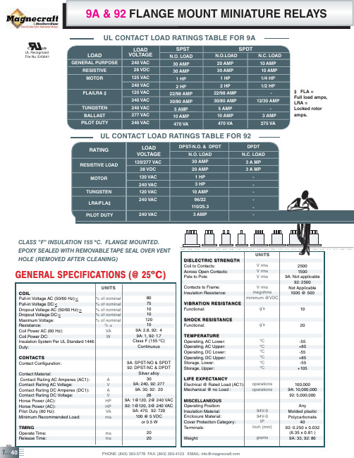
FIG. E
62 84
1
0
62 84 62
1
0
FIG. C
FIG. F
9/04
1...42
IMPROVED FLANGE COVER WITH DIN
MEETS UL 873, UL 508 AND UL 1950 - (0.125 MM) THRU AIR, (0.25 MM) OVER SURFACE
86 W 350 W 7,255 W
PHONE: (843) 393-5778 FAX: (843) 393-4123 EMAIL: info@
% of nominal
Pull-in Voltage DC:<
% of nominal
Dropout Voltage AC (50/60 Hz):>
% of nominal
Dropout Voltage DC:>
% of nominal
Maximum Voltage:
% of nominal
Resistance:
FLA/LRA
TUNGSTEN BALLAST PILOT DUTY
LOAD VOLTAGE
240 VAC 28 VDC 125 VAC
240 VAC 120 VAC 240 VAC 240 VAC 277 VAC 240 VAC
SPST N.O. LOAD
30 AMP 30 AMP
1 HP 2 HP 22/98 AMP 30/80 AMP 5 AMP 10 AMP 470 VA
Weight:
grams
9/04
1...40
PHONE: (843) 393-5778 FAX: (843) 393-4123 EMAIL: info@
RM6222D中文规格书-20120525

Web: www.reactor‐
2
2012‐05‐25
封装信息:
RM6222D
管脚分布:
1 VDDG 2 VDD 3
FB 4 SENSE
GND 8 GND 7
6 Drain Drain 5
RM6222D
管脚功能:
管脚
1 2 3 4 5、6 7、8
符号 VDDG VDD
FB SENSE DRAIN
产品概述:
RM6222D 是一款高性能电流模 式 PWM 控制器,内置高压 MOSFET 进一步提高了产品可靠性。优化的合 理性电路设计最大程度节省了产品整 体成本。离线式副边反馈应用,单电 压输入时最大输出功率可达 24W。
RM6222D 拥有多种保护功能:逐 周期限流保护、过载保护、VDD 过压 保护和欠压锁定后自动重启功能。采 用软开关控制图腾柱栅极驱动和抖频 技术,很好地抑制了 EMI,无 Y 电容 应用。最小工作频率 20KHz,有效消 除了音频噪音。
ta25vddvddg16v符号vdd供电部分i参数测试条件最小值典型值最大值单位upstart启动电流工作电流vdd145v320uaivddvfb2v16224mauvloon欠压锁定开启uvlooff欠压锁定关闭ovpon85995v14515155v过压保护272829vvddclampvdd箝位电压30v反馈输入部分vopenfbfb脚开路电压545658vshortfbifb脚短路电流151719maodthv零占空比时fb阈值电压过载fb阈值电压过载延迟时间08vplthv37vpltd50ms电流检测部分tsoft软启动时间4msblankingt前沿消隐时间电流检测基准电压300nsocthvvfb33v070809v振荡器部分fosc正常工作频率温度频率特性vdd电压与频率特性最大占空比455055khztempf5vddfvfb33vvcs0v5maxd708090hiccupf打嗝模式工作频率频率抖动范围20khzsocf44功率mosfet部分dssbvmosfet漏源击穿电压完全导通阻抗600vondsr455055rm6222dweb
- 1、下载文档前请自行甄别文档内容的完整性,平台不提供额外的编辑、内容补充、找答案等附加服务。
- 2、"仅部分预览"的文档,不可在线预览部分如存在完整性等问题,可反馈申请退款(可完整预览的文档不适用该条件!)。
- 3、如文档侵犯您的权益,请联系客服反馈,我们会尽快为您处理(人工客服工作时间:9:00-18:30)。
1/7L9222May 20041FEATURES■OUTPUT VOLTAGE TO 50V ■OUTPUT CURRENT TO 1.2A■VERY LOW SATURATION VOLTAGE ■TTL COMPATIBLE INPUTS■INTEGRAL SUPPRESSION DIODE2DESCRIPTIONThe L9222 monolithic quad transistor switch is de-signed for high current, high voltage switching ap-plications.Each of the four switches is controlled by a logic input and all four are controlled by a common en-able input. All inputs are TTL-compatible for direct connection to logic circuits. Each switch consists of an open-collector transistor plus a clamp diode for applications with inductive loads.The emitters of the four switches are connected to-gether to GND. The switches of the same device may be paralled. The device is intended to drive coils such as relays, solenoids, unipolar stepper motors, LED etc.QUAD INVERTING TRANSISTOR SWITCHFigure 2. BLOCK DIAGRAMREV. 3Figure 1. PackagesTable 1. Order CodesPart NumberPackage L9222 (PDIP12+2+2) L9222 D(SO20L)L92222/7Table 2. ABSOLUTE MAXIMUM RATINGSFigure 3. PIN CONNECTION (Top view)Table 3. TRUTH TABLEFor each input :H= High level L= Low level X = Don’t careTable 4. THERMAL DATASymbol ParameterValue Unit V OUT Output Voltage – 0.7 to 50V V CC Logic Supply Voltage 7V V i Input Voltage– 0.7 to V CC + 0.3VT j , T STJunction and Storage Temperature Range– 55 to 150°CEnable Input Power OutH L ON H H OFF LXOFFSymbol ParameterValue Unit R th j-amb Thermal Resistance Junction to ambient Max 90°C/W R th-J-caseThermal Resistance Junction to caseMax14°C/WDIP16SO20LL9222 Table 5. ELECTRICAL CHARACTERISTICSV CC = 5Vdc ± 5% V EN = 5V – 40 ≤ T j≤ 125°C unless otherwise specifiedSymbol Parameter Test Condition Min. Typ.Max.UnitV CE(sus)Output Sustaining Voltage V IN = 2V V EN= 2V, I OUT = 100mA46VI CEX Output Leakage Current V CE = 50V V IN = 2V, V EN = 0.8V1mAV CE(sat)Collector Emitter Saturation V IN≥ 0.8VI OUT = 0.1AI OUT = 0.3AI OUT = 0.6A; – 40 + 105 °C 0.30.50.8VVVV IL Input Low Voltage0.8V I IL Input Low Current V IN = 0.4V– 15µA V IH Input High Voltage 2.0V I IH Input High Current V IN≥ 2.0V– 15µA I S Logic Supply Current All Outputs ON I OUT = 06A5090mAAll Outputs OFF1020mA I R Clamp Diode Leakage Current V R = 50VDiode Reverse Voltage100µA V F Clamp Diode Forward Voltage I F = 0.6A 1.8VI F = 1.2A 2.0V I OUT Output Current V IN = 0.4V, R = 10Ω , V S = 13V0.9 1.2AT PHL Propagation Delay Time(high to low transition)T j = 25°CI L = 600mA20µsT PHL Propagation Delay Time(low to high transition)I L = 600mAT j = 25°C20µsV ENL Low Enable Voltage0.8VI ENL Low Enable Current V EN = 0.4V– 15µAV ENH High Enable Voltage 2.0VI ENH High Enable Voltage V EN≥ 2.0V– 1515µA3/7L9222Figure 4. Powerdip (12+2+2 0Mechanical Data & Package Dimensions4/7L9222 Figure 5. SO20L Mechanical Data & Package Dimensions5/7L9222Table 6. Revision HistoryDate Revision Description of Changes March 20042Second IssueMay 20043Stylesheet update. No content change6/7L9222 Information furnished is believed to be accurate and reliable. However, STMicroelectronics assumes no responsibility for the consequences of use of such information nor for any infringement of patents or other rights of third parties which may result from its use. No license is grantedby implication or otherwise under any patent or patent rights of STMicroelectronics. Specifications mentioned in this publication are subject to change without notice. This publication supersedes and replaces all information previously supplied. STMicroelectronics products are notauthorized for use as critical components in life support devices or systems without express written approval of STMicroelectronics.The ST logo is a registered trademark of STMicroelectronics.All other names are the property of their respective owners© 2004 STMicroelectronics - All rights reservedSTMicroelectronics GROUP OF COMPANIESAustralia - Belgium - Brazil - Canada - China - Czech Republic - Finland - France - Germany - Hong Kong - India - Israel - Italy - Japan - Malaysia - Malta - Morocco - Singapore - Spain - Sweden - Switzerland - United Kingdom - United States7/7。