
GEL高效送风口的安装及操作手册
高效送风口的安装及操作手册
1.高效送风口的安装
●洁净室顶板的开洞.
依照送风口箱体尺寸,在洁净房顶板相应位置划线开洞。
注:一般洞口尺寸为箱体长宽各加10MM。
●高效送风口箱体的吊装。
将箱体抬入顶板洞口,装上吊耳(此项目工程公司要求吊耳向外翻边,吊耳外尺寸大于吊顶开口尺寸,吊耳需工程公司现场安装)。
与吊顶上方丝杆或吊钩固定。
调节箱体高度至箱体下沿法兰与顶板平齐。
图1,未装吊环前
图2,装入吊顶洞口,并装上吊环
图3,装上吊装丝杆,并打胶
●箱体与顶板的密封。
箱体下沿法兰与净房顶板结合部位需打密封胶,以保证净房内气体不外泄。
●箱体保温。
如箱体外保温至顶板上方,则贴保温棉前箱体与顶板隔洞间的缝隙需加入填充料,避免箱体结露。
图4,加贴保温棉后
●风管与箱体接口的连接。
将风管与箱体进风接口相连。
使用方形外法兰接口时,需在箱体进风口外法兰沿上钻孔,并用螺栓螺母与风管法兰连接,并在连接部位填充密封材料。
使用圆形进风接口时,需用圆箍将软风管与箱体接口收紧,注意圆箍位置应在箱体进风接口防滑凸起沿内。
如箱体进风接口为侧接时,需要先将进风接口与箱体用自攻螺栓或铆钉连接固定。
●风量调节阀的安装。
如订购单包括风量调节阀,需在连接风管与高效送风口箱体前安
装好风量调节阀。
用自攻螺栓或铆钉将风量调节阀与箱体进风洞口相连,并在连接部位填充密封材料,最后在四周打胶。
注意:安装时阀体洞口与箱体洞口应保持位置一致。
此项目风口不含调节阀,风阀可安装于主风管与支风管接口处。
●箱体保温。
如箱体外保温至顶板上方,则箱体与顶板隔洞间的缝隙需加入填充料,避免箱体结露。
●过滤器的安装。
由于高效过滤器使用玻纤滤纸,滤料容易折断损坏而造成泄漏。
故搬运,拆包装,安装过程中不得摔倒或碰撞过滤器,严禁作业人员手指或其他物体接触过滤器滤料。
a)高效过滤器安装前需对箱体进行清洁及预吹处理,避免粉尘
污染过滤器,降低使用寿命。
b)将箱体内过滤器压块旋转至平行于对应边框角度(如安装示
意图),将过滤器居中装入箱体(密封垫片面应朝上与箱体
接触)。
c)将箱体内过滤器压块拉下至箱体内丝杆末端,并旋转至垂直
于对应边框角度(如安装示意图),并将四周压块分别拧紧。
d)检查每个压块螺母扭矩是否接近,如有明显松紧需进行调
整,避免过滤器边框泄漏。
图5,过滤器的安装
●散流孔板的安装。
将散流孔板盖住箱体,并用扁头螺栓与箱体连接。
2.高效送风口的操作
●DOP及压差测试口的使用。
DOP及压差测试口为可选配件。
DOP及压差测试口位于箱体内过滤器密封框一侧或箱体外框侧边一侧,以定购产品时提供图纸为准。
DOP发尘通道为选配件。
DOP测试时需使用其中的一个或两个测试口(由发尘位置确定)。
连接发尘通道的测试口的用途为,向过滤器上游发尘(如不在高效送风口箱体内发尘或未选购发尘通道,则不适用)。
另一个测试口的用途为,采样过滤器上游浓度是否达到测试标准。
同时测试口可用压差测试时过滤器上游压强点的采样点。
测试口一般适用Φ8MM软管。
测试时需将测试口上的堵头拔下,拔下时需按住测试口末端的活动沿。
再将Φ8MM测试管插入测试口。
测试完成后需将堵头插上,以免造成粒子泄漏。
格力超薄风管机使用安装说明书
键进行确认,此时“定时”不再闪烁。如再按“定
时”键可取消定时。
图7
7)当系统运行中出现故障,线控器上将显示故障
代码。如图 8 显示表明室内环境感温包故障。
故障代码意义如下:
故障代码 E1 E2 E3 F0 F1 F3 EH
故障 压缩机高压保护 室内防冻结保护 压缩机低压保护 室内环境感温包故障 蒸发器感温包故障 室外环境感温包故障 辅助电加热故障
注意! :
安装前,请检查所用的电源是否与铭牌上要求的电源一致并检查电源的安全性。 使用前,请检查并确认排水管、管路和电线的连接是否正确,以防止漏水、漏制冷剂、触电或火灾等事故 的发生。 电源插座必须配有地线,以保证空调器通过电源插座有效接地,避免发生触电危险。接地线请勿接到煤气 管、自来水管、避雷针或电话的接线上。 空调一旦开机至少要运行 5 分钟以上才能关机,否则会影响压缩机回油。 不要让小孩操作空调器。 请勿用湿手来操作空调器。 在清洁空调器或更换空气过滤网时,请先关闭空调器的电源。 长时间不使用本机时,请切断空调器的电源。 请勿让空调器直接暴露于有水或潮湿等易被腐蚀的环境下。 请勿踩在空调器上或在空调器上面放置物件。 电器安装后应通电进行漏电检测。
送风、自动模式无睡眠功能。
图5
5)运行模式设置(图 6) 每一次按下本键,操作模式按如下顺序变化:
→制冷→除湿→送风→制热→自动
制冷模式时,制冷显示 将点亮,温度必须设定成比现
自动
在的环境温度低。如果设定成比现在环境温度高,本机将
不会进入制冷方式而将只会有风扇动作。
化霜
除湿模式时,除湿显示 将点亮。内风机在一定温度范
运转
自动
换气
负 离 子
扫风 加湿 灯光 节电
高效送风口安装流程步骤

高效送风口安装流程步骤高效送风口由静压箱体、高效空气过滤器、散流板三部分组成,适用于各级别,多种屋顶结构或非层流洁净室内,应用于对洁净度要求较高的工作环境,高效送风口的安装步骤如下:第一步:高效送风口安装1、高效空气过滤器和送风口尺寸必须符合设计要求。
安装前应清洗干净。
2、在洁净室内安装和更换高效空气过滤器的送风口,风口翻边和吊顶板之间的接缝应加密封垫。
3、在技术夹层内安装和更换高效空气过滤器的风口,安装前应配合土建施工预埋短管,短管和吊顶板之间如有裂缝必须封堵好。
4、风口表面涂层破损的不得安装。
风口安装完毕应随即和风管连接好,开口端用塑料薄膜和胶带密封。
第二步:彻底清洁无尘室1、高效空气过滤器安装前,必须对洁净室进行全面清扫、擦净,净化空调系统内部如有积尘,应再次清扫、擦净,达到清洁要求。
如在技术夹层或吊顶内安装高效空气过滤器,则技术夹层或吊顶内也应进行全面清扫、擦净。
2、洁净室及净化空调系统达到清洁要求后,净化空调系统必须试运转。
连续运转12h以上,再次清扫、擦净洁净室后立即安装高效空气过滤器。
3、高效空气过滤器的运输和存放应按照生产厂标志的方向搁置。
运输过程中应轻拿轻放,防止剧烈振动和碰撞。
第三步:安装前高效空气过滤器检漏1、高效空气过滤器安装前,必须在安装现场拆开包装进行外观检查,内容包括滤纸、密封胶和框架有无损坏;2、边长、对角线和厚度尺寸是否符合要求;框架有无毛刺和锈斑(金属框);有无产品合格证,3、技术性能是否符合设计要求。
然后进行检漏。
经检查和检漏合格的应立即安装。
安装时应根据各台高效过滤器的阻力大小进行合理调配,对于单向流,同一风口或送风面上的各高效过滤器之间,每台额定阻力和各台平均阻力相差应小于5%。
第四步:高效空气过滤器安装1、安装高效空气过滤器的框架应平整。
每个高效过滤器的安装框架平整度允许偏差不大于1mm。
高效空气过滤器正确安装方式2、高效空气过滤器和框架之间的密封采用密封垫、不干胶、负压密封、液槽密封和双环密封等方法时,都必须把填料表面、过滤器边框表面和框架表面及液槽擦拭干净。
高效送风口

高效送风口
高效送风口分类:
按散流板外形:可以分为孔板、带条缝的孔板、辐射型条缝板三种;
按密封形式:基本可分为正压密封(液槽、胶条)和负压密封两种;
按调节阀调节方式:可分为上调节和下调节两种;
按是否含PAO气溶胶检测口:又可分为带检测口和不带检测口两种;
按接口的外形:可以分为圆形接口和方形接口两种;
按接口的位置:可分为顶接和侧接两种。
高效送风口安装方式
1.安装空间足够时,尽量选择顶进风的送风口。
2.送风口的表而涂层,尽量选用喷塑或烤漆的。
3.避免选用喷漆涂层(该涂层易剥落)。
4.应选用保温型的送风口。
5.扩散板应选用凸形扩散孔板。
6.尽量选用压框压紧结构的送风口,这种结构在压紧高效过滤器时受力均匀(特别是铝合金框的高效过滤器,受力不均匀是容易变形。
ITG100 天花板 墙壁通风风扇安装和操作指南说明书

General Safety Information1. Make sure that the electric service supply voltage is AC 120V, 60Hz.2.Follow all local electrical and safety codes, as well as the National Electrical Code (NEC) and the Occupational Safety and Healthy Act (OSHAct).3.Always disconnect the power source before working on or near the ventilating fan, motor or junction box.4.Protect the power cord from sharp edges, oil, grease, hot surfaces, chemicals or other objects.5. Do not kink the power cord.6. Do not install the unit where ducts are configured as shown in Fig. A.7. Provide suction parts with proper ventilation. 8.This unit is UL listed for use over a bathtub or shower when installed in a GFCI protected branch circuit.WARNINGTO REDUCE THE RISK OF FIRE, ELECTRIC SHOCK, OR INJURY TO PERSONS, OBSERVE THE FOLLOWING: 1.Use this unit only in the manner intended by the manufacturer. If you have any questions, contact the manufacturer.2.Before servicing or cleaning the unit, switch power off at service panel and lock the service disconnecting means to prevent power from being switched on accidentally. When theservice disconnecting means cannot be locked, securely fasten a prominent warning device, such as a tag, to the service panel.3.Installation work and electrical wiring must be done by qualified person(s) in accordance with all applicable codes and standards, including fire-rated construction.4.Sufficient air is needed for proper combustion and exhausting of gases through the flue(chimney) of fuel burning equipment to prevent back drafting. Follow the heating equipment manufacturer’s guideline and safety standards such as those published by the National Fire Protection Association (NFPA), and theAmerican Society for Heating, Refrigeration and Air Conditioning Engineers (ASHRAE), and the local code authorities.5.When cutting or drilling into wall or ceiling, do not damage electrical wiring and other hidden utilities.6. Ducted fans must always be vented to the outdoors.7.If this unit is to be installed over a tub or shower, it must be marked as appropriate for the application and be connected to a GFCI(Ground Fault Circuit Interrupter) – protected branch circuit.8.Do not use this unit with any other solid-state control device. Solid-state controls devices may cause harmonic distortion, which can cause a motor humming noise.9.NEVER place a switch where it can be reached from a tub or shower.10. Not to be installed in a ceiling thermallyinsulated to a value greater than R50. (This is required for installation in Canada only).CAUTION1.For General Ventilating Use Only. Do Not Use To Exhaust Hazardous Or Explosive Materials And Vapors.2. Not for use in cooking area. (Fig. B)3. This product must properly connect to the grounding conductor of the supply circuit.4.To reduce the risk of injury to persons, install the fan at least 8.2 feet (2.5m) above the floor.SUPPLIED ACCESSORIESINSTALLATIONSProper insulation around the fan to minimize building heat loss and gain. 4” circular duct is recommended for installation. The ducting from this fan to theoutside of building has a strong effect on the air flow, noise and energy use of the fan. Use the shortest, straightest duct routing possible for best performance, and avoid installing the fan with smaller ducts than recommended. Insulation around the ducts can reduce energy loss and inhibit mold growth. Fans installed with existing ducts may not achieve their rated air flow.Install with wood frameModel No. ITG100 Install Dim. (Inch)7-1/2 x 7-1/41. Remove motor plate from housing by removing three screws. (Fig. C)2.Remove wiring cover from housing by pulling straight out. Choose a hole and use a slotted screwdriver to remove it. (Fig. D)3.Follow all local electrical and safety codes. NEVER place a switch where it can bereached from a tub or shower. Connect wires as shown in wiring diagrams. (Fig. E) 4.Using wire nuts(not provided), connect house power cable to ventilating fan wires. 14 AWG (2.1 mm 2) is the smallest conductor that shall be used for branch-circuit wiring. (Fig. F) 5.Insert the duct into the duct connector and tape all ductworks connection to make them secure and airtight. Install the duct with a gradient 1°~2° to the outside. (Fig. G) 6.New installation prior to finishing theceiling or wall: Insert the fan between joists. Make sure the fan body is level and perpendicular with the joist. (Fig. H)7.Replacement installation: After makingelectrical and ductwork connections (see steps 2~5), nail housing in place. Drive nails through the housing where indicated by arrows. (Fig. I) 8.New installation in an existing ceiling or wall: Bend tabs outward 90°(Use a screw driver if desired) and position housing so that tabs rest against bottom edge of joists (or front of stud). Nail housing to joist or stud using four nails to ensure a solid, quiet installation.Ceiling installations: Tabs on opposite side of housing can be bent outward to rest on top of 1/2" ceiling material and provide extra stability. (Fig. J)9.Plug in the motor and locking the fan body back by using three screws. (Fig. C)10. Squeeze grille springs together and insertsprings into slots in motor plate. Push grille up against ceiling or wall. When the power on,Fig. Bthe mounting springs into the slots and mount the grille to the body. (Fig. K)OPERATIONSingle speed control mode: Turn the power switch to operate ON/OFF.MAINTENANCE:Disconnect the power source before working on the unit. Routine maintenance must be done every year.CAUTION:1. Never use gasoline, benzene, thinner or anyother such chemicals for cleaning the ventilating fan.2. Do not allow water to enter the motor.3.Do not soak resin parts in water over 140 o F (60°C).CLEANING:1. Pull down the spring to remove the grille.2.Wash and clean the grille. (Use non-abrasive kitchen detergent and wipe dry with a new cloth.)3. Remove dust and dirt from the ventilating fan using a vacuum cleaner.4.Using a cloth dampened with kitchen detergent, remove any dirt from the ventilating fan. Wipe dry with a new cloth. 5.Replace the grille.SPECIFICATIONSNote: Design and specifications are subject to change withoutnotice.DIMENSIONSWARRANTYDELTA ELECTRONICS THREE YEAR LIMITEDWARRANTYDelta Electronics Inc.(“Delta Electronics”)warrants to the original consumer purchaser in the USA that the Breez ventilation fan products will be free from defects in material or workmanship. This warranty is limited to three (3) years from the original date of purchase.Limitations and Exclusions1. During the warranty period, a replacement for any defective product will be supplied free of charge for installation by the consumer. Thewarranty provided herein does not cover charges for labor or other costs incurred in thetroubleshooting, repair, removal, and installation service.2. All returns of defective parts or products must include the product model number, and must be made through an authorized Delta Electronics distributor. Authorized returns must be shipped prepaid. Repaired or replacement products will be shipped by Delta Electronics F.O.B. shipping point.3. Delta Electronics shall not be liable for any indirect, incidental, consequential, punitive, or special damages arising out of or in connection with products use or performance, regardless of the form of action whether in contract, tort(including negligence), strict product liability or otherwise.4. This warranty does not extend to fluorescent lamp starters and tubes.5. The warranty does not cover if user does not comply with manufacture’s installation manual.6. To qualify for warranty service, you must notify Delta Electronics at the address or telephone number below.7. Delta Electronics shall have no liability to the original owner-user with respect to any defect caused by abuse, misuse, neglect, improper transportation or storage, improper testing, improper installation, improper operation,improper use, improper maintenance, improper repair, improper alteration, improper modification, tampering or accident of products or partsthereof, or unusual deterioration or degradation of products or parts thereof due to a physical environment beyond the requirements of products’ specifications.Address: 46101 Fremont Boulevard, Fremont, CA 94538US Toll Free Number: 1-888-979-9889Model No.Voltage (V)Frequency (Hz) Air Flow @ 0.1”SP (CFM) Power @0.1”SP (W) MaxCurrent (Amps)Weight(lb.) Note ITG100 120 60 100 17.0 0.33 6.61。
07-高效风口安装
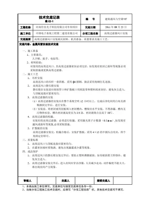
2、材料检验:
对使用的高效送风口,其高效过滤器密封必须完好,如发现有密封已损坏等现象必须采取措施或更换高效过滤器。
二、施工工艺
1、吊杆安装
高效送风口的吊杆一套四根,采用ф8圆钢,接法采用角钢打孔连接。
2、高效送风口静压箱安装
静压箱在安装前应将按管口和扩散板口用纸胶带和塑料纸密封好,避免灰尘进入,与顶板连接应紧密均匀。
5、扩散板的安装
高效过滤器安装完,检漏合格后,安装扩散板,采用4×15的半圆头自攻丝,四个角固定好即可。
三、质量标准
1、高效送风口与顶板连接应紧密均匀。
2、在灌密封液时要饱满,避免出现漏灌或少灌等现象。
四、成品保护
1、高效送风口的静压箱安装完毕后,要防止塑料薄膜破损,如有破损要立即修补,避免灰尘进入。
3、高效过滤器的安装
(1)高效过滤器的安装应在整个系统空吹12小时以上,完成后净化间用白布及酒精擦拭完毕后,进行安装。
(2)安装前,将密封液用刮板填入密封槽内,槽架应水平安装,不得渗漏,槽内无污物和水份,槽内密封液高度宜为2/3涂,密封液熔点宜高于50℃。
4、高效过滤器的检漏。
安装好的高效过滤器,必须进行检漏,采用激光离子计数器(0.5μm),如发现有漏风或损坏等现象,必须采取措施。
更换风口安全操作规程(3篇)
更换风口安全操作规程一、引言风口是指风机出风口,是风机系统的关键部分之一。
为了确保风口的安全运行,保护操作人员的安全,本规程旨在对风口的安全操作进行规范。
二、风口操作前的准备工作1. 检查风口及周边区域是否有杂物、障碍物,及时清理;2. 检查风口的密封性能,确保其正常工作;3. 检查相关的电气设备是否正常运行;4. 检查风口周边的安全标志和警示标志是否完好可见。
三、风口的开启操作1. 操作人员应戴好防护手套、安全帽等个人防护装备;2. 使用专门的工具扳动风口操作杆,确保手指与风口接触的时间最短,以避免受伤;3. 开启风口时,应站在安全的位置,确保不会被风口突然打开造成的风力冲击;4. 打开风口后,要观察风口是否完全开启,确保风机输出的气流畅通无阻。
四、风口的关闭操作1. 操作人员应站在安全的位置,确保不会被风口突然关闭造成的风力冲击;2. 使用专门的工具扳动风口操作杆,确保手指与风口接触的时间最短,以避免受伤;3. 关闭风口时,要观察风口是否完全关闭,以确保风机输出的气流得到有效控制;4. 关闭风口后,要及时锁紧,确保不会因外力而意外打开。
五、风口的维护保养1. 风口的密封性能应定期检查,如发现密封不良应及时更换密封件;2. 风口的润滑部件应定期加注润滑油,确保其正常运转;3. 风口的外部清洁应定期进行,确保其通风效果良好;4. 风口的安全标志和警示标志应定期检查,如损坏应及时更换。
六、风口安全注意事项1. 在操作风口时,禁止将手指、头部等部位伸入风口;2. 在操作风口时,禁止使用非专业工具进行操作;3. 在操作风口时,应确保自己的位置安全,避免被风力冲击;4. 在操作风口时,应注意周围环境的安全,避免意外事故的发生;5. 在维护保养风口时,应遵守相关的安全操作规程,确保自己的安全。
七、风口事故应急处理1. 一旦发生风口事故,应立即停止操作,确保自己的安全;2. 如有必要,应立即向相关部门报告事故,寻求支援和帮助;3. 在事故处理过程中,应遵循相关的应急处理程序,确保事故得到妥善处理;4. 事故处理完毕后,应进行事故调查和分析,总结经验教训,以避免类似事故再次发生。
药厂GMP车间液槽式高效送风口安装方法(图解)
药厂GMP车间液槽式高效送风口安装方法(图解)液槽式高效送风口和液槽式百级送风单元在我国的上世纪80~9O 年代就已开始技术吸收、开发和应用。
但由于种种原因,一直以来,没有得到全面推广。
而近年来,新版GMP在药品生产的核心区(如A级区、A+B区等),对空气净化的要求明显提高。
同时,这几年在液槽密封技术中,对新型框架结构的研制开发、对新型液槽密封胶(俗称果冻胶)的研制和改良,使得液槽式高效送风口的使用量大幅度提高。
逐步成为高等级洁净环境主流的密封方式。
液槽式高效送风口与普通高效送风口,其不同在于过滤器安装密封方式上。
见图1和图2。
为了使工程项目经理,工程安装人员(尤其是高效过滤器的安装人员)尽可能了解和熟悉此类风口和过滤器的特点,避免安装中由于不熟悉、不了解而造成实际上的泄漏发生,现列举一些要点供参考。
1 送风口和百级框安装中必须复查的内容送风口示意图参见图3,百级框型材参见图4、图5。
送风口箱体泄漏检查的主要部位有:(1)箱体外壳四周的焊缝区域,尤其是过滤器出风端箱体的拼缝部位。
必须是满焊或接缝内外打胶处理(我们曾发现焊缝漏水)。
(2)箱体内的密封刀口:四条边应平直(目测),而且刀面应基本处于同一个平面上(可用铝板、有机玻璃板或PVC板检查)。
(3)刀口与刀口相接的转角处:焊缝应连续并且经过打磨,不得有焊渣、突瘤、凹坑等出现。
液槽百级框泄漏检查的主要部位有:(1) 框架拼接部位(二通、三通和四通),接头处的密封是关键,也是难点。
(2) 框架整体平整度:首先对整体需要调节平整。
其次,经上人等受力后会导致接头处松动而框架变形,此时需要再次调整。
(3) 经调整后的框架,其所有接缝断面均需打胶密封(而不仅仅是过滤器的接触面)参见图6。
2 液槽过滤器复检一般来讲,高效过滤器在出厂前都已进行检漏测试,而且检测的重点放在过滤纸本身的质量和过滤纸与框架的密封质量。
但是由于液槽过滤器(参考)的结构方式比较特殊,有时会出现意想不到的情况而造成送风口检测时的泄漏现象。
盖伊空调产品安装与使用手册说明书
MODELS:3VIR09HP230V1B O 3VIR12HP230V1B O 3VIR18HP230V1B O 3VIR24HP230V1B O Thank you for choosing our product.Please read this Installation & Owner’s Manual carefully before operation and retain it for future reference.If you lose this Manual, please contact your local distributor orvisit /resources now to download andfile the electronic version. INSTALLATION MANUALSingle-Zone, Heat Pump SystemCONTENTSSafety precautions .......................................................................................1-4......................................................................................................5..........................................................................................6-7..............................................................................8-9............................................................................................. 10................................................................11-12Parts name Installation notice Installation of outdoor unit Test and operationConfiguration of connection pipe Limited Warranty Statement (13)iTable of Contents & Quick Tip Video QR C ode (i)Explanation of Symbols ........................................................................................i iExplanation of SymbolsWARNING CAUTION NOTICE1.Damage the product due to improper use or misuse of the product;2.Alter ing , chang ing , maintain ing or us ing the product with other equipment without following the recommendations in manufacturer's instruction manual;3.After verification, the product defect is directly caused by corrosive gas;4.After verification, the defects are due to improper operation or handling during the transportation of product;5.Operat ing , repair ing or maintain ing the unit without following the instruction manual or related regulations .6.After verification, the problem or dispute is caused by the quality orperformance of parts and components produced by other manufacturers;7.The damage is caused by natural disasters , a hazardous environment or force majeure.Exception ClausesManufacturer will bear no responsibilities when personal injury or property loss is caused by the following reasons.This symbol indicates the possibility of death or serious injury.This symbol indicates the possibility of injury or damage to property.Indicates important but not hazard-related information, used to indicate risk of property damage.If you need to install, move or maintain th is air conditioner, please use a licensed HVAC dealer to avoid serious damage or personal injury or death.When refrigerant leaks or requires discharg ing during installation, maintenance, or disassembly, it should be handled by certified professionals in compliance with local laws and regulations.This equipment is not intended for use by persons (including children) with reduced physical, sensory or mental capabilities or lack of experience and knowledge unless they have been given supervision or instruction concerning use of the equipment by a person responsible for their safety.Children should be supervised to ensure that they do not play with the equipment .Parts nameNOTE●Actual product may be different from above graphics, please refer to actual product.Installation notice7To ensure safety, please be mindful of the following precautions.12281339451410611Please contact the local agent for installation.Don’t use unqualified power cold.Tools for installationScrew driver Impact drillOpen-endPipe cutterwrench detector Leak Vacuum pump Level meterPressure meter Universal meter Measuring tapespanner Inner hexagon Drill headPipe expander ●●Torque wrench Safety precautions for installing and relocating the unitNOTICEInstallation of outdoor unitPlace the outdoor unit on the support.2.Fix the foot holes of outdoor unit with bolts.1.Remove the screw on the right handle of out-handleRemove the screw cap of valve and aim the pipe joint at the bellmouth of pipe.2.3.2.Step 1:Fix the support of outdoor unit(select it according to the actual inst-2.g r should be installed at least 8 in .)9000 -, 6 expansion screws are needed; for 24000~30000 8 expansion screws are needed; for the unit capacity of 36000+ Btu 10Step 4:Connect indoor and outdoor pipesscrewStep 2:Install drain joint(only for some models)1.Connect the outdoor drain joint into the hole on the chassis, as shown in the picture below. Connect the drain hose into the drain vent. allation situation)1.Select installation location according to Step 3:Fix outdoor unit1.Pretighten the union nut with hand.the house structure.Fix the support of outdoor unit on the sele- cted location with expansion screws.4. 2.1.2.Step 5:Connect outdoor electric wireAfter tighten the screw, pull the power cord slightly to check if it is firm.Never cut the power connection wire to prolong or shorten the distance.Step 6: Pipe NeatlyRemove the wire clip; connect the power con-nection wire and signal control wire (only for cooling and heating unit) to the wiring terminal according to the color; fix them with screws.Fix the power connection wire and signal con-trol wire with wire clip (only for cooling and h-eating unit). 1.Tighten the union nu t with torque wrench NOTICEreasonably and hidden possibly. Min. semidiam- eter of bending the pipe is 4 in .The pipes should be placed along the wall, bent If the outdoor unit is higher than the wall hole,you must set a U-shaped curve in the pipe before pipe goes into the room, in order to prevent rain from getting into the room.Test and operationLeak detection 1.2.With a leak detector:Check if there is a leak.With soap water:If leak detector is not available, please use soap y water for leak detection. Apply soap water at the suspected position and keep the soap water for more than 3min. If there are air bubbles coming out of this position, there's a leak.Check after installationTest operation1.●●Preparation of test operationThe client approves the air conditioner.Specify the important notes for air conditioner to the client.●●2.●Method of test operationn on o t t u bFFO/NOs s e r p,r ewo pe h t h g u o r h t t uPthe remote controller to start operation.Press MODE button to select AUTO, COOL, DRY , FAN and HEAT to check whether the operation is normal or not.If the ambient temperature is lower than 16°C(61°F), the air conditioner can’t start cooling.Pipe expanding methodA: Cut the pipeConfirm the pipe length according to the distance of indoor unit and outdoor unit.Cut the required pipe with pipe cutter.N OTICEImproper pipe expanding is the main cause of refriger-ant leaks . Please expand the pipe according to the following steps:Additional refrigerant charging amount for R410Aimproper expandingthe length is equalleaning damaged cracksurfaceC: Put on suitable insulating pipeunion pipepipe26.7/-(80/-)●uneventhicknessWorking temperature rangeMaximumcoolingDB/WB(°C /°F)26.7/19.4(80/67)50/24(122/75)Outdoor sideMaximumheatingNOTE●30/18(86/65)3VIR09HP230V1AO, 3VIR12HP230V1AO3VIR18HP230V1AO, 3VIR24HP230V1AOheating is -30°C(-22°F)~30°C(86°F).DB/WB(°C /°F)Indoor sideB: Remove the burrs●Remove the burrs with shaper and prevent theD: Put on the union nutpipe and outdoor valve;install the union nut onthe pipe.●E: Expand the port●Remove the union nut on the indoor connectionCheck the quality of expanding port. If there isF: Inspection●3VIR09HP115V1AO,3VIR12HP115V1AONOTEburrs from getting into the pipe.any blemish, expand the port again according tothe steps above.Contact your installing contractor. You may find the installer’s name on the equipment or in your Owner’s packet. Complete product registration below and keep on file for future reference. Warranty registration: Register your unit(s) on , follow links to "WarrantyU.S. CONTACT INFORMATION TRADEWINDS, LLCE-mail: ******************Contractor Support: 888-850-7928 | Mon-Fri 8 AM - 5 PM EDT。
管道风门安装技巧与流程
管道风门安装技巧与流程下载温馨提示:该文档是我店铺精心编制而成,希望大家下载以后,能够帮助大家解决实际的问题。
文档下载后可定制随意修改,请根据实际需要进行相应的调整和使用,谢谢!并且,本店铺为大家提供各种各样类型的实用资料,如教育随笔、日记赏析、句子摘抄、古诗大全、经典美文、话题作文、工作总结、词语解析、文案摘录、其他资料等等,如想了解不同资料格式和写法,敬请关注!Download tips: This document is carefully compiled by theeditor. I hope that after you download them,they can help yousolve practical problems. The document can be customized andmodified after downloading,please adjust and use it according toactual needs, thank you!In addition, our shop provides you with various types ofpractical materials,such as educational essays, diaryappreciation,sentence excerpts,ancient poems,classic articles,topic composition,work summary,word parsing,copy excerpts,other materials and so on,want to know different data formats andwriting methods,please pay attention!管道风门是一种用于控制管道内介质流量的装置,广泛应用于石油、化工、电力、冶金等行业。
风管机风口安装方法
风管机风口安装方法
风管机风口的安装是整个风管系统中非常重要的一个环节,它直接关系到风管
系统的正常运行和使用效果。
下面我们来详细介绍一下风管机风口的安装方法。
首先,在进行风口安装之前,我们需要准备好相应的工具和材料。
通常情况下,我们需要准备螺丝刀、螺丝批、螺丝、密封胶等工具和材料。
接下来,我们需要确定风口的安装位置。
在确定位置之前,我们需要根据实际
情况和设计要求,合理选择风口的安装位置,确保其能够满足系统的通风需求。
在确定好安装位置之后,我们可以开始进行风口的安装工作。
首先,我们需要
将风口放置在安装位置上,并使用螺丝将其固定在风管上。
在固定风口的过程中,我们需要确保螺丝拧紧,以免风口在使用过程中出现松动现象。
安装风口的过程中,我们还需要注意密封处理。
在固定好风口之后,我们需要
使用密封胶对风口周围进行密封处理,以防止风口与风管之间出现漏风现象,影响整个风管系统的使用效果。
最后,我们需要进行安装质量的检查。
在完成风口安装之后,我们需要对安装
质量进行检查,确保风口安装牢固,密封处理完好,没有出现任何安装质量问题。
总的来说,风管机风口的安装方法并不复杂,但是在实际操作中需要我们仔细、认真地进行操作,确保安装质量达到要求。
只有这样,才能保证整个风管系统的正常运行和使用效果。
希望以上内容能够对大家有所帮助。