MTN7143M-11A中文资料
华三渠道HSE培训教材1——WLAN产品

WA1208 支持RF最大输出功率500mW、支持多级功率可调, 支持RF最大输出功率500mW、支持多级功率可调,接收 RF最大输出功率500mW 灵敏度最高-97dBm, 灵敏度最高-97dBm,真正扩大覆盖范围 支持(隐含)ESSID、静态WEP&基于Tkip动态加密、 WEP&基于Tkip动态加密 支持(隐含)ESSID、静态WEP&基于Tkip动态加密、支持基于流 Qos、上行支持基于ESSID VLAN更好服务网络 Qos、上行支持基于ESSID的VLAN更好服务网络 ESSID的
WCB300g
支持Wi-Fi 接入保护 (WPA-PSK/WAP RADIUS) 接口( 电脑) 提供Cardbus 接口(笔记本 电脑)
无线网卡(二)
•兼容802.11a、802.11b、802.11g标准的PCI接 口卡 •支持WPA加密,128位AES加密和64位、128位 共享密钥WEP加密
目录
WLAN系列产品介绍 WLAN系列产品介绍 WLAN组网应用 WLAN组网应用
Table of Contents
华为3Com WLAN系列产品
标准型AP
AP7250/AP8250/AP8750 WA1208E-DG、WA1208E-AG WA1208 WA1208E-AGP
大功率AP
无线网桥
WB2010/2011专业网桥 楼对楼无线网桥(室内/室外)
11abg 无线PCI适配器、11abg 无线PC卡
PCI接口、PCMCIA接口
WCB500ag、WUB300g、WCB300g
PCMCIA接口、USB接口
华为3Com WLAN系列产品
WA1208E室外机箱 WA1208E室外机箱
MAV-11SM中文资料

ABSOLUTE MAXIMUM RATING7
DC POWER at Pin 3
THERMAL RESISTANCE 6
θ jc °C/W 115 105 115 100 120 120 140 110 100 110 95 85 125
CAPD DATA
(see RF/IF Designer Handbook)
2000 — 11.0 10.5 — 11.0 11.0 — — 10.0** 10.0** — 6.5** —
note 5 note 1 Typ. Output Input (1 dB (no Comp.) damage) MIN. 13.0 8.5 8.0 7.0 9.0 8.5 19.0 12.5 7.5 7.5 7.0 5.5 9.0 +1.5 +4.5 +10.0 +12.5 +2.0 +5.5 +12.5 +1.5 +4.5 +10.0 +11.5 +18.0 +17.5 +13 +13 +13 +13 +13 +13 +13 +13 +13 +13 +13 +20 +13
cb cb cb cb
3.0 +14.5 5.0 +19.0 3.3 +27.0 5.5 +14.0 6.5 +17.0 6.0 +23.0 7.0 +24.5 6.5 +29.0 3.6 +30.0
WW107 cb WW107 cb WW107 cb RRR137 cb ቤተ መጻሕፍቲ ባይዱRR137 cb RRR137 cb RRR137 cb RRR137 cb RRR137 cb
MTAN7146M-12A中文资料

Matrix Display 5.0" 5x8 Dot Matrix Display
FEATURES FEATURES
· 5.0" 5x8 dot matrix · Additional colors/materials available
OPTO-ELECTRICAL CHARACTERISTICS (Ta OPTO-ELECTRICAL CHARACTERISTICS (Ta = 25°C)
PART NO. PEAK WAVE LENGTH (nm) 567 635 635 660 567 635 635 660 FACE COLORS EMITTED COLOR
SURFACE COLOR EPOXY COLOR
MAXIMUM RATINGS
IF (mA) VR (V) PD (mW)
PINOUT 2
COLUMN CATHODE PIN NO. FUNCTION 1. 2. 3. 4. 5. 6. 7. 8. 9. 10. 11. 12. 13. 14. ANODE ROW 6 CATHODE COLUMN 1 ANODE ROW 8 ANODE ROW 5 CATHODE COLUMN 3 ANODE ROW 4 ANODE ROW 7 CATHODE COLUMN 4 CATHODE COLUMN 5 CATHODE COLUMN 3 CATHODE COLUMN 2 ANODE ROW 1 ANODE ROW 2 ANODE ROW 3
5 5 5 4 5 5 5 4
6800 7800 7800
10 10 10 20 10 10 10 20
1 1 1 1 2 2 2 2
Operating Temperature: -25~+85, Storage Temperature: -25~+100. Other face/epoxy colors are available.
伊玛产品类别

18~36 VDC
PNP NO/NC,NPN NO/NC
4~20 mA,0~10 V
可
PA1108
智慧型
7 LED
内螺纹
G 1/4
400 bar
四线
18~36 VDC
PNP NO/NC,NPN NO/NC
4~20 mA,0~10 V
可
PA1109
智慧型
7 LED
内螺纹
G 1/4
2 bar
四线
18~36 VDC
200
60
M12
接插件
N
Y
N
IP67
否
IA0031
齐平
brass
10~36VDC
1
两线
NO
DC PNP/NPN
200
60
M12
接插件
N
Y
N
IP67
否
IA0032
齐平
brass
10~36VDC
1
两线
NC
DC PNP/NPN
200
60
M12
接插件
N
Y
N
IP67
否
IA0033
非齐平
brass
10~36VDC
可
TA1099
智慧型
7 LED
内螺纹
M18 X 1.5
-40~150°C
四线
20~30 VDC
PNP NO/NC,NPN NO/NC
4~20 mA,0~10 V
可
产品类别
压力变送器(模拟量输出)
压力变送器(开关量输出)
订货号
功能
显示
牙口形式
MT1000A_1100A 产品交流手册(运营商版)

MT1100A
MT1100A
设备、系统的研发与生产
网络开通、安装和维护
主要应用与协议接口
13
主要应用与协议接口
• 固网和移动接入网络的安装、维护和故障处理
– 集所有功能于一体的测试工具 OTN (OTU1, OTU2, OTU1e/2e, OTU1f/2f, ODU0, ODUflex, OTU3, OTU3e1/3e2 和 OTU4)
安立传输仪表MT1X00A操作培训
OTN操作界面
浏览测试结果
34
Company Profile | ANRITSU CORPORATION Copyright© ANRITSU
安立传输仪表MT1X00A操作培训 OTN操作界面-按右边文本图符,进入文本存储界面。
35
Company Profile | ANRITSU CORPORATION Copyright© ANRITSU
10G OTN (BTS/NB)
OLT Ethernet Switch
Internet
TDM Transport
接入网
OLT
GE/10GbE (RNC/BSC)
11 Mobile Backhaul
Femtocell
GbE/10GbE FTTx, xDSL
ONU
在哪里使用?
1.5M to 100G 4 x 100G 400G
安立传输仪表MT1X00A操作培训
OTN操作界面
在测试页面选择测试标准
32
Company Profile | ANRITSU CORPORATION Copyright© ANRITSU
安立传输仪表MT1X00A操作培训 OTN操作界面-按右上角的测试键,开始自动测试。
211001a【通用网络模块使用...

211001a【通⽤⽹络模块使⽤...通⽤⽹络模块使⽤⼿册MTA211北京迈特安技术发展有限公司MasterSecurity Technology Development (Beijing) Ltd.感谢您选⽤北京迈特安技术发展有限公司的产品,希望我们先进的防盗报警系统会给您的⽣活、⼯作带来安全与⽅便!⽂件名称:通⽤⽹络模块使⽤⼿册⽂件号:211001a编写部门:北京迈特安技术发展有限公司硬件部⽬录1产品概述 (3)2主要功能及特点 (3)3安装与接线 (4)3.1接线描述 (4)3.1.1特制连接线接线部分 (4)3.1.2⽹络模块接⼝板连接部分 (5)3.1.3⽹络模块信号板连接部分 (5)3.2安装注意 (5)4运⾏指⽰ (6)5参数设置 (7)5.1主机编程设置 (7)5.1.1Vista120主机编程部分 (7)5.1.2Vista 20P主机编程部分 (8)5.1.3DS7400主机编程部分 (8)5.1.4DS7240主机编程部分 (9)5.1.5DSC 1832系列主机编程部分 (10)5.1.6DSC PC4020主机编程部分 (10)5.1.7Visonic POWERMAX+主机编程部分 (11)5.1.8Visonic Hunter-Pro 8144主机编程部分 (12)5.2⽹络模块参数设置 (12)5.2.1BOSCH DS7400特别设置内容 (12)5.2.2BOSCH DS7240特别设置内容 (13)5.2.3DSC 1832系列主机特别设置内容 (13)5.2.4DSC PC4020主机特别设置内容 (13)5.2.5Visonic POWERMAX+特别设置内容 (14)5.3⽹络模块设置⼯具使⽤ (14)5.4通⽤⽹络模块-23推荐上位机M ONITOR_XP软件参数设定166运⾏机制以及上报内容 (17)6.1运⾏机制 (17)6.2上报内容 (18)7恢复出⼚后的默认参数 (18)8产品规格 (19)8.1电⽓参数 (19)8.2其他指标 (19)9配件清单 (19)10《CID报告码列表》 (19)产品概述当今社会⽹络⾮常普及,通⽤⽹络模块通过有线⽹络传输,具有上报信息及时、延迟时间少、组装联⽹⽅便等优点,并且能够与电话线上报形成双保险,让我们的⽣活更安全。
DuplineSafe 安全中继输出模块说明说明书
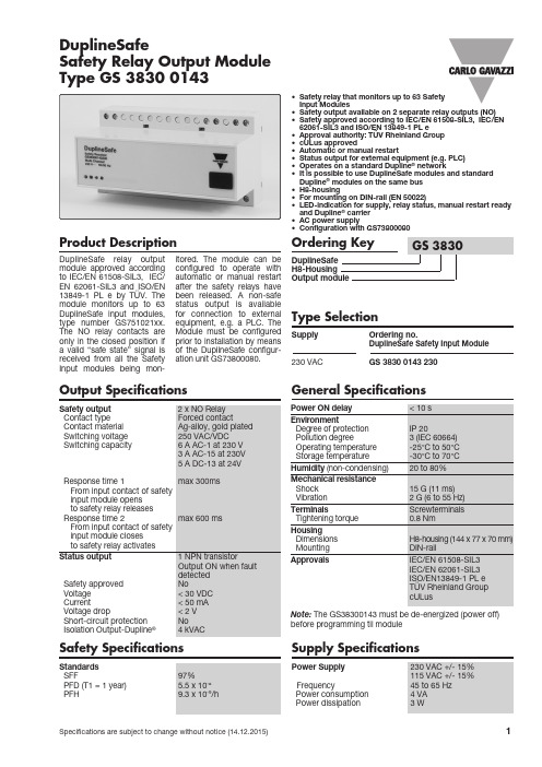
• Safety relay that monitors up to 63 Safety Input Modules• Safety output available on 2 separate relay outputs (NO)• Safety approved according to IEC/EN 61508-SIL3, IEC/EN 62061-SIL3 and ISO/EN 13849-1 PL e• Approval authority: TÜV Rheinland Group • cULus approved• Automatic or manual restart• Status output for external equipment (e.g. PLC)• Operates on a standard Dupline ® network• It is possible to use DuplineSafe modules and standard Dupline ® modules on the same bus • H8-housing• For mounting on DIN-rail (EN 50022)• LED-indication for supply, relay status, manual restart ready and Dupline ® carrier • AC power supply• Configuration with GS73800080Product DescriptionDuplineSafe relay output module approved according to IEC/EN 61508-SIL3, IEC/EN 62061-SIL3 and ISO/EN 13849-1 PL e by TÜV. The module monitors up to 63 DuplineSafe input modules, type number G S751021xx. The NO relay contacts are only in the closed position if a valid “safe state” signal is received from all the Safety Input modules being mon-itored. The module can be configured to operate with automatic or manual restart after the safety relays have been released. A non-safe status output is available for connection to external equipment, e.g. a PLC. The Module must be configured prior to installation by means of the DuplineSafe configur-ation unit GS73800080. Type SelectionSupply Ordering no.DuplineSafe Safety Input Module230 VACGS 3830 0143 230DuplineSafeSafety Relay Output ModuleType GS 3830 0143Safety SpecificationsStandards SFF97% PFD (T1 = 1 year)5.5 x 10⁻⁶ PFH9.3 x 10-9/hOutput SpecificationsNote: The GS38300143 must be de-energized (power off) before programming til moduleGeneral SpecificationsSupply SpecificationsPower Supply 230 VAC +/- 15%115 VAC +/- 15% Frequency45 to 65 Hz Power consumption 4 VA Power dissipation3 WWiring DiagramMode of OperationThe Safety Output module G S3******* monitors up to 63 Safety Input modules, type number G S751021xx. Each Safety Input module is monitoring the status of one potential-free contactin a safety device, e.g. anemergency stop palm but-ton or pull cord switch. The Safety Input modules arecontinuously transmitting on the Dupline ® bus the status of the safety contacts using a dynamic signaling princi-ple on two Dupline ® channel addresses (please refer to G S751021xx datasheet for more details). During configuration of theSafety Output module, theuser must define on whichDupline ® channel address-es Safety Input modules shall be monitored. If all themodules are sending avalid “safe-state” signal,then the relay contacts ofthe Safety Output modulewill be closed. In any other situation (non-safe signal received from one or moreSafety Input modules or bus fault), the relay contacts willbe open, thus keeping the system in a safe state. Find below a principle diagram of a DuplineSafe system.The Channel Generator Any type of Dupline ® Chan-nel G enerator can be used, as this component is not part of the safety function. However, it is important to note that all Dupline ® chan-nel addresses used for Safe-ty Input modules must be monostable. Split I/O mode and intelligent channel func-tions are not allowed. If this rule is not obeyed, the relay contacts of the Safety Out-put module will remain in the open position in any situa-tion.Combined SystemsIt is allowed to use stan-dard Dupline ® modules on the channel addresses not used for safety signals, thus allowing combined systems.Monitoring from a PLC, PC or Text DisplayThere are two products available for interfacing a DuplineSafe system to a PLC, PC, Text Display or Touchscreen. One possi-bility is the Profibus-DP gateway (G S3*******), the other possibility is the small Modbus inter-face G STI50 for Text dis-plays and Touchscreens. Using these products, it is possible to monitor theIndicatorsSupply OK Dupline ® OK Relay statusManual restart ready Configuration modeGS 3830 0143DuplineSafe Principle Diagram Input SpecificationsGS 3830 0143Mode of Operation (cont.)status of all the inputs of the Safety Input modules from e.g. a PLC or Text Display. It is not allowed to perform any control function on the channel addresses used for safety signals.Automatic or manual restart Two different operation modes for restart can be configured. A restart is needed whenever the Safety output has been brought to the safe state (relay con-tacts open). If “automatic restart” is selected then the Safety Output module will automatically close the relay contacts as soon as a valid “safe-state” signal is received from all the Safe-ty Input modules. If “manu-al restart” is selected, an activation of the “manu-al restart” input is required to make a restart, and the restart will only happen ifall Safety Input modules aresending a “safe-state” signal.Status outputThe status output is ONwhen a fault or a safetytransmitter is actuated. Thisoutput can be used as anindication by using a LEDor buzzer/horn to sound analarm.Synchronization ChannelThe synchronization channelis used by the Safety Relayto send out a synchroniz-ation signal to the SafetyInput modules on the bus.Therefore, all the SafetyInput modules and the Safe-ty Relay, which together areperforming a safety function,must be coded for the samesynchronization channel.But in case there is alreadyanother safety output mod-ule on the bus sending asynchronization signal onthis channel, then this signalcan be used by other safetyoutput modules.Configuration of the SafetyOutput modulePrior to installation, theSafety Output module needsto be configured by theDuplineSafe configurationunit G S7*******. The fol-lowing parameters need tobe selected:Number of channels on theDupline® busThe “number of channels”is actually selected on thechannel generator, but theRelay Output Module needto know this figure to ensurecorrect operation.Channel addresses of SafetyInput modules to be mon-itoredEach Safety Input Module isusing two channel address-es to send its signal. Thepossible selections are inthe range A3/A4 .. P7/P8.It must be defined whichchannel addresses the Safe-ty Output module shall mon-itor. (Please note that thechannel address A1/A2 isnot allowed in the system).Synchronization channelPlease refer to abovedescriptionPlease refer to the usermanual for the Dup-lineSafe Configuration UnitG S7******* for detailedinstructions on how to con-figure the Safety Outputmodule GS38300143 to per-form the desired function.DuplineSafe - System Characteristics and RulesReaction timeThe reaction time for the total Dupline® safety-loop depends of the num-ber of Dupline® channels. The response time can be calculated as:Reaction time on r elay r elease (wo r st-case): 2 x Number of Dupline® chan-nels + 40 [ms]Note: Reaction time is for the total Dupline® safe-ty-loop; from a safety input goes to non-safe state until the output relay is released. Reaction time on r elay acti-vate (wor st-case): 4 x Num-ber of Dupline® channels + 80 [ms]Note: Reaction time is for the total Dupline® safe-ty-loop; from a safety input goes to safe state until the output relay is activatedTopologyThe Dupline® system has free topology, so cable branches can freely be made at any point in the system. There are no specif-ic length restriction on cablebranches.Cable typesA non-shielded twisted paircable with a cross-sec-tion of 1.5 mm2 is recom-mended, but the Dup-line® bus can also run oncable without twistingand with lower cross-sections. However, the rulesmentioned below must beobeyed.Cabling rulesThe Dupline® system is anextremely robust transmis-sion system, but the followingrules should be obeyed:Rule no. 1The two Dupline® wires mustbe “floating” (none of thetwo wires may be connect-ed to any other potential).Specifically it should bemade sure that the Dupline®common is not connect-ed to protective earth, e.g.through the power supply.Rule no. 2If the longest cable pathexceeds 1.5 km a DT01 ter-mination unit needs to beinstalled at the point farthestaway from the channel gen-erator.If above rules are notobeyed, noise may beinduced in the system, andas a result the relay contactsof the safety output mod-ule will remain in the openposition.Distance, cable and num-ber of Safety input modulesIt is not always the full cap-acity of 63 Safety Inputmodules can be utilized. Itdepends on the cable typeand the length of the cable.The following rule applies:Total current x cable loopresistance < 3,7 VThe total current is the sum-marized current consump-tion of all Dupline®-poweredmodules on the bus. A SafetyInput module typ. uses 1mA.Cable loop esistance = 2x Length of cable (km) xresistance/km (for the cabletype used)Please note that the “lengthof cable” in this calculationis not necessarily the totallength of cable used, it is thecable path from the chan-nel generator to the farthestSafety Input module. In otherwords, only the longestcable path counts.If the above rule is notobeyed, the relay contactsof the Safety Output mod-ule will remain open in anysituation.Example: How many safe-ty Input modules can beinstalled on a 3 km of 1.5mm2 cable ?Cable loop resistance = 2 x3 km x 13,6 Ω/km = 81,6 ΩMax total current = 3,7 V /81,6 Ω = 45,3 mA.Conclusion: In this systemthe max capacity is 45 Safe-ty Input modules, since eachinput module uses 1 mA.DuplineSafe Safety ProcedureIn order to ensure correct safety function of a Dup-line®Safe system, the steps below need to be carried out:1.Identify the exact numberof Safety Input modulesrequired2.Make a table defining thechannel address of each Safety Input module (addresses to be selectedin the range A3/A4 ..P7/ P8)3. Physically allocate thenumber of Safety Inputmodules required andprogram them one by oneaccording to the addresstable, using the Dupline®-Safe Configuration unitGS73800080.4. Configure carefully theSafety Output module tomonitor exactly thechannel addressesselected for the Dupline®Input modules5. Connect all the SafetyInput modules and theSafety Output module tot h e D u p-line® two-wire busand bring all the inputs tothe safe state.6. Now the Safety RelayOutput should haveclosed the contacts. Ifthis is not the case,please review if theaddressing of the safetyinput modules and theconfiguration of the safe-ty output module complieswith each other. If thisdoes not solve theproblem, please checkthat all the DuplineSaferules have been obeyed.7. Now checkeach individualSafety Input module by:a.Remove the busconnection from SafetyInput module and checkthat the safety relayoutput releases.b. Re-connect the safetyinput module to the busand open the inputcontacts. Check that thesafety relay outputreleasesWhen all safety inputmodules have been checkedthis way, the DuplineSafesystem is ready to operate.GS 3830 0143。
MIMD10A中文资料

Test Condition IC = 50mA IC = 1mA IE = 50mA VCB = 50V VEB = 4V
IC/IB = 10mA / 1.0mA IC = 1mA, VCE = 5V
VCE = 10V, IE = -5mA, f = 100MHz
Ordering Information (Note 3)
Characteristic
Symbol VCC VIN IO
Value -50
-5 to +5 -500
Maximum Ratings NPN Section Tr2 @ TA = 25°C unless otherwise specified
Characteristic Collector-Base Voltage Collector-Emitter Voltage Emitter-Base Voltage Collector Current
Device MIMD10A-7
Packaging SOT-363
Shipping 3000/Tape & Reel
Notes: 3. For Packaging Details, go to our website at /datasheets/ap02007.pdf. 4. For Lead Free/RoHS Compliant version part number, please add "-F" suffix to the part number above. Example: MIMD10-A-7-F.
fT
Min Typ Max Unit
Test Condition
-0.3
¾
- 1、下载文档前请自行甄别文档内容的完整性,平台不提供额外的编辑、内容补充、找答案等附加服务。
- 2、"仅部分预览"的文档,不可在线预览部分如存在完整性等问题,可反馈申请退款(可完整预览的文档不适用该条件!)。
- 3、如文档侵犯您的权益,请联系客服反馈,我们会尽快为您处理(人工客服工作时间:9:00-18:30)。
MAXIMUM RATINGS
IF (mA) VR (V) PD (mW)
OPTO-ELECTRICAL CHARACTERISTICS
VF(V) typ. max. @mA IR(µA) max. @VR IV(µcd) typ. per seg. @mA
Grey Grey Red Grey Grey Grey Red Grey
White White Red White White White Red White
30 30 30 30 30 30 30 30
5 5 5 4 5 5 5 4
85 85 85 70 85 85 85 70
2.1 2.1 2.1 1.7 2.1 2.1 2.1 1.7
1. ALL DIMENSIONS ARE IN mm, TOLERANCE IS ±0.25mm UNLESS OTHERWISE SPECIFIED. 2. THE SLOPE ANGLE OF ANY PIN MAY BE ±5.0° MAX.
marktech optoelectronics
For up-to-date product info visit our web site at
1 1 1 1 2 2 2 2
Operating Temperature: -25~+85, Storage Temperature: -25~+100. Other face/epoxy colors are available.
CKAGE PACKAGE DIMENSIONS AND PIN FUNCTIONS
PINOUT
MTN2143-AG MTN4143-AO MTN4143-AHR MTN7143M-11A MTN2143-CG MTN4143-CO MTN4143-CHR MTN7143M-11C
Green Orange Hi-Eff Red Ultra Red Green Orange Hi-Eff Red Ultra Red
OPTO-ELECTRICAL CHARACTERISTICS (Ta OPTO-ELECTRICAL CHARACTERISTICS (Ta = 25°C)
PART NO. PEAK WAVE LENGTH (nm) 567 635 635 660 567 635 635 660 FACE COLORS EMITTED COLOR
3.0 3.0 3.0 2.2 3.0 3.0 3.0 2.2
20 20 20 20 20 20 20 20
100 100 100 100 100 100 100 100
5 5 5 4 5 5 5 4
2900 3300 3300 17300 2900 3300 3300 17300
10 10 10 20 10 10 10 20
元器件交易网
Single Display 0.43"URES
· 0.43" digit height · Left and right hand decimal point · Additional colors/materials available
120 Broadway • Menands, New York 12204 Toll Free: (800) 98-4LEDS • Fax: (518) 432-7454
All specifications subject to change.
414
PINOUT 2
COMMON CATHODE PIN NO. FUNCTION 1. 2. 3. 4. 5. 6. 7. 8. 9. 10. 11. 12. 13. 14. ANODE A ANODE F COMMON CATHODE NO PIN NO PIN ANODE LHDP ANODE E ANODE D ANODE RHDP ANODE C ANODE G NO PIN ANODE B COMMON CATHODE
PINOUT 1
COMMON ANODE PIN NO. FUNCTION 1. 2. 3. 4. 5. 6. 7. 8. 9. 10. 11. 12. 13. 14. CATHODE A CATHODE F COMMON ANODE NO PIN NO PIN CATHODE LHDP CATHODE E CATHODE D CATHODE RHDP CATHODE C CATHODE G NO PIN CATHODE B COMMON ANODE