塑封接收头LF1638B规格书
EM9636BBD产品说明书
EM9636B/BD产品说明书图1声明:此说明书归北京中泰研创科技有限公司所有。
未经本公司授权,任何公司及个人不得以盈利目的进行复制、抄袭、翻译或传播。
订购产品前,请详细了解产品性能是否符合用户需求。
说明书描述了产品的基本功能,若客户有特殊要求需要增加其他功能,请与本公司工程师联系。
说明书的内容力求准确、可靠。
本公司对侵权使用说明书所造成的后果不承担任何法律责任。
安全使用常识:•使用前请务必仔细阅读产品说明书。
•禁止带电插拔,以免瞬间冲击电压过大烧毁敏感元器件。
•避免频繁开机,以免对产品造成损坏。
目录第一章产品介绍 (3)1.1 概述 (3)1.2 特点 (3)1.3 一般特性 (5)第二章安装说明 (6)2.1 初始检查 (6)2.2 跳线分布图 (6)2.3 跳线设置 (6)2.3.1 模拟输入量程跳线说明 (7)2.3.2 模拟输入单端/差分方式跳线说明 (7)2.3.3 模拟输入电压/电流方式跳线说明 (7)2.3.4 模拟输出跳线说明 (8)2.3.5 模拟输出上电状态跳线说明 (8)2.3.6 加载默认网络设置跳线说明 (8)2.3.7 写保护跳线说明 (9)2.4 设备的安装 (9)2.4.1 使用网络接口时硬件安装 (9)2.4.2 使用网络接口时软件安装 (9)2.4.3 使用USB接口时硬件安装 (10)2.4.4 使用USB接口时软件安装 (10)2.4.5 设置更改模块参数设置 (10)第三章连接与测试 (13)3.1 管脚分布图 (13)3.1.1管脚功能定义说明 (13)3.2 模拟输入连接 (14)3.2.1 模拟信号种类 (14)3.2.2 单端模拟输入连接 (15)3.2.3 差分模拟输入连接 (15)3.3 模拟输出连接 (17)3.3.1 电压模拟输出连接 (17)3.3.2 电流模拟输出连接 (17)3.4 计数器输入连接 (18)3.5 数字量输入连接及注意事项 (18)3.6 数字量输出的连接 (19)3.7 编码器输入的连接 (20)3.8 PWM输出的连接 (21)3.9 SD卡的连接 (21)3.10 外触发与外时钟的连接 (21)3.11 测试 (21)3.8.1 模拟输入功能测试 (23)3.8.2 模拟输出功能测试 (24)3.8.3 计数器功能测试 (25)3.8.4 频率输入功能测试 (26)3.8.5 数字量输入功能测试 (27)3.8.6 数字量输出功能测试 (29)第四章原理说明 (31)4.1数据采集触发方式详解 (31)4.1.1采样时钟 (32)4.1.2采样方式 (32)4.1.3 触发信号 (32)4.1.4 边沿触发 (32)4.1.5 电平触发 (33)4.2 指示灯功能详解 (35)4.2.1 红灯,电源指示灯 (35)4.2.2 绿灯,采集指示灯 (35)4.2.3 黄灯,离线采集指示灯 (35)4.3 PWM脉冲生成 (36)第五章结构说明 (36)5.1结构图(尺寸图) (36)附录:....................................................................................................................................................... 错误!未定义书签。
大唐电信产品综合布线产品技术规格书.doc
大唐电信综合布线系统产品技术规格书1、增强型六类布线系统器件技术参数 (6)增强型六类屏蔽数字电缆. (6)增强型六类免打模块 (6)增强型六类屏蔽配线架. (6)增强型六类屏蔽跳线 (6)2、六类布线系统器件技术参数 (7)六类非屏蔽布线系统 (7)6 类非屏蔽双绞线 (7)6 类非屏蔽数据模块 (7)6 类 24 口非屏蔽配线架 (8)6 类非屏蔽跳线 (8)6 类水晶头 (8)六类屏蔽布线系统 . (9)六类屏蔽数字电缆 (9)六类屏蔽模块 (9)六类锌铸造屏蔽免打模块. (9)六类屏蔽配线架 (9)六类屏蔽跳线 .10 3、超五类布线系统器件技术参数. (10)超五类非屏蔽布线系统. (10)超五类非屏蔽双绞线 .10超五类 24 口非屏蔽配线架 .10超五类非屏蔽模块 .11超五类非屏蔽跳线 .11超五类 8C水晶头 .11 超五类屏蔽布线系统 (11)超五类屏蔽数字电缆 .11超五类屏蔽配线架 .12超五类屏蔽模块 .12超五类屏蔽跳线 .12超五类屏蔽水晶头 .13超五类室外架空电缆 .13超五类室外阻水电缆 .134、语音布线系统器件技术参数 (13)1 对 3 类电话线132 对3 类电话线14语音电话模块 .14电话水晶头 .143 类大对数数字电缆14室外 3 类 100 对大对数 .155 类大对数数字电缆15室外 3 类大对数数字电缆 .151-4 对语音跳线( 110-Rj45 )15110 型机架式 100 对跳线架15110 型连接模块165、铜缆配件技术参数 . (16)86 型斜面型单口、双口墙面板1686 型平面型单口、双口墙面板16RJ45 模块式 24 口空配线架1686 地插171U 铝制理线架176、机柜 (17)网络机柜 .17服务器机柜 .177、光纤光缆技术参数 . (19)光纤传输性能 . (19)光纤的光学传输性能满足相关标准要求.19A1a\A1b 型多模光纤( 50/125 、125)19D 型单模光纤19型单模光纤 .19 室内光缆 (20)室内千兆多模光缆( OM1) .20室内千兆多模光缆( OM2) .20室内万兆多模光缆( OM3) .20 单模室内光缆().21室外光缆 (22)室外中心管式多模光缆(GYXTW OM1、OM2) .22室外层绞式铝铠装多模光缆(GYTA OM1、OM2) .22室外中心管式单模( B1)光缆( GYXTW B1) .22 室外层绞式铝铠装单模光缆(GYTA B1) .22室外层绞式钢铠装单模光缆(GYTS B1) .23室外直埋单模光缆( GYTA53 B1) .23防蚁直埋光缆 (GYTA54) .24防蚁加强型直埋光缆 (GYTA34).248、光配线产品 (24)光纤跳线尾纤 . (24)SC型单模跳线尾纤24SC型多模跳线尾纤24LC 型单模跳线尾纤24LC 型多模跳线尾纤24ST 型单模跳线尾纤25ST 型多模跳线尾纤25 适配器 ( 法兰盘、耦合器 ) . (25)SC( FC、ST、LC)多模适配器 .25SC( FC、ST、LC)单模适配器 .25 光纤终端盒 (25)机架式光纤终端盒(配线架).26ODF光纤配线架26 光缆接头盒 (26)光缆接头盒 .269 安防线缆 (26)实芯聚乙烯绝缘射频电缆(SYV) .26物理发泡聚乙烯绝缘同轴电缆(SYWV) .27聚氯乙烯绝缘电缆( RVV、RVVP、RV、 RVS、RVB) .28 附件:产品图片 . (28)1、增强型六类布线系统器件技术参数增强型六类屏蔽数字电缆产品标准: ISO_IEC11801-A1-2008 、 TIA/EIA-568 、 10GBASE-T、YD/T 和 YD/T1019-2013产品特性:传输带宽≥500MHz,满足 10G 兆数据传输;铝箔结构,外径小,重量轻;排流线为圆型镀锡铜线;铜芯材料采用优质实芯裸铜导体,线芯直径≥,满足线规23AWG;绝缘材料采用优质高密度聚乙烯(HDPE),护套材料采用优质PVC料厚度为,防火级别为CM,铜缆外径为:¢±。
MX28F160C3T资料

MX28F160C3T/B16M-BIT [1M x16] CMOS SINGLE VOLTAGE3V ONLY FLASH MEMORY- Word write suspend to read- Sector erase suspend to word write- Sector erase suspend to read register report•Automatic sector erase, word write and sector lock/unlock configuration •Status Reply- Detection of program and erase operation comple-tion.- Command User Interface (CUI)- Status Register (SR)•Data Protection Performance- Include boot sectors and parameter and main sectors to be locked/unlocked•100,000 minimum erase/program cycles •Common Flash Interface (CFI)•128-bit Protection Register- 64-bit Unique Device Identifier - 64-bit User-Programmable•Latch-up protected to 100mA from -1V to VCC+1V •Package type:- 48-pin TSOP (12mm x 20mm)- 48-ball CSP (8mm x 6mm)FEATURES•Bit Organization: 1,048,576 x 16•Single power supply operation- VCC=VCCQ=2.7~3.6V for read, erase and program operation- VPP=12V for fast production programming - Operating temperature:-40°C~85°C •Fast access time : 70/90/110ns •Low power consumption- 9mA typical active read current, f=5MHz- 18mA typical program current (VPP=1.65~3.6V)- 21mA typical erase current (VPP=1.65~3.6V)- 7uA typical standby current under power saving mode•Sector architecture- Sector structure : 4Kword x 2 (boot sectors), 4Kword x 6 (parameter sectors), 32Kword x 31 (main sectors)- Top/Bottom Boot•Auto Erase and Auto Program- Automatically program and verify data at specified address- Auto sector erase at specified sector •Automatic Suspend EnhanceGENERAL DESCRIPTIONThe MX28F160C3T/B is a 16-mega bit Flash memory organized as 1M words of 16 bits. The 1M word of data is arranged in eight 4Kword boot and parameter sectors,and thirty-one 32K word main sectors which are indi-vidually erasable. MXIC's Flash memories offer the most cost-effective and reliable read/write non-volatile random access memory. The MX28F160C3T/B is packaged in 48-pin TSOP and 48-ball CSP . It is designed to be re-programmed and erased in system or in standard EPROM programmers.fast as 70ns, allowing operation of high-speed micropro-cessors without wait states.MXIC's Flash memories augment EPROM functionality with in-circuit electrical erasure and programming. The MX28F160C3T/B uses a command register to manage this functionality. The command register allows for 100%TTL level control inputs and fixed power supply levels during erase and programming, while maintaining maxi-mum EPROM compatibility.MXIC Flash technology reliably stores memory contents even after 100,000 erase and program cycles. The MXICMX28F160C3T/Bmechanisms. In addition, the combination of advanced tunnel oxide processing and low internal electric fields for erase and program operations produces reliable cy-cling. The MX28F160C3T/B uses a 2.7V~3.6V VCC sup-ply to perform the High Reliability Erase and auto Pro-gram/Erase algorithms.The highest degree of latch-up protection is achieved with MXIC's proprietary non-epi process. Latch-up pro-tection is proved for stresses up to 100 milliamps on address and data pin from -1V to VCC + 1V.The dedicated VPP pin gives complete data protection when VPP< VPPLK.A Command User Interface (CUI) serves as the inter-face between the system processor and internal opera-tion of the device. A valid command sequence written to the CUI initiates device automation. An internal Write State Machine (WSM) automatically executes the algo-rithms and timings necessary for erase, word write and sector lock/unlock configuration operations.A sector erase operation erases one of the device's 32K-word sectors typically within 1.0s, 4K-word sectors typi-cally within 0.5s independent of other sectors. Each sec-tor can be independently erased minimum 100,000 times. Sector erase suspend mode allows system software to suspend sector erase to read or write data from any other sector.Writing memory data is performed in word increments of the device's 32K-word sectors typically within 0.8s and 4K-word sectors typically within 0.1s. Word program sus-pend mode enables the system to read data or execute code from any other memory array location.MX28F160C3T/B features with individual sectors lock-ing by using a combination of bits thirty-nine sector lock-bits and WP, to lock and unlock sectors.The status register indicates when the WSM's sector erase, word program or lock configuration operation is done.The access time is 70/90/110ns (tELQV) over the oper-ating temperature range (-40°C to +85°C) and VCC sup-ply voltage range of 2.7V~3.6V.MX28F160C3T/B's power saving mode feature substan-tially reduces active current when the device is in static mode (addresses not switching). In this mode, the typi-cal ICCS current is 7uA (CMOS) at 3.0V VCC.As CE and RP are at VCC, ICC CMOS standby mode is enabled. When RP is at GND, the reset mode is enabled which minimize power consumption and provide data write protection.A reset time (tPHQV) is required from RP switching high until outputs are valid. Similarly, the device has a wake time (tPHEL) from RP-high until writes to the CUI are recognized. With RP at GND, the WSM is reset and the status register is cleared.MX28F160C3T/BMX28F160C3T/BMX28F160C3T/BTable 1. Pin DescriptionSymbol Type Description and FunctionA0-A19input Address inputs for memory address. Data pin float to high-impedance when the chip isdeselected or outputs are disable. Addresses are internally latched during a write orerase cycle.DQ0-DQ15input/output Data inputs/outputs: Inputs array data on the second CE and WE cycle during a pro-gram command. Data is internally latched. Outputs array and configuration data. Thedata pin float to tri-state when the chip is de-selected.CE input Chip Enable : Activates the device's control logic, input buffers, and sense amplifiers.CE high de-selects the memory device and reduce power consumption to standbylevel. CE is active low.RP input Reset/Deep Power Down: when RP=VIL, the device is in reset/deep power down mode,which drives the outputs to High Z, resets the WSM and minimizes current level.When RP=VIH, the device is normal operation. When RP transitions from VIL to VIH,the device defaults to the read array mode.WE input Write Enable: to control write to CUI and array sector. WE=VIL becomes active. Thedata and addresses are latched on the rising edge of the second WE pulse.VPP input/supply Program/Erase Power Supply:(1.65V~3.6V or 11.4V~12.6V)Lower VPP<VPPLK, to protect any contents against Program and Erase Command.Set VPP=VCC for in-system Read, Program and Erase Operation.Raise VPP to 12V±5% for faster program and erase in a production environment.OE input Output enable: gates the device's outputs during a real cycle.WP input Write Protect: When WP is VIL, the sectors marked Lock Down can't be unlockedthrough software. When WP is VIH, the lock down mechanism is disable and sectorspreviously locked down are now locked and can be unlocked and locked through soft-ware. After WP goes low, any sectors previously marked lock down revert to that state. VCC supply Device power supply: (2.7V~3.6V).VCCQ input I/O Power Supply: supplies for input/output buffers. (VCCQ must be tied to VCC) GND supply Ground voltage: all the GND pin shall not be connected.MX28F160C3T/BSECTOR STRUCTURE (TOP)Sector Sector Size Address Range (h)Boot Sector 04K Word FF000 ~ FFFFFBoot Sector 14K Word FE000 ~ FEFFFParameter Sector 04K Word FD000 ~ FDFFFParameter Sector 14K Word FC000 ~ FCFFFParameter Sector 24K Word FB000 ~ FBFFFParameter Sector 34K Word FA000 ~ FAFFFParameter Sector 44K Word F9000 ~ F9FFFParameter Sector 54K Word F8000 ~ F8FFFMain Sector 032K Word F0000 ~ F7FFFMain Sector 132K Word E8000 ~ EFFFFMain Sector 232K Word E0000 ~ E7FFFMain Sector 332K Word D8000 ~ DFFFFMain Sector 432K Word D0000 ~ D7FFFMain Sector 532K Word C8000 ~ CFFFFMain Sector 632K Word C0000 ~ C7FFFMain Sector 732K Word B8000 ~ BFFFFMain Sector 832K Word B0000 ~ B7FFFMain Sector 932K Word A8000 ~ AFFFFMain Sector 1032K Word A0000 ~ A7FFFMain Sector 1132K Word98000 ~ 9FFFFMain Sector 1232K Word90000 ~ 97FFFMain Sector 1332K Word88000 ~ 8FFFFMain Sector 1432K Word80000 ~ 87FFFMain Sector 1532K Word78000 ~ 7FFFFMain Sector 1632K Word70000 ~ 77FFFMain Sector 1732K Word68000 ~ 6FFFFMain Sector 1832K Word60000 ~ 67FFFMain Sector 1932K Word58000 ~ 5FFFFMain Sector 2032K Word50000 ~ 57FFFMain Sector 2132K Word48000 ~ 4FFFFMain Sector 2232K Word40000 ~ 47FFFMain Sector 2332K Word38000 ~ 3FFFFMain Sector 2432K Word30000 ~ 37FFFMain Sector 2532K Word28000 ~ 2FFFFMain Sector 2632K Word20000 ~ 27FFFMain Sector 2732K Word18000 ~ 1FFFFMain Sector 2832K Word10000 ~ 17FFFMain Sector 2932K Word08000 ~ 0FFFFMX28F160C3T/BSECTOR STRUCTURE (BOTTOM)Sector Sector Size Address Range (h)Boot Sector 04K Word00000 ~ 00FFFBoot Sector 14K Word01000 ~ 01FFFParameter Sector 04K Word02000 ~ 02FFFParameter Sector 14K Word03000 ~ 03FFFParameter Sector 24K Word04000 ~ 04FFFParameter Sector 34K Word05000 ~ 05FFFParameter Sector 44K Word06000 ~ 06FFFParameter Sector 54K Word07000 ~ 07FFFMain Sector 032K Word08000 ~ 0FFFFMain Sector 132K Word10000 ~ 17FFFMain Sector 232K Word18000 ~ 1FFFFMain Sector 332K Word20000 ~ 27FFFMain Sector 432K Word28000 ~ 2FFFFMain Sector 532K Word30000 ~ 37FFFMain Sector 632K Word38000 ~ 3FFFFMain Sector 732K Word40000 ~ 47FFFMain Sector 832K Word48000 ~ 4FFFFMain Sector 932K Word50000 ~ 57FFFMain Sector 1032K Word58000 ~ 5FFFFMain Sector 1132K Word60000 ~ 67FFFMain Sector 1232K Word68000 ~ 6FFFFMain Sector 1332K Word70000 ~ 77FFFMain Sector 1432K Word78000 ~ 7FFFFMain Sector 1532K Word80000 ~ 87FFFMain Sector 1632K Word88000 ~ 8FFFFMain Sector 1732K Word90000 ~ 97FFFMain Sector 1832K Word98000 ~ 9FFFFMain Sector 1932K Word A0000 ~ A7FFFMain Sector 2032K Word A8000 ~ AFFFFMain Sector 2132K Word B0000 ~ B7FFFMain Sector 2232K Word B8000 ~ BFFFFMain Sector 2332K Word C0000 ~ C7FFFMain Sector 2432K Word C8000 ~ CFFFFMain Sector 2532K Word D0000 ~ D7FFFMain Sector 2632K Word D8000 ~ DFFFFMain Sector 2732K Word E0000 ~ E7FFFMain Sector 2832K Word E8000 ~ EFFFFMain Sector 2932K Word F0000 ~ F7FFFMX28F160C3T/B2 PRINCIPLES OF OPERATIONThe product includes an on-chip WSM to manage sec-tor erase, word write and lock-bit configuration functions.After initial device power-up or return from reset mode (see section on Bus Operations), the device defaults to read array mode. Manipulation of external memory con-trol pins allow array read, standby and output disable operations.Status register and identifier codes can be accessed through the CUI independent of the VPP voltage. All functions associated with altering memory contents -sector erase, word write, sector lock/unlock, status and identifier codes - are accessed via the CUI and verified through the status register.Commands are written using standard microprocessor write timings. The CUI contents serve as input to the WSM, which controls the sector erase, word write and sector lock/unlock. The internal algorithms are regulated by the WSM, including pulse repetition, internal verifica-tion and margining of data. Addresses and data are in-ternally latched during write cycles. Address is latched at falling edge of CE and data latched at rising edge of WE. Writing the appropriate command outputs array data, accesses the identifier codes or outputs status register data.Interface software that initiates and polls progress of sector erase, word write and sector lock/unlock can be stored in any sector. This code is copied to and executed from system RAM during flash memory updates. After successful completion, reads are again possible via the Read Array command. Sector erase suspend allows system software to suspend a sector erase to read/write data from/to sectors other than that which is suspend. Word write suspend allows system software to suspend a word write to read data from any other flash memory array location.With the mechanism of sector lock, memory contents cannot be altered due to noise or unwanted operation. When RP=VIH and VCC<VLKO (lockout voltage), any data write alteration can be failure. During read opera-tion, if write VPP voltage is below VPPLK, then hard-ware level data protection is achieved. With CUI's two-step command sequence sector erase, word write or sector lock/unlock, software level data protection is 3 BUS OPERATIONThe local CPU reads and writes flash memory in-sys-tem. All bus cycles to or from the flash memory conform to standard microprocessor bus cycles.3.1 ReadInformation can be read from any sector, configuration codes or status register independent of the VPP volt-age. RP can be at VIH.The first task is to write the appropriate read mode com-mand (Read Array, Read Configuration, Read Query or Read Status Register) to the CUI. Upon initial device power-up or after exit from reset, the device automati-cally resets to read array mode. In order to read data, control pins set for CE, OE, WE, RP and WP must be driven to active. CE and OE must be active to obtain data at the outputs. CE is the device selection control. OE is the data output (DQ0-DQ15) control and active drives the selected memory data onto the I/O bus, WE must be VIH, RP must be VIH, WP must be at VIL or VIH.3.2 Output DisableWith OE at a logic-high level (VIH), the device outputs are disabled. Output pins (DQ0-DQ15) are placed in a high-impedance state.3.3 StandbyCE at a logic-high level (VIH) places the device in standby mode which substantially reduces device power consumption. DQ0~DQ15 outputs are placed in a high-impedance state independent of OE. If deselected dur-ing sector erase, word write or sector lock/unlock, the device continues functioning, and consuming active power until the operation completes.3.4 ResetAs RP=VIL, it initiates the reset mode. The device en-ters reset/deep power down mode. However, the data stored in the memory has to be sustained at least 100nsMX28F160C3T/Band output high impedance state.In read modes, RP-low deselects the memory, places output drivers in a high-impedance state and turns off all internal circuits. RP must be held low for a minimum of 100ns. Time tPHQV is required after return from reset mode until initial memory access outputs are valid. Af-ter this wake-up interval tPHEL or tPHWL, normal op-eration is restored. The CUI is reset to read array mode and status register is set to 80H. Sector lock bit is set at lock status.During sector erase, word write or sector lock/unlock modes, RP-low will abort the operation. Memory con-tents being altered are no longer valid; the data may be partially erased or written.In addition, CUI will go into either array read mode or erase/write interrupted mode. When power is up and the device reset subsequently, it is necessary to read sta-tus register in order to assure the status of the device. Recognizing status register (SR.7~0) will assure if the device goes back to normal reset and enters array read mode.3.5 Read Configuration CodesThe read configuration codes operation outputs the manu-facturer code, device code, sector lock configuration codes, and the protection register. Using the manufac-turer and device codes, the system CPU can automati-cally match the device with its proper algorithms. The sector lock codes identify locked and unlocked sectors.3.6 WriteWriting commands to the CUI enable reading of device data and identifier codes. They also control inspection and clearing of the status register. When VCC=2.7V-3.6V and VPP within VPP1 or VPP2 range, the CUI addition-ally controls sector erase, word write and sector lock/ unlock.The Sector Erase command requires appropriate com-mand data and an address within the sector to be erased. The Full Chip Erase command requires appropriate com-mand data and an address within the device. The Word Write command requires the command and address of mands require the command and address within the de-vice or sector within the device (Sector Lock) to be locked. The Clear Sector Lock-Bits command requires the command and address within the device.The CUI does not occupy an addressable memory loca-tion. It is written when WE and CE are active (whichever goes high first). The address and data needed to ex-ecute a command are latched on the rising edge of WE or CE. Standard microprocessor write timings are used.MX28F160C3T/B4 COMMAND DEFINITIONSThe flash memory has four read modes: read array, readconfiguration, read status, read query, and two writemodes: program, erase. These read modes are acces-sible independent of the VPP voltage. But write modesare disable during VPP<VPPLK. Placing VPP on VPP1/2 enables successful sector erase, word write and sec-tor lock/unlock.Device operations are selected by writing specific com-mands into the CUI. T able 3 defines these commands.Table 2. Bus OperationMode Notes RP CE OE WE DQ0~DQ15Read1,2VIH VIL VIL VIH DOUTOutput Disable2VIH VIL VIH VIH High ZStandby2VIH VIH X X High ZReset2VIL X X X High ZWrite2,3,4,5VIH VIL VIH VIL DINNotes:1.Refer to DC Characteristics for VPPLK, VPP1, VPP2 voltage.2.X can be VIL or VIH for pin and addresses.3.RP at GND±0.2 to ensure the lowest power consumption.4.Refer to Table 3 for valid DIN during a write operation.5.To program or erase the lockable sectors holds WP at VIH.MX28F160C3T/BTable 3. Command Definition (1)Command Bus Notes First Bus Cycle Second Bus CycleCycles Operation Address Data Operation Address DataRequired(1)(2)(3)(1)(2)(3) Read Array1Write X FFHRead Configuration> 22,4Write X90H Read IA ID Read Query22,7Write X98H Read QA QD Read Status Register23Write X70H Read X SRD Clear Status Register13Write X50HSector Erase/Confirm2Write X20H Write SA D0H Word Write22,5Write X40H/10H Write WA WD Program/Erase Suspend1Write X B0HProgram/Erase Resume1Write X D0HSector Lock2Write X60H Write SA01H Sector Unlock26Write X60H Write SA D0H Lock-Down Sector2Write X60H Write SA2FH Protection Program2Write X C0H Write P A PDNotes:1.Bus operation are defined in Table 2 and referred to AC Timing Waveform.2.X=Any address within device.IA=ID-Code Address (refer to Table 4).ID=Data read from identifier code.SA=Sector Address within the sector being erased.WA=Address of memory location to be written.WD=Data to be written at location WA.PA=Program Address, PD=Program DataQA=Query Address, QD=Query Data.3.Data is latched from the rising edge of WE or CE (whichever goes high first)SRD=Data read from status register, see T able 6 for description of the status register bits.4.Following the Read Configuration codes command, read operation access manufacturer, device codes, sectorlock/unlock codes, see chapter 4.2.5.Either 40H or 10H command is recognized by the WSM as word write setup.6.The sector unlock operation simultaneously clear all sector lock.7.Read Query Command is read for CFI query information.MX28F160C3T/B4.1 Read Array CommandUpon initial device power-up and after exit from reset mode, the device defaults to read array mode. This op-eration is also initiated by writing the Read Array com-mand. The device remains enabled for reads until an-other command is written. Once the internal WSM has started a sector erase, word write or sector lock con-figuration the device will not recognize the Read Array command until the WSM completes its operation unless the WSM is suspended via a Sector Erase Suspend or Word Write Suspend command. If RP=VIL device is in read Read Array command mode, this read operation no longer requires VPP . The Read Array command func-tions independently of the VPP voltage and RP can be VIH.4.2 Read Configuration Codes CommandThe configuration code operation is initiated by writing the Read Configuration Codes command (90H). To re-turn to read array mode, write the Read Array Command (FFH). Following the command write, read cycles from addresses shown in T able 4 retrieve the manufacturer,device, sector lock configuration codes and the protec-tion register(see Table 4 for configuration code values).T o terminate the operation, write another valid command.Like the Read Array command, the Read Configuration Codes command functions independently of the VPP voltage and RP can be VIH. Following the Read Configu-ration Codes command, the information is shown:CodeAddress Data (A19-A0)(DQ15-DQ0)Manufacturer Code00000H00C2H Device Code(Top/Bottom)00001H 88C2/88C3H Sector Lock Configuration XX002H LocK - Sector is unlocked DQ0=0- Sector is locked DQ0=1- Sector is locked-down DQ1=1Protection Register Lock 80PR-LK Protection Register81-88PRTable 4: ID Code4.3 Read Status Register CommandCUI writes read status command (70H). The status reg-ister may be read to determine when a sector erase,word write or lock-bit configuration is complete and whether the operation completed successfully. (refer to table 6) It may be read at any time by writing the Read Status Register command. After writing this command,all subsequent read operations output data from the sta-tus register until another valid command is written. The status register contents are latched on the falling edge of CE or OE, whichever occurs last. CE or OE must toggle to VIH before further reads to update the status register latch. The Read Status Register command func-tions independently of the VPP voltage. RP can be VIH.4.4 Clear Status Register CommandStatus register bits SR.5, SR.4, SR.3 or SR.1 are set to "1"s by the WSM and can only be reset by the Clear Status Register command (50H). These bits indicate various failure conditions (see Table 6). By allowing sys-tem software to reset these bits, several operations (such as cumulatively erasing multiple sectors or writing sev-eral words in sequence) may be performed. The status register may be polled to determine if an error occurred during the sequence.T o clear the status register, the Clear Status Register command (50H) is written on CUI. It functions indepen-dently of the applied VPP Voltage. RP can be VIH. This command is not functional during sector erase or word write suspend modes.MX28F160C3T/B4.5 Sector Erase CommandErase is executed one sector at a time and initiated by a two-cycle command. A sector erase setup is first writ-ten (20H), followed by a sector erase confirm (D0H). This command sequence requires appropriate sequencing and an address within the sector to be erased. Sector pre-conditioning, erase, and verify are handled internally by the WSM. After the two-cycle sector erase sequence is written, the device automatically outputs status register data when read (see Figure 8). The CPU can detect sec-tor erase completion by analyzing the output data of the status register bit SR.7.When the sector erase is complete, status register bit SR.5 should be checked. If a sector erase error is de-tected, the status register should be cleared before sys-tem software attempts corrective actions. The CUI re-mains in read status register mode until a new com-mand is issued.This two-step command sequence of set-up followed by execution ensures that sector contents are not acciden-tally erased. An invalid sector Erase command sequence will result in both status register bits SR.4 and SR.5 being set to "1". Also, reliable sector erasure can only occur when 2.7V~3.6V and VPP=VPP1/2. In the absence of this high voltage, sector contents are protected against erasure. If sector erase is attempted while VPP<VPPLK SR.3 and SR.5 will be set to "1". T o successfully erase the boot sector, the corresponding sector lock-bit must be clear first. In parameter and sectors case, it must be cleared the corresponding sector lock-bit. If sector erase is attempted when the excepting above sector being locked conditions, SR.1 and SR.5 will be set to "1". Sec-tor erase is not functional.4.6 Word Write CommandWord write is executed by a two-cycle command se-quence. Word write setup (standard 40H or alternate 10H) is written, followed by a second write that specifies the address and data. The WSM then takes over, controlling the word write and write verify algorithms internally. Af-ter the word write sequence is written, the device auto-matically outputs status register data when read (see Figure 6). The CPU can detect the completion of the word write event by analyzing the status register bit SR.7. When word write is complete, status register bit SR.4should be checked. If word write error is detected, the status register should be cleared. The internal WSM verify only detects errors for "1"s that do not successfully write to "0"s. The CUI remains in read status register mode until it receives another command.Reliable word writes can only occur when VCC=2.7V~3.6V and VPP=VPP1/2. If VPP is not within acceptable limits, the WSM doesn't execut the program command. If word write is attempted while VPP<VPPLK, status register bits SR.3 and SR.4 will be set to "1". Successful word write requires for boot sector that WP is VIH the corresponding sector lock-bit be cleared. In parameter and main sectors case, it must be cleared the corresponding sector lock-bit. If word write is at-tempted when the excepting above sector being clocked conditions, SR.1 and SR.4 will be set to "1". Word write is not functional.4.7 Sector Erase Suspend CommandThe Sector Erase Suspend command (50H) allows sec-tor-erase interruption to read or word write data in an-other sector of memory. Once the sector erase process starts, writing the Sector Erase Suspend command re-quests that the WSM suspend the sector erase sequence at a predetermined point in the algorithm. The device outputs status register data when read after the Sector Erase Suspend command is written. Polling status reg-ister bits SR.7 and SR.6 can determine when the sector erase operation has been suspended (both will be set to "1"). Specification tWHRH2/tEHRH2 defines the sector erase suspend latency.When Sector Erase Suspend command is written to the CUI, if sector erase was finished, the device would be placed read array mode. Therefore, after Sector Erase Suspend command is written to the CUI, Read Status Register command (70H) has to be written to CUI, then status register bit SR.6 should be checked if/when the device is in suspend mode.At this point, a Read Array command can be written to read data from sectors other than that which is sus-pended. A Word Write commands sequence can also be issued during erase suspend to program data in other sectors. Using the Word Write Suspend command (see Section 4.9), a word write operation can also be sus-pended. During a word write operation with sector erase suspended, status register bit SR.7 will return to "0".MX28F160C3T/BHowever, SR.6 will remain "1" to indicate sector erase suspend status.The only other valid commands while sector erase is suspended are Read Status Register, Read Configura-tion, Read Query, Program Setup, Program Resume, Sector Lock, Sector Unlock, Sector Lock-Down and sec-tor erase Resume. After a Sector Erase Resume com-mand is written to the flash memory, the WSM will con-tinue the sector erase process. Status register bits SR.6 and SR.7 will automatically be cleared. After the Erase Resume command is written, the device automatically outputs status register data when read (see Figure 9). VPP must remain at VPP1/2 while sector erase is sus-pended. RP must also remain at VIH (the same RP level used for sector erase). Sector cannot resume until word write operations initiated during sector erase suspend has completed.If the time between writing the Sector Erase Resume command and writing the Sector Erase Suspend com-mand is shorter than 15ms and both commands are writ-ten repeatedly, a longer time is required than standard sector erase until the completion of the operation.4.8 Word Write Suspend CommandThe Word Write Suspend command allows word write interruption to read data in other flash memory locations. Once the word write process starts, writing the Word Write Suspend command requests that the WSM sus-pend the Word write sequence at a predetermined point in the algorithm. The device continues to output status register data when read after the Word Write Suspend command is written. Polling status register bits SR.7 and SR.2 can determine when the word write operation has been suspended (both will be set to "1"). Specification tWHRH1/tEHRH1 defines the word write suspend latency. When Word Write Suspend command write to the CUI, if word write was finished, the device places read array mode. Therefore, after Word Write Suspend command write to the CUI, Read Status Register command (70H) has to be written to CUI, then status register bit SR.2 should be checked for if/when the device is in suspend mode.At this point, a Read Array command can be written to read data from locations other than that which is sus-pended. The only other valid commands while word write is suspended are Read Status Register Read Configura-tion, Read Query and Word Write Resume. After Word Write Resume command is written to the flash memory, the WSM will continue the Word write process. Status register bits SR.2 and SR.7 will automatically be cleared. After the Word Write Resume command is written, the device automatically outputs status register data when read (see Figure 7). VPP must remain at VPP1/2 while in word write suspend mode. RP must also remain at VIH (the same RP level used for word write).If the time between writing the Word Write Resume com-mand and writing the Word Write Suspend command is short and both commands are written repeatedly, a longer time is required than standard word write until the comple-tion of the operation.。
红外接收头规格书

Photo Module for PCM Remote Control Systems DescriptionThe HM338R is miniaturized receiver for infrared remote controlsystems. PIN diode and preamplifier are assembled on lead frame, theepoxy package is designed as IR filter.The demodulated output signal can directly be decoded by amicroprocessor. The main benefit is the reliable function even indisturbed ambient and the protection against uncontrolled output pulses.Features Special Features●Photo detector and Preamplifier in one package ●Enhanced immunity against all kinds of●Internal filter for PCM frequency disturbance light●TTL and CMOS compatibility ●No occurrence of disturbance pulses at●Output active low the output● Low power consumption● Suitable burst length ≥10 cycles/burstApplicationsTV, VTR, Acoustic Devices, Air Conditioner, Car Stereo Units, Computers, Interior controlling appliances, and all appliances that require remote controllingBlock DiagramApplication Circuit*) recommended to suppress power supply disturbanceAbsolute Maximum RatingsTamb = 25 ℃ParameterTest ConditionsSymbol Value UnitSupply V oltage (Pin 3) Vs 6.0 V Supply Current (Pin 3) Is 5 mA Output V oltage(Pin 1) V o 6.0 V Storage Temperature Range Tstg -30…+105 ℃ Operating Temperature Range Tamb -25…+85 ℃ Power Consumption (Tamb ≦ 85 ℃) ptot 50 mW Soldering Temperature t ≦ 5s Tsd 260 ℃Basic Characteristics (Ta=25℃)ParameterTest ConditionsSymbolMinTypMaxUnitSupply Current (Pin3) Vs = 5V , Ev = 0 I SD 0.7 1.1 2 mA Supply V oltage (Pin3)Vs 2.7 5.5 V Transmission Distance IR diode AT205, I F = 400 mAd20mOutput V oltage High (Pin1) V OH 4.5VOutput V oltage Low (Pin1) Vs = 5VCycle 1.2mS , 50% duty V OL 250 mV Level Output Pulse Width T WH 500 800 μs Level Output Pulse Width (Pin1)Cycle 1.2mS , 50% dutyT WL 500 800 μs Carrier frequency fo37.9kHzPeak Wavelengthλ 940 nm DirectivityAngle of half transmission distanceφ1/2 ±45 degReliability TestTEST ITEMTESTCONDITIONTEST TIMESAMPLENUMOKNUMHigh Temperature Storage Ta=+85℃ t=240H2222Low Temperature Storage Ta=-25℃ t=240H2222Resistance to soldering heat Soak into solder tub ofTsd=260℃1cycle 5sec 22 22Electro Static DischargeHBM C=100pF,R=1.5kΩ, 2kV,each pin test once 22 22 High Temperature/Humidity* Ta=+85℃, 90%RH t=240H 22 22 Heat Cycle* -25℃~+85℃(0.5H) 20cycle 22 22 Note : *(electro-optical characteristics) shall be satisfied after leaving 2 hours in the normal temperatureSuitable Data Formatz Minimum burst length(t burst) of 10 pulses per burstz Minimum burst gap time(t burst gap) 14 pulsez Minimum data pause time( t pause)>25msecz Output active lowz Some examples for suitable data format are:NEC Code, Sharp CodeCharacteristics Curve(Tamb=25℃ unless otherwise specified)0°15°30°45°60°75°1.00.80.40.60.20.90.40.60.2d rel-Relative Transmission DistanceFigure 3.Horizontal DirectivityPackage OutlineDimensions in mm: tolerance±0.3mm。
TM1638规格书
Add:401-503,4/F,Bldg. No.4,Keji Central Road 2, Software Park,High-Tech Industrial Park,Shenzhen
电话:86-755-86185069
传真: 86-755-86185059
邮编:518057
网址:
℃
储存温度
Tstg
-65 ~+150
℃
正常工作范围(Ta = -20 ~ +70℃,Vss = 0 V)
参数
符号
最小
典型 最大 单位
逻辑电源电压
VDD
5
V
高电平输入电压
VIH
0.7 VDD
-
VDD
V
测试条件 -
低电平输入电压
VIL
0
-
0.3 VDD
V
-
电气特性(Ta = -20 ~ +70℃,VDD = 4.5 ~ 5.5 V, Vss = 0 V
技术支持:86-755-86185092
-1-
深圳市天微电子有限公司
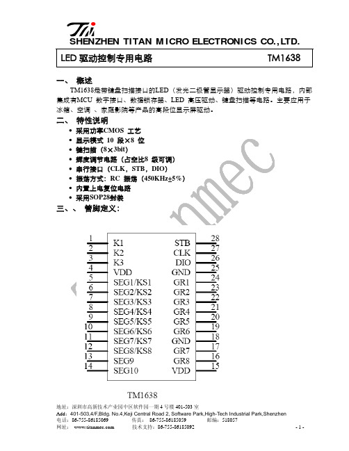
SHENZHEN TITAN M ICRO ELECTRONI CS CO.,LTD.
四、管脚功能说明:
符号
管脚名称
说明
DIN
数据输入
在时钟上升沿输入串行数据,从低位开始
DOUT STB
数据输出
在时钟下降沿输出串行数据,从低位开始。输出 为N-ch open drain
二、 特性说明
• 采用功率CMOS 工艺 • 显示模式 10 段×8 位 • 键扫描(8×3bit) • 辉度调节电路(占空比8 级可调) • 串行接口(CLK,STB,DIO) • 振荡方式:RC 振荡(450KHz+5%) • 内置上电复位电路 • 采用SOP28封装
CommScope HT3300H Double-Density 1310 nm Transmitt

DATA SHEETHeadend Optics Platform (CH3000)HT3300H SeriesDouble-Density 1310 nm Transmitter SystemThe CommScope HT3300H Series Double ‐Density 1310 nm Transmitter System provides high performance and a high rack density forward path transmission solution for Cable TV service providers.The high ‐density packaging design allows up to four (4) HT3300H series 1.2 GHz transmitters plus a CC3008 Communications Control Module to be stacked vertically and contained by the CA3008 module carrier, requiring only two chassis slots of a 3RU chassis. The compact solution supports up to 24 transmitters in a CH3000 chassis, including redundant power supplies.•Link loss budgets available from +3 to +12 dB •High rack density: 24 transmitters per 3RU chassis, with redundant power supplies •45–1218 MHz RF bandwidth •Dual RF inputs for BC and NC •Manual or AGC RF control •Low power consumption•Hot plug ‐in/out, individually replaceable transmitter modules•Front panel ‐20 dB input test point •Front panel laser On/Off switch•Local and remote status monitoring featuresFEATURESWhen installed in the chassis, the transmitters interface to a “zero‐slot” back plate, providing support for up to four HT3300H series transmitters. The figure below shows a fully loaded carrier mated to the BD31A4 Double‐Density back plate.HT3300H Series Quad‐Stack and CC3008 CommunicationsModule joined with a BD31A4 Multiplexing Back PlateThe CC3008 Communications Module installed at the top of a HT3300H series transmitter stack provides the communications interface between the transmitters and the CH3000 mid‐plane bus, allowing complete configuration and management control of the stack, both local and remote.HT3300H Series Double Density 1310 nm Transmitters (1.2 GHz Passband)CommScope’s HT3300H Series Double‐Density 1310 nm Transmitters are a key element of the CommScope HFC and Fiber Deep architectures. These 1.2 GHz transmitters are the ideal solution for expanding service demands of HDTV, VOD, cable telephony, and high‐speed DOCSIS.The HT3300H series transmitters are available with dual RF inputs for combining separate broadcast and narrowcast inputs within the transmitter. These transmitters are ideal for optical transport with link losses ranging from 3 to 12 dB.They include optional Automatic Gain Control circuitry to compensate for variations in the RF input level to the transmitter to maintain constant transmitter RF drive level to the laser.The above figure shows a front view of the CA3008 carrier components: a single HT33xxH Double‐Density Transmitter (left); a single CC3008 Communications Module (right), and a fully loaded “stack” (center) providing four (4) HT33xxH transmitters, requiring only 2 vertical slots of a CH3000 chassis. A fully loaded CH3000 chassis supports 24 Double‐Density 1310 nm transmitters and redundant power supplies.The compact design minimizes rack space requirements in headends or hubs and enhances deployment of traditional HFC, passive HFC, and fiber deep networks.Features•1310 nm transmitters: +3 to +15 dBm outputs •High rack density: 24 transmitters per 3RU chassis, with redundant power supplies•Low power consumption •Hot plug‐in/out, individually insertable •Front access ‐20 dB input test point •Front panel laser On/Off interlock control •Local and remote statusmonitoringHT3300H SPECIFICATIONSPhysicalDimensions11.5” D x 0.8” H x 2.0” W (29.2 x 2.0 x 5.1 cm)*Weight.75 lbs(.34 kg)* Four (4) transmitter units designed to be vertically stacked, plus a CC3008 Communications Module, and installedinside a CA3008 Module Carrier. The combination occupies two slots in a 3RU CH3000 Chassis.EnvironmentalOperating0°to +50°C (32°to 122°F)Storage‐40°to +85°C (‐40°to +185°F)Humidity5% to 95% non‐condensingRF and Optical InterfacesRF Input F‐type male (located on BD31A4 Back Plates)RF Input Test Point G‐type male (located at front panel, ‐20 dB nom.)Optical Connector SC/APC (located on BD31A4 Back Plates)Power RequirementsInput Voltage12 V DCPower Consumption10 W (per transmitter) including controller and back plate cooling fanGeneralWavelength1310 ±10 nmHot plug‐in/outAGC and manual RF level controlElectricalPassband45 to 1218 MHzFrequency Response (Flatness including Slope)•±1.0 dB (BC input @ 25°C)•±1.0 dB (NC input relative to BC input)Nominal RF Input Levels (dBmV/ch)AGC Mode Manual Mode•NTSC 54‐552 MHz:1515•QAM 552‐1002 MHz: 1515NOTE: NC QAM signals are attenuated 6 dB before internal combining with BC analog signalsManual Gain Control Range0 to ‐6 dB minimumManual Gain Control Step0.5 dBRF Input Impedance75 Ω, nomRF Input Return Loss18 dB, minLevel Stability ±0.5 dB typ., ±1 dB max.Fiber‐only link performance1(with full channel loading of 54–552 MHz analog and 552–1002 MHz QAM)•CNR2: 52 dB •CSO: 65 dB •CTB: 70 dB •XMOD: 60 dB256‐QAM BER< 10–5(pre‐FEC, ITU‐C)MER> 37 dB to 50°C; > 36 dB to 65°COptical Fiber loss and PerformanceLink Loss (dB)Output Power (dBm)Fiber Loss (max) (dB)3 2.75–3.75 2.56 5.75–6.75 5.598.75–9.758.5109.75–10.759.51110.75–11.7510.51211.75–12.7511.5NOTES:1.Guaranteed over full operating temperature rangeR measurements for NTSC channels made over 4 MHz noise bandwidth3.With AGC enabled, capture range is ±3 dBBD31A4‐100 BACK PLATE SPECIFICATIONSSpecificationPhysical Dimensions 7.2” D x 5.2” H x 2.0” W* (18.2 x 13.2 x 5.1 cm)Weight 2.0 lb (0.91 kg)Environmental Operating ‐20°to +65°C (‐4°to 149°F)Storage ‐40°to +85°C (‐40°to +185°F)Humidity5% to 95% non ‐condensingPower Requirements Input Voltage 12 V DCPower Consumption 5 W max (2.5 W Typ), including the replaceable cooling fan OpticalThrough 4 SC/APC connectors, the BD31A4‐100 provides optical pass ‐through from the HT3300H transmitter.Optical Insertion Loss 0.2 dB Typ; 0.4 dB MaxRefer to the HT3300H product specifications for more information.RF InterfaceThrough 8 (eight) F ‐type RF connectors, the BD31A4‐100 provides RF pass ‐through to the HT3300H transmitter.•4 BC and 4 NC (1 BC/NC pair pertransmitter)BD31A4‐100‐H12F ‐0‐AS Back Plate CA3008 ModuleCarrierBD31A4 Double ‐Density Back PlatesThe BD31A4 is a double ‐density back plate that provides a choice of 4 separate BC and 4 separate NC RF inputs, or 1 common BC and 4 separate NC RF inputs, for four HT3300H series transmitters.The BD31A4 provides RF input and optical connections to or from the HT3300H transmitters.BD31A4‐100‐H12F ‐0‐AS is a double density back plate that provides 4 separate BC inputs and 4 separate NC RF inputs for four HT3300H transmitters. Also supports four separate optical output SC/APC connectors.BD31A4‐100‐H10F ‐0‐AS is a double density back plate that provides 1 common BC input and 4 separate NC RF inputs for four HT3300H series transmitters. Also supports four separate optical output SC/APC connectors.H T 33**H –D –1310–2–A SDouble Density, 1310 nm Transmitter (1.2 GHz)03 = 3 dB Link 1 GHz Transmitter 06 = 6 dB Link 1 GHz Transmitter 09 = 9 dB Link 1 GHz Transmitter 10 = 10 dB Link 1 GHz Transmitter 11 = 11 dB Link 1 GHz Transmitter 12 = 12 dB Link 1 GHz Transmitter Connector Type: SC/APCB D 31A 4–100–H 1*F –0–A SDouble Density Back plate for 4 HT3xxx Full Spectrum Transmitters with SC/APC Connector2 = 4 separate BC inputs and 4 separate NC RF inputs for 4 transmitters 0 = 1 common BC input and 4 separate NC RF inputs for 4 transmitters Connector Type: SC/APCHT3300H TransmitterBack PlatesContact Customer Care for product information and sales:•United States: 866‐36‐ARRIS •International: +1‐678‐473‐5656RELATED PRODUCTSCH3000 Chassis Optical Patch Cords Optical Transmitters Optical Passives Digital ReturnInstallation ServicesNote: Specifications are subject to change without notice.Copyright Statement:©2022CommScope,Inc.All rights reserved.ARRIS and the ARRIS logo are trademarks of CommScope,Inc.and/or its affiliates.All other trademarks are the property of their respective owners.No part of this content may be reproduced in any form or by any means or used to make any derivative work (such as translation,transformation,or adaptation)without written permission from CommScope,Inc and/or itsaffiliates (“CommScope”).CommScope reserves the right to revise or change this content from time to time without obligation on the part of CommScope to provide notification of such revision or change.System AccessoriesC C 3008Communications Control ModuleC A 3008Module CarrierH T 3F I L DFiller Module for Double ‐Density Slots。
红外线遥控接收头型号及参数:
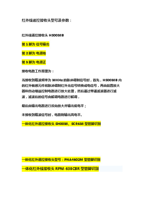
红外线遥控接收头型号及参数:红外线遥控接收头 HS0038B第1脚为信号输出第2脚为电源地第3脚为电源正接收电路工作原理为:当接收到载波频率为38KHz的脉冲调制信号时,首先,HS0038B内的红外敏感元件将脉冲调制红外光信号转换成电信号,再由前置放大器和自动增益控制电路进行放大处理,然后通过带通滤波器进行滤波,滤波后的信号由解调电路进行解调,最后由输出电路进行反向放大并输出低电平;未接收到载波信号时,电路则输出高电平。
一体化红外遥控接收头SH0038、SCR638型管脚识别一体化红外遥控接收头型号:PNA4602M 型管脚识别一体化红外线接收头RPM-638CBR型管脚识别红?外?一?体?化?接?收?头?型号:T?S?O?P?1?8?3?8管脚识别:一体化红外线接收头原理图及管脚排列什么是遥控接收头?所谓接收头就是将光敏二极管和放大电路组合到一起的元件,这些元件完成接收、放大、解调等功能。
所有红外线遥控器的输出都是用编码后的串行数据对30~56kHz的方波进行脉冲幅度调制而产生的。
如果直接对已调波进行测量,由于单芯片系统的指令周期是微秒(μs),而已调波的脉宽只有20多μs,会产生很大的误差。
因此先要对已调波进行解调,对解调后的波形进行测量。
红外一体化接收头:红外线接收头一般是接收、放大、解调一体头,一般红外信号经接收头解调后,数据“0”和“1”的区别通常体现在高低电平的时间长短或信号周期上,单片机解码时,通常将接收头输出脚连接到单片机的外部中断,结合定时器判断外部中断间隔的时间从而获取数据。
重点是找到数据“0”与“1”间的波形差别。
输出端可与CMOS、TTL电路相连,这种接收头广泛用在空调,电视,VCD等电器中。
早期的红外一体化接收头一般由集成电路与接收二极管焊接在一块电路板上完成的,这种接收头具有体积大的缺点,现在的接收头是集成电路与接收二极管封装在一起的,不可拆,不可修,体积很小。
大多数接收头供电为5V,有极少数早期的接收头为12V供电。
MB85RC16PNF-G-JNE1;中文规格书,Datasheet资料

FUJITSU SEMICONDUCTORDATA SHEETCopyright©2011 FUJITSU SEMICONDUCTOR LIMITED All rights reserved 2011.6Memory FRAM16 K (2 K × 8) Bit I 2CMB85RC16■DESCRIPTIONThe MB85RC16 is an FRAM (F erroelectric Random Access Memory) chip in a configuration of 2,048 words × 8 bits, using the ferroelectric process and silicon gate CMOS process technologies for forming the nonvolatile memory cells.Unlike SRAM, the MB85RC16 is able to retain data without using a data backup battery.The memory cells used in the MB85RC16 have at least 1010 Read/Write operation endurance per bit, which is a significant improvement over the number of read and write operations supported by other nonvolatile memory products.The MB85RC16 can provide writing in one byte units because the long writing time is not required unlike Flash memory and E 2PROM. Therefore, the writing completion waiting sequence like a write busy state is not required.■FEATURES•Bit configuration : 2,048 words × 8 bits •Operating power supply voltage : 2.7 V to 3.6 V •Operating frequency : 1 MHz (Max) •T wo-wire serial interface : Fully controllable by two ports: serial clock (SCL) and serial data (SDA).•Operating temperature range : − 40 °C to + 85 °C •Data retention : 10 years ( + 75 °C) •Read/Write endurance : 1010 times •Package : Plastic / SOP , 8-pin (FPT -8P-M02)•Low power consumption : Operating current 0.1mA (Max: @1 MHz), Standby current 0.1 μA (Typ)DS501-00001-2v0-EMB85RC16■PIN FUNCTIONAL DESCRIPTIONSPinNumberPin Name Functional Description1 to 3NC Unconnected pins Leave it unconnected.4VSS Ground pin5SDA Serial Data I/O pinThis is an I/O pin of serial data for performing bidirectional communication of mem-ory address and writing or reading data. It is possible to connect some devices. It is an open drain output, so a pull-up resistance is required to be connected to the external circuit.6SCL Serial Clock pinThis is a clock input pin for input/output timing serial data. Data is sampled on the rising edge of the clock and output on the falling edge.7WP Write Protect pinWhen Write Protect pin is “H” level, writing operation is disabled. When Write Pro-tect pin is “L” level, the entire memory region can be overwritten. Reading operation is always enabled regardless of the Write Protect pin state. The write protect pin is internally pulled down to VSS pin, and that is recognized as “L” level (the state that writing is enabled) when the pin is the open state.8VDD Supply Voltage pinMB85RC16■I2C (Inter-Integrated Circuit)The MB85RC16 has the two-wire serial interface and the I2C bus, and operates as a slave device.The I2C bus defines communication roles of “master” and “slave” devices, with the master side holding the authority to initiate control. Furthermore, a I2C bus connection is possible where a single master device is connected to multiple slave devices in a party-line configuration.2MB85RC16■I2C COMMUNICATION PROTOCOLThe I2C bus provides communication by two wires only, therefore, the SDA input should change while SCL is the “L” level. However, when starting and stopping the communication sequence, SDA is allowed to change while SCL is the “H” level.•Start ConditionTo start read or write operations by the I2C bus, change the SDA input from the “H” level to the “L” level while the SCL input is in the “H” level.•Stop ConditionTo stop the I2C bus communication, change the SDA input from the “L” level to the “H” level while the SCL input is in the “H” level. In the reading operation, inputting the stop condition finishes reading and enters the standby state. In the writing operation, inputting the stop condition finishes inputting the rewrite data.Note : The FRAM device does not need the programming wait time (t WC) after issuing the Stop Condition during the write operation.MB85RC16■ACKNOWLEDGE (ACK)In the I2C bus, serial data including memory address or memory information is sent in units of 8 bits. The acknowledge signal indicates that every 8 bits of the data is successfully sent and received. The receiver side usually outputs the “L” level every time on the 9th SCL clock after every 8 bits are successfully trans-mitted. On the transmitter side, the bus is temporarily released on this 9th clock to allow the acknowledge signal to be received and checked. During this released period, the receiver side pulls the SDA line down to indicate that the communication works correctly.If the receiver side receives the stop condition before transmitting the acknowledge “L” level, the read operation ends and the I2C bus enters the standby state. If the acknowledge “L” level is not detected, and the Stop condition is not sent, the bus remains in the released state without doing anything.■MEMORY ADDRESS STRUCTUREThe MB85RC16 has the memory address buffer to store the 11-bit information for the memory address.As for byte write, page write and random read commands, the complete 11-bit memory address is configured by inputting the memory upper address (3 bits) and the memory lower address (8 bits), and saving to the memory address buffer and access to the memory is performed.As for a current address read command, the complete 11-bit memory address is configured by inputting the memory upper address (3 bits) and by the memory address lower 8-bit which has saved in the memory address buffer, and saving to the memory address buffer and access to the memory is performed.MB85RC16■DEVICE ADDRESS WORDF ollowing the start condition, the 8 bit device address word is input. Inputting the device address word decideswhether the master or the slave drives the data line. However, the clock is always driven by the master. The device address word (8bits) consists of a device T ype code (4bits), memory upper address code (3bits), anda Read/Write code (1bit).•Device Type Code (4bits)The upper 4 bits of the device address word are a device type code that identifies the device type, and are fixed at “1010” for the MB85RC16.•Memory Upper Address Code (3bits)Following the device type code, the 3 bits of the memory upper address code are input.The slave address selection is not performed by the external pin setting on this device. These 3 bits are not the setting bits for the slave address, but the upper 3-bit setting bits for the memory address.•Read/Write Code (1bit)The 8th bit of the device address word is the R/W (Read/Write) code. When the R/W code is “0” input, a write operation is enabled, and the R/W code is “1” input, a read operation is enabled for the MB85RC16. If the device code is not “1010”, the Read/Write operation is not performed and the standby state is chosen.MB85RC16■DATA STRUCTUREThe master inputs the device address word (8 bits) following the start condition, and then the slave outputs the Acknowledge “L” level on the ninth bit. After confirming the Acknowledge response, the sequential 8-bit memory lower address is input, to the byte write, page write and random read commands.As for the current address read command, inputting the memory lower address is not performed, and the address buffer lower 8-bit is used as the memory lower address.When inputting the memory lower address finishes, the slave outputs the Acknowledge “L” level on the ninth bit again.Afterwards, the input and the output data continue in 8-bit units, and then the Acknowledge “L” level is output for every 8-bit data.MB85RC16■FRAM ACKNOWLEDGE -- POLLING NOT REQUIREDThe MB85RC16 performs the high speed write operations, so any waiting time for an ACK* by the acknowl-edge polling does not occur.*: In E2PROM, the Acknowledge Polling is performed as a progress check whether rewriting is executed or not.It is normal to judge by the 9th bit of Acknowledge whether rewriting is performed or not after inputting the start condition and then the device address word (8 bits) during rewriting.■WRITE PROTECT (WP)The entire memory array can be write protected by setting the WP pin to the “H” level. When the WP pin is set to the “L” level, the entire memory array will be rewritten. Reading is allowed regardless of the WP pin's “H” level or “L” level.Do not change the WP signal level during the communication period from the start condition to the stop condition.Note : The WP pin is pulled down internally to VSS pin, therefore if the WP pin is open, the pin status is detected as the “L” level (write enabled).MB85RC16■COMMAND•Byte WriteIf the device address word (R/W “0” input) is sent after the start condition, an ACK responds from the slave.After this ACK, write memory addresses and write data are sent in the same way, and the write ends by•Page WriteIf data is continuously sent after the following address when the same command (expect stop condition) as Byte Write was sent, a page write is performed. The memory address rolls over to first memory address (000H)at the end of the address. Therefore, if more than 2 Kbytes are sent, the data is overwritten in orderMB85RC16•Current Address ReadIf the last write or read operation finishes correctly up to the end of stop condition, the memory address that was accessed last remains in the memory address buffer (the length is 11 bits).When sending this command without turning the power off, it is possible to read from the memory address n+1 which adds 1 to the total 11-bit memory address n, which consists of the memory upper address 3-bit from the device address word input and the lower 8-bit of the memory address buffer. If the memory address n is the last address, it is possible to read with rolling over to the head of the memory address (000H). The current address (address that the memory address buffer indicates) is undefined immediately after turning•Random ReadThe one byte of data from the memory address as saved in the memory address buffer can be read out synchronously to SCL by specifying the address in the same way as for a write, and then issuing another start condition and sending the Device Address Word (R/W “1” input).Setting values for the first and the second memory upper address codes should be the same.The final NACK (SDA is the “H” level) is issued by the receiver that receives the data. In this case, this bit is分销商库存信息: FUJITSUMB85RC16PNF-G-JNE1。
- 1、下载文档前请自行甄别文档内容的完整性,平台不提供额外的编辑、内容补充、找答案等附加服务。
- 2、"仅部分预览"的文档,不可在线预览部分如存在完整性等问题,可反馈申请退款(可完整预览的文档不适用该条件!)。
- 3、如文档侵犯您的权益,请联系客服反馈,我们会尽快为您处理(人工客服工作时间:9:00-18:30)。
4
型号: LF1638B
Typical Electrical Curves at Temp=25℃
5
型号: LF1638B
9.极限参数: 项目 供应电压 工作温度 储存温度 焊接温度 10.推荐使用条件: 项目 工作电压 输入频率 工作温度 11.接收角度: 符号 VCC Topr Tstg Tsol 规格 -0.3—6.5 -25— +85 -40 —— +125 260(5S) 单位 V ℃ ℃ ℃
6
LF1638B
1
型号:LF1638B
1.特性: ●小型设计; ●内置专用 IC; ●宽角度及长距离接收; ●抗干挠能力强; ●能抵挡环境干挠光线; ●低电压工作; 2.应用: ■视听器材(音箱,电视,录影机,碟机) ■家庭电器(冷气机,电风扇,电灯) ■其它红外线遥控产品; LF1638B
3.尺寸:
2
型号: LF1638B
4.应用电路图:
5.原理图:
6.光电参数(T=25℃ Vcc=5v f0=38KHZ): 参 数 符号 VCC Icc Ice L θ1/2 f0 fBW VOL VOH TPWL TPWH -3Db Bandwidth Vin=0V Vcc=5V Vcc=5V Vin=50mVp-p Vin=50mVp-p Vcc-0.3 500 540
无信号输入时 ※
测试条件
Min 2.7 0.6 0.1 13
Type 0.8 15
+/-35
Max 5.5 0.5
单 位 V mA mA M Deg KHZ
工作电压 工作电流 静态电流 接收距离 接收角度 载波频率 BMP 宽度 低电平输出 高电平输出 输出脉冲 宽 度
38 8 0.4 Vcc 700 740
600 640
kHz V V μS μS
※ 光轴上测试,以宽度 600/900μs 为发射脉冲,在 5CM 之接收范围内,取 50 次接收脉冲之平均值。
3
型号: LF1638B
7.测试波型:
8.特性曲线图(Characteristics Curve)(Tamb=25℃ unless otheruise specified):
符号 Vcc FM Topr
Min 2.7
Typ ----38
Mnx 5.5
单位 V kHz
-20
25
80
℃
12.使用注意: 1).在无任何外加压力及影响品质的环境下储存及使用; 2).在无污染气体或海风(含盐分)的环境下储存及使用; 3).在低湿度环境下储存及使用; 4).在规定的条件下焊接引线管脚,焊接后,请勿施加外力; 5).请勿清洗本产品,使用前,请先用静电带将作业员及电烙铁连接落地线; 6).请注意保护红外线接收器的接收面,沾污或磨损后会影响接收效果,同时不要触碰表面。