A_data_model_for_route_planning_in_the_case_of_forest_fires
BUILDING_THE_BRIDGE

O n October 17 and 18, 2023, the 3rd Belt and Road Forum for International Cooperation was held in Beijing, China. H.E. Mr. Srettha Thavisin, PrimeMinister of the Kingdomof Thailand, attended and engaged in discussionswith representatives from Chinese enterprises on bilateral investment and cooperation. On social media, he posted a doodle of a map of the proposed Land Bridge project in southern Thailand and commentedon the encouraging resultsof his communication with representatives from Chinese railway enterprises.On November 3, Srettha Thavisin met Chinese Ambassador to ThailandHan Zhiqiang and stressed Thailand’s enthusiasm about cooperating with China to fund and build the Land Bridge. Srettha Thavisin pledged to authorize the Ministry of Transport and Board of Investment (BOI) to negotiate with the Chinese government on specific investment means and other cooperation details of the project.Snowballing attentionon the project has ensured the bridge becomes a major component of China-Thailand connectivity cooperation. Canal or BridgeThe Land Bridge projectis located on the Isthmus ofKra, the narrow neck of theMalay Peninsula. The isthmusseparates the Gulf of Thailandto the east from the AndamanSea to the west and is only56 kilometers wide at itsnarrowest point.The area was an importantroute for the Maritime SilkRoad as early as in the HanDynasty (206 BC-AD 220).According to the Treatiseon Geography in the Book ofHan, the official dynastichistory of the Han Dynasty,the ancient Chenli Kingdomand Fugandulu Kingdom weresituated on the eastern andwestern sides of the MalayPeninsula, respectively, andpeople had to walk for morethan ten days to travel betweenthe two locations.The geographical dividemade maritime transportationbetween the two areas quiteinconvenient because shipshad to circumnavigate thepeninsula and cross the Straitof Malacca to shuttle back andforth, which contributed to thedevelopment of Singapore.Many leaders of Thailandhave sought to connect the twosides and develop the area intoa shipping, trade, and financialhub of Southeast Asia. As earlyas in the Ayutthaya Kingdom(1351-1767), nobles attempted todig a canal across the Isthmusof Kra to connect the PacificOcean and the Indian Ocean.Before the 20th Century,British and French colonizersrepeatedly proposed to theroyal family of the Chakridynasty that they could dig acanal in the area. In the 21stCentury, canal plans havecontinued to regularly featurein the planning of the Thaigovernment.However, the canal has stillnever passed the conceptualstage despite hundreds of yearsof discussion and planning,which could be attributed tothree specific factors.First, economic factors.A canal would help cut thetravel time between the twomajor oceans by two to fivedays by eliminating 900 to1,200 kilometers, but thatadvantage would be dwarfedby the performance of majorglobal canals. For example,the Panama Canal shortensvoyages by over 8,200kilometers, and the Suez Canalreduces journeys by morethan 10,000 nautical miles.Therefore, the appeal of a canalin the Isthmus of Kra wouldbe fairly limited, and it wouldlikely take much longer for theeconomic benefits to cover themassive construction costs.Second is the environment.The canal would bring notonly many ships but alsotheir pollution, whichcould be detrimental to thelocal tourism industry andecosystem of the beautifulThe Land Bridge project will bring both opportunities and challenges to ThailandSnowballingattention onthe projecthas ensuredthe bridgebecomesa majorcomponentof China-Thailandconnectivitycooperation.62Hand-drawn illustration of the Land Bridge project by Prime Minister of Thailand Srettha Thavisin. (SOCIAL MEDIA PLATFORM)Business & Industry65outlining plans to develop the Eastern Economic Corridor (EEC) and Southern Economic Corridor (SEC), boost industrial upgrades, and enhance international competitiveness.Currently, EEC is enjoying rapid progress, with the China-Laos-Thailand railway playing a key role in aligning it with the BRI. Construction of the SEC is poised to become a focal point for the new Thai government’s endeavors, and the Land Bridge project is expected to be linked to China’s 21st Century Maritime Silk Road, which has strategic importance for both China and Thailand.The Land Bridge will advance economic and trade cooperationbetween both countries and facilitate alignment of supply and demand as well as connectivity.Thailand’s southern region is a major agricultural production area, and its agriculture contributes approximately 30 percent to the region’s GDP. The region has huge export demand for products such as rubber, seafood, wood products, and palm oil, but local demand for imports is smaller. This imbalance means that many vessels have to sail empty to local ports, which increases transportation costs.Hence, insufficient shipping capacity has pushed many products produced in southern Thailand to take a longer route. They would first be transported by land to the port of Penang in Malaysia or ports in Bangkok and Laem Chabang in eastern Thailand before being exported abroad. The problem has also dampened trade between China and Thailand despite China being the largest export market for agricultural products from southern Thailand. Laem Chabang Port and Chumphon Port, included in the Land Bridge project, are each designed to handle throughput of 20 million TEUs, making them well-positioned to address this problem effectively.The Thai government also proposed seizing the Land Bridge project as an opportunity to promote industrial upgrading and transformation in southern Thailand. The plan includesreclaiming land in the port areas and building supporting facilities as well as establishing industrial zones to attract foreign investment. The country has outlined plans to import electronic components from China, process them in the Land Bridge area, and then export the finished products to countries in Southeast Asia, the Indian Ocean, and along the Pacific coast, which would make the country a crucial link in the transoceanic supply chain.China and Thailand have previously collaborated on the construction of the Thai-Chinese Rayong Industrial Zone in eastern Thailand, which has since served as a successful model for bilateral investment and industrial cooperation. Many expect the Land Bridge to replicate this cooperation model in southern Thailand.In addition to promoting China-Thailand trade, the Land Bridge project will inject greater vitality into cooperation between China and ASEAN. China-ASEAN trade and investment has been gaining momentum since the entry intoforce of the Regional Comprehensive Economic Partnership (RCEP) in 2022. According to the plan for the Land Bridge, Chumphon Port will become the largest port on the western coast of the Gulf of Thailand, and the oil and gas pipelines included in the project are designed to alleviate the increasing burden on the Strait of Malacca. Since Thailand is situated at the geographic center of ASEAN, the Land Bridge has great potential to become a hub for shipping, trade, and energy transportation. China’s extensive participation in the project will create a new route to extend the 21st Century Maritime Silk Road. The Thai government expects big things from the Land Bridge, and Prime Minister Srettha Thavisin has expressed considerable enthusiasm for China’s participation in theproject. However, the project still faces multiple difficulties and challenges.The first problem is funding. According to data released by the Thai Cabinet, total investment in the Land Bridge project will exceed 1.012 trillion Thai Baht (US$27.72 billion), which is more than twice the total cost of the first and second phases of the Bangkok-Nong Khai section of the China-Thailand High-speed Railway. The construction period for the Land Bridge will be lengthy and will involve massive costs as well as significant investment risks. Now, the Thai government is attracting investment for the project through a Public-Private Partnership (PPP) model, which brings the challenge of coordinating the interests of various participants.The second obstacle isenvironmental consideration. The Land Bridge could have adverse effects on the marine ecosystem in Southern Thailand and potentially lead to losses for local tourism and fishery due to increased maritime traffic. Therefore, multiple rounds of environmental assessments are necessary before advancing theproject, including listening to voices from local people and gaining their trust to address the concerns of the community.Lastly, the project faces challenges from both domestic and international political environments. Domestically, the Thai government needs to address issues of uneven resource allocation across regions, and internationally, it must navigate competition with neighboring countries for maritime resources. As the American Indo-Pacific strategy proceeds, the United States and India could becomenervous about China gaining greater influence in the Gulf of Thailand and the Andaman Sea. If Thailand adheres to its traditional conservative “balanced diplomacy,” the Land Bridge project could get stuck.About the author Tian Lin is a lecturer at the School of Asian Studies at Beijing Foreign Studies University.。
automodel.from_pretrained的参数

automodel.from_pretrained的参数automodel.from_pretrained是PaddlePaddle深度学习框架中的一个重要功能,它能够从预训练模型中加载并初始化模型参数,从而快速构建出可用的模型。
在使用automodel.from_pretrained时,有一些参数是必须要了解和设置的。
一、参数概述automodel.from_pretrained函数接受一系列可选参数,用于控制模型的加载和初始化过程。
这些参数包括但不限于模型路径、数据增强、模型保存等。
通过合理设置这些参数,可以更好地适应不同的应用场景。
二、常用参数详解1. model_path:模型路径,指定要加载的预训练模型的路径。
该参数是必需的,必须提供正确的模型路径才能调用automodel.from_pretrained。
2. model_name:模型名称,指定要加载的预训练模型的名称。
该参数用于在指定的模型路径下查找对应的模型文件。
3. pretrained_params:预训练模型参数,指定要从预训练模型中加载的参数。
这些参数可以通过PaddlePaddle提供的API进行设置和调整。
4. data_dir:数据目录,指定要进行模型训练的数据集的路径。
该参数用于将数据集加载到模型中,以便进行模型的训练和验证。
5. save_dir:保存目录,指定要将训练得到的模型保存到的路径。
该参数可用于在训练过程中保存模型,并在需要时进行加载和验证。
6. use_gpu:是否使用GPU进行模型训练。
该参数用于控制是否使用GPU进行模型的计算和训练,可以根据硬件设备情况进行设置。
7. optimizer:优化器,指定用于模型训练的优化器类型。
常见的优化器类型包括Adam、SGD等,可以根据具体任务需求进行选择和设置。
三、使用示例```pythonimport paddlefrom paddle.vision.models import resnet50# 加载预训练模型参数pretrained_params = resnet50(pretrained=True)model = paddle.Model(model_name="resnet50", pretrained_params=pretrained_params)```以上代码中,我们首先使用resnet50函数创建了一个预训练的ResNet-50模型,并将其作为预训练模型参数传递给automodel.from_pretrained函数进行初始化。
ISIGHT工程优化案例分析
iSIGHT工程优化实例分前言随着设备向大型化、高速化等方向的发展,我们的工业设备(如高速列出、战斗机等)的复杂程度已远超乎平常人的想象,装备设计不单要用到大量的人力,甚至已牵涉到了数十门学科。
例如,高速车辆设计就涉及通信、控制、计算机、电子、电气、液压、多体动力学、空气动力学、结构力学、接触力学、疲劳、可靠性、维修性、保障性、安全性、测试性等若干学科。
随着时代的进步,如今每个学科领域都形成了自己特有研究方法与发展思路,因此在设计中如何增加各学科间的沟通与联系,形成一个统一各学科的综合设计方法(或平台),成为工程和学术界所关注的重点。
多年来,国外已在该领域做了许多著有成效的研究工作,并开始了多学科优化设计方面的研究。
就国外的研究现状而言,目前已经实现了部分学科的综合优化设计,并开发出了如iSIGHT、Optimus等多学科商业优化软件。
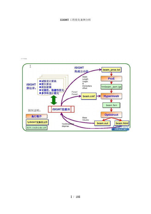
iSIGHT是一个通过软件协同驱动产品设计优化的多学科优化平台,它可以将数字技术、推理技术和设计搜索技术有效融合,并把大量需要人工完成的工作由软件实现自动化处理。
iSIGHT软件可以集成仿真代码并提供智能设计支持,对多个设计方案进行评估和研究,从而大大缩短了产品的设计周期,显著地提高了产品质量和可靠性。
目前市面上还没有关于iSIGHT的指导书籍,而查阅软件自带的英文帮助文档,对许多国内用户而言尚有一定的难度。
基于以上现状,作者根据利用iSIGHT做工程项目的经验编写了这本《iSIGHT工程优化实例》。
本书分为优化基础、工程实例和答疑解惑三个部分,其中工程实例中给出了涉及铁路、航空方面多个工程案例,以真实的工程背景使作者在最短的时间内掌握这款优化的软件。
本书在编写的过程中,从互联网上引用了部分资料,在此对原作者表示衷心地感谢!我要真诚地感谢大连交通大学(原大连铁道学院)和王生武教授,是他们给了我学习、接触和使用iSIGHT软件机会!仅以本书献给所有关心我的人!赵怀瑞2007年08月于西南交通大学目录第一章认识iSIGHT (1)1.1 iSIGHT软件简介 (1)1.2 iSIGHT工作原理简介 (5)1.3 iSIGHT结构层次 (6)第二章结构优化设计理论基础 (8)2.1 优化设计与数值分析的关系 (8)2.2 优化设计基本概念 (8)2.3 优化模型分类 (10)2.4 常用优化算法 (11)2.5大型结构优化策略与方法 (25)第三章iSIGHT软件界面与菜单介绍 (32)3.1 iSIGHT软件的启动 (32)3. 2 iSIGHT软件图形界面总论 (32)3.3 任务管理界面 (36)3.4 过程集成界面 (43)3.5 文件分析界面 (46)3.6 过程监控界面 (49)3.4 多学一招—C语言的格式化输入/输出 (53)第四章iSIGHT优化入门 (54)4.1 iSIGHT优化基本问题 (54)4.2 iSIGHT集成优化的一般步骤 (54)4.3 iSIGHT优化入门—水杯优化 (55)第五章模压强化工艺优化 (76)5.1 工程背景与概述 (76)5.2 优化问题描述 (76)5.3 集成软件的选择 (77)5.4有限元计算模型介绍 (77)5.5 模压强化优化模型 (78)5.8 iSIGHT集成优化 (81)5.9优化结果及其分析 (88)5.10 工程优化点评与提高 (89)第六章单梁起重机结构优化设计 (90)6.1 工程与概述 (90)6.2 优化问题描述 (90)6.3 集成软件的选择 (91)6.4起重机主梁校核有限元计算模型介绍 (92)6.5 主梁优化模型 (92)6.8 iSIGHT集成优化 (94)6.9优化结果及其分析 (99)6.10 工程优化点评与提高 (100)6.11 多学一招—ANSYS中结果输出方法 (100)第七章涡轮增压器压气机叶片优化设................................................... 错误!未定义书签。
静态时序分析(Static Timing Analysis)

Post-layout
Design Planning
Annotated Delays & parastics Sign-off Constraints Place & Route
STA的基本思想
STA 基本思想:不需要测试向量,仅由电路的拓扑结构,找出 电路中所有信号的可能路径,通过计算延迟,确定电路中是否 有时序错误(violation)。
CLK 路径4
Back-Annotation and delay calculation (1)
1. For Pre-layout, statistical wire-load models are used 2. For post-floor planning/layout, delays can be back-annotated Standard delay format (SDF) Lumped RC information Detailed/reduced RC information RSPF/DSPF/SPEF Path Delay的计算 Path delay为路径上的所有cell delay和net delay的总和: Cell delay:从cell的输入或双向pin到输出或双向pin的延时 Net delay:某个输出pin状态变化到它驱动的相应输入pin状态变化的延时 用线性延时计算cell delay Cell delay=DI + DS + DT DI = Instrinsic Delay DS =Slope delay=DT previews * sslope delay factor DT =Transition Delay=Rdrive *(Cpins +Cwires) Rdrive = drive strength of the cell’s output pin Cpins = Capacitance of all the pins from the cells on the net Cwire= Wireload model or back annotated data for nete
PDA TR59中英文对照(利用统计学进行产品监控)

Technical Report No.59
制药技术的传播者 GMP理论的践行者
目录
1.0 INTRODUCTION 简介 ...................................................................................... 4 1.1 PURPOSE AND SCOPE 目的和范围 ................................................................... 4
例.............................................................................. 44
2
制药技术的传播者 GMP理论的践行者
In light of the increased focus on this topic, this PDA Task Force recognized the need to provide guidance to help companies identify and use statistical methods. The primary objective of this Task Force was to convey the appropriate use of statistical methods at a level most can understand. 鉴于人们对这一主题越来越重视,PDA 工作组认识到应该建立指南帮助公司识别和使用统计方法。 该工作组的基本目的是让大多数人能够适当应用统计方法。
Moxa ICS-G7850A系列48G+210GbE层3全光纤模块管理交换机产品介绍说明书

ICS-G7850A Series48G+210GbE Layer 3full Gigabit modular managed EthernetswitchesFeatures and Benefits•Up to 48Gigabit Ethernet ports plus 210G Ethernet ports •Up to 50optical fiber connections (SFP slots)•Up to 48PoE+ports with external power supply (with IM-G7000A-4PoEmodule)•Fanless,-10to 60°C operating temperature range•Modular design for maximum flexibility and hassle-free future expansion •Hot-swappable interface and power modules for continuous operation •Turbo Ring and Turbo Chain (recovery time <20ms @250switches)1,andSTP/RSTP/MSTP for network redundancy•Isolated redundant power inputs with universal 110/220VAC power supplyrange•Supports MXstudio for easy,visualized industrial network management •V-ON™ensures millisecond-level multicast data and video network recoveryCertificationsIntroductionProcess automation and transportation automation applications combine data,voice,and video,and consequently require high performance and high reliability.The ICS-G7850A Series full Gigabit backbone switches’modular design makes network planning easy,and allows greater flexibility by letting you install up to 48Gigabit Ethernet ports plus 210Gigabit Ethernet ports.The fanless switches support the Turbo Ring,Turbo Chain,and RSTP/STP redundancy technologies,and come with an isolated redundant power supply to increase system reliability and the availability of your network backbone.Additional Features and Benefits•Layer 3switching functionality to move data and information across networks (ICS-G7800A Series)•Advanced PoE management functions:PoE output setting,PD failure check,PoE scheduling,and PoE diagnostics (with IM-G7000A-4PoE module)•Command line interface (CLI)for quickly configuring major managed functions•Supports advanced VLAN capability with Q-in-Q tagging•DHCP Option 82for IP address assignment with different policies •Supports EtherNet/IP and Modbus TCP protocols for device management and monitoring•Compatible with PROFINET protocol for transparent data transmission•Digital inputs for integrating sensors and alarms with IP networks •Redundant,dual AC power inputs•IGMP snooping and GMRP for filtering multicast traffic•IEEE 802.1Q VLAN and GVRP protocol to ease network planning •QoS (IEEE 802.1p/1Q and TOS/DiffServ)to increase determinism •Port Trunking for optimum bandwidth utilization•TACACS+,SNMPv3,IEEE 802.1X,HTTPS,and SSH to enhance network security•Access control lists (ACL)increase the flexibility and security of network management•SNMPv1/v2c/v3for different levels of network management •RMON for proactive and efficient network monitoring•Bandwidth management to prevent unpredictable network status •Lock port function for blocking unauthorized access based on MAC address•Port mirroring for online debugging•Automatic warning by exception through email and relay output1.If the port link speed is 1Gigabit or higher,the recovery time is <50ms.SpecificationsInput/Output InterfaceAlarm Contact Channels Relay output with current carrying capacity of2A@30VDCDigital Inputs+13to+30V for state1-30to+1V for state0Max.input current:8mAEthernet Interface10GbE SFP+Slots2Slot Combination12slots for4-port interface modules(10/100/1000BaseT(X),or PoE+10/100/1000BaseT(X),or100/1000BaseSFP slots)2Standards IEEE802.1D-2004for Spanning Tree ProtocolIEEE802.1p for Class of ServiceIEEE802.1Q for VLAN TaggingIEEE802.1s for Multiple Spanning Tree ProtocolIEEE802.1w for Rapid Spanning Tree ProtocolIEEE802.1X for authenticationIEEE802.3for10BaseTIEEE802.3ab for1000BaseT(X)IEEE802.3ad for Port Trunk with LACPIEEE802.3u for100BaseT(X)and100BaseFXIEEE802.3x for flow controlIEEE802.3z for1000BaseSX/LX/LHX/ZXIEEE802.3af/at for PoE/PoE+outputIEEE802.3ae for10Gigabit EthernetEthernet Software FeaturesManagement ARPBack Pressure Flow ControlBOOTPDDMDHCP Option66/67/82DHCP Server/ClientFlow controlIPv4LLDPPort MirrorRARPRMONSCPSMTPSNMP InformSNMPv1/v2c/v3SyslogTelnetTFTPFilter802.1QBPDU FilterBPDU GuardGMRPGVRPIGMP v1/v2/v3QinQ VLANMulticast Routing DVMRPPIM-DMPIM-SMPIM-SSMRedundancy Protocols Link AggregationMRPMSTPRSTPTurbo Chain2.See the IM-G7000A datasheet for Gigabit Ethernet module product information.Turbo Ring v1/v2V-ONRouting Redundancy VRRPSecurity Access control listBroadcast storm protectionHTTPS/SSLMAB authenticationSticky MACNTP authenticationPort LockRADIUSSSHTACACS+Time Management NTP Server/ClientSNTPUnicast Routing OSPFRIPV1/V2Static RouteIndustrial Protocols EtherNet/IPModbus TCPMIB Bridge MIBEthernet-like MIBMIB-IIP-BRIDGE MIBQ-BRIDGE MIBRMON MIB Groups1,2,3,9RSTP MIBSwitch PropertiesDRAM128MBFlash16MBIGMP Groups4096Jumbo Frame Size9.6KBMAC Table Size16KMax.No.of VLANs256Packet Buffer Size12MbitsVLAN ID Range VID1to4094Priority Queues8USB InterfaceStorage Port USB Type ASerial InterfaceConsole Port USB-serial console(Type B connector) Power ParametersInput Voltage110to220VACRedundant dual inputsOperating Voltage85to264VACInput Current 1.1/0.72A@110/220VACNote:These are the input current ratings for the device with the maximum number ofmodules installed.Power Consumption(Max.)109.68/117.8W@110/220VACNote:These are the power consumption ratings for the device with the maximumnumber of modules installed.Total PoE Power Budget Installed with IM-G7000A-4PoE Module:Maximum1,440W@48VDCOverload Current Protection SupportedReverse Polarity Protection SupportedPhysical CharacteristicsIP Rating IP30Dimensions440x176x523.8mm(17.32x6.93x20.62in)Weight12900g(28.5lb)Installation Rack mountingEnvironmental LimitsOperating Temperature-10to60°C(14to140°F)Storage Temperature(package included)-40to85°C(-40to185°F)Ambient Relative Humidity5to95%(non-condensing)Standards and CertificationsEMC EN55032/24Safety EN60950-1UL60950-1UL61010-2-201EMI CISPR32,FCC Part15B Class AEMS IEC61000-4-2ESD:Contact:6kV;Air:8kVIEC61000-4-3RS:80MHz to1GHz:20V/mIEC61000-4-4EFT:Power:4kV;Signal:4kVIEC61000-4-5Surge:Power:2kV;Signal:2kVIEC61000-4-6CS:10VIEC61000-4-8PFMFRailway EN50121-4Freefall IEC60068-2-32Shock IEC60068-2-27Vibration IEC60068-2-6MTBFTime282,329hrsStandards Telcordia(Bellcore),GBWarrantyWarranty Period5yearsDetails See /warrantyPackage ContentsDevice1x ICS-G7850A Series switchCable1x USB type A male to USB type B maleInstallation Kit2x rack-mounting ear6x cap,plastic,for SFP slotPower Supply1x power cord,EU type1x power cord,US typeDocumentation1x quick installation guide1x warranty cardNote48V external power supply,SFP modules and/or modules from the IM-G7000A ModuleSeries need to be purchased separately for use with this product.DimensionsOrdering InformationModel Name Layer10GbE SFP+Slots 100/1000Base SFPSlots10/100/1000BaseT(X)PortsRJ45ConnectorOperating Temp.ICS-G7850A-2XG-HV-HV32Up to48Up to48-10to60°C Accessories(sold separately)IM-G7000A Module SeriesIM-G7000A-4GSFP Gigabit Ethernet interface module with4100/1000BaseSFP slots,-10to60°C operating temperature IM-G7000A-4GTX Gigabit Ethernet interface module with410/100/1000BaseT(X)ports,-10to60°C operatingtemperatureIM-G7000A-4PoE Gigabit Ethernet PoE+interface module with410/100/1000BaseT(X)ports,-10to60°C operatingtemperaturePower SuppliesPWR-G7000A-AC Power supply module(85to264VAC)for ICS-G7748A/G7750A/G7752A/G7848A/G7850A/G7852ASeries,-10to60°C operating temperatureSFP ModulesSFP-1FELLC-T SFP module with1100Base single-mode with LC connector for80km transmission,-40to85°Coperating temperatureSFP-1FEMLC-T SFP module with1100Base multi-mode,LC connector for2/4km transmission,-40to85°C operatingtemperatureSFP-1FESLC-T SFP module with1100Base single-mode with LC connector for40km transmission,-40to85°Coperating temperatureSFP-1G10ALC WDM-type(BiDi)SFP module with11000BaseSFP port with LC connector for10km transmission;TX1310nm,RX1550nm,0to60°C operating temperatureSFP-1G10ALC-T WDM-type(BiDi)SFP module with11000BaseSFP port with LC connector for10km transmission;TX1310nm,RX1550nm,-40to85°C operating temperatureSFP-1G10BLC WDM-type(BiDi)SFP module with11000BaseSFP port with LC connector for10km transmission;TX1550nm,RX1310nm,0to60°C operating temperatureSFP-1G10BLC-T WDM-type(BiDi)SFP module with11000BaseSFP port with LC connector for10km transmission;TX1550nm,RX1310nm,-40to85°C operating temperatureSFP-1G20ALC WDM-type(BiDi)SFP module with11000BaseSFP port with LC connector for20km transmission;TX1310nm,RX1550nm,0to60°C operating temperatureSFP-1G20ALC-T WDM-type(BiDi)SFP module with11000BaseSFP port with LC connector for20km transmission;TX1310nm,RX1550nm,-40to85°C operating temperatureSFP-1G20BLC WDM-type(BiDi)SFP module with11000BaseSFP port with LC connector for20km transmission;TX1550nm,RX1310nm,0to60°C operating temperatureSFP-1G20BLC-T WDM-type(BiDi)SFP module with11000BaseSFP port with LC connector for20km transmission;TX1550nm,RX1310nm,-40to85°C operating temperatureSFP-1G40ALC WDM-type(BiDi)SFP module with11000BaseSFP port with LC connector for40km transmission;TX1310nm,RX1550nm,0to60°C operating temperatureSFP-1G40ALC-T WDM-type(BiDi)SFP module with11000BaseSFP port with LC connector for40km transmission;TX1310nm,RX1550nm,-40to85°C operating temperatureSFP-1G40BLC WDM-type(BiDi)SFP module with11000BaseSFP port with LC connector for40km transmission;TX1550nm,RX1310nm,0to60°C operating temperatureSFP-1G40BLC-T WDM-type(BiDi)SFP module with11000BaseSFP port with LC connector for40km transmission;TX1550nm,RX1310nm,-40to85°C operating temperatureSFP-1GEZXLC SFP module with11000BaseEZX port with LC connector for110km transmission,0to60°C operatingtemperatureSFP-1GEZXLC-120SFP module with11000BaseEZX port with LC connector for120km transmission,0to60°C operatingtemperatureSFP-1GLHLC SFP module with11000BaseLH port with LC connector for30km transmission,0to60°C operatingtemperatureSFP-1GLHLC-T SFP module with11000BaseLH port with LC connector for30km transmission,-40to85°C operatingtemperatureSFP-1GLHXLC SFP module with11000BaseLHX port with LC connector for40km transmission,0to60°C operatingtemperatureSFP-1GLHXLC-T SFP module with11000BaseLHX port with LC connector for40km transmission,-40to85°Coperating temperatureSFP-1GLSXLC SFP module with11000BaseLSX port with LC connector for1km/2km transmission,0to60°Coperating temperatureSFP-1GLSXLC-T SFP module with11000BaseLSX port with LC connector for1km/2km transmission,-40to85°Coperating temperatureSFP-1GLXLC SFP module with11000BaseLX port with LC connector for10km transmission,0to60°C operatingtemperatureSFP-1GLXLC-T SFP module with11000BaseLX port with LC connector for10km transmission,-40to85°C operatingtemperatureSFP-1GSXLC SFP module with11000BaseSX port with LC connector for300m/550m transmission,0to60°Coperating temperatureSFP-1GSXLC-T SFP module with11000BaseSX port with LC connector for300m/550m transmission,-40to85°Coperating temperatureSFP-1GZXLC SFP module with11000BaseZX port with LC connector for80km transmission,0to60°C operatingtemperatureSFP-1GZXLC-T SFP module with11000BaseZX port with LC connector for80km transmission,-40to85°C operatingtemperatureSFP-1GTXRJ45-T SFP module with11000BaseT port with RJ45connector for100m transmission,-40to75°C operatingtemperatureSFP-10GERLC-T SFP+module with110GBase-ER port,LC connector for40km transmission,-40to85°C operatingtemperatureSFP-10GLRLC-T SFP+module with110GBase-LR port,LC connector for10km transmission,-40to85°C operatingtemperatureSFP-10GSRLC-T SFP+module with110GBase-SR port,LC connector for33m/82m/300m/400m transmission,-40to85°C operating temperatureSFP-10GZRLC-T SFP+module with110GBase-ZR port,LC connector for80km transmission,-40to85°C operatingtemperaturePower CordsPWC-C7UK-2B-183Power cord with United Kingdom(UK)plug,2.5A/250V,1.83mPWC-C7EU-2B-183Power cord with Continental Europe(EU)plug,2.5A/250V,1.83mPWC-C7US-2B-183Power cord with United States(US)plug,10A/125V,1.83mPWC-C13US-3B-183Power cord with United States(US)plug,1.83mPWC-C7AU-2B-183Power cord with Australian(AU)plug,2.5A/250V,1.83mPWC-C13UK-3B-183Power cord with United Kingdom(UK)plug,1.83mPWC-C13CN-3B-183Power cord with three-prong China(CN)plug,1.83mPWC-C13AU-3B-183Power cord with Australian(AU)plug,1.83mPWC-C13EU-3B-183Power cord with Continental Europe(EU)plug,1.83mSoftwareMXview-50Industrial network management software with a license for50nodes(by IP address)MXview-100Industrial network management software with a license for100nodes(by IP address)MXview-250Industrial network management software with a license for250nodes(by IP address)MXview-500Industrial network management software with a license for500nodes(by IP address)MXview-1000Industrial network management software with a license for1000nodes(by IP address)MXview-2000Industrial network management software with a license for2000nodes(by IP address)MXview Upgrade-50License expansion of MXview industrial network management software by50nodes(by IP address) Storage KitsABC-02-USB Configuration backup and restoration tool,firmware upgrade,and log file storage tool for managedEthernet switches and routers,0to60°C operating temperatureABC-02-USB-T Configuration backup and restoration tool,firmware upgrade,and log file storage tool for managedEthernet switches and routers,-40to75°C operating temperature©Moxa Inc.All rights reserved.Updated Jun28,2023.This document and any portion thereof may not be reproduced or used in any manner whatsoever without the express written permission of Moxa Inc.Product specifications subject to change without notice.Visit our website for the most up-to-date product information.。
LTE题库

sta练习题

一、选择题1. 下列哪个选项是STA的英文全称?A. System Testing and AnalysisB. State Transition AnalysisC. State Transition AnalysisD. System Testing and Analysis2. STA方法的主要目的是什么?A. 识别系统中的错误B. 评估系统性能C. 分析系统状态变化D. 优化系统设计3. STA方法中,状态转移图(STG)的主要作用是什么?A. 表示系统状态B. 表示系统事件C. 表示系统状态变化D. 表示系统性能4. 下列哪个选项不是STA方法的步骤?A. 确定系统状态B. 确定系统事件C. 绘制状态转移图D. 编写测试用例5. STA方法中,状态方程的主要作用是什么?A. 表示系统状态B. 表示系统事件C. 表示系统状态变化D. 表示系统性能6. 下列哪个选项不是状态转移图(STG)的元素?A. 状态B. 事件C. 输入D. 输出7. STA方法中,状态转移图(STG)的节点表示什么?A. 系统状态B. 系统事件C. 系统状态变化D. 系统性能8. 下列哪个选项不是状态转移图(STG)的边表示?A. 系统状态B. 系统事件C. 系统状态变化D. 系统性能9. STA方法中,状态方程的主要作用是什么?A. 表示系统状态B. 表示系统事件C. 表示系统状态变化D. 表示系统性能10. 下列哪个选项不是状态转移图(STG)的元素?A. 状态B. 事件C. 输入D. 输出二、填空题1. STA方法的英文全称是______________________。
2. STA方法的主要目的是______________________。
3. 状态转移图(STG)的主要作用是______________________。
4. STA方法的步骤包括______________________。
5. 状态方程的主要作用是______________________。
- 1、下载文档前请自行甄别文档内容的完整性,平台不提供额外的编辑、内容补充、找答案等附加服务。
- 2、"仅部分预览"的文档,不可在线预览部分如存在完整性等问题,可反馈申请退款(可完整预览的文档不适用该条件!)。
- 3、如文档侵犯您的权益,请联系客服反馈,我们会尽快为您处理(人工客服工作时间:9:00-18:30)。
A data model for route planning in case of forestfiresZhiyong Wang a,∗,Sisi Zlatanova a,Aitor Moreno b,Peter van Oosterom a,Carlos Toro ba Delft University of Technology,Jaffalaan9,2628BX Delft,The Netherlandsb Vicomtech,Mikeletegi Pasealekua57,20009San Sebastian,SpainAbstractThe ability to guide relief vehicles to safety and quickly pass through environments affected byfires is critical infighting forestfires.In this paper,we focus on route determination in the case of forestfires,and propose a data model that supportsfinding paths among moving obstacles.This data model captures both static information,such as the type of the response team,the topology of the road network,and dynamic information,such as sensor information,changing availabilities of roads during disasters,and the position of the vehicle.We used afire simulation model to calculate thefire evolution.The spread of thefire is represented as movements of obstacles that block the responders’path in the road network.To calculate safe and optimal routes avoiding obstacles,the A*algorithm is extended to consider the predicted availabilities of roads.We prove the optimality of the path calculated by our algorithm and then evaluate it in simulated scenarios.The results show that our model and algorithm are effective in planning routes that avoid one or morefire-affected areas and that the outlook for further investigation is promising.Keywords:Emergency navigation,Fire simulation,Data model,Algorithm1.Introduction1Naturalfires have caused enormous socioeco-2nomic losses and created many victims in the past 3few years.Recently,there has been growing in-4terest in understanding and mitigating the effects 5of these disastrous events.Infighting forestfires, 6a wide range of response activities and emergency 7operations are involved,such as transporting in-8jured persons,distributing supplies,and evacuat-9ing citizens,all of which require navigation aids. 10Because the radiant heat released during burning 11can be considered obstacles that might make some 12roads unsafe and temporarily inaccessible(Taylor 13and Freeman,2010),emergency managers need a 14path planner that is capable offinding a safe and 15optimal route that avoidsfire-affected areas.16Navigation has been thoroughly studied from 17varied theoretical perspectives and across multi-18ple disciplines,such as robotics,geomatics and ap-19plied mathematics(Chabini and Lan,2002;Ge and 20Cui,2002;Huang et al.,2007;Delling et al.,2009). 21∗Corresponding author.Tel.:+31(0)152787934;fax: +31(0)152784422.E-mail addresses:Z.Wang-1@tudelft.nlNevertheless,very few research efforts have been 22devoted specifically to emergency navigation prob-23lems in the context of moving obstacles that dynam-24ically affect the road network(Wang and Zlatanova, 252013b).Although some studies have some relevance 26for route planning in case of disaster events(Mioc 27et al.,2008;Liu et al.,2006),the issues that arise 28in the path planning during disasters have not yet 29been fully addressed.On one hand,the existing 30emergency support systems(Parker et al.,2008; 31Johnson,2008)are capable offinding the short-32est route to a certain location,taking the dam-33ages to the infrastructure into account,but do not 34consider the dynamics of disasters,particularly the 35predicted information on their developments,which 36limits their practical applications in disaster re-37sponse.Some studies of emergency navigation used 38crowdsourced data regarding the state of the road 39to calculate the shortest path(Nedkov and Zla-40tanova,2011;Neis et al.,2010).However,they can 41only cope with static obstacles,and do not offer 42the routing functionality required to avoid moving 43obstacles.On the other hand,most research on dy-44namic obstacles has been centered on robotics(Li 45Preprint submitted to Computers and Geosciences November19,2013et al.,2009;Masehian and Katebi,2007;Gonzalez 46et al.,2012).The results from these studies could 47benefit the navigation offirst responders in certain 48aspects.Nevertheless,the focus of their research 49is mainly on planning obstacle-avoiding paths in a 50given free space,without the constraints of a trans-51portation network.52One of the most critical aspects in emergency 53navigation is information,most of which falls into 54two categories,static and dynamic.Static informa-55tion is relevant to topographic and territorial data 56(e.g.,land use,road network,buildings,and loca-57tions offire hydrants).Most of the static data can 58be obtained through municipality offices and the 59emergency reponse(ER)sectors,as well as pub-60lic resources,such as the location offire hydrants 61on www.openfi and general maps from 62OpenStreetMap().Dy-63namic information is more related to the incident 64description and its impacts,damages,and sensor 65measurements,etc.,and has a highly temporal as-66pect,i.e.,it changes rapidly with time.This infor-67mation consists of historic information,about what 68has happened since the disaster occurred,and pre-69dicted information,about what may happen.Ex-70amples of historical information are the type,scale, 71and affected area of an incident,the number of in-72jured and missing people,etc.This information is 73needed to help emergency managers identify dan-74gerous areas that should be avoided.Examples of 75predicted information are the likelihood offloods 76in a given2.5-dimensional terrain,areas threatened 77by gas plumes,and the forecasted wildfire front, 78etc.Such information is also needed to assist plan-79ners in adjusting original route plans in advance of 80developing disasters.81For the above reasons,a hazard simulation model 82that is capable of providing reliable predicted infor-83mation about disaster changes,is a valuable frame-84work that underlies the solutions for many prob-85lems that arise in the context of advance rescue 86planning.Many disaster models have emerged to 87encourage and facilitate emergency operations in 88the past few years(Hu,2011;Moreno et al.,2012, 892011;Zelle et al.,2013;Lu et al.,2008).For exam-90ple,Zelle et al.(2013)present an integrated system 91for smoke plume and gas cloud forecasts,combining 92a weather model,a smoke plume model and a crisis 93management system.Moreno et al.(2011)present 94a real-timefire simulation algorithm that can be in-95tegrated into interactive virtual simulations where 96firefighters and managers can train their skills. 97These models make it possible for emergency work-98ers to assess the potential impact of a hazard,iden-99tify dangerous areas that should be evacuated,and 100make effective plans to curb damages and protect 101lives.102In our research,a geo-Database Management 103System(geo-DBMS)is selected to manage hazard 104simulation results and dynamic information of geo-105graphic objects.The Geo-DBMS provides efficient 106management of large spatial data sets(often en-107countered in large scale events).In addition,it has 108mechanisms that enable fast update and access to 109geographic information,and functionality for data 110analysis.The geometric model,which has been 111used and implemented in major geo-DBMSs(e.g., 112Oracle Spatial,PostGIS)(Meijers et al.,2005), 113makes the systems capable of handling all types of 114spatial data related to disaster management.Some 115data models haven been developed in geo-DBMSs 116for emergency response(Dilo and Zlatanova,2011; 117Kwan and Lee,2005;Zlatanova and Baharin,2008). 118However,they are not capable of dealing with pre-119dicted information from hazard simulation models 120and can not support routing among moving obsta-121cles.Many researchers have been working on man-122aging moving objects and numerous data manage-123ment techniques have been developed to facilitate 124the collection,organization,and storage of dynamic 125data of moving objects(Wolfson et al.,1998;Merat-126nia,2005;G¨u ting et al.,2006).These studies pro-127vide a rich set of solutions for managing the dy-128namic information produced during disasters,such 129as the locations of the rescue unit,plume move-130ment,and changes in the water level.131In this paper,we focus on the routing process 132in a real road network in the case of forestfires. 133We use afire simulation model to generate datasets 134about the spread of thefire,and obtain information 135about its damage to the infrastructure through spa-136tial data analysis.A spatio-temporal data model 137is proposed to structure dynamic information of 138transportation conditions affected byfires in the 139ing this information,we apply a mod-140ified shortest path algorithm to calculate optimal 141paths avoidingfire-affected areas forfirst respon-142ders.Such an approach is not limited to route plan-143ning during forestfires,but also can be extended to 144assist navigation among moving obstacles brought 145about by other types of disasters.146The organization of the paper is as follows.In 147section2,we describe our system architecture for 148emergency navigation.Section3presents both con-1492Figure1:The overview of the proposed system architectureceptual and logical spatio-temporal data models of 150the dynamic information for routing to avoid ob-151stacles.Section4illustrates the network analysis 152application,including the extended A*algorithm. 153Section6describes the detailed implementation of 154our navigation system.In section7,we test the 155model and the algorithm in different scenarios,and 156detail our results.We draw some conclusions in 157section8and end this paper with proposed future 158work in section9.1592.System architecture160To assistfirefighting in forest areas,a system 161architecture for routing avoidingfire-affected areas 162is designed.The framework of the proposed sys-163tem is depicted infigure1and is composed of the 164following components:data collection,data man-165agement,fire simulation model,agent-based simu-166lation model and visualization of simulation results. 167When afire incident occurs,several measurement 168teams are formed and sent into thefield to per-169form measurements.Real-time sensor information 170(e.g.,wind speed and wind direction)is collected 171from thefield via a communication network and in-172corporated into thefire simulation model(Moreno 173et al.,2012).Thefire model produces dynamic data 174of spatial units about thefire state,from which the 175shape and direction of movement offires are de-176rived.This dynamic information,together with the 177geo-information of the network and the information 178regarding response units(routes,starting point, 179end point,status,etc.)is consistently recorded 180and structured in a geo-DBMS based on the data 181model designed for emergency response(Dilo and 182Zlatanova,2011).We use an agent-based simulator 183with GIS functionalities to predict the availabilities 184of roads in a certain area at a certain time,and to 185display the movement of both thefire and respon-186ders.Thefire simulation results are represented 187as one or more moving polygons crossing a certain 188road network.Thefirst responder is modeled as 189an agent characterized by a set of attributes(e.g., 190speed,type of vehicle)and performs certain actions 191(e.g.,moving,waiting).Using predicted informa-192tion about the status of roads,the path planner, 193within the agent,applies the shortest path algo-194rithm to calculate the safest and fastest route for 195responders.The calculated results are visualized 196to users through a2D view as well as a navigable 1973D view to enhance human situational awareness 198(Schurr et al.,2005).1993.Data model design200A spatial temporal data model is needed to effec-201tively organize all required information and knowl-202edge in the geo-DBMS.This data model should ful-203fill the following requirements:(1)support repre-204sentation of the environment,particularly the net-205work elements and the network topology;(2)sup-206port dynamic simulation,such as the representa-207tions of disaster developments in time,changes in 208the availability of roads,and the movements of re-209lief vehicles;(3)support various analyses,includ-210ing identifying the areas that are most threatened, 211planning paths in the context of moving obstacles, 212etc.;(4)support representation of the calculated re-213sults,e.g.,the navigation route,estimated traveling 214and arrival time;and(5)should be compatible with 215the relevant data models for emergency response 216and existing standards defined by the Open Geospa-217tial Consortium(OGC)or International Standard 218Organization(ISO),e.g.,ISO19107:2003that pro-219vides a formal structure for representation of spatial 220objects.221Using the requirements listed above,we define 222a data model to capture dynamics of the envi-223ronment,using Unified Modeling Language(UML) 224profiles for database design.The proposed model 225is designed adhering to the data model presented 226by Dilo and Zlatanova(2011)as much as possible, 227and is built for the following3groups of data:(1) 228data related to the road network;(2)data relevant 229to disasters;and(3)data on response units.We 230define the topology of the network by ourselves, 231and use the geometric data types specified by ISO 232319107,e.g.,GM Point,GM LineString,GM Polygon, 233and GM MultiSurface,to describe the spatial char-234acteristics of geographic features.Because the data 235we are handling are constantly changing,new data 236types are created to capture this spatio-temporal 237nature.2383.1.Conceptual data model239Figure2is a UML class diagram presenting a 240conceptual model of the data required for naviga-241tion among moving obstacles.The yellow classes 242are created for handling the data related to dis-243asters.The green classes are used to support the 244representation of the road network.The classes in 245light-gray are defined for modeling the data of re-246sponse units.New datatypes are colored in purple. 247The class RoadNetwork is an extended graph,con-248sisting of instances of RoadSegment that contain 249dynamic information produced by disaster events. 250To maintain the topology of the road network,an 251association between RoadSegment and RoadJunc-252tion is established.Both RoadSegment and Road-253Junction have an attribute affected time list used to 254store temporal information regarding the availabil-255ities of the corresponding spatial objects.A new 256data type called AffectedTimePeriod is created for 257these two classes containing the attribute of a dy-258namic nature.A RealIncident is used to record the 259information of the disaster incident.It inherits all 260properties of the abstract class Incident which con-261tains static information of the incident including 262incidentID identifying the incident,the location of 263the incident,the start time,and a text descrip-264tion of the incident.Some additional attributes 265are added to store the dynamic information gener-266ated during the incident,such as the disaster type 267which may change in time,GRIPlevel describing the 268changing severity of the incident,and affected area 269which stores the historic information of affected ar-270eas during the incident.The class SimulatedEvent is 271linked with RealIncident to describe disaster simula-272tions that predict the effect of real incidents within 273a certain period of time.The class Obstacle con-274tains predicted information about the obstacles in 275the form of moving polygons affecting the road net-276work.As soon as a real incident occurs,different 277types of Processes are started.Several teams that 278are sent to address the incident are responsible for 279managing these processes.A team may be com-280posed of one or more vehicles.The class Vehicle 281contains information related to vehicles.The as-282sociation Follow is used to record the routes that 283drivers want to follow.These Routes are calculated 284based on spatio-temporal information in the geo-285DBMS and proposed to the drivers.The stored 286route information will also be used for monitoring 287movement of vehicles during disasters and analysed 288after disaster response.2893.2.Logical data model290The proposed data model has been realized in 291the relational database PostGIS(). 292PostGIS spatial data types and functions are com-293pliant with OGC specifications and ISO19107.Fig-294ure3shows the logical data model for PostGIS. 295Following classical approaches(G¨u ting et al.,2000; 296G¨u ting and Schneider,2005),we create some new 297data types to store the spatio-temporal data,i.e., 298MovingPointInst to store dynamic positions of both 299vehicles and teams;MovingPolygonInst to record 300historic affected regions and identify dangerous ar-301eas in the near future.These data types are de-302fined by adding timestamps as one of attributes to 303capture the temporal aspect.We use the ARRAY 304type,in which the new data types are used as a base 305type of the array elements,to record facts associ-306ated with time.For example,MovingPolygonInst[ 307]is composed of a sequence of pairs of polygons 308and time instances.To represent many-to-many 309associations,an intersection table is created.For 310instance,a table,RoadSegment to Route,is intro-311duced to hold the many-to-many relationship be-312tween RoadSegment and Route,combining the pri-313mary keys from the original tables.The logical 314schema is automatically transformed by a modelling 315tool Enterprise Architect() 316to a collection of Structured Query Language(SQL) 317scripts for creating and dropping tables.These cre-318ated tables are populated with spatial and spatio-319temporal data that are used for analysis and visu-320alization by our navigation application as well as 321traditional GIS tools.322work analysis application considering 323the spread of thefire324In this study,we design and develop a prototype 325network analysis application for forestfire rescue 326planning.The application supports both data pro-327cessing and data analysis,including fetching thefire 328simulation results,formatting them into a general 329representation,calculating the availability of road 330segments,and computing the shortest path while 3314Figure2:Conceptual data model(UML class diagram with ISO19107geometric data types)avoiding predicted inaccessible roads infire-affected 332areas.The shortest path algorithm is extended to 333consider both static information,i.e.,the topologi-334cal and spatial constraints of the network,and dy-335namic information,i.e.,the predicted accessibility 336of roads.3374.1.Intersection of thefire-affected area with the 338road network339For the network analysis application,a cell-based 340fire simulation model developed by Moreno et al. 341(2011)is used to generate datasets offire-affected 342areas.Thefire simulation method divides the to-343pography into a grid of square cells.Each cell con-344tains both static information,such as position,size 345(i.e.,3meters),type,and the burning rate depend-346ing on its type,and the runtime information,such 3475Figure3:Logical data model(UML class diagram with PostGIS geometric data types,note that the ARRAY is used and indicated by square brackets[]after the datatype of the attribute)6as the quantity of combustible,the power intensity 348of thefire,and the state of thefire.Thefire simula-349tion system,integrated with passive data from dif-350ferent sources and dynamic events,including real-351time changes in the weather conditions,calculates 352the spread of the forestfire and updates the run-353time information of forest cells calculated during 354each simulation step.By grouping the cells accord-355ing to the cell state and time step,we create a set 356of moving polygons that overlap a certain road net-357work.Considering that each cell in the simulation 358has a certain width,we introduce a new buffer for 359each road-center line to represent the road network, 360extract all the road segments and junctions inside 361affected areas,and store them with their affected 362time periods in the database according the data 363model described in section3.3644.2.Routing algorithm365Once the state of roads has been updated,the 366application fetches spatio-temporal data of the road 367network from the database and generates a graph 368with affected time of roads.Consider a graph 369G=(N,E)consisting of afinite set of edges E and 370nodes N.Each edge e∈E corresponds to an object 371of class RoadSegment,and each node n∈N corre-372sponds to an object of class RoadSegment.We use w 373to represent the length of each RoadSegment and use 374an interval[t closed,t open]to denote an element of af-375fected time list attached to the corresponding road 376segment and junction.[t closed,t open]is an instance 377of data type AffectedTimeperiod,where t closed is the 378start time of closing,and t open is the end time of 379closing.Here we assume that once the nodes and 380edges are affected by thefire,they will not be avail-381able anymore.Following the above assumption,ev-382ery affected edge and node has only one affected 383time interval,and the opening time,t open,is set 384to inf by default.To calculate routes avoiding ob-385stacles,a special algorithm is needed to handle the 386affected time of roads.387In our application,we have extended the A* 388methodology for shortest path planning among 389moving obstacles.Related research on navigation 390among moving obstacles have been greatly studied 391in the roboticfield.Phillips and Likhachev(2011) 392introduce the concept of safe intervals to compress 393search space and extends the A*algorithm to gen-394erate time-minimal paths in dynamic environments 395with moving obstacles.Similarly,Narayanan et al. 396(2012)use time intervals instead of timesteps and 397develops a variant of A*for anytime path planning 398Figure4:The modified A*algorithmin the presence of dynamic obstacles.However, 399their planners do not take constrains of the real 400road network into consideration and can be only ap-401plied to free space.Our path planner has some sim-402ilarities to the algorithms presented in Visser(2009) 403and Wang and Zlatanova(2013a)which also con-404sider predicted information of the road network and 405introduce waiting options to avoid moving obsta-406cles.Under the above assumptions,waiting would 407not be safe duringfires and the vehicles need to 408move as fast as possible.Therefore,we remove the 409waiting option in the algorithm and do not consider 410the information on the state of nodes.411A*is a well-known algorithm developed to solve 412the one-to-one shortest path problem(Hart et al., 4131968).The A*algorithm uses a heuristic func-414tion to estimate cost from each node to the des-415tination to guide path search.The cost associated 416with a node n is f(n)=g(n)+h(n),where g(n)is 417the actual cost of the path from the start to node 4187n,and h(n)is an estimated coast from node n to 419the destination.The algorithm maintains two sets: 420openSet that stores nodes who are not expanded 421,and closedSet that stores nodes who have been 422expanded.At each iteration,the algorithm selects 423node m with the minimal cost from the openSet 424for expansion.All successors of node m that are 425unexplored will be put in the openSet for further 426expansion.427In our extension of the A*,we take into account 428the affected time of roads and introduce an addi-429tional parameter for the algorithm,the speed of 430vehicles moveRate,to select nodes for expansions. 431The value of moveRate can be obtained in two 432ways:(1)user configuration;(2)real-time calcu-433lation based on the location of vehicles recorded 434in the database.A new parameter departureT ime 435is added to help estimation of arrival time of each 436node.Figure4shows the main structure of the 437modified A*.When a node n is expanded,we com-438pute the estimated arrival time considering the cost 439of the edge w nn and the given speed,moveRate 440(see line15).At line18,we use a condition to de-441cide if the successor n of n should be added to the 442openSet.If the object can safely pass through the 443edge between the expanded node n and the succes-444sor n ,i.e.,the estimated arrival time is earlier than 445the closed time of the edge t closednn ,the successor n446will be added into the openSet for further expan-447sions.If not,it remains un-explored.The same 448condition is also applied on line22,which guaran-449tees that the evaluated node n should be updated 450not only with the faster arrival time but also with 451the safety of passing through the edge nn .4524.3.Theoretical analysis453Here we sketch the proof of the optimality of the 454path calculated by our algorithm.455Theorem1When the modified A*selects the goal 456for expansion,it has found a time-minimal and safe 457path to the goal node d.458Proof Were this not the case,the optimal path, 459P,must have a node n that is not yet expanded 460(If the optimal path has been completely expanded, 461the goal would have been reached along the optimal 462path.).There are then the following two possibil-463ities resulting in the fact that n is not expanded 464to generate successors:(1)f(n)>f(d);(2)all 465successors of n cannot be safely reached,i.e.the 466estimated arrival time is after the closing time of 467the edge between n and its successor.Because f 468is non-decreasing along any path,n would have a 469lower f-cost than d and would have been selected 470first for expansion before the goal node,which con-471tradicts thefirst possibility.We assume n is the 472successor of n along the optimal path,implying that 473g(n)+w nn <t closednn,which eliminates the second 474possibility.In the algorithm,the cost on an edge is 475equal to the time it takes to execute that edge,and 476whenever a g-value is updated(a shorter path is 477found),the time value is also updated to the earlier 478time.Therefore,when the node d is expanded,it 479is the earliest time we can arrive at the goal node. 480This is optimal in terms of time cost.We also know 481that all explored nodes are safely reached,which 482makes the entire path safe,from the start node to 483the goal node.4845.Route safety485To evaluate the safety of the route,we provide a 486method to quantify the safety value of edges and 487routes.Our method is similar to the one pro-488posed by Shastri(2006)that introduces the mar-489gin of safety of nodes,but uses the affected time of 490edges to evaluate the safety of routes.The safety 491of each edge is expressed as difference between the 492time whenfires block the edge and the estimated 493time when the responder arrive at the target node 494of the edge.Mathematically,the safety of an edge 495n i n i+1,S nin i+1,is496S nin i+1=t closedn i n i+1−t ni+1(1)Here t closedn i n i+1is the closed time of edge n i n i+1;t ni+1 497is the estimated time of reaching node n i+1though 498edge n i n i+1.499Because the safety of a route mainly depends on the most unsafe edge along the route,the minimum of safety values of edges is selected as the route safety.Let R={n0,n1,...,n k}be one of routes from s to t,where n0,n1,...,n k are the nodes along the route,n0=s,n k=d.The safety of the en-tire route can be computed by using the following formula(Shastri,2006):S R=min(S nn1,S n1n2,...,S nk−1n k)(2)If S R>0,the route is considered safe;If S R<=0, 500the route is considered not safe.The higher the 501safety value,the more safe the route is.+∞means 502the route is completely safe.5038。