Lutz插桶泵说明书
3A5254K ZH 说明书 29 1 Lube Pro 垂直滑脂泵
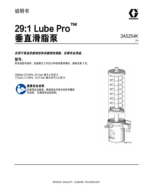
3A5254KZH说明书29:1 Lube Pro ™垂直滑脂泵仅用于泵送非腐蚀性和非磨损性滑脂。
仅限专业用途。
型号:有关的型号资料,包括最大工作压力和核准使用情况,请参见第 3 页。
3500psi (24 MPa, 241 bar) 最大工作压力175 psi (1.2 MPa, 12.07 bar) 最大空气入口压力重要安全说明在使用此设备前,请阅读本手册中的所有警告及说明。
妥善保存这些说明。
目录目录型号 . . . . . . . . . . . . . . . . . . . . . . . . . . . . . . . . . . . . . . 3警告 . . . . . . . . . . . . . . . . . . . . . . . . . . . . . . . . . . . . . . 4典型安装 . . . . . . . . . . . . . . . . . . . . . . . . . . . . . . . . . . 6安装 . . . . . . . . . . . . . . . . . . . . . . . . . . . . . . . . . . . . . . 7接地 . . . . . . . . . . . . . . . . . . . . . . . . . . . . . . . . . . . 7安装 . . . . . . . . . . . . . . . . . . . . . . . . . . . . . . . . . . . 7仅限低液位型号 . . . . . . . . . . . . . . . . . . . . . . . . . . 7DIN 连接器 . . . . . . . . . . . . . . . . . . . . . . . . . . 7空气和流体管路附件 . . . . . . . . . . . . . . . . . . . . . . 8供气管路 (U) . . . . . . . . . . . . . . . . . . . . . . . . . 8注入液箱 . . . . . . . . . . . . . . . . . . . . . . . . . . . . . . . 8填料 . . . . . . . . . . . . . . . . . . . . . . . . . . . . . . . . . . . 9供应管路 (G) . . . . . . . . . . . . . . . . . . . . . . . . . 9进给器管路(S) . . . . . . . . . . . . . . . . . . . . . . . . 9加注器 . . . . . . . . . . . . . . . . . . . . . . . . . . . . . . 9空气锁步骤 . . . . . . . . . . . . . . . . . . . . . . . . . . . . 10操作 . . . . . . . . . . . . . . . . . . . . . . . . . . . . . . . . . . . . . 11泄压步骤 . . . . . . . . . . . . . . . . . . . . . . . . . . . . . . 11泵 . . . . . . . . . . . . . . . . . . . . . . . . . . . . . . . . . . . 11起动 . . . . . . . . . . . . . . . . . . . . . . . . . . . . . . 11低液位开关 . . . . . . . . . . . . . . . . . . . . . . . . . . . . 12关机 . . . . . . . . . . . . . . . . . . . . . . . . . . . . . . . . . . 12润滑系统规模和校准指导 . . . . . . . . . . . . . . . . . 13表 1: 润滑剂输出和压力 - 美制 . . . . . . . . . . 13表 2: 润滑剂输出和压力 - 公制 . . . . . . . . . . 13维修 . . . . . . . . . . . . . . . . . . . . . . . . . . . . . . . . . . . . . 14密封件更换 . . . . . . . . . . . . . . . . . . . . . . . . . . . . 14拆卸 . . . . . . . . . . . . . . . . . . . . . . . . . . . . . . 14重新组装 . . . . . . . . . . . . . . . . . . . . . . . . . . . 19回收和弃置 . . . . . . . . . . . . . . . . . . . . . . . . . . . . . . . 24产品寿命结束 . . . . . . . . . . . . . . . . . . . . . . . . . . 24故障排除 . . . . . . . . . . . . . . . . . . . . . . . . . . . . . . . . . 25零配件 . . . . . . . . . . . . . . . . . . . . . . . . . . . . . . . . . . . 26零配件 . . . . . . . . . . . . . . . . . . . . . . . . . . . . . . . . . . . 27尺寸 . . . . . . . . . . . . . . . . . . . . . . . . . . . . . . . . . . . . . 28技术规格 . . . . . . . . . . . . . . . . . . . . . . . . . . . . . . . . . 29尺寸 美制 - 英寸(参见尺寸和布局图,第 28 页) . . . . 29尺寸 公制 - 毫米(参见尺寸和布局图,第 28 页) . . . . 29美国加州第 65 号提案 . . . . . . . . . . . . . . . . . . . . . . . 29Graco 标准保修 . . . . . . . . . . . . . . . . . . . . . . . . . . . . 3023A5254K型号型号零件号尺寸低液位正常 打开正常 关闭EU24Z051 1 磅24Z052 1 磅X X24Z053 1 磅X X24Z054 1 磅X24Z055 1 磅X X X24Z056 1 磅X X X24Z057 4 lb24Z058 4 lb X X24Z059 4 lb X X24Z060 4 lb X24Z061 4 lb X X X24Z062 4 lb X X X25V016 3 磅X X3A5254K3警告警告以下为针对本设备的设置、使用、接地、维护及修理的警告。
3A6927C ZH 安装和操作手册说明书

3A6927CZH安装和操作SDP8/SDP18 预设计量分配阀Pulse FC 已启用用于分配机油、自动变速器油液(ATF )、齿轮油和防冻液。
未获准用于爆炸性环境或危险场所。
仅适合专业用途。
有关型号信息,请参见第 6 页。
最大工作压力为 1500 磅/平方英寸(10 兆帕,103 巴)重要安全说明请在使用该设备之前,阅读本手册以及相关系统手册内所有的警告和说明内容。
妥善保存所有说明。
本计量分配阀仅设计用于分配石油基润滑油和防冻液。
刹车清洁剂和/或强腐蚀性溶剂可能会损坏塑料部件。
目录警告 (4)型号 (6)概述 (7)计量分配阀 (7)导航板(图 1) (7)锁定和解锁扳机 (7)打开和关闭喷嘴 (8)典型安装 (9)安装支架 (9)机油架 (9)安装 (10)泄压流程 (10)接地 (10)预安装步骤 (10)冲洗 (11)安装计量分配阀 (11)安装加长管 (12)安装喷嘴 (12)预设模式 (13)主菜单屏幕 (13)校准 (13)手动校准 (15)替代校准 (16)分配 (18)预设分配 (19)总计 (21)实用程序菜单 (21)设备信息 (21)重置 (22)设置屏幕 (22)设备信息 (27)重置 (27)返回 (27)Pulse FC 模式 (28)启用 Pulse FC 模式 (28)激活 (29)校准 (29)手动校准 (30)分配 (31)屏幕识别 (31)实用程序菜单 (33)维修 (35)更换电池 (35)零配件 (36)零配件 (37)相关套件 (37)故障排除 (38)故障代码 (40)技术参数 (41)FCC / IC 通知 (42)Graco 5 年流量计和阀门保修 (43)警告以下为针对本设备的设置、使用、接地、维护及修理的警告。
惊叹号标志表示一般性警告,而各种危险标志则表示与特定操作过程有关的危险。
当手册中的这些符号出现在机身上,或是警告标牌上时,请查看这些警告。
电动插桶泵使用的注意事项
☆旺泉SB系列,JK系列,YBYB系列手提式抽桶泵(油桶泵,电动抽液泵)相关文章:/xxfb/sbgx/200512/27007.html电动抽液泵是引进西德先进样研制而成,特点为超高速轴流泵,无需加引水。
本泵适用于工厂、矿山、商店、钻井队、油库、洒厂以及农村个人抽取水源之用。
本泵可提升柴油、齿轮油等石油类及各种食用油,使用全不锈钢型泵,还可用于化工企业抽吸一般酸碱液体。
上海旺泉电动抽液泵、插桶泵、防爆油桶泵JK-3B是我公司生产的手提式电动油桶泵,是集取手压油桶泵,手摇油桶泵,提油器,手动隔膜泵等吸油工具之精华。
该泵操作简便,使用省力,吸油省时,适用于各工矿企业、商店、仓库、供销社个体加油点(店),搬运站、汽车轮船等部门的吸油(工业用油、食用油)及其它液体。
本泵具有体积小、重量轻、使用灵活、经久耐用、携带方便等特点,是最经济、最实用的普及型吸油的理想工具。
如:输送饮料、低腐蚀性的水等,请选用整体不锈钢油筒泵。
YBYB-40手提式隔爆型单相油桶电泵,适用于工厂有传爆能力不高于B级,引燃温度组别不低于T4组的可燃性气体或蒸气与空气形成的爆炸性混合物的场所及一般场所从桶抽出和输送汽油、煤油、柴油、机油、食用油等腐蚀性液体,其流量为40升/分。
上海旺泉SB系列电动抽液泵:旺泉SB系列插桶泵(油桶泵,电动抽液泵)可以直接插入物料桶(最大适用于符合GB/32 5-1991标准的钢桶)中抽取桶中液体。
可输送各种油料、带腐蚀性化学药水、其他液体。
根据所输送的液体性质,泵体沾湿部分材料可选用铝合金、不锈钢, 316不锈钢等组成。
驱动电机配备单相标准电机,防爆电机,高转速屯机等多种选择。
根据材质,电机不同,型号可分为: SB-l, SB一2, SB-3,SB-3寸,SB-4,SB-5,SB-6,SB-7, SB-8系列铝合金,不锈钢或防爆型。
我们备有详细资料,欢迎索取。
旺泉该系列泵可按防爆区域和非防爆区域选用,凡在防爆区域使用配置防爆型电机,这类电机分三种机组型号,当使用条件含各种易燃易爆混合时,应选用最高组级。
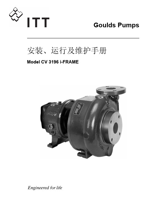
Goulds泵安装,操作和维护手册 型号CV 3196 i-FRAME说明书
变压器油泵说明书

变压器油泵使用维护说明书中华人民共和国长春诺森电机有限公司二00三年变压器油泵1.产品概述变压器油泵适用于大中型电力变压器、整流变压器、电抗器、电力机车牵引变压器及其它专用变压器的强迫油循环冷却系统中。
本公司生产的变压器油泵有QB、YB、YB2、B2、4B2、4B2、6B4、4PB、6PB、SZB、ZB等多个系列产品,是国内最早生产变压器油泵产品的公司,品种最多,规格型号最全。
我公司是该类产品多项国家行业标准的主要起草和实验单位。
上述产品系列中,在设计结构、工艺、材料方面各有特点,6B4系列为我公司最新推出的低转速、高效率、高可靠性、高技术含量的新一代专利产品,可完全替代国内现有的各种型号规格,蜗壳采用拉伸新工艺,外型美观,确保无渗漏,受到用户一致好评。
2.型号说明□ B □□—□/ □□□环境代号W ——一般地区,可省略TH——湿热带TA——干热带安装代号 B ——卧式安装V ——立式安装电机功率(kW)扬程(m)流量(m3/h)设计序号变压器油泵电机极数3 使用条件3.1 环境温度:-30℃~50℃3.2 输送液体:变压器油3.3 变压器油泵入口油温最高:95℃,最低:高于变压器油凝固点5℃。
3.4 电源为三相交流电,额定电压为380V,额定频率为50Hz。
3.5 工作方式:连续运行。
3.6 油泵轴承在正常使用维护保养条件下,运转寿命至少5年。
4. 产品型号及技术参数(见附表一)5.安装使用维护5.1 外形及安装尺寸(见附表二与附图)5.2使用5.2.1 检查电机定子绕组热态绝缘电阻,用500V兆欧表测量时,不低于1MΩ。
5.2.2 叶轮旋转方向由接线盒端子U、V、W与电源A、B、C对应关系决定,相对应时,为正方向。
5.2.3 在进油口处拨动叶轮,转动应轻快灵活,如有停滞或磨擦现象,必须校正叶轮偏摆,其两密封环直径处圆跳动应不超过0.1mm。
5.2.4 油泵在空载状态下运行,应在进油口注入少量变压器油,保证轴承的润滑作用,试验时间不得超过5分钟,运转时声音应均匀和谐,无杂音。
ACCU-LUBE-安装操作使用指南

Accu-Lube
Environmentally Safe Lubricants and Micro-Lubrication Systems for Near-Dry Machining
Precision Lubricant Applicator
精密润滑喷油机
Installation and Operating Instructions 安装操作使用指南
4. 准备使用. . . . . . . . . . . . . . . . . . . . . . . . . . . . . . . . . . . . . . . . . . . . . . . . . . . . 4
5. 安装给油机. . . . . . . . . . . . . . . . . . . . . . . . . . . . . . . . . . . . . . . . . . . . . . . . . . .5
开箱检验
当您打开新的 Accu-Lube 供油润滑系统时请确认包括以下部件: 1. Accu-Lube 给机油 2.油罐 3.空气过滤器 4.样品油 5.喷头及紧固件 6.喷嘴 7.保修卡 8.调查表
客户服务
如果出现破损,建议立即联系承运商。如果缺少零部件,请联系 ITW ROCOL North America 的中国服务供应商。
ITW ROCOLTM North America 中国服务商 上海曼斯实业有限公司
上海市松江车墩松江工业区泖亭路 188 号 29-104 栋 电话:86-021-37620505/06/07 传真:86-021-37620508 邮箱:mansi@
但是使用ACCU-LUBE以外的油品或者非正常工艺及工况而出现的问题,由购买者自己 负责。
国家特斯普尔公司1213R电动润滑油泵产品说明书

National-Spencer Inc.Model 1213RIncluded Accessories:1559A-ASSYAir Regulator1536AControl Handle120-SDrum Dolly1545“Z” Swivel 65385Drum Cover1524Follower Plate18066’ Grease Hose 20044’ Air Hose Product Specifications:Part #1213RPumpHeavy-Duty 65:1 RatioMax Grease NLGI No. 3Max. Delivery 66-oz per minute @ 90PSIMax. Air PSI 110 PSIAir Consumption8.74 CFM @ 100 PSIAir Inlet 1/4" NPT Air Hose1/4" x 4-ft (2004)Pump Head Dia. 2 1/2" Head Length 10"Tube Length 29"Pump Tube Diameter 1 3/16"Air Line Filter Package1559A-ASSYDescription:The 1213R Greasing System was designed as acomplete solution for dispensing grease from a 120lb. drum. The 65:1 pneumatic pump is powerful enough to handle most grease, up to No. 3 NLGI. The 1536A control handle is capable of boosting the output pres-sure to 10,000 psi, making it the ideal choice for a backed up grease fitting.Pneumatic Pump1213RARIMPORTANT NOTEFOR REASONS OF SAFETY AND PRODUCT INTEGRITY, THE OPERATOR MUST RESTRICT HIMSELF TO ORDINARY MAINTENANCE (FILTERS, SILENCERS, CLEANING...) WHEREAS FOR ANY INTERVENTIONS OF EXTRA- ORDINARY MAINTENANCE OR REPAIR, ALWAYS CON-TACT OUR SALES AND SERVICE CENTRES.STARTING UPFig. 1 - Fit a tube for compressed air to the air intake reduction A of the air-operated pump, by means of 1/4" threaded fittings G.The compressed air supply must not exceed 8 bar.GREASE DELIVERY TUBEFig. 1 - Before connecting the grease delivery tube C (supplied on request), to the liquid outlet reduction of the air- operated pump, operate the pump for 20-30 secs. max. so that the grease comes out of the same.DIFFICULT SUCTIONIf grease delivery is not obtained (formation of air pockets) it is advisable to lift the air- operat-ed pump ( g. 2) and pour 200-300 cc of SAE 40 oil in the suction zone of the same in order to eliminate the suction of air. This operation is nearly always necessary when the grease used is not of the self- levelling type, the diaphragm is not used and the grease has been hardened by the cold.As soon as the grease comes out the pump, connect tube A ( g. 3) and, at the end of the tube, gun B supplied on request. Operate the pump by keeping the delivery gun open until grease comes out. If the grease fails to come out, check the tube and gun.GREASE DIAPHRAGM ( g. 4)For regular, trouble-free operation, we always recommend application of the grease diaphragm M, especially when self-levelling greases are not used. The diaphragm, which is pulled towards the bottom of the drum by suction pressure caused by the air-operated pump, compresses the grease, preventing the formation of air pockets which could cause a blockage in delivery. Always keeping the grease clean will preserve its characteristics and also enable the grease, which without a diaphragm would otherwise remain stuck to the walls of the drum, to be collected from the bottom and almost totally drawn.FORCED LUBRICATIONThe condensation in compressed air can slow down and even block the motor cylinder; in order to prevent this from happening, every now and again operate the aeropulsometer for a couple of minutes after having let in, from the air inlet hole, 50 grams of vaseline oil, or in any case, another very uid oil. If necessary, repeat thisoperation until the motor is perfectly lubricated.FILTER CLEANINGIn the event of poor or slow grease delivery, check thestate of lters A - B - C.TRANSPORT AND HANDLING The air-operated grease pumps are supplied packed, assembled and ready to us. Do not disperse the container in the environment. No special attention is needed when handling and packing new air- operated pumps.National-Spencer Inc.1213RAR Operating Guide。
立桩油泵SDV15和XDV20油泵放油阀说明书

Instructions-Parts ListSDV15 and XDV20 Dispense Valve312789H- For non-metered dispensing of petroleum and synthetic-based oil - Models: Pages 2 and 31500 psi (10 MPa, 103.4 bar) Maximum Working PressureTI1466aSDV15 Model ShownENModelsModelsSDV15 Dispense Valve ModelsAll models include: 1/2 npt(f) swivel with locking-open triggerPart No.Extension Nozzles Fluid Type247712Rigid Automatic non-drip, quick close Oil247713Flexible Automatic non-drip, quick close Oil247714Gear Lube Automatic, non-drip, quick close Gear Lube247715Rigid Automatic, non-drip, quick close Anti-freeze247716Flexible Automatic, non-drip, quick close Anti-freeze247717NONE NONE AllAll models include: 1/2 - 14 BSPP swivel with locking-open triggerPart No.Extension Nozzles Fluid Type24H384Rigid Automatic non-drip, quick close Oil24H385Flexible Automatic non-drip, quick close Oil24H386Gear Lube Automatic, non-drip, quick close Gear Lube24H387Rigid Automatic, non-drip, quick close Anti-freeze24H388Flexible Automatic, non-drip, quick close Anti-freeze24H389NONE NONE AllAll models include: 1/2 - 14 BSPT swivel with locking-open triggerPart No.Extension Nozzles Fluid Type24H390Rigid Automatic non-drip, quick close Oil24H391Flexible Automatic non-drip, quick close Oil24H392Gear Lube Automatic, non-drip, quick close Gear Lube24H393Rigid Automatic, non-drip, quick close Anti-freeze24H394Flexible Automatic, non-drip, quick close Anti-freeze24H395NONE NONE All2312789HModelsXDV20 Non-metered Valve ModelsNPT Models - All models include locking-open and closed triggerPart No.Swivel Extension Nozzles Fluid Type 2477181/2” npt (f)Rigid High flow, non-drip, quick close Oil / Anti-freeze 2477211/2” npt (f)Flexible High flow, non-drip, quick-close Oil / Anti-freeze 2477223/4“ npt (f)Rigid High flow, non-drip, quck close Oil / Anti-freeze 2477233/4” npt (f)Flexible High flow, non-drip, quick close Oil / Anti-freeze 2477241/2” npt (f)NONE NONE Oil / Anti-freeze 2477253/4” npt (f)NONE NONE Oil / Anti-freezeBSPP Models - All models include locking-open and closed triggerPart No.Swivel Extension Nozzles Fluid Type 24H4071/2” - 14 BSPP Rigid High flow, non-drip, quick close Oil / Anti-freeze 24H4081/2” - 14 BSPP Flexible High flow, non-drip, quick-close Oil / Anti-freeze 24H4093/4“- 14 BSPP Rigid High flow, non-drip, quck close Oil / Anti-freeze 24H4103/4” - 14 BSPP Flexible High flow, non-drip, quick close Oil / Anti-freeze 24H4111/2” - 14 BSPP NONE NONE Oil / Anti-freeze 24H4123/4” - 14 BSPP NONE NONE Oil / Anti-freezeBSPT Models - All models include locking-open and closed triggerPart No.Swivel Extension Nozzles Fluid Type 24H4131/2” - 14 BSPT Rigid High flow, non-drip, quick close Oil / Anti-freeze 24H4141/2” - 14 BSPT Flexible High flow, non-drip, quick-close Oil / Anti-freeze 24H4153/4“ - 14 BSPT Rigid High flow, non-drip, quck close Oil / Anti-freeze 24H4163/4” - 14 BSPT Flexible High flow, non-drip, quick close Oil / Anti-freeze 24H4171/2”- 14 BSPT NONE NONE Oil / Anti-freeze 24H4183/4” - 14 BSPT NONE NONE Oil / Anti-freeze312789H3WarningsWarningsThe following warnings are for the setup, use, grounding, maintenance, and repair of this equipment. The exclama-tion point symbol alerts you to a general warning and the hazard symbol refers to procedure-specific risk. Refer back to these warnings. Additional, product-specific warnings may be found throughout the body of this manual where applicable.4312789HInstallation312789H 5InstallationGroundingThe equipment must be grounded. Grounding reduces the risk of static and electric shock by providing an escape wire for the electrical current due to static build up or in the event of a short circuit.Pump: follow manufacturer’s recommendations.Air and fluid hoses: use only grounded hoses. Air compressor: follow manufacturer’s recommenda-tions.Fluid supply container: follow local code.To maintain grounding continuity when flushing or reliev-ing pressure , always hold metal part of valve firmly to side of grounded metal pail, then trigger valve.Pressure Relief Procedure1.Turn off power supply to pump.2.Trigger valve into waste container to relieve pres-sure.3.Open any bleeder-type air valves and fluid drainvalves in the system.4.Leave drain valve open until you are ready to pres-surize the system.If you suspect the spray tip or hose is clogged or that pressure has not been fully relieved after following the steps above, VERY SLOWLY loosen tip guard retaining nut or hose end coupling to relieve pressure gradually, then loosen completely. Clear hose or tip obstruction.Pre-Installation Procedure1.Relieve pressure as described in Pressure ReliefProcedure.2.Close fluid shut-off valve (A, F IG . 1).3.Ground hose, reel and console (See Grounding ).NOTICEDo not use PTFE tape on pipe joints; it may cause aloss of ground across the pipe joint.The equipment stays pressurized until pressure is manually relieved. To reduce the risk of serious injury from pressurized fluid, accidental spray from the dis-pense valve or splashing fluid, follow this Pressure Relief procedure whenever you:•Are instructed to relieve pressure•Check, clean or service any system component •Install or clean fluid nozzlesInstallation6312789HTypical InstallationF IG . 1 shows a typical installation. The installation is only a guide. The components shown are typical; however, it is not a complete system design. Contact your Graco distributor for assistance in designing a system to suit your particular needs.Dispense valves can also be installed on a console.Installation Procedure1.Relieve pressure , page 5.Steps 2 - 6 are the Flushing Procedure.2.Close fluid shut-off valve (A) at each dispense posi-tion.3.Make sure main fluid outlet valve at pump is closed,the air pressure to the pump motor is adjusted, and the air valve is open. Slowly open main fluid valve.4.Place hose end (with no dispense valve connected)into a container of waste oil. Secure hose in con-tainer so it will not come out during flushing. If you have multiple dispense positions, flush the dispense position farthest from pump first and work your way toward the pump.5.Slowly open fluid shut off valve (A) at dispense posi-tion. Flush out a sufficient amount of oil to ensure the entire system is clean. Close valve.6.Repeat Step 5 for all dispense positions.•Do not use this dispense valve on non-Graco con-soles. Such use could result in trigger becoming inadvertently pressed while valve is stowed.•To prevent line contamination, which can cause equipment damage or malfunction, flush the lines before your install the equipment in the system.F IGIf this is a new installation, or if the lines are contami-nated, flush the lines before you install dispensing valve.Key DescriptionA Fluid shutoff valveBHoseC Hose reel fluid inlet hoseD Hose reel EDispense valveA Thermal Relief Kit (not shown) is required.The Kit required will vary by pump selected. See Parts, page 16 for a list of available kits.Operation312789H 7Existing Installation1.Relieve pressure , page 5.2.Loosen and disconnect hose from old dispensevalve (the one you are replacing).Existing or New InstallationFor Steps 3 - 5 see F IG . 2.3.Thread extension (11) into outlet of the dispensevalve handle (1). Tighten securely.4.Apply thread sealant to male threads of hose fitting.Thread hose fitting into swivel (6). Tighten firmly.5.Thread nozzle (12) or nozzle adapter onto extensionand tighten firmly.6.Open all dispense position shut-off valves. Startpump to pressurize system.OperationFor part numbers referenced in these instructions, see Parts, page 10.Dispensing Procedure1.Open (or unlock) nozzle.2.Pull trigger (15) toward the valve handle (1) to openvalve and begin dispensing.3.Lock valve open by keeping trigger (15) squeezedand depressing trigger lock button (14). Then you can release trigger.4.To release trigger lock (14), pull trigger (15) towardvalve handle (1). 5.Release trigger (15) to stop dispensing.6.Close (lock) nozzle.•Do not overtighten extension.•Thread extension in at least three full turns. Position extension for proper alignment with valve handle (1) and tighten nut (11a).F IG. 2611a11121ti11466aTo reduce the risk of a serious bodily injury, including fluid injection, never exceed the maximum working pressure of the valve you are using or of the lowest rated component in your system.The XDV20 dispense valve trigger automatically locks whenever you release the trigger and must be unlocked each time you begin a new dispense.Troubleshooting8312789HTroubleshootingRelieve pressure before you check or repair dispense valve. Be sure all other valves and controls and the pump are operating properly.*Some fluid seepage is possible in applications where thermal expansion of fluid is possible.ProblemCauseSolutionSlow or no fluid flowScreen is clogged 1.Relieve pressure.2.Clean or replace strainer (4a)and washer 4b. Order Filter Kit 256164.3.If the problem remains, contactyour Graco distributor for repair or replacement.Pump pressure is low Shutoff valve is not full openOil leaks from swivel Swivel is looseTorque the swivel (6) to 15-20 ft-lb (20-27 N.m).If the problem remains, contact your Graco distributor for repair or replacement.O-ring is worn or damagedReplace swivel (6). Torque swivel to 15-20 ft-lb (20-27 N.m).If the problem remains, contact your Graco distributor for repair or replacement.Oil drips from nozzle*Nozzle is damaged or obstructed Inspect nozzle for damage or obstructions. Replace if damaged.Valve leaksO-rings or valve seat are worn or damagedReplace seals (9) and/or valve seat (2).Service312789H 9ServiceValve Handle Repair1.Relieve pressure , page 5.2.If you are replacing the seals (9), the cam (8) or thepush rod (3), remove the swivel (6) and remove the internal pieces. You must remove the cam in order to get the push rod out of the valve end.3.Remove screws (7) and washers (10) and removetrigger (15). 4.Push cam (8) out of valve handle (1). 5.Replace seals (9) and/or cam (8).6.Replace any worn or broken parts.7.Reassembly internal parts. Refer to F IG . 3 for cor-rect installation order and orientation of parts.8.Lubricate the cam (8) and slide it into the valve han-dle (1), making sure the notch is oriented as shown in F IG . 3, with the large end of the push rod (3) rest-ing in the notch of the cam.9.Replace the screws (7) and seals (9). Torquescrews to 15 -25 in-lb (1.7 to 2.8 N•m).10.Replace swivel (6). Torque to15-20 ft-lb (20-27N.m).Filter ReplacementOrder Filter Kit 256164.1.Relieve pressure, page 5.2.Unscrew hose fitting from swivel (6).3.Remove swivel (6) from valve handle (1).4.Remove strainer (4a) and washer (4b) from inside ofswivel (6).5.Replace washer (4b) and strainer (4a). Refer to F IG .4 to ensure correct orientation of filter in swivel.6.Thread hose fitting into swivel (6) and tighten.Torque swivel to 15-20 ft-lb (20-27 N.m).The large end of the push rod (3) fits into a notch in the cam (8) which is part of the trigger assembly. It is important you know this before you remove orinstall parts.The push rod (3) must be inserted through the out-let end of the valve handle before cam (8) is installed.F IG . 36173891015ti12073a710F IG . 4ti12074a14b 4a6Parts10312789HPartsSDV15 Dispense ValvesFN Part No.DescriptionQty 1HANDLE, valve, standard duty12191313SEAT, valve 13277673ROD, push14256164KIT, filter, includes 4a and 4b14a STRAINER104b WASHER, plain106238399SWIVEL, straight, NPT 124H382SWIVEL, straight, BSPP 124H383SWIVEL, straight, BSPT17110637SCREW, machine, pan head 28191315CAM19113574SEAL, quad ring 210191552WASHER, flat 211*KIT, nozzle and extension, page 12112*113113924SPRING, compression 11415R526LOCK, trigger 115191320TRIGGER 116192106GUIDE, spring 118113493SPRING, compression 120†172479TAG, warning 12215K672ADAPTER, o-ring, model 247714125†290180TAG, caution 1*These parts are not included on model 247717† Not shownFN Part No.Description Qty ti11467b64b4a18271013111215161413910781112111222Torque to 15-20 ft. lbs (20-27 112Torque to 15 - 25 in. lbs (1.7- 2.8 N•m)22Parts312789H 11PartsXDV20 Non-metered ValvesFN Part No.Description Qty1HANDLE, valve, medium duty 1215U704SEAT, valve 13277673ROD, push 14256164KIT, filter, includes 4a and 4b 14a STRAINER 104b WASHER, plain 106247344SWIVEL, straight, 1/2 NPT models 247718, 247721, 247724124H097SWIVEL, straight, 1/2 BSPT, mod-els 24H413, 24H414, 24H417124H098SWIVEL, straight, 1/2 BSPP, mod-els 24H407, 24H408, 24H411247345SWIVEL, straight, 3/4 NPT models247722, 247723, 24772524H099SWIVEL, straight, 3/4 BSPT, mod-els 24H415, 24H416, 24H418124H100SWIVEL, straight, 3/4 BSPP, mod-els 24H409, 24H410, 24H4127110637SCREW, machine, pan head 28191315CAM 19113574SEAL, quad ring 210191552WASHER, flat 211*KIT, nozzle and extension, page 12112*113114680PIN, dowel 11415R016LATCH, pin 11515M886TRIGGER 11615R015LATCH, arm 11715R014LATCH, spring 11815R013LATCH, lever 120113493SPRING, compression 122†172479TAG, warning 12415U700PLUNGER, trigger, lift 12515U701SPRING, secondary 126†290180TAG, caution 1* These parts are not included on models 247724 or247725† Not shownFNPart No.Description Qty ti12076a664b4a20217103121111710989171613181415Torque to 15-20 ft. lbs (20-27 1Torque to 15- 25 in. lbs (1.7- 2.8 N•m)222112524Parts12312789HSDV15 Nozzle Extension KitsPart No.DescriptionFluid Type*illustration note255852*Automatic, non-drip quick close nozzle with rigid extension.Oil255853*Automatic, non-drip quick close nozzle with flexible extensionOil255854Non-drip, quick close nozzle with rigid exten-sionGear Lube*Used for dispensing 5gpm (22.7 lpm) or less.continuedti11826ti11827ti11825ti11827ti11831ti11830ti12078aParts312789H 13255855*Non-drip, quick close nozzle with rigid exten-sionAnti-freeze255856*Non-drip, quick close nozzle with flexible extensionAnti-freeze255857Non-drip, quick close, high-flow nozzle with rigid extension Oil and Anti-freeze255858Non-drip, quick close, high flow nozzle with flexible extension Oil and Anti-freeze*Used for dispensing 5gpm (22.7 lpm) or less.Part No.Description Fluid Type*illustration noteti11826ti11828ti11825ti11828ti11826ti11829ti11825ti11829Parts14312789HSDV15 Nozzle KitsPart No.DescriptionQtyFluid Type255459*Automatic, non-drip, quick-close nozzle Oil• BODY, nozzle 1• O-RING, packing 1• SPRING, compression 1• O-RING, packing 1• STEM, nozzle, valve 1• SEAT, valve1255460*Automatic, non-drip, quick-close nozzle Anti-freeze• BODY, nozzle1• SPRING, compression 1• O-RING, packing 1• STEM, nozzle, valve,1• O-RING, packing 1• SEAT, valve1255461Automatic, non-drip, high-flow nozzle Oil and Anti-freezea • STEM, nozzle, qty 1b • BODY, nozzle, qty 1c • O-RING, packing, qty1d • O-RING, packing, qty 1e • O-RING, packing, qty 1255470Non-drip, quick-close nozzle Gear Lube • Housing 1• Body, nozzle 1• O-RING, packing 1• O-RING, packing,1• Plug, Hollow, hex1*Used for dispensing 5gpm (22.7 lpm) or less.Parts312789H 15XDV20 Nozzle Extension KitsXDV20 Nozzle KitsPart No.DescriptionFluid Type*illustration note255921Non-drip quick close,high flow nozzle with rigid extension. Oil and Anti-freeze255859Non-drip quick close, high flow nozzle with flexible extension.Oil and Anti-freezeti12680ati12679aPart No.DescriptionQtyFluid Type255793Non-drip, quick close, high flow nozzle Oil and Anti-freeze• O-RING, packing 1• O-RING, packing 1• BODY, nozzle, high flow 1• O-RING, packing1• STEM, nozzle, heavy duty1Technical Data16312789HThermal Relief KitsTechnical DataPart No.DescriptionPSI (bar) Rating 112353Diaphragm pump for fuel dispense, valve only 50 psi (3.4 bar)235998Mini Fire-Ball ™ 225, 3:1 600 psi (41 bar)237601Fire-Ball 425, 3:1600 psi (41 bar)237893Fire-Ball 300, 5:1 and Fire-Ball 425, 6:1 900 psi (62 bar)248296Fire-Ball 300, 5:1 and Fire-Ball 425, 6:1 (same as 237893 minus bung adapter and swivel. Includes 6-foot hose)900 psi (62 bar)238899Diaphragm pump 150 psi (10.4 bar)240429Fire-Ball 425, 10:11600 psi (110 bar)248324Fire-Ball 425, 10:1 (same as 240429 minus bung adapter and swivel. Includes 6-foot hose)1600 psi (110 bar)Maximum Flow RangeSDV1515 gpm (56.8 lpm)XDV2020 gpm (75 lpm)Maximum Working Pressure SDV15/XDV201500 psi (102 bar)SDV15/XDV20 Weight 0.4 lbs (0.18 kg)Inlet See pages 2 and 3 for models and configuration information OutletSDV153/4 - 16 straight thread o-ring boss XDV207/8 - 14 straight thread o-ring Operating temperature range -40°F to 180°F (-40°C to 82°C)Wetted partsAluminum, Stainless Steel, CS, Acetal, Nitrile Rubber, TPE Fluid compatibilityAntifreeze, gear lube, oilNotes Notes312789H17All written and visual data contained in this document reflects the latest product information available at the time of publication.Graco reserves the right to make changes at any time without notice.Original instructions. This manual contains English. MM 312789For patents see: /patentsGraco Headquarters: MinneapolisInternational Offices: Belgium, China, Japan, Korea GRACO INC. P.O. BOX 1441 MINNEAPOLIS, MN 55440-1441Copyright 2008, Graco Inc. is registered to I.S. EN ISO 90015/2008, Revised November 2018Graco 7-Year Meter and Valve WarrantyGraco warrants all equipment referenced in this document which is manufactured by Graco and bearing its name to be free from defects in material and workmanship on the date of sale to the original purchaser for use. With the exception of any special, extended, or limited warranty published by Graco, Graco will, for a period from the date of sale as defined in the table below, repair or replace equipment covered by this warranty and determined by Graco to be defective. This warranty applies only when the equipment is installed, operated and maintained in accordance with Graco’s written recommendations.This warranty does not cover, and Graco shall not be liable for general wear and tear, or any malfunction, damage or wear caused by faulty installation, misapplication, abrasion, corrosion, inadequate or improper maintenance, negligence, accident, tampering, or substitution ofnon-Graco component parts. Nor shall Graco be liable for malfunction, damage or wear caused by the incompatibility of Graco equipment with structures, accessories, equipment or materials not supplied by Graco, or the improper design, manufacture, installation, operation or maintenance of structures, accessories, equipment or materials not supplied by Graco.This warranty is conditioned upon the prepaid return of the equipment claimed to be defective to an authorized Graco distributor for verification of the claimed defect. If the claimed defect is verified, Graco will repair or replace free of charge any defective parts. The equipment will be returned to the original purchaser transportation prepaid. If inspection of the equipment does not disclose any defect in material or workmanship, repairs will be made at a reasonable charge, which charges may include the costs of parts, labor, and transportation.THIS WARRANTY IS EXCLUSIVE, AND IS IN LIEU OF ANY OTHER WARRANTIES, EXPRESS OR IMPLIED, INCLUDING BUT NOT LIMITED TO WARRANTY OF MERCHANTABILITY OR WARRANTY OF FITNESS FOR A PARTICULAR PURPOSE .Graco’s sole obligation and buyer’s sole remedy for any breach of warranty shall be as set forth above. The buyer agrees that no other remedy (including, but not limited to, incidental or consequential damages for lost profits, lost sales, injury to person or property, or any other incidental or consequential loss) shall be available. Any action for breach of warranty must be brought within one (1) year past the warranty period, or two (2) years for all other parts.GRACO MAKES NO WARRANTY, AND DISCLAIMS ALL IMPLIED WARRANTIES OF MERCHANTABILITY AND FITNESS FOR A PARTICULAR PURPOSE, IN CONNECTION WITH ACCESSORIES, EQUIPMENT, MATERIALS OR COMPONENTS SOLD BUT NOTMANUFACTURED BY GRACO . These items sold, but not manufactured by Graco (such as electric motors, switches, hose, etc.), are subject to the warranty, if any, of their manufacturer. Graco will provide purchaser with reasonable assistance in making any claim for breach of these warranties.In no event will Graco be liable for indirect, incidental, special or consequential damages resulting from Graco supplying equipment hereunder, or the furnishing, performance, or use of any products or other goods sold hereto, whether due to a breach of contract, breach of warranty, the negligence of Graco, or otherwise.Graco InformationTO PLACE AN ORDER, contact your Graco distributor or call to identify the nearest distributor.Phone: 612-623-6928 or Toll Free: 1-800-533-9655, Fax: 612-378-3590Graco 7-Year Meter and Valve Extended WarrantyComponentsWarranty PeriodStructural Components 7 years Electronics3 years Wear Parts - including but not limited to o-rings, seals and valves1 year。
- 1、下载文档前请自行甄别文档内容的完整性,平台不提供额外的编辑、内容补充、找答案等附加服务。
- 2、"仅部分预览"的文档,不可在线预览部分如存在完整性等问题,可反馈申请退款(可完整预览的文档不适用该条件!)。
- 3、如文档侵犯您的权益,请联系客服反馈,我们会尽快为您处理(人工客服工作时间:9:00-18:30)。
69
HVDP40 316SS
51
102
HVDP48
122
注:其他密封可选
密封 石墨 陶瓷 Viton
石墨
陶瓷 Viton 石墨 陶瓷 Viton
60
9
注:当输送易燃易爆的介质时,请使用配防爆电机或气动马达的不锈钢泵管,泵管上安装静电保护装置。 +气动马达不以电作为动力,这样减少了易燃的可能性。
6
中低等粘度桶泵
TB 系列
TB 系列重量轻,适用于低粘度的介质。特别适合小口径的容
器。
特点
z 机械密封 z 独特的单级增压叶轮 z 不锈钢结构
性能参数
注:以上参数以水为介质 5
中等粘度溶剂桶泵
TT系列
泵管
型号 材质 TTS 316SS STTS 316SS
直径(mm) 38
长度(cm) 69 102
122
38
102
69
密封
石墨填 PTFE
泵轴 316SS 316SS
内部组件 PTFE
TTC CPVC
41
102
哈氏合金
122 STTS 满足 USDA 要求,可以使用在食品/卫生级要求的场合。
了成本。是市场上最经济的桶泵。为代替手泵和笨 拙的气动隔膜泵而设计,重量轻,易于操作。抗腐 蚀的PP泵管并配备电机或气动马达,EP系列可使 用在间歇式应用的场合,输送化学品的领域。
泵管特点
z 价格经济 z 耐腐蚀的PP材质泵管 z 轻便便携,重量仅2.3公斤 z 间歇式工作 z 坚固的结构适合工业应用
美国FTI桶泵产品系列全,能满足并解 决工业生产过程中遇到取料,卸料,加料和 清桶(槽)等问题,使您的取料,卸料,加 料和清桶(槽)变得安全,高效和便利,避 免了浪费和环境污染等问题
美国 FTI 公司真诚为广大客户在桶泵 方面提供专业服务!
未使用桶泵
使用桶泵后
经济便携性实验室用泵
EP系列
EP系列经济型泵,提高了劳动效率,节约
z 最大比重:1.4 z 最高温度:66℃ z 最大流量:电动 75.7lpm / 气动 56.8lpm z 最大扬程:电动 8.6m / 气动 5m z 最大粘度:200cps
注:以上参数以水为介质 7
中低等粘度桶泵
泵管
型号
材质
直径(mm) 长度(cm) 密封
TB 系列
泵轴
内部组件
软管口径(mm)
z 最大粘度:HR型20000cps,LR型100,000cP
典型应用
z 化学l:粘合剂,粘性流体,原油,油脂。 z 化妆品:肥皂,面团,香波,面霜 z 食品:蜂蜜,糖浆,番茄浆 z 衣服:染料,漆,蜡
性能曲线:
13
高粘度螺杆型桶泵
HVDP 系列
泵管
型号
材质 直径(mm) 长度(cm)
HVDP27
特点
z 无泄露设计 z 独特双吸叶轮设计 z 3种泵管材质,多种马达供选择 z 易拆卸,便于清洗 z 一定的空转能力 z 防碰撞设计
性能参数
z 最大比重:1.83 z 最高温度:PFP-71℃,PFV-49℃,PFS-105℃ z 最大流量:电动151lpm / 气动83lpm z 最高扬程:电动24m / 气动11.6m z 最高粘度:电动2000cps / 气动330cps
10000
22.7
电源要求
功率
转速
最大流量 lpm
370W 300-6000
22.7
最大扬程 m 3.7
最大扬程 m 3.7
2
高性能无泄露桶泵
PF系列
PF系列高性能无泄露桶泵,能满足并解决大多数工业
生产过程中遇到取料,卸料,加料和清桶(槽)等问题,使 您的取料,卸料,加料和清桶(槽)变得安全,高效和便利, 避免了浪费和环境污染等问题。
公司简介
美国菲尼斯汤普森股份有限公司 (FINISH THOMPSON INC.,FTI)致力于 设计和制造磁力离心泵,工业用桶泵,溶剂 和引擎冷却液回收机及冷却液变换器。FTI 产品在美国宾夕法尼亚州伊利市制造,通过 世界各地的存货商在全球销售。
美国FTI公司具有30多年专业生产工 业用桶泵的历史,是全球三大桶泵生产商之 一,美国桶泵市场占有量位居第一。
20
石墨填 PTFE
PP, PTFE Viton, PVDF
102
哈氏合金
20
电动马达
型号
类型
防溅, M54 IP44,双绝
缘
注:可以提供 110/60Hz 电机
气动马达
型号
类型
认证 CE 认证
M57
气动
CE
注:不能输送易燃介质或在危险场所使用
电源要求 220V50HZ
功率 100W
转速
最大流量 lpm
认证 CE
电源要求 功率
转速 最大流量 lpm 最大扬程 m
370w 300-6000
83
11.6
M6X
气动+
CE
560w 300-3000
55
3.5
注:当输送易燃易爆的介质时,请使用配防爆电机或气动马达的不锈钢泵管,泵管上安装静电保护装置
*建议在防爆环境下输送非易燃性介质 +气动马达不以电作为动力,这样减少了易燃的可能性
TBS
316SS
38
102
石墨填 PTFE
316SS
PTFE
25
Viton○R 氟橡胶为美国杜邦公司注册商标 Tefzelr○R 含氟橡胶为美国杜邦 E.I.公司注册商标
电动马达
型号 M5 M5T
类型 防溅,IP44 TEFC,IP54
认证 CE CE
电源要求 220V50HZ 220V50HZ
功率 370w 370w
47.3
5.8
M6X
气动+
CE
560w 300-3000
47.3
5.8
注:当输送易燃易爆的介质时,请使用配防爆电机或气动马达的不锈钢泵管,泵管上安装静电保护装置。
*建议在防爆环境下输送非易燃性介质。 +气动马达不以电作为动力,这样减少了易燃的可能性。
10
高粘度桶泵
BT系列
BT系列为高扬程高粘度中等腐性易燃性介质而设计。用于输送聚
注:使用防爆电机时流量不得超过26lpm,扬程不超过6m。这样可减 少静电。
3
高性能无泄露桶泵
PF系列
泵管
型号 材质 直径(mm) 长度(cm) 密封 泵轴
PFP
PP
PFV PVDF
51
PFS 316SS
哈氏合 金
69
102
无泄 哈氏合
122
露设
金
152
计
183
316SS
Viton○R 氟橡胶为美国杜邦公司注册商标 Tefzelr○R 含氟胶为美国杜邦 E.I.公司注册商标
9
中低等粘度漂白领域桶泵
泵管
型号
材质
直径(mm)
长度(cm)
TBP 系列
密封
泵轴
内部组件
软管口径(mm)
纯
石墨填
TBP
PP/PVDF
38
102
PTFE
316SS
PTFE
25
电动马达
型号 M5 M5T
类型
防溅,IP44 TEFC, IP54
认证 CE CE
M10X* 防爆,IP54
CE,EX DEMKO
内部组件
PP PTFE PVDF Viton○R PTFE PVDF Viton○R 316SS PTFE Tefzelr○R Viton○R
软管口径(mm) 25
电动马达
型号 M5 M5T
M10X*
类型 防溅,IP44 TEFC,IP54
防爆,IP54
认证
CE CE CE,EX DEMKO TUV
12
高粘度螺杆型桶泵
HVDP 系列
特点
z 螺杆式叶轮 z 粘度最大20,000cP z 泵管316SS z 16:1齿轮减速 z .配800w调速电机 z 机械密封或填料密封 z 易于拆卸便于清洗
性能参数
z 最大流量:32lpm z 最大扬程:91m z 最大工作压力:8bar z 最高温度:82℃
316SS
PTFE
25/40
电动马达 电动马达
型号 M39 M40 M50
型号 M18
类型 TEFC TEFC TEFC
类型 气动
认证 CSA,UL CSA,UL CSA,UL
认证
电源要求 220/380v50hz 220/380v50hz 220/380v50hz
功率 800w 1500w 1100w
合体,粘合剂,原油,树脂等等。
特点
z 机械密封 z 易于拆卸,便于清洗
性能参数
z 最大粘度15000cps z 最大流量38lpm z 最大扬程61m z 最高温度 93℃
11
高粘度桶泵
泵管
型号
材质
直径(mm) 长度(cm)
密封
BT系列
泵轴
内部组件
软管口径(mm)
BTS
316SS
51
102
石墨填 PTFE
转速 10000 10000
最大流量 lpm 75.7 75.7
CE,EX
M10X* 防爆,IP54
DEMKO
220V50HZ 370w 10000
75.7
TUV
最大扬程 m 8.5 8.5
8.5
气动马达
型号 M6
类型 气动+