高精度七位半数字万用表 PREMA 5017
8位半万用表大比拼
的精密数字仪表生产厂家,代表产品为万用表。
天水长城电工仪器厂曾组装生产过其5000,6000系列5位半,6位半,以及5017 7位半万用表。
由于引进的早现国内仍有使用。
网上关于Prema 6048的介绍很少,以下链接有比较详细的介绍。
不过可惜的是,prema目前已退出测试测量市场,关注于模拟IC和混合信号ASIC和ASSP 市场,网站。
也就是说目前市场上流通的prema万用表均为二手。
图6 Prema 6408Agilent在很早之前就推出了8位半万用表3458A,一推出就以其无与伦比的稳定性和高速测量成为实验室的传递标准,这个情况一直持续到2002年Fluke推出8508A。
但其的积分线性、的微分线性(类似No missing code)指标,目前还是无人能比。
图7 Agilent 3458AKeithely后来也推出了8位半万用表2002,这款仪表的突出优势在于直流电压档跟它的很多纳伏表一样具有1nV的灵敏度,电阻档具有100nOhm的灵敏度,以及-200℃--1820℃温度测量范围,并在整个范围内都保持了最小0.001℃分辨率,保持了8位半模式下最快的测量速度。
图8 Keithley 2002日本的Advantest也推出了自己的8位半万用表 R6581,大体参数和Agilent的3458A差不多,最有特色的是其电流档,直流电流有最高灵敏度100fA,但交流电流档的频响却只有5kHz,比其它表差了很多。
目前的最新型号R6581D,去掉了R6581的所有交流测量能力,只支持直流和电阻档位。
图9 Advantest R6581所以现在市面上能见到的在产的8位半万用表就只有4种:R6581,2002,3458A,8508A2. 对比常规参数这里只对比共同特性,对某一型号特有的功能不做比较。
Advantest R6581最大显示1,199,999,999, 可测试DC/ACV,DC/ACI,R,F,T。
8位半万用表大比拼
8位半万用表大比拼 2008-06-14 17:34要了解8位半这种目前精度最高的数字万用表,就不能不了解8位半万用表的历史,但限于个人认知,很多历史背景并不了解,所以错误在所难免,如果您知道事实,敬请指正。
虽然我可能不是最适合写这篇文章的人,但我仍然愿意抛砖引玉,吸引更多大牛参与进来,相互学习。
1. 历史第一台8位半万用表相信是英国Solarton生产的7081,采用多斜积分转换技术。
Solartron的万用表部门后被Schlumberger收购。
下图即为Solartron/Schlumberger 推出的7081。
但现在schlumberger的网页上已查不到7081,市面上只有二手流通。
要了解Schlumberger,就不得不提及Willtek,且看下面的介绍。
威尔泰克通讯技术有限公司的发展轨迹可以追溯到1957年,当时由一群工程师在慕尼黑南部创办了最初的公司。
几年后该公司被Schlumberger收购,并管理公司达36年之久。
1994年Schlumberger把公司卖给了Wavetek公司,同时将美国印第安那州的团队并入。
1998年,Wavetek公司与德国的Wandel&Goltermann公司合并成立WWG公司。
两年后美国Dynatech公司买下了WWG公司,并将它与其子公司TTC合并。
Acterna公司由此诞生,该公司在世界各地拥有员工4800名。
其无线网络部的一个分部——无线电仪器部2001年接管了英国的Chase通讯公司以及它的无线空中接口业务。
在2002年,Acterna公司管理层通过MBO,剥离了它的无线仪器部门。
2003年3月,Investcorp公司购得其多数股权,为Willtek公司融资,用于开拓公司的新产品和新市场。
Willtek 于2005年7月成为Wireless Telecom Group, Inc. 的全资子公司。
图1,Solartron/Schlumberger 7081英国的Datron是第二个推出8位半万用表的厂商,最早型号是1271,同样采用了多斜积分技术。
Fluke 170 系列真值RMS数字多功能表说明书

FLK-175 F/HP FLK-175 EGFID/HPTECHNICAL DATAFluke 170 Series True-rmsDigital MultimetersFluke 170 Series DMMs are the industry-standardtroubleshooting tools for electrical and electronicsystemsFluke 170 Series digital multimeters are the preferred solutions forprofessional technicians around the world. They include the featuresyou need to troubleshoot and repair electrical and electronic systems,combined with Fluke’s unparalleled reputation for ruggedness,reliability and accuracy.All 170 Series DMMs are true-rms responding. In today’s electricalenvironment full of harmonics and variable speed drives, these DMMswill provide accurate ac voltage and current readings on complex,non-sinusoidal signals.Fluke pioneered the analog bar graph in DMMs and it remains theindustry standard today. For signals that change over time, the bargraph can be easier to understand than changing numbers.Fluke 170 Series DMMs all carry a limited lifetime warranty. Whenyour job depends on your tools, make sure a Fluke 170 Series DMM ison your toolbelt.EXCEPTIONAL EASE-OF-USE,RUGGEDNESS AND RELIABILITYThe Fluke 175, 177 and 179 are the perfect choicefor everyday use when your job depends on yourmeterINCREASED ACCURACY WITHTRUE-RMS MEASUREMENTSGet accurate voltage and current readings whenmeasuring complex ac signalsEASY UNDERSTANDING OF CHANGINGSIGNALSAn analog bar graph makes it easy to see trendsin fluctuating signalsTEMPERATURE MEASUREMENTS ATYOUR FINGERTIPS (179 ONLY)Built-in thermometer conveniently allows youto take temperature readings without having tocarry a separate instrumentHOLD/AutoHOLDBacklightFunction dialSecondary function °C/°F selection (179 only)Manual/autorangeAnalog bar graph6000 count digital display 400 mA, 10 A current,with fused inputMIN/MAX/AVG1 All AC voltage and AC current ranges are specified from 5 % of range to 100 % of range.2 Crest factor of ≤3 at full scale up to 500 V, decreasing linearly to crest factor ≤ 1.5 at 1000 V.3 For non-sinusoidal waveforms, add -(2 % reading + 2 % full scale) typical, for crest factors up to 3.4 In the 9999 μF range for measurements to 1000 μF, the measurement accuracy is 1.2 % + 2 for all models.5 Amps input burden voltage (typical): 400 mA input 2 mV/mA, 10 A input 37 mV/A.6 400.0 mA accuracy specified up to 600 mA overload.7 > 10A unspecified.SpecificationsAccuracy is specified for 1 year after calibration, at operating temperatures of 18 °C to 28 °C, with relative humidity at 0 % to 90 %. Accuracy specifications take the form of: ± ( [ % of Reading ] + [ Counts ] )Denotes features only available with this modelFluke CorporationPO Box 9090, Everett, WA 98206 U.S.A.Fluke Europe B.V.PO Box 1186, 5602 BD Eindhoven, The NetherlandsFor more information call:In the U.S.A. (800) 443-5853 or Fax (425) 446-5116In Europe/M-East/Africa +31 (0) 40 2675 200 or Fax +31 (0) 40 2675 222In Canada (800)-36-FLUKE or Fax (905) 890-6866From other countries +1 (425) 446-5500 or Fax +1 (425) 446-5116Web access: ©2018 Fluke Corporation.Specifications subject to change without notice. Printed in U.S.A. 10/2018 6011663a-enModification of this document is not permitted without written permission from Fluke Corporation.Fluke. Keeping your world up and running.®Ordering informationFluke 179 True-rms Digital Multimeter Fluke 177 True-rms Digital Multimeter Fluke 175 True-rms Digital MultimeterIncluded accessoriesInstalled 9V battery TL75 test leads User’s manual80BK-A Temperature Probe (Fluke 179 only)Foldable Bluetooth headphoneFoldable Bluetooth headphone - With built-in control panel in the headset, handsfree function and rechargeable via cable (included).FLK-175 F/HP FLK-175 EGFID/HP。
DMM4020 五位半高精度数字万用表
输入特点 量程
200 mV 2V 20 V 200 V 1000 V
满刻度 (51/2 位) 199.999 mV 1.99999 V 19.9999 V 199.999 V 1000.00 V
低速 1 µV 10 µV 100 µV 1 mV 10 mV
*2 在某些双显示器测量中,200 mV 和 2 V 量程的输入阻抗可能会变为 10 MΩ。
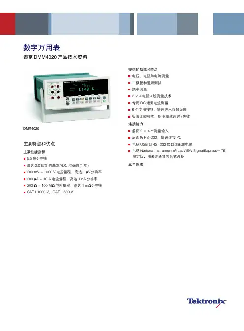
数字万用表
泰克 DMM4020 产品技术资料
DMM4020
主要特点和优点
主要性能指标 5.5 位分辨率 高达 0.015% 的基本 VDC 准确度(1 年) 200 mV - 1000 V 电压量程,高达 1 µV 分辨率 200 µA - 10 A 电流量程,高达 1 nA 分辨率 200 Ω - 100 MΩ 电阻量程,高达 1 mΩ 分辨率 CAT I 1000 V,CAT II 600 V
双显示器 通过独有的双显示器,您可以从一组测试表笔,测量同一信号 的两个不同参数。
极限比较是接近极限的测试结果。
简单准确的 4 线测量 2×4欧姆功能已获专利的分离端子插座允许只使用两条引线、 而不是四条引线,执行 4 线测量。泰克提供了专用测试线附件, 可以建立连接。您可以获得杰出的分辨率和准确度,而且使用 一对引线非常方便。
*3 不确定度计算公式为±(% 的读数 + % 的量程)。
90 天 23℃± 5℃ 0.8 + 0.05 0.15 + 0.05 0.3 + 0.05 0.8 + 0.05 0.8 + 0.05 0.15 + 0.05 0.3 + 0.05 0.8 + 0.05 0.8 + 0.05 0.15 + 0.05 0.3 + 0.05 0.8 + 0.05 0.8 + 0.05 0.15 + 0.05 0.3 + 0.05 0.8 + 0.05 0.8 + 0.05 0.15 + 0.05 0.3 + 0.05 0.8 + 0.05
基于HT5017芯片的SoC单相智能电表
基于HT5017芯片的SoC单相智能电表徐京生【摘要】采用SoC方案设计了一款高准确度、低成本、低功耗的单相智能电能表。
该电能表采用SoC芯片HT5017作为控制核心。
HT5017是一颗低功耗、高性能的单相电能计量SoC芯片,片内集成了32-bit ARM内核、128 K lfash和8 K SRAM,其支持断相防窃电功能的硬件EMU模块,带有温度自补偿功能的高准确度RTC模块以及LCD驱动器。
该设计为单相多功能、防窃电电能表提供了高集成的单芯片解决方案。
小批生产结果表明,所设计的电表完全满足海外客户的技术要求,具有广泛的市场推广价值。
%A high-precision, low-cost, low-power single-phase smart electric energy meter is designed by adopting SoC chip HT5017 as a control core. HT5017 is a low-power, high-performancesingle-phase energy metering SoC chip, in which 32-bit ARM core, 128 K lfash and 8K SRAM are integrated, which supports hardware EMU module with open-phase anti-tamper features and high-precision RTC modulewith temperature compensation functions, as well as LCD drivers. The design provides a highly integrated single-chip solution for single-phase, multi-functional, anti-tampering electric energy meter. Results of small batch production show that the single-phase smart electric energy meter could completely meet the technical requirements of overseas customers with a wide range of marketing value.【期刊名称】《上海计量测试》【年(卷),期】2016(043)006【总页数】5页(P32-36)【关键词】SoC;电能计量;单相智能电能表;HT5017【作者】徐京生【作者单位】华立科技股份有限公司【正文语种】中文当前,通用的分立设计方案电能表一般采用微控制器单元(Micro Control Unit,MCU)加专用计量芯片、时钟芯片和液晶驱动芯片等外围器件的独立芯片完成独立的计量、时钟、液晶显示(liquid crystal display,LCD)和数据管理功能[1]。
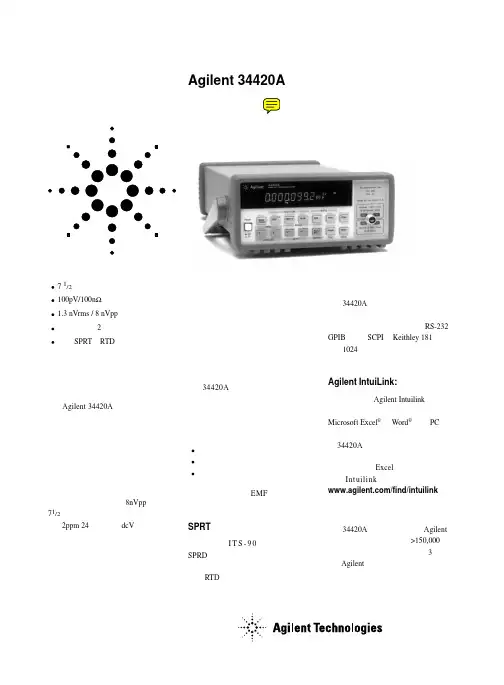
安捷伦数字万用表34420A技术资料
低功率电阻 5
1.0000000Ω 10.000000Ω 100.00000Ω 1.0000000kΩ 10.000000kΩ 100.00000kΩ 1.0000000MΩ
10mA 10mA 1mA 100µA 10µA 5µA 5µA
0.0015+.0002 0.0015+.0002 0.0015+.0002 0.0015+.0002 0.0015+.0004 0.0015+.0012 0.0伏级的性能
Agilent 34420A 纳伏 / 微欧表是适 用于进行低电平测量的高灵敏多用表。 它把低噪声电压测量与电阻和温度功能 结合在一起,建立了灵活的低电平测量 和高性能的新标准。
去掉低电平测量的不确定性
34420A 把低噪声纳伏输入与高稳 定度电流源相组合,以提供精密的低电 平电阻测量 ── 从而避免了外电流源 的成本和复杂性。所包括的三种电阻模 式为:
LO 引线电阻,10Ω 量程限制为 10.5Ω,100Ω 量程限制为 105Ω。 7 对于 25Ω SPRT,在最后 4 小时内用水的三相点检查。未经水三相点检查时,24 小时
指标增加 0.0130C,90 天指标增加 0.0350C,1 年指标增加 0.550C。 8 对于固定的参考结,外参考结增加 0.30C,内参考结增加 2.00C。 9 在 2 小时预热后,6.5 位(10 PLC),模拟滤波器关,数字滤波器为中(50 读数平均)。
系统速度 6
配置速率:
26/s 至 50/s
自动速率(电压):
> 30/s
ASCII 读数至 RS-232: 55/s
ASCII 读数至 GPIB: 250/s
最大内触发速率:
SN75107BD 数据手册说明书
SN75107AJ SN75107BJ SN75108AJ SN75108BD SN75108BJ SN75108BN SN75109AJ
SN75109J
SN75109N
SN7510FA SN7510FA SN7510FA SN7510FA SN7510L SN7510L SN7510L SN7510P SN7510P SN7510P SN7511FA
N/A
IC Datasheets -
/SN7510L-datasheet.html
Shortform
Texas Instruments
Differential Video Amplifier
/SN7510L-datasheet.html
Advanced Micro Devices
Differential DriverTransmitter - ConstantCurrent Output
/SN75109N-datasheet.html
Texas Instruments
General Purpose Video Amplifier
Shortform
Texas Instruments
Differential Video Amplifier
/SN7510P-datasheet.html
Texas Instruments
General Purpose Video Amplifier
Differential Video Amplifier
/SN7510FA-datasheet.html
Texas Instruments
General Purpose Video Amplifier
七位半数字多用表技术参数
七位半数字多用表技术参数一、引言七位半数字多用表是一种电子测试仪器,用于测量电流、电压、电阻、频率等电学参数。
本文将详细介绍七位半数字多用表的技术参数,并对其重要性进行分析。
二、精确度七位半数字多用表的精确度是衡量其测量能力的重要指标。
通常用百分比或最大允许误差来表示。
例如,一款七位半数字多用表的精确度为0.01%,意味着在测量中,其最大允许误差为测量值的1/10000。
精确度越高,测量结果越可靠。
三、测量范围七位半数字多用表的测量范围是指它可以准确测量的最小和最大值。
例如,一款七位半数字多用表的电压测量范围为0-1000V,电流测量范围为0-10A。
测量范围的选择要根据具体的应用需求来确定,选择适合的测量范围可以提高测量的准确度和精度。
四、分辨率七位半数字多用表的分辨率是指它可以显示的最小单位。
一般以位为单位进行表示。
例如,一款七位半数字多用表的分辨率为0.1mV,意味着它可以显示到0.1mV的小数位。
分辨率越高,可以显示的细节越丰富,对于测量小信号时更加有优势。
五、采样速率七位半数字多用表的采样速率是指它对输入信号进行采样的速度。
采样速率越高,可以更快地捕捉到信号的变化,对于测量高频信号或快速变化的信号非常重要。
例如,一款七位半数字多用表的采样速率为1MS/s,意味着它每秒可以进行100万次采样。
六、阻抗七位半数字多用表的阻抗是指在测量电阻时,它对被测电路的影响程度。
一般以欧姆为单位进行表示。
例如,一款七位半数字多用表的输入阻抗为10MΩ,意味着在测量电阻时,它对被测电路的影响极小,可以有效保证测量结果的准确性。
七、界面和通信七位半数字多用表通常具有多种界面和通信功能,以便用户与其进行交互和数据传输。
常见的界面包括USB、RS232、LAN等,可以通过这些界面将测量数据传输到计算机或其他设备上进行分析和处理。
同时,也可以通过这些界面进行仪器的控制和设置。
八、附加功能七位半数字多用表还常常具有一些附加功能,以满足不同应用场景的需求。
72-7780真RMS数字多功能电阻计用户指南说明书
True RMS Digital Multimeter Model: 72‐7780User ManualI. Overview72‐2800 is a professional handheld true RMS multimeter with wide scope of application. It is a safe, stable and reliable measurement device for AC/DC, resistance, diode, continuity, capacitance, frequency, NCV measurement etc.II. Unpacking InspectionOpen the package box and take out the device. Please check whether the following items are deficient or damaged and contact your supplier immediately if they are. •User manual‐‐‐‐‐‐‐‐‐‐‐‐‐‐‐‐‐‐‐‐‐‐‐‐‐‐‐‐1pc•Test leads‐‐‐‐‐‐‐‐‐‐‐‐‐‐‐‐‐‐‐‐‐‐‐‐‐‐‐‐‐‐‐‐1pair•K‐type thermocouple‐‐‐‐‐‐‐‐‐‐‐‐‐‐‐‐1pc•Optional current clampIII. Safety informationSafety Standards•EN 61010‐1:2010•CAT III 600V, double insulation standard, over voltage standard, and RoHS, pollution grade IIPlease read and comply with the safety information carefully, or the protection provided by the device may be impaired.1.Do not use the device if the rear cover is not covered up or it will pose a shockhazard2.Do not use the device if the device or test leads appear damaged or if yoususpect that the device is not operating properly. Pay particular attention to the insulation layers.3.To avoid false reading, replace the battery when the battery indicatorappears.4.Functional dial should be switched to proper position.5.Never input voltage and current exceeding the value listed on the device.6.Do not switch the functional dial during measuring.7.After each measure, disconnect the test leads with the circuit. For measuringcurrent, switch off the power supply before test leads disconnection, especially important for measuring large current.e caution to measure voltage >DC 60V or AC 30Vrms.9.Do not use or store the device in high temperature, high humidity, flammable,explosive or strong magnetic field environments.10.Do not change the internal circuit of the device in order to avoid the damage tothe device and users.e damp cloth to clean the case; do not use detergent containing solvents orabradants.IV. SymbolsLow batteryBuzzer indicatorV.1)Max voltage between input terminals and earth grounding: See TechnicalSpecifications2)Fuse Type:10A Jack: F 10A H 600V Fuse (Φ6x25) mmmA/μA Jack: F 600mA H 600V Fuse (Φ6x32) mm3)Max Display Value:Capacitance measurement: 9999Frequency measurement: 9999Other measurement: 6000Duty Ratio:1~99.9%Diode: 3.2VOthers:1)Range: Auto/Manual2)Polarity: Auto3)Display updates 2~3 times for every second. Overrange Indicator: “OL”4)Operating temperature: 0˚C~40˚C (32˚F~104˚F)Storage temperature: ‐10 ˚C~50 ˚C (14 ˚F~122 ˚F)Relative humidity: ≤75% at 0 ˚C~30 ˚C; ≤50% at 30 ˚C~40 ˚C5)Operating altitude: 0~2000m6)Battery type: AA R6P 1.5V×27)Low power indicator:8)Dimension: 175mm×80mm×48.5mm9)Weight: 350g (batteries included)10)Electromagnetic compatibility:RF≤1V/m, overall accuracy=specified accuracy+5% of range.RF>1V/m, no specified calculation.VI. Structure (see figure 1)1/ Protective case2/Display screen3/4/7 Functional buttons5/Functional dial6/ Input jacksVII. Display━AutoΩHzVIII.V、V、Hz%˚C/mA 60ANCV Non‐contact voltageOFF shutdownButtons:RANGE:Switch the range mode to auto/manual and then cycle through all ranges. To exit auto/manual mode, press the button for 2 seconds or switch the functional dial. (Only for V,Ω,I measurement)MAX/MIN:Starts and stops Max/Min recording. To exit this mode, press the button for 2 seconds or switch the functional dial. (Only for V,Ω,I and ˚C /˚Fmeasurement)REL:Save the first reading as reference value. The second reading=second measurement value‐reference value. To exit his mode, press the button for 2 seconds. (Only for V,Ω,I and ˚C /˚F and measurement); when measuring capacitance,REL button is only used for eliminating intrinsic value.Hz/%:When measuring AC voltage/ current, press the button to cycle through frequency and duty ratio measurement.SELECT:Select functions. Under AC modes, long press the button until UFC appears to enter VFC measurement mode and measure the variable frequency voltage. Long press gain to exit VFC measurement mode.HOLD:Press the button once to hold the reading. Press again to unlock the reading and enter general measurement modes.IX. Operation instructionsTo avoid false reading, replace the battery if the battery low power symbolappears. Also pay special attention to the warning sign besides the test lead housing, indicating that the tested voltage or current must not exceed the valueslisted on the device.1. AC/DC voltage measurement (see Figure 3)1)Connect test leads with the load in parallel.2)When input impedance about 10MΩ, there ismeasurement errors. Input impedance≤10 kΩ,measurement errors can be ignored (≤0.1%)Notes:•Do not measure voltage over 600Vrms, or it may exposeusers to electric shock and damage the device.•Please pay extra attention when measuring high voltage inorder to avoid electric shock.2. Resistance measurement (see figure 4a)test leads with the resistance in parallel.•If the resistor is open or over the range, the “OL” symbolwill be displayed on the screen.•Before measuring resistance, switch off the power supplyof the circuit, and fully discharge all capacitors.•When measuring low resistance, the test leads will produce0.1Ω~0.2Ω measurement error. To obtain accuratemeasurement, short the test leads and use REL function.•If the resistance when shorted is more than 0.5Ω, please check if test leads are loosened or damaged.•When measuring high resistance above 60MΩ, it is normal to take a few seconds to steady the readings.•Resistance measurement can be used to inspect device’s internal fuses.( see figure 4b)•Do not input voltage over DC 60V or AC30V.3. Continuity measurement (see figure 5)If the resistance being measured is over 150Ω, circuit is in openstatus, buzzer does not go off. If the resistance less than 10Ω,circuit is in good conduction status, buzzer will continuously go off.Note:•To avoid damage to the device, before measuring continuity,switch off all power supplies and fully discharge all capacitors.•Do not input voltage over DC 60V or AC30V.4. Diode measurement (see figure 6)“OL” symbol appears when the diode is open or polarity isreversed.For silicon PN junction, normal value: 500 ~ 800mV (0.5 ~ 0.8V).Notes:•Switch off the power supply to the circuit, and fully dischargeall capacitors•Voltage for testing diode is about 3.1 V.•Do not input voltage over DC 60V or AC30V.5. Capacitance measurement (see figure 7)When there is no input, the device displays a fixed value(intrinsic capacitance). For small capacitancemeasurement, to ensure measurement accuracy, themeasured value must be subtracted from intrinsiccapacitance. Or users can measure small capacitycapacitors with relative measurement function (REL) (thedevice will automatically subtract the intrinsic•If the tested capacitor is shorted or its capacity is over the specified range “OL” symbol will bedisplayed on the screen.•When measuring large capacitors, it may take a few seconds to obtain steady readings.•Before measuring capacitors (especially for high voltage capacitors), please fully discharge them.6. Frequency/Duty ratio measurement (see figure 8) At the frequency position, press the Hz/% to select frequency/duty ratio measurement mode.Notes:•Do not input voltage over DC 60V or AC30V.7. Temperature measurement (see figure 9)Turn on the device, after “OL” symbol appears, insert K‐thermocouple into the device.Note:Only K‐type thermocouple is applicable. The measured temperature should be less than 230˚C/ 446˚F(˚F=˚C*1.8+32)8. AC/DC current measurement (see figure 10) Connect test leads with the tested circuit in series. Readings under this AC measurement is true RMS.•Before measuring, switch off the power supply of the circuit.•If the range of the measured current is unknown, select the maximum range and then accordinglyreduce.•There are fuses inside 10A jack and mA/μA jack. Do not connect the test leads with any circuits inparallel.•If the tested current is over 5A, each measurement time should be less than 10 seconds and the nexttest should be after 15 minutes.•When measuring AC current, press Hz/% button to display AC frequency or duty ratio.•60A AC and DC current clamp measurement (see figure 11)Connect as shown with the attached current clamp.9. NCV measurement (see figure 12)1)Switch the dial to NCV position2) Place the device near the measured object.“‐“ symbol indicates the intensity of the electricfield. More “‐“ and the higher the buzzer frequency,the higher the electric field intensity.3) Intensity of electric field* "EF": 0 ~ 50mV* "‐": 50 ~ 100mV* "‐‐": 100 ~ 150mV* "‐‐‐": 150 ~ 200mV* "‐‐‐‐":> 200mV .Notes:Test leads are not required for NCV measurement.10. Others• The device enters measurement status in 2 seconds after startup. Restart thedevice,”ErrE” appears.• The device automatically shuts down if there is no operation for 15 minutes.You can wake up the device by pressing any key. To disable auto shutdown,switch the dial to OFF position, long press SELETE button and turn on the device.symbol will disappear with one long beep. Recover the auto ‐off function byrestarting the device.• Buzzer notification1) Input voltage ≥ 600V (AC /DC), buzzer will continuously beep indicating measurerange is at limit2) Input current > 10A (AC/DC), buzzer will continuously beep indicating measurerange is at limit• Low power warnings: Voltage of the battery < 2.4V, symbol appears, thedevice can still be used. If voltage is lower than2.2V, the device cannot work andthe symbol disappears after startup.• The screen backlight cannot work if battery voltage less than 2.6V.X. Technical specificationAccuracy: ± (% of reading + numerical value in least significant digit slot), 1 YearWarrantyAmbient temperature: 23˚C±5˚C (73.4˚F±9˚F)Ambient humidity: ≤75% RH1. DC voltageRange Resoluti onAccuracy 60.00mV* 0.01mV ±(0.5%+2) 600.0mV** 0.1mV6.000V 0.001V±(0.7%+3) 60.00V 0.01V 600.0V 0.1V600V 1VInput impedance: about 10M Ω.Results might be unstable at mV range when no load is connected. The valuebecomes stable once the load is connected. Least significant digit ≤±3Max input voltage: ±600V, when the voltage ≥ 600V, "OL” symbol appears and thebuzzer goes off.”2.AC voltageRange Resolution Accuracy60.00mV 0.01mV ±(1.0%+3) 600.0mV 0.1mV6.000V 0.001V±(0.8%+3) 60.00V 0.01V600.0V 0.1V600V 1V ±(1.0%+3)VFC 200.0V~600V 0.1/1V ±(4.0%+3)Input impedance: about 10M ΩDisplay true RMS. Frequency response: 45Hz ~1KHz (LPF 45~400Hz)Accuracy guarantee range: 5 ‐100% of the range, shorted circuit allows leastsignificant digit ≤10 Crest factor at Max range=3.0 (excluding 600Vrange, crest factor=1.5)Max input voltage: 600Vrmstest leadsOpen circuit voltage=1V (Current=0.4mA)Overload protection:600V ‐PTCTest capacitance≤100nF, adapt REL mode.Input range: (DC level=0)≤100kHz: 100mVrms≤a≤20Vrms> 100 kHz~1MHz: 200mVrms≤a≤20Vrms>1MHz: 500mVrms≤a≤20Vrms>5MHz~10MHz: 1Vrms≤ a ≤20VrmsDuty ratio%:Only for frequency measurement≤100kHzNotes:When measuring AC voltage or current, following conditions should be satisfied:Frequency response≤1kHzAC voltage: mV position≥100mV; V position≥Range×6%AC current: input range: 4000/6000μA, 400/600mA, 10A: A≥range×6%400/600μA, 40/60mA, 4/6A:A≥range×60%•K‐type thermocouple is only applicable for temperature less than 250˚C/482˚F.μA mA range: F1Fuse (φ6×32)mm FF 600mA H 600V10 A range:F2Fuse (φ6×25)mm FF 10A H 600V 9. AC currentRange Resolution AccuracyμA600.0μA 0.1μA±(1.0+3) 6000μA 1μA mA 60.00mA 10μA 600.0mA 0.1mAA 6.000A 1mA ±(1.2%+3) 10.00A 10mAFrequency response: 45~1kHzDisplay: true RMSAccuracy guarantee range: 5 ‐100% of the range, shorted circuit allows least significant digit ≤2Crest factor at Max range=3.0Overload protection: (similar to DC current)XI. MaintenanceWarning: Before opening the rear cover, switch off the power supply (remove test leads from the input terminal and the circuit).1. General maintenance1) Clean the case with a damp cloth and detergent. Do not use abradants or solvents2) If there is any malfunction, stop using the device and send it to maintenance.3) The maintenance and service must be implemented by qualified professionals ordesignated departments.2. Replacements (see Figure13)Battery replacement:To avoid false reading, replace the battery when thebattery indicator appears.Battery Specification: AA 1.5Vx21) Switch the dial to “OFF “position and remove thetest leads from the input terminal.2) Take off the protective case. Loosen the screw onbattery cover; remove the cover to replace thebattery. Please identify the positive and negativepole.Fuse replacement:1) Switch the dial to “OFF “position and remove the teat leads from the input terminal2) Loosen the both screws on the rear cover, and then remove the rear cover to replace the fuseFuse specificationF1 Fuse φ6×32mm FF 600mA H 600VF2 Fuse φ6×25mm FF 10A H 600VTenma Test Equipment405 S. Pioneer Blvd.Springboro, Oh。
PF9800 系列用户手册说明书
- 1、下载文档前请自行甄别文档内容的完整性,平台不提供额外的编辑、内容补充、找答案等附加服务。
- 2、"仅部分预览"的文档,不可在线预览部分如存在完整性等问题,可反馈申请退款(可完整预览的文档不适用该条件!)。
- 3、如文档侵犯您的权益,请联系客服反馈,我们会尽快为您处理(人工客服工作时间:9:00-18:30)。
高精度七位半数字万用表 PREMA 5017
厂家: 德国普瑞玛
尺寸: 94×225×375mm
重量: 约3.4kg
一、特点
∙七位半数并且多种功能:VDC,VAC,IDC,IAC,Ω,℃,Hz…
∙带有RTD传感器的温度测量(Pt10,Pt100,Pt500,Pt1000)
∙根据用户需要,可提供20通道高速扫描器,可做资料采集
∙使用专利多斜A/D积分法,确保结果的精度及线性度
∙通过带有PREMA特殊指令的IEEE488和RS232接口控制
∙高分辨率:10nV,100pA,10μΩ以及0.001℃
∙稳定度:4ppm/24小时
∙精度:20ppm/1年
二、技术指标
1、直流电压
8、接口
IEEE488和RS232 接口
9、扫描仪
10、通用指标
机壳: 抗电磁干扰的铝制机壳
预热时间: 对满1年精度达2小时
11、附件
6000/03 用于扫描仪输入的Sub/D连接器5021G 用于5017(2HU)的19”支架安装工具5023K IEEE488接口电缆,2米
5024/25 用于PC机的IEEE488接口卡
3110 用于扫描仪输入的转换卡(1极40通道) 3011 Pt100表面探头1/3DIN
3012 Pt100浸入式探头(-50℃—+600℃) 3014 安全测试线
3015 精密测试线
3016 3种短路的设置(镀金) 3017 10安培分流器(0.1%DC精度)。