2016-04 Optimal spacing of sequential and simultaneous fracturing in horizontal well
水力压裂设计的新模型和新方法
水力压裂设计的新模型和新方法翁定为1,2 付海峰1,2 梁宏波1,21.中国石油勘探开发研究院廊坊分院压裂酸化中心2.国家能源致密油气研发中心储层改造部翁定为等. 水力压裂设计的新模型和新方法.天然气工业,2016,36(3):49-54.摘 要 压裂设计是水力压裂技术的核心,由于非常规储层的特殊性,使得压裂设计面临一系列的挑战。
为此,梳理了国内外压裂设计各环节的新模型和新方法,并分析了其发展方向。
压裂设计的新模型和方法主要分布在储层描述、水力裂缝刻画、水力裂缝优化以及水力裂缝模拟等4个方面,其中储层描述主要是在创新参数获取基础上建立新的地质力学模型;水力裂缝刻画主要体现在开发新方法,并结合物理模拟实验认识,提高现有监测手段的准确性;水力裂缝优化方面主要进展是挖掘储层与流体的相互作用,并通过规律性描述,形成新型的油气藏数值模拟软件;水力裂缝模拟主要通过方法创新,研发新型的适用于水平井分段多簇压裂的裂缝数值模拟器。
因此,建议国内同行在坚持工具、设备等硬件投入的基础上,加强基础研究,力争在各种评价模型和软件方面取得突破,从而提高压裂设计的科学性,进而实现非常规油气藏的高效经济开发。
关键词 水力压裂压裂设计储层描述裂缝刻画水力裂缝优化裂缝模拟数学模型国内外DOI:10.3787/j.issn.1000-0976.2016.03.007New models and methods for hydraulic fracturing designWeng Dingwei1,2, Fu Haifeng1,2, Liang Hongbo1,2(1. Fracturing and Acidizing Center, Langfang Branch of PetroChina Research Institute of Petroleum Exploration and Development, Langfang, Hebei 065007, China; 2. Stimulation Department of National Energy Tight Oil and Gas R&D Center, Beijing 100083, China)NATUR. GAS IND. VOLUME 36, ISSUE 3, pp.49-54, 3/25/2016. (ISSN 1000-0976; In Chinese)Abstract: Fracturing design is the core of hydraulic fracturing technologies. The particularity of unconventional reservoirs brings about challenges to the fracturing design. In this paper, the development direction of fracturing design was analyzed after new models and methods for fracturing design all over the world were investigated. These new models and methods mainly involve reservoir description, and fracture depiction, optimization and simulation. Reservoir description mainly involves a new geomechanical model built based on the acquisition of innovation parameters. Fracture depiction focuses on new method development to increase the accuracy of the existing monitoring means based on physical simulation experimental results. Progress in fracture optimization focuses on the interaction between reservoirs and fluids and the development of new numerical reservoir simulation models on the basis of law description. Hydraulic frac-ture stimulation involves the research and development of new numerical fracture simulators suitable for multi-stages and multi-clusters fracturing in horizontal wells by means of innovative methods. It is strongly recommended to strengthen basic research and try to realize breakthroughs in terms of various evaluation models and software so as to improve the quality of fracturing design and develop uncon-ventional resources efficiently and economically in China while the investment on tools and equipments are guaranteed.Keywords: Hydraulic fracturing; Fracturing design; Reservoir description; Fracture depiction; Hydraulic fracture optimization; Fracture simulation; Mathematical model; Domestic and overseas基金项目:国家科技重大专项“低渗、特低渗油气储层高效改造关键技术”(编号:2011ZX05013-003)。
高德利老师-现代油气井工程理论和方法概论2016
现代油气井工程理论和方法概论
高德利
2016年11月01日,北京
提 纲
一.油气井工程学科概念 油气井工程学科概念 二 现代油气井基本特征 二.现代油气井基本特征 三 油气井工程技术关键 三.油气井工程技术关键 四.特殊工艺钻完井技术 五.复杂井工程特点与挑战 复杂 程特 六.结束语
钻完井化学 与安全环保
一、油气井工程学科概念 、油气井工程学科概念
•油气井工程学科工学硕士学位获得者,应在油气井 钻井、完井、测量及防护等方面具有坚实的理论基础, 掌握较多的专业知识 了解本学科发展动态 能够运 掌握较多的专业知识,了解本学科发展动态,能够运 用数理方法、化学方法、计算机技术及现场资料等, 分析和解决油气井工程设计和作业问题;应掌握一门 外语 能够熟练阅读和撰写论文 并具有 定的听 外语,能够熟练阅读和撰写论文,并具有一定的听、 说能力;应具备一定的独立开展科研工作的能力,在 某一研究方向上有较深入的研究,并有所创新;还应 具备良好的科学作风。 具备良好的科学作风
一、油气井工程学科概念
目前全世界广泛采用钻井方式,是水力辅 助机械破岩的旋转钻井方式:
① 转盘(或顶驱)驱动旋转钻井方式:由钻头、钻铤及 稳定器等组成的BHA;带旋转导向工具的BHA; ② 井下动力钻具:螺杆钻具、涡轮钻具等; ③ 复合钻井方式(双驱):井下动力钻具+钻柱旋转; ④ 旋转导向钻井:推靠式、指向式等; ⑤ 冲旋钻井方式:液动冲击器、空气锤等; ⑥ 带扭力冲击器的旋转钻井; 带扭力冲击器的旋转钻井 ⑦ 特殊工艺钻井:欠平衡/气体钻井、套管钻井、连续管 钻井、膨胀管钻井、反循环钻井,等。
US4085803 US4344485 US4577651
页岩油储层压裂–提采一体化研究进展与面临的挑战

◄油气开发►doi:10.11911/syztjs.2024012引用格式:张衍君,王鲁瑀,刘娅菲,等. 页岩油储层压裂–提采一体化研究进展与面临的挑战[J]. 石油钻探技术,2024, 52(1):84-95.ZHANG Yanjun, WANG Luyu, LIU Yafei, et al. Advances and challenges of integration of fracturing and enhanced oil recovery in shale oil reservoirs [J]. Petroleum Drilling Techniques ,2024, 52(1):84-95.页岩油储层压裂–提采一体化研究进展与面临的挑战张衍君1, 王鲁瑀2, 刘娅菲1, 张佳亮3, 周德胜1, 葛洪魁3(1. 西安石油大学石油工程学院, 陕西西安 710065;2. 香港理工大学土木及环境工程系, 香港 999077;3. 中国石油大学(北京)非常规油气科学技术研究院, 北京 102249)摘 要: 页岩油储层压裂开发中,以远超地层吸收能力的注入速率向储层注入包含各类添加剂的工作液,基本完成了压裂介质一次注入、油井开发全生命周期受益的使命。
其中,2个问题尤为关键:1)如何形成均匀展布的裂缝网络,增大裂缝和储层的接触面积、提高液体流动效率?2)在形成高效传压传质缝网的基础上,存地压裂液如何提高储层中原油的可动性?压裂和提采一体化是解决上述问题的重要思路。
为此,阐述了页岩油储层压裂–提采一体化的内涵,归纳了实现压裂–提采一体化的模拟和试验技术;明确了页岩油储层压裂–提采一体化的科学问题:均衡应力压裂形成均匀展布的缝网,提高均布缝网中流体流动与传输的效率,强化基质孔隙中油气的动用。
同时,指出了压裂–提采一体化面临的挑战:明确裂缝非均匀扩展导致的压裂井间干扰机理并建立控制方法,形成裂缝中高压流体高效作用于基质孔隙的途径,揭示压裂液–储层–原油相互作用提高原油可动性机理。
Frac Point 贝克休斯
14
Drill Out of Seats 钻掉球座
Full Opening after Drill Out 钻掉后全通径 Test Time = 20 mins 测试时间=20分钟
11
Ball Activated Frac Sleeve 投球驱动压裂滑套
z
z
z
z z z 12
Design based on field proven CMU Sliding Sleeve 基于被油田证明的CMU滑套的设计 Exit ports designed with twice the flow area as tbg 设计出口流量是油管流量的两倍 HP/HT Dura-Frac Balls designed with low SG Dura-Frac 压裂球比重低且耐高压/高温 Over 10,000 runs from 1992 to 2006 自92至06年使用超过10000个 Transitional Ball Seat Geometry eliminates erosion 球座几何形状降低了冲蚀 Cast Iron Seats insure easy drill out 铸铁球座便于钻掉
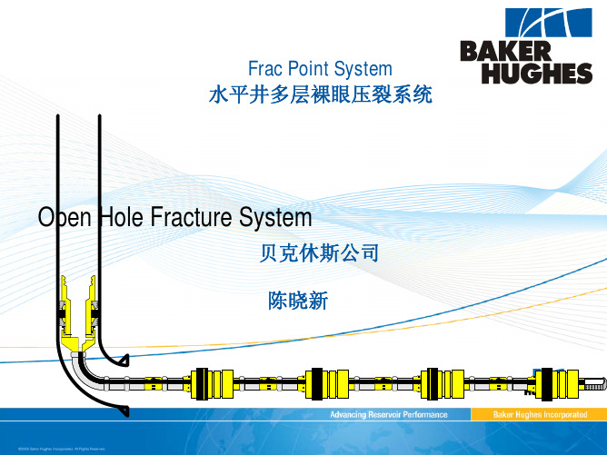
Frac Point System 水平井多层裸眼压裂系统
Open Hole Fracture System
贝克休斯公司 陈晓新
Agenda 议程
Primary Objectives 主要作业目的 System and Component Overview
系统及部件介绍 Frac Point System Animation 作业过程展示
人工压裂水平井研究综述

大庆石油学院学报第26卷 第4期 2002年12月J OURNAL OF DAQING PETROLEUM INSTITUTE Vol .26 No .4 Dec . 2002收稿日期:2002-05-31;审稿人:卢祥国 作者简介:刘振宇(1964-),男,博士生,副教授,主要从事油藏描述、试井分析方面的研究.人工压裂水平井研究综述刘振宇1,刘 洋2,贺丽艳3,翟云芳1(1.大庆石油学院石油工程学院,黑龙江大庆 163318; 2.大庆石油学院土木建筑工程学院,黑龙江大庆 163318; 3大庆油田有限责任公司第一采油厂,黑龙江大庆,163001) 摘 要:综述了水平井压裂技术在国内外的研究状况,重点讨论了压裂水平井的渗流规律、裂缝的优化以及与压裂垂直井的产能比较.结果表明:压裂水平井的开发效果和经济效益均优于压裂垂直井,其中,横向裂缝水平井的生产效果好于纵向裂缝水平井,当沿地层裂缝方向的渗透率与沿井筒方向的渗透率之比小于或等于1时,横向裂缝的最佳产能条数为3~5条.关 键 词:人工压裂;水平井;渗流;横向裂缝;产能中图分类号:TE357.14 文献标识码:A 文章编号:1000-1891(2002)04-0096-040 引言水平井是开发油气田的一种有效手段,应用水平井可开发一般性的油气藏以及特殊性油气藏,包括低渗透油藏、低渗透气藏、底水油藏、稠油油藏等.据统计,至1995年底,全世界的水平井总数为14600多口[1],其中很多是打在低渗透油气藏.至1997年底,我国共钻水平井159口[2],其中有20口井钻在低渗透油藏,它们分布在大庆、胜利、新疆、辽河、华北、中原、四川等油区.文中对水平井压裂用于开发低渗透油气田的问题做了广泛的调研,对其中一些重要的问题进行了综述,可为该项技术的实际应用和进一步研究提供一定的参考.1 水平井人工裂缝的形态第一个论及水平井压裂问题的是1985年的Giger [3],他在“非均质油藏中水平井的开采技术”一文中指出,水平井是开发非均质性油藏的一种好方法,因此,只要固井技术一旦达到工业化应用,水平井压裂的设想就会实施.可见他是以预见性的观点指出了该技术的发展潜力.1987年,Giger [4]首次提出了利用水平井开发低渗透油田,给出了水平井与垂直井相比的当量半径,用以作为打水平井的经济界限.1992年,Br own [5]指出压裂效果最好的是北海Danish 油田,该油田地层的渗透率为1.0×10⁻³μm 2,共打了10口水平井,每口水平井开始压裂5条裂缝,后来最多压到10条,实践证明压裂是十分有效的.但同时指出,并非所有的水平井压裂都有效.水平井人工裂缝一般有3种形态:横向缝、纵向缝、水平缝.横向缝是指裂缝面与水平井井筒相垂直图1 水平井裂缝形态示意图的裂缝,一般可以产生多条横向缝;纵向缝是指裂缝面沿水平井井筒方向延伸的裂缝;水平缝是指裂缝面沿水平方向延伸的裂缝.对于一口水平井,实际压裂后将产生哪一种形态的缝,要取决于地应力的情况.一般而言,最小地应力位于水平方向,因此在现场中遇到最多的是横向缝和纵向缝,其形态见图1.如果井筒平行于最小水平主应力方向(即沿最小水平渗透率方向),则产生横向缝;如果水平井筒垂直于最小水平主应力方向(即沿最大水平渗透率方向),则产生纵向缝.理论研究和实际应用表明,横向缝的生产效果好于纵向缝,因此,文中将重点讨论横向缝. 图2 压裂水平井与压裂垂直井的采油指数比随裂缝延伸程度的变化2 压裂水平井的产能分析1985年,Giger [3]在理论上计算并比较了压裂水平井与压裂垂直井的采油指数比随裂缝延伸程度的变化规律,结果见图2.纵坐标为压裂水平井与压裂垂直井的采油指数比,横坐标为压裂水平井的裂缝长度与水平井井筒的长度之比,不同曲线对应不同的裂缝条数.计算条件为:裂缝为无限导流,边界为正方形且不渗透,地层长度为400m ,厚度为170m .由图2可知,当水平井的裂缝为4条以上时,水平井的产能将随裂缝长度的增加而提高,否则效果将不佳.1988年,Mercer [6]提出用水平井作为加密井开发致密的裂缝地层,并且是作为一种开发战略而提出的.对气藏的研究结果表明,4口未压裂的水平井的产气量相当于16口垂直井产气量的1.5倍,2口压裂水平井的产气量与4口未压裂水平井的相当,说明水平井压裂后的效果最好.图3 直井与水平井产量对比 1996年,Elrafie [7]以某油田为例比较了直井-垂直裂缝直井-横向裂缝水平井的产油量,结果见图3.由图3可知,横向裂缝水平井的生产效果明显优于其它2种情况.表明对水平井压裂是一项经济有效的生产措施.1992年,Brown [5]系统地分析了垂直裂缝直井与未压裂水平井的动态状况,对比了在不同渗透率的各向同性地层以及各向异性地层中具有相同生产指数和一定缝长的垂直裂缝直井所对应的水平井长度,结果表明,油层的渗透率越低,所需水平井的井筒越长;同时指出,水平井压裂可以提高水平井的生产动态性能,其产能是未压裂水平井的3倍,但压裂水平井的费用却是未压裂水平井的1.4倍,因而压裂水平井具有良好的经济效益.特别指出,横向裂缝水平井比纵向裂缝水平井效果更好.3 压裂水平井的渗流特点及裂缝条数优化图4 横向裂缝水平井的流态 1995年,Horne [8]研究了水平井中多条横向人工裂缝的瞬态压力特性,其流态见图4.由图4可知,可将水平井中多裂缝的流动形态分为4部分:(1)第一线性流,指地层向各条裂缝和裂缝向井筒的线性流动.(2)第一径向流,指若缝较短且间距较大,则在各裂缝周围产生的拟径向流,需要指出的是,若裂缝不是很短和间距不是很大,则不能产生这样的拟径向流.(3)第二线性流,指在流动后期,若边缘很远且缝很短很密,则产生流线相互平行,且垂直于水平井轴线的线性流动,(4)第二径向流,指对于整个油藏,如果生产时间很长,则流体以径向流的形式向水平井及裂缝区域的流动.以上所述的流态特点在压力及压力导数理论曲线上有所表现,特别是压力导数曲线的特征尤为明显.图5为2条裂缝情况下水平井井筒长度为裂缝半长10倍时的压力及压力导数理论曲线.由图5可知,第一线性流的双对数压力线及导数线均为斜率为1 2的直线,第一径向流的导数线为p ′D 值为14的水平线,第二径向流的导数线为p ′D 值为12的水平线,第二线性流在这里未表现出来.对于4条裂缝情况,其理论第4期 刘振宇等:人工压裂水平井研究综述图5 2条裂缝的压力及压力导数理论曲线曲线与图5相似,只是第一径向流的导数线为1 8水平线,第二径向流导数线仍为1 2水平线.如果存在井筒储存效应,当井储较大时,前3个流动时期可能被淹没,只有第二径向流特征比较分明.研究表明,在生产一定时间后,水平井中的多条裂缝之间将产生干扰,以至于影响各裂缝的产能.Elrafie [7]模拟研究的8条横向裂缝,沿井筒延伸方向等距分布,各裂缝的性能完全相同.裂缝编号为1~8,其中第1和第8条缝位于最外侧,第2和第7条缝位于次外侧,第4和第5条缝位于最中心.各条裂缝的无因次产量的动态变化见图6,图中标出了各裂缝的编号.图6表明,在生产初期,各条裂缝的产量相同,但当生产时间较长时,每条缝的产量有所变化,越靠外侧的缝产量越高,图中的第1和第8条缝的产量比初期的产量高,其它缝的产量均比初期产量低,位于最中心的第4和第5条缝的产量最低.这表明,在生产一段时间后,裂缝之间的流动将产生干扰,愈靠近内部的缝所受到的干扰愈大,产量则愈低,这与文献[8,9]中给出的结果一致.进一步研究表明,两个外侧缝的间距对采油指数的影响比较大,因此,采用不等距裂缝间距,特别是加大外侧裂缝间距对提高压裂水平井的产能是有益的.对水平井实施人工压裂所产生的裂缝条数不仅影响水平井的产能,同时也影响经济效益.因此裂缝条数的优化是一个十分重要的问题.Soliman [10]研究认为,如果沿裂缝方向的渗透率(K x )与沿井筒方向的渗透率(K y )相等或比较小,那么裂缝的最佳条数为3~5条,如果沿裂缝方向的渗透率比沿井筒方向的渗透率大,那么裂缝的最佳条数将有所增加.这说明,在优化裂缝条数时要考虑方向渗透率的影响.图7比较了K x K y =0.1,1,10时裂缝条数对产量的影响,其中最上面的3条曲线表示生产时间为2a ,下面的3条曲线表示生产时间为0.5a .由图7可知,K x K y 小于或等于1时,裂缝的最佳条数为3~5条.郎兆新等[11]在均质地层中的研究结果[11,12]亦表明,最佳横向裂缝的条数为3~5条,与以上结果基本一致.图6 各裂缝的产量动态变化图7 裂缝条数对产气量的影响 值得指出的是,不等距分布的裂缝间距的优化问题,是值得深入研究的问题,但目前这方面的研究还很少.4 结论(1)水平井人工裂缝可分为横向缝、纵向缝、水平缝3种形态,其中横向缝的生产效果好于纵向缝,压裂水平井的开发效果和经济效益均优于压裂垂直井;(2)水平井中多条横向裂缝的渗流形态可分为:第一线性流、第一径向流、第二线性流、第二径向流.(3)如果沿裂缝方向的渗透率与沿井筒方向的渗透率之比K x K y 小于或等于1时,产能高的最佳裂缝条数应为3~5条.大 庆 石 油 学 院 学 报 第26卷 2002年第4期 刘振宇等:人工压裂水平井研究综述参考文献:[1] 李道品.低渗透砂岩油田开发[M].北京:石油工业出版社,1997.227.[2] Liu X E,Liu S Q,J iang Z X.Horiz ontal Well Technol ogy in the Oilfield of China[J].SPE50424,1998.[3] Giger F M.Horizontal Wells Production Techniques in Heterogeneous R es ervoirs[J].SPE13710,1985.[4] Giger F M.Lo w-Permeability Reservoirs Development Us ing Horizontal Wells[J].SPE16406,1987.[5] Brown J E,Economides M J.An Anal ysis of Hydraul ically Fractured Horizontal Wells[J].SPE24322,1992.[6] M ercer J C,Pratt III H R,Yost A B.Infill Drilling Us ing Horizontal Wells:A Field Development Strategy for Tight Fractured Formations[J].SPE17727,1988.[7] ElR afie E A,Wattenbarger prehensive Evaluation of Horizontal Wells with Trans verse Hydraul ic Fractures in a Layered Multi-phase R es ervoir[J].SPE35211,1996.[8] Horne R N.R elative Productivities and Press ure Trans ient Modeling of Horizontal Wells with M ultiple Fractures[J].SPE29891,1995.[9] de Carvalho R S,R os a A J.Transient Press ure Behavior for Horiz ontal Wells in Naturall y Fractured Reservoir[J].SPE18302,1988.[10] Soliman M Y,Hunt James L,EI Rabaa A M.Fracturing Aspects of Horizontal Wells[J].JPT,1990,42(8):966~973.[11] 郎兆新,张丽华,程林松.压裂水平井产能研究[J].石油大学学报(自然科学版),1994,18(2):43~46.[12] Larry K B.Fracturing and Sti mulation Overview[J].JPT,2000,52(5):24.下期论文摘要预报杏北油田构造特征与油水井套管损坏之间的关系刘 威,王玉祥,王兴刚,窦春梅分析了松辽盆地大庆长垣杏树岗油田北部地区构造特征和油水井套管损坏分布状况.结果表明,地层倾角大的地区在层间压差较大及浸水域形成后,油水井套管所承受的剪切力增大,易发生套损;在相同开发条件下油水井套损率与地层倾角呈线性关系;断层面进水局部产生滑移,断层的分布交杂区形成异常高压,导致断层附近发生套损.提出了注水井排与断层上升盘夹角的三角区、断层走向与注水井排近于平行的窄条带区、两条相交断层开口端被注水井封闭区是易产生套损的地区,给出了预防套管损坏的措施.Abstracts Journal of Daqing Petroleum Institute Vol.26 No.4 Dec.2002pr ogram.The Implement of this approach can pr ovide a foundation for the decision making in oil development.Key words:oil development;oil commingling;economic evaluation;modelAnalysis of the determination process of option price2002,26(4):85~87PE NG Min1,YANG Hong-bo1,ZH AO Yue-kang2(1.Ec onomy and Manaage ment Colle ge,Daqing P etroleum Institute,Daqing,Heilongjiang163318,China;2. Institute of Recove ry,Daqing Oil Field Corp.Ltd.,Daqing,Heilongjiang161000)A bstract:This paper introduces the option price that is the one derivative financial instruments,and taking Europe type option as an example,analyzes the factor that affects option price,and has framed the fluctuation range of option price.The relationships between the intrinsic value and time value and option price have been analized.Key words:option price;call option;put option;assetImplementation of large oil equipment investment evaluation system2002,26(4):88~91TANG guo-wei1,YANG Hui1,SHAO Qiang2,SI Xiang-yu1(pute r Science and Enginee ring College,Daqing Petroleum Institute,Daqing,H eilongjiang163318,China;2.Ec onomy and Management College,Daqing Petroleum Institute,Daqing,Heilongjiang163318,China)A bstract:The evaluation index system for the integrated evaluation of large equipment of oil extraction is set up,in which5top-level index and13second-level index are included and the weight set is decided by using Analytical Hier-archy Process(AHP).Then the equipment is evaluated by using fuzzy integrated evaluation method and integrated grade method in order to decide the equipment status and to support the equipment investment decision for enterprises. Key words:large equipment;integrated evaluation investment;fuzzy mathematicsPositive solutions to a singular nonlinear three-point boundary value problem2002,26(4):92~95KONG Ling-bin,XU Kui-sheng(Dept of M athe matic s,Daqing Petroleum Institute,Daqing,H eilongjiang163318,China)A bstract:The singular nonlinear three-point boundary value pr oblem to a sec ond order differential equation is studied. It is proved that the problem has at least two positive solutions by employing the fixed point theorem for the mapping in cones.Key words:singular nonlinear three-point boundar y value problem;fixed point theorem in cones.Overview of the reserch of hydraulically fractured horizontal wells2002,26(4):96~99LIU Zhen-yu1,LI U Yang12,HE Li-yan3,ZAI Yun-fang1(1.Petroleum Engine ering Colle ge,Daqing Petroleum Institute,Daqing,H eilongjiang163318,China;2.Civil Engine ering College,Daqing Petroleum Institute,Daqing,Heilongjiang163318,China;3.Oil Recove ry Plant No. 1,Daqing Oil Feild Corp.Ltd.,Daqing,H eilongjiang163001,China)A bstract:In this paper,the current research of hydraulically fractured horizontal wells in the development of low-per-meability r eservoir is overviewed.Some inter esting topics,the flow mechanism of the fractured horizontal wells,the optimum of fracturing,and the comparison capabilities between a fractured horizontal well and a vertical well with a vertical fracture,ar e discussed.The results show that the fractured horizontal wells are better than the vertical wells with vertical fractur es in the respect of development efficiency and economy.Especially,the horizontal well with trans-verse fracture is more preferable to that with longitudinal fracture.When the per meability along the direction of fractur e is equal to or less than that along the direction of well bore,the optimum fracture number is3~5.Key words:hydraulically fracturing;horizontal wells;flow through porous media;production capability。
页岩气压裂(哈里伯顿)

7400
1.85 76.11
7400
1.79 68.08
7500
2.03 74.28 2.21 81.81
7600
7500
7700
-6 0 0 -5 0 0 -4 0 0 -3 0 0 -2 0 0 -1 0 0 0 100 200 300 400 500
7600
Distance Along Fracture (ft)
页岩气
自生自储且具备传统空隙度储层 页岩气吸附在有机质上 高天然Gamma 射线 (80-140 units) 粘土含量一般低于20-30% 主要是石英和碳酸盐 细砂粒,小空隙,高TOC? 产气机理? 是否满足达西定律? 从油源岩扩散?
如何定义页岩气储层?
煤层气
~100 % 吸附
高 TOC
致密气
~100 % 游离
200 Antrim Shale 160 G a s C o n ten t (s cf/to n ) New Albany Shale Caney Shale 120
80
40
0 0 2 4 6 8 10 12 14 16 18 20
TOC (Wt. %)
Core Testing - XRD
Gas Content - TOC
Results Sidetrack was avoided Optimized wellbore placement doubled gas production
Connecting to the reservoir 综合 利用GEMTM 和 ShaleLOG Seamless integration of mineralogy 找到最佳的压裂点 fracture stimulation Optimize hydraulic
胜利油田致密油储层体积压裂技术及应用
2019年3月第24卷第2期中国石油勘探CHINA PETROLEUM EXPLORATION DOI. 10.3969/j.issn. 1672-7703.2019.02.012胜利油田致密油储层体积压裂技术及应用张全胜李明张子麟陈勇张潦源李爱山(中国石化胜利油田分公司石油工程技术研究院)摘 要:胜利油田致密油储量丰富,储层埋藏深、物性差、岩性复杂,常规压裂后产量低、递减快,开发效益差。
通过技术攻关和配套完善,形成了适合于致密油储层的组合缝网压裂等压裂新工艺,在提高改造体积的同时,大幅度提高裂缝导流能力,提高压后效果,并针对纵向多层系油藏特点,形成了水平井多级分段压裂和直斜井多级分段压裂 两类改造模式,研发了可以在线连续混配施工的速溶型低浓度瓜尔胶压裂液体系,以及可与地表水、热污水混配、可 回收再利用的乳液缔合型压裂液体系,有效解决了大规模连续施工压裂液的配置、水源等问题;同时完善了井工厂实施模式和裂缝监测技术。
应用该技术成功开发了 Y227、Y22, Y104等致密油区块,大幅度提高了单井产能、延长了 有效期,提高了区块开发效益,带动了一批难动用储量投入有效开发,大幅提高了胜利油田致密油藏经济有效动用程度。
关键词:致密油,分段压裂;体积压裂;组合缝网中图分类号:TE357.1 文献标识码:AApplication of volume fracturing technology in tight oil reservoirs ofShengli oilfieldZhang Quansheng, Li Ming, Zhang Zilin, Chen Yong, Zhang Liaoyuan, Li AishanAbstract: The Shengli oilfield is rich in tight oil reserves, but the reservoirs characterized by deep burial, poor physical properties and complex lithology, leading to unsatisfactory development performance like low yield and fast production decline after conventional fracturingstimulation. Through researches and optimizations, new fracturing techniques, such as commingled fracture network stimulation, weredeveloped for tight oil reservoirs. While increasing the stimulated reservoir volume (SRV), these techniques can greatly improve fracture conductivity and post-fracturing performance. For the reservoirs with multiple layers vertically, two types of treatments were established, i.e. multi-stage fracturing of horizontal wells and multi-stage fracturing of vertical/deviated wells. A fast-dissolving low-concentration guar fracturing system that can be continuously mixed on line and a recyclable emulsion-associating fracturing fluid system that can be mixed with surface water and hot sewage were developed, which can effectively ensure the fracturing fluid preparation and water source for large-scale continuous fracturing operations. Moreover, the well-plant operation mode and fracture monitoring technique were upgraded. The proposed technology has been successfully applied in tight oil blocks such as Y227, Y22 and Y104. By greatly improving the single-well productivity and lifecycle, it helps increase the development benefit. Accordingly, the utilization degree of the tight oil in Shengli oil field has been improved economically and effectively.Key words: tight oil, staged fracturing, volume fracturing, comingled fracture network域改造技术和理念的进步,体积压裂技术开始成为致密储层的主流改造技术。
威德福完井工具
设计的附属工具采用钢丝进行操作,避免复杂的作业需求。
应用范围:
Optimax系列安全阀设计用于生产井或注入井中的液体或气体环境,它是完井管柱的一个组成部分,通过液压控制管线进行控制,控制管线加压使安全阀保持在打开状态,压力释放后安全阀关闭。如果发生井喷,这种工具在人为控制下能可靠关闭,可有效地保护人员、财产和环境的安全。万一安全阀发生故障,可以用锁定打开工具和控制管线连通工具将安全阀改装成可下入一个插入式钢丝安全阀,减少生产的停顿。
——Model W(E)-5
The Optimax™Series Tubing Retrievable Surface Controlled Subsurface Safety Valve (TRSCSSV) is Weatherford’s entry into the Safety Valve market. Utilising the latest technology and design philosophy, this product is designed to maximise simplicity and reliability of operation. The Optimax™Series Model W(E)-5 Tubing Retrievable Safety Valve is a Rod Piston, Flapper Type Safety Valve, with a 5,000 psi Working Pressure rating,1,000ftand2,000 ftSetting Depth configurations and is available with an optional Self Equalising Flapper mechanism.
压裂(Fracturing)
西南石油大学采油气工艺研究所 Liu Pingli
13
西南石油大学采油气工艺研究所 Liu Pingli
14
Chap.6 Hydraulic Fracturing
Introduction-history 1949年 美国Amoco公司 1952年 延长油矿 1955年 玉门油田
Chap.6 Hydraulic Fracturing
17 西南石油大学采油气工艺研究所 Liu Pingli 18
3
Chapter 6 Hydraulic Fracturing
Content of this Chapter
5. Proppant transport 支撑剂输送 6. Hydraulic fracturing evaluation 水力压裂
基质酸化 Matrix Acidizing
酸压裂 Acid Fracturing
h
Pe Pwf
水力加砂压裂 Hydraulic Fracturing
西南石油大学采油气工艺研究所 Liu Pingli
3
西南石油大学采油气工艺研究所 Liu Pingli
4
各类储层中增产方法的使用
砂岩储层 Sandstone Formation
A 0
Fn A
x
西南石油大学采油气工艺研究所 Liu Pingli
23
西南石油大学采油气工艺研究所 Liu Pingli
24
4
E and
R R
E, , and G
For a linear elastic, isotropic material stress, strain, E,
flow path Fracs propagate vertically and extend radially Growth can be limited by proppant settlement Frac height will grow vertically (except at depths <1000m) Eff ti frac Effective f b i needed barrier d d to t propagate t laterally l t ll While propagating, if the frac reaches a formation that is easier to fracture,l subsequent lateral frac extension will be arrested/limited Stress contrast between shale and pay necessary to obtain extension About 70% of fracs use water based fluids because they are cheap and effective Special fluids are only required for special problems.
酸压
原理:形成预期尺寸的裂缝后,在低于裂缝延伸压力而高于裂缝闭合压力
目的:增强刻蚀程度,提高裂缝导流能力,控制裂缝尺寸 适用:有气顶、底水、低温白云岩、致密储层 设计要点: (1)选择施工参数,造成预期裂缝尺寸 (2)平衡设计:保持注入量与滤失量间平衡,或保持井底压裂在裂缝延伸 压力之下、闭合压力之上
酸压工艺
Workflow
Rock Embedment Strength (RES) Test
(Before Acid)
Acid Etching
Etching Pattern Analysis
Rock Embedment Strength (RES) Test
(After Acid)
Fracture Conductivity Measurement
裂扩展
流体力学:液体性质、滤失和施工参数决定酸液与压力
分布
酸岩反应:酸岩反应、滤失和流动决定酸液浓度分布和
酸溶岩石分布
滤失:酸岩反应影响滤失,滤失影响流动 导流能力:裂缝腐蚀表面形状和闭合应力决定导流能力
酸液作用距离
3个缝长概念 动态缝长:水力裂缝作用距离 活酸作用距离:活性酸液到达距离 有效裂缝距离:导流能力超过一定值得距离
驱替压差(MPa)
降滤失技术
多级交替注入
降滤失技术
前置注入大量滑溜水 油藏
酸液体系
一般15~28%HCl+添加剂 普通稠化酸 交联酸 变粘酸(温控,pH值控 制,VES变粘酸) 泡沫酸 乳化酸 就地自生酸
酸液体系
酸液体系
稠化酸
酸液体系
稠化酸
酸液体系
交联酸
- 1、下载文档前请自行甄别文档内容的完整性,平台不提供额外的编辑、内容补充、找答案等附加服务。
- 2、"仅部分预览"的文档,不可在线预览部分如存在完整性等问题,可反馈申请退款(可完整预览的文档不适用该条件!)。
- 3、如文档侵犯您的权益,请联系客服反馈,我们会尽快为您处理(人工客服工作时间:9:00-18:30)。
Optimal spacing of sequential and simultaneous fracturing in horizontal wellChuang Liu a ,XiaoLong Wang a ,DaWei Deng b ,YongPing Zhang b ,YuGuang Zhang b ,HengAn Wu a ,*,He Liu c ,**aCAS Key Laboratory of Mechanical Behavior and Design of Materials,Department of Modern Mechanics,University of Science and Technology of China,Hefei,Anhui 230027,China bPetroChina Daqing Oil Field Limited Company,Daqing,Heilongjiang 163454,China cPetroChina Research Institute of Petroleum Exploration &Development,Beijing 100083,Chinaa r t i c l e i n f oArticle history:Received 10December 2015Received in revised form 4January 2016Accepted 18January 2016Available online 19January 2016Keywords:Unconventional reservoirs Optimal spacing Horizontal well Fracture network Sequential fracturing Simultaneous fracturinga b s t r a c tSequential and simultaneous fracturing are two main fracturing methods for creating multiple hydraulic fractures in horizontal wells.The fracture spacing of these two fracturing scenarios is critical for creating fracture network to improve unconventional gas or oil reservoirs production.In this paper,a fully coupled (flow and mechanics)hydraulic fracture propagation model based on extended finite element method (XFEM)is established to account for the sequential and simultaneous propagation of nonplanar fractures.By mapping the distribution of in-situ stress contrast during fracturing process,we calculate the fracture network area that is the extent of low in-situ stress contrast zones.The fracture spacing that satis fies the requirement of preventing sand plug as well as creating large field of fracture network is optimal.Sensitivity studies have been conducted for optimal spacing.It is shown that optimal spacing will decrease with in-situ stress contrast,and is not sensitive to varying Young's modulus of the rock matrix.The method presented in this paper can be used in horizontal well design to estimate reasonable fracture spacing.©2016Elsevier B.V.All rights reserved.1.IntroductionMultiple-fracture treatments in horizontal wells are the key technology that depletes unconventional oil or gas reservoirs economically (Pope et al.,2010;Chaudhri,2012;Yu and Sepehrnoori,2013).Due to the dif ficulties of diagnostic tech-niques for measuring individual fracture and fracture network,numerical simulation remains an important tool for engineers to estimate the geometry of fractures and fracture network.The problem associated with modeling hydraulic fractures has been addressed by many papers in recent years.Wu and Olson (2015)developed a numerical model based on displacement disconti-nuity method (DDM)to simulate simultaneous multi-fracture treatments for fully coupled fluid flow and fracture mechanics in horizontal wells.The cohesive element method has been applied to modeling viscosity-dominated hydraulic fractures (Zhang et al.,2010;Chen,2012;Wang et al.,2012,2015a ).Weng et al.(2014)presented a complex fracture network model that simulates hy-draulic fracture networks created during the stimulation treatment and proppant placement.Sesetty and Ghassemi (2015)developed displacement discontinuity method for sequential and simulta-neous hydraulic fracturing in single and multi-lateral horizontal wells.Wang (2015)proposed a numerical model for nonplanar hydraulic fracture propagation in brittle and ductile rocks using XFEM with cohesive zone method.The mathematical and numer-ical models for estimating the production of shale gas have been presented (Yu et al.,2014;Zhang et al.,2014,2015).There are many earlier works focus on creating fracture network.Olson and Taleghani (2009)studied multiple hydraulic fractures growth and their interaction with natural fractures based on displacement discontinuity method.They found that low in-situ stress anisotropy tends to improve fracture complexity in naturally fractured reser-voirs.Fu et al.(2013)built an explicitly coupled hydro-geomechanical model for simulating hydraulic fracturing in arbi-trary discrete fracture networks.Their simulation results demon-strate that large field of fracture network could be created in low in-*Corresponding author.**Corresponding author.E-mail addresses:wuha@ (H.Wu),liuhe@ (H.Liu).Contents lists available at ScienceDirectJournal of Natural Gas Science and Engineeringjournal h omepage:ww /locate/jngse/10.1016/j.jngse.2016.01.0241875-5100/©2016Elsevier B.V.All rights reserved.Journal of Natural Gas Science and Engineering 29(2016)329e 336situ stress contrast reservoirs.Guo et al.(2015)simulated a hy-draulic fracture crossing a cemented natural fracture.The in-situ stress contrast was found to be the key parameter that contains how a hydraulic fracture propagates across a natural fracture.The previous works showed the complex interaction between fractures and suggested that in-situ stress contrast plays a vital role in the creating of fracture network.However,the simulation of fracture network during fracturing process for practical engineering appli-cations is still a challenge work.The spacing between fractures is critical for the success of multiple fracture treatments of horizontal wells.There are many earlier works focusing on the interaction of fractures and spacing optimization.Roussel and Sharma(2011a)investigated the stress perturbation induced by the propped fracture.Their results demonstrated that a stress reorientation of90 can occur in the vicinity of a transverse fracture.This zone is called the stress reversal region,and the fracture spacing should be large enough to restrain the propagation of longitudinal fractures.They further investigated multiple-fracture deflection in horizontal well,and proposed that the spacing that makes the main fracture to deflect up to5 is optimal(Roussel and Sharma,2011b).Their results provided some new insights on spacing optimization in horizontal well.Morrill and Miskimins(2012)investigated the sensitivity of stress shadow to various reservoir properties and optimized hy-draulic fracture spacing in unconventional shales.Soliman et al. (2010)studied the Texas-two step method in horizontal well and presented that fracture spacing is designed to achieve isotropy of in-situ stress and facilitate the reorientation of in-situ stress.Yu et al.(2014)performed a sensitivity study of gas production for a shale gas well with different geometries of multiple transverse hydraulic fractures.They revealed that the outer fractures contribute more to gas production when fracture spacing is small due to the effect of fracture interference.Liu et al.(2015)numeri-cally simulated the connectivity of fracture network produced by Texas-two step method and proposed a new method for fracture spacing optimization in horizontal shale-gas well.The previous works focus on the interaction between fractures with a given fracture length.However,the in-situ stress is changing during the fracture propagation,which in turn affects the propagation and intersection of natural fractures and then the fracture network.The combination of nonplanar fractures propagation and fracture network during fracturing process for spacing optimization of sequential and simultaneous fracturing in horizontal well has not been presented yet.In the process of fracturing operation,the proppant is injected in conjunction with the fracturingfluid to prevent the closure of fracture surface after releasing thefluid pressure.The proppant is a number of small particles,typically sand,treated sand or man-made ceramic materials,so the fracture width must be large enough to make the proppant injection feasible.Zhou et al.(2014) investigated a low-efficient hydraulic fracturing operation in a tight gas reservoir in the North German Basin.The results demonstrated that the transporting and setting of proppant can result in a different closure of fracture surface.The full closure of a fracture at the perforation will lead to a low productivity.In practical,the fracture width has to be large enough along the propagation path when the proppant is added in the injectionfluid,otherwise sand plug will occur and results in serious engineering accident.It is necessary to investigate the mechanical interaction between frac-tures in horizontal well and then the width of the fractures to avoid the sand plug.In this paper,a numerical model of nonplanar fractures propa-gation in porous media was established to optimize fracture spacing in sequentially and simultaneously fractured horizontal well.The mechanical interaction of proppant to fracture surface and the sand plug during fracturing process are incorporated in our modeling and simulation.The fracture network is characterized by low in-situ stress contrast during fracture propagation.Optimal fracture spacing is achieved by calculating the average fracture network width with the varying fracture spacing in our model. 2.Modeling and simulation method2.1.Fracture propagation modelThe fracture propagation model presented in this paper is based on two-dimensional plane strain and couples porous media deformation andfluidflow.The extendedfinite element method (XFEM)is used to represent the mechanics of fractures and their opening,including the mechanical interaction with closely spaced fractures.Fluidflow in the fractures is determined by lubrication equation.The effect of propped fractures on in-situ stress as well as the propagation of other fractures is taken into account by applying truss model on fracture surfaces.The maximum in-situ compres-sive stress principle is used to determine the fracture propagation direction.2.1.1.The cohesive lowThe fracture initiation and propagation analysis is governed by cohesive traction-separation constitutive behavior.Linear elastic behavior followed by the initiation and evolution of damage is assumed in the traction-separation model.The elastic behavior is written in terms of an elastic constitutive matrix that relates the nominal stresses to the nominal strains across the interface.The nominal stresses are the force components divided by the original area,while the nominal strains are the separations divided by the original thickness.Damage initiation is the beginning of degradation of the response of a material.The process of degradation begins when the stresses or strains satisfy certain specified damage initiation criteria.The maximum principal stress criterion is adopted in this paper and it can be written asf¼h s max is0max(1)where,s0max represents the maximum allowable principal stress. The symbol〈〉represents the Macaulay bracket(i.e.,h s max i¼0if s max<0and h s max i¼s max if s max!0).Damage is assumed to initiate when the maximum principal stress ratio(as defined in the expression above)reaches a value of one.Damage evolution describes the degrading of material stiffness after the corresponding initiation criterion is reached.A scalar damage variable,D,represents the averaged overall damage.It initially has a value of0.If damage evolution occurs,D mono-tonically evolves from0to1after the initiation of damage.The stress components are affected by the damage according tot¼ð1ÀDÞt damage initiatedt no damage occurs(2)where t are stress components predicted by the linear elastic traction-separation behavior for the current separations without damage.For linear softening,the scalar damage variable,D,is expressed with the following formC.Liu et al./Journal of Natural Gas Science and Engineering29(2016)329e336 330D¼d f nd maxnÀd0nd maxnd f nÀd0n(3)where d f n and d0n are the opening displacements at complete failure and at the initiation of damage,respectively.d maxnrefers to the maximum value of opening displacement attained during the loading history.2.1.2.Fluidflow within a fractureMany fracturingfluid within fractures exhibit power law rheo-logical.In this paper,to enhance convergence stability with little cost in accuracy,incompressible and Newtonianfluid is assumed in this study.The tangentialflow rate q within the fracture is deter-mined by the lubrication equations(Batchelor,1967),which can be written asq¼Àw312mV p f(4)where p f is thefluid pressure inside the fracture,w is the fracture width,m is thefluid viscosity.The conservation offluid mass inside the fracture can be described asv wv tþV qþðq tþq bÞ¼0(5)where q t and q b are the normalflow rates into the two fracture surfaces,respectively.The normalflow is defined as8 <:q t¼c tp fÀp tq b¼c bp fÀp b(6)where p t and p b are pore pressures in the adjacent formation, respectively and c t and c b define the correspondingfluid leak-off coefficients.2.1.3.Fluidflow in porous mediaInfluidfilled porous media,the total stress s related to the ef-fect stress s0is expressed ass¼s0þa p w(7) where p w is pore pressure in porous media.a is poroelastic constant that is independent of thefluid properties.The a is assumed to be1 due to its negligible influence on fracture geometry(Ghassemi, 1996).Equilibrium equation can be written in the form of virtual work principal for the volume under its current configuration at time t asZ Vs0Àp w I:dεdV¼ZSt$d v dSþZVf$d v dV(8)where s0and dεare the effective stress and virtual rate of defor-mation respectively.t and f are the surface traction per unit area and body force per unit volume,I is unit matrix.Fluidflow in porous media satisfies the mass conservation equation written as (Malvern,1969)vðr w fÞv tþV$ðr w f v wÞ¼0(9)where r w is the density of porousfluid,f is the porosity and v w is the seepageflow velocity.According to Darcy's law,the relation between the velocity of seepageflow and the gradient of porous pressure is linear in the following form(Marino and Luthin,1982)v w¼À1f g r wk$ðp wÀr w gÞ(10)where k,p w and g represent the hydraulic conductivity tensor,the porous pressure and the gravity acceleration vector respectively.2.1.4.Extendedfinite element methodThe extendedfinite element method(XFEM)wasfirst intro-duced by Belytschko and Black(1999)to model arbitrary discon-tinuities in meshes.This extension exploits the partition of unity property offinite elements,which allows local enrichment func-tions to be easily incorporated into afinite element approximation while preserving the classical displacement variational setting (Melenk and Babuska,1996).The XFEM models the discontinuity ina displacementfield along the crack path,wherever this path maybe located with respect to the mesh.Thisflexibility enables the method to simulate crack growth without remeshing.The presenceof discontinuities is ensured by the special enriched functions in conjunction with additional degrees of freedom.We shall here summarize the main idea of this method.A complete presentationis given in detail(Dolbow and Belytschko,1999).In order to model the presence of the discontinuity,the displacement vector u can be approximated as(Moes and Belytschko,2002)u¼Xi2Iu i f iþXj2Jb j f j HðfðxÞÞþXk2Kf kXl¼1c lkF lðxÞ!(11)The second term on the right-hand side is valid for nodes whose shape function support is cut by the crack interior.The jump function Hð$Þis written asHðxÞ¼þ1x!0À1x<0(12)and fðxÞis the signed distance function to the crack(the sign determining whether x is on one side or the other of the crack).The third term is used only for nodes whose shape function support is cut by the crack tip.The asymptotic crack-tip functions F lðxÞare used to model the displacementfield around the tip of the discontinuity.These functions are chosen based on the asymptotic features of the displacementfield at the crack tipF lðxÞ¼ffiffiffirpsinq2;ffiffiffirpcosq2;ffiffiffirpsinq2sinðqÞ;ffiffiffirpcosq2sinðqÞ(13) whereðr;qÞis a polar coordinate system with its origin at the crack tip.Accurately modeling the crack-tip singularity requires constantly keeping track of where the crack propagates and is cumbersome because the degree of crack singularity depends on the location of the crack.Therefore,the asymptotic singularity functions is not considered in this model.2.2.Bulk modulus evolutionDuring fracturing process,the initiation and propagation of hydraulic fractures will change in-situ stress in its neighborhood. The variations of in-situ stress causes the changes of Young's modulus in the rock matrix according to poroelasticity theory. Zimmerman(1990)and Hassanzadegan and Zimmermann(2014) have expressed the drained bulk modulus for fractured porous media as an exponential function depending on the TerzaghiC.Liu et al./Journal of Natural Gas Science and Engineering29(2016)329e336331effective stress as1¼1∞þ1KÀ1∞eÀs e=p0(14)where K i and K∞refer to the bulk modulus at low and high effective pressures respectively.s e is the minimum effective in-situ stress.p0 is a characteristic closure pressure that depends on the solid and bulk properties.For isotropy matrix,Young's modulus can be determined by the bulk modulus asE¼3ð1À2vÞK(15) where K is calculated using Eq.(14).v is Poisson's ratio,and it is assumed to be constant due to its narrow range of variations.2.3.Truss modelIn hydraulic fracturing process,the proppant is injected in conjunction with the fracturingfluid to prevent the closure of the fracture after releasing thefluid pressure.The proppant is a great number of small particles which subjected to the confining stress and prevents the fracture from fully closing,leading to the residual opening of the fracture.The opening of a propped fracture in hor-izontal well causes a reorientation of in-situ stress in its neigh-borhood,which in turn affects the propagation of subsequent main fractures as what is called stress shadowing(Roussel and Sharma, 2011b;Taghichian et al.,2014).A linear elastic truss element model is used in this paper to simulate the mechanical interaction of settled proppant to fracture surface.The truss model is many truss elements distributed on opened fracture surface.The distributed truss element can experience closure on the application of external stresses.The closure of fracture surface is prevented by the truss elements due to the normal stress acting on it.The truss elements do not put on fracture surfaces initially.It is active after the fracture opened characterizing the injected proppant at the end of fracturing stage.2.4.Simulation of fracture networkSuccessfully creating fracture network in horizontal wells is critical for unconventional reservoirs production economically.In some Chinese oilfields,the formation in-situ stress contrast is large, which suppresses the growth of fracture network.In-situ stress contrast could be a controlling factor for creating fracture network in these reservoirs.During fracturing process,fluid loss to the for-mation will reopen cemented natural fractures in a zone where the stress contrast is under a critical value.The initiation and propa-gation of natural fractures are not considered in this paper.In-situ stress contrast is used to determine whether fracture network can be produced(if the in-situ stress contrast less than a given threshold value)in a region during stimulation process.The critical value of in-situ stress contrast is assumed to be3MPa in this paper.The average fracture network width(AFNW)is used in this paper.It is defined as fracture network area between fractures/ fracture spacing after fracturing.It can be used to characterize the regions of fracture network at different spacing.Fig.1illustrates the fracture network and the AFNW for two fractures in a horizontal well.The red(in the web version)region represents the produced fracture network between fractures after fracturing.3.Numerical results and discussion3.1.Model verificationA simulation case for model verification is presented in this section.The used parameters are from a Chinese oilfield.The in-jection rate is4.5m3/min with the period of300min.The hori-zontal in-situ stresses are50MPa and61MPa.The calculated surface pressure during fracturing operation were compared with the experimental results in Fig.2.The numerical results show a good agreement with the experimental one,thus the presented model for fracture propagation is verified.3.2.Optimal spacing for sequential fracture treatmentsAn example case is calculated in this section for spacing opti-mization in sequentially fractured horizontal well.The input pa-rameters used in this paper originated from a Chinese oilfield.The reservoir matrix is tight sandstone with low porosity and perme-ability.The pre-existing natural fractures are not considered in the simulations.The rock matrix is assumed to be isotropy and ho-mogeneous.The permeability and other formation parameters used in the simulations are the initial values of the reservoir matrix before fracturing.The parameters were selected approximately to keep business secret.The simulation of sequential fracturing for eight fractures was performed.The fracture spacing is set to be 30m,50m,70m and90m,respectively.The distance ofthe Fig.1.Schematic representation of fracture network andAFNW.parison offield measured surface pressure and the simulated one during fracturing.C.Liu et al./Journal of Natural Gas Science and Engineering29(2016)329e336 332exterior fractures to the model boundary is set to be400m to avoid boundary effects.The injection time is30min for a single fracture. The other parameters are listed in Table1.Due to the symmetry of geometry,material and load of the model,a half of the model is considered for all the simulations.As a fracture propagates,the in-situ stress contrast in the vicinity of the fracture is not a constant due to the variation of fracture net pressure(Wang et al.,2015b). The regions where in-situ stress contrast is less than3MPa during fracturing process is regarded as fracture network.The red(in the web version)contour shown in Fig.3indicates the in-situ stress contrast is less than3MPa.The fracture network produced by the first fracture is small due to the large initial in-situ stress contrast of the formation.Thefirst fracture propagates orthogonal to the horizontal well and its half-length is150m.The subsequent fractures grow away from thefirst one to some extent due to the stress perturbation induced by the propped fractures.The fracture length isfluctuating with each additional fracture.The fracture aperture is not a con-stant along fracture trajectory.The fracture width must be large enough to avoid sand plug when the proppant is injected into a fracture.The fracture widths at injection and deflection point of each fracture are regarded as an indicator for preventing sand plug in this section.The critical value of fracture width is2.55mm in practical engineering.At a small fracture spacing(30m,Fig.3a),the fracture width at the deflection point of the sixth fracture(D6)and the injection point of the seventh fracture(I7)is2.0mm and 1.1mm,respectively,which is less than2.55mm.So the small spacing(30m)is unacceptable for sequential fracturing in this case. The mechanical interaction between fractures decreases with fracture spacing.As the spacing varying from50m to90m,the fracture widths at injection and deflection points are larger than the critical value.Fig.4shows the AFNW with the varying fracture spacing.The AFNW increases with each sequential fracture for different spacing. The values of AFNW for the spacing of30m and50m do not show much difference.And the slops for the two curves are steep from the fourth fracture to the eighth.After the seventh fracture stim-ulated,the AFNW has nearly reached its maximum,and things do not change much for additional fractures.When the spacing is larger than50m,the AFNW decreases with the spacing.So extremely low or large spacing is not acceptable for horizontal well stimulation.Due to the risk of sand plug for the small spacing (30m),the optimal fracture spacing in this case is50m.3.3.Optimal spacing for simultaneous fracture treatmentsIn this section,the simulations of simultaneous fracturing for two and three fractures were presented.Optimal fracture spacing is achieved by calculating AFNW as well as fracture aperture with the varying fracture spacing.3.3.1.Optimal spacing for two fracturesThe propagation of two fractures with simultaneous injection method varying with four fracture spacing,20m,40m,60m and 80m are studied.The injection time is65min.The rock matrix permeability is0.1mD.The other simulation parameters are listed in Table1.The trajectory and fracture network for varying fracture spacing are shown in Fig.5.The fractures tend to grow away from each other due to the mechanical interaction between fractures. The fracture aperture along the propagation path at different fracture spacing is larger than the critical value(2.55mm),which satisfies the requirement for preventing sand plug.At the fracture spacing of20m and40m,the fracture network area between fractures is large,indicating the high mechanical interaction be-tween fractures.The AFNW with the varying fracture spacing is demonstrated in Fig.6.At a fracture spacing of20m,the AFNW is 25m,which is approximate to the spacing of40m(AFNW¼24m). In practical,the spacing of40m is preferable to20m due to the fewer perforation clusters in a specific horizontal well without significant production loss.The AFNW decreases dramatically with the fracture spacing after the spacing of40m is reached.At a spacing of80m,the AFNW is almost zero.So the optimal fracture spacing in this case is40m.3.3.2.Optimal spacing for three fracturesIn this study,the simulation of simultaneous fracturing for three fractures was performed.The fracture spacing is set to be30m,Table1Input parameters for simulation cases.Input parameters Value UnitsYoung's modulus50GPa Poisson's ratio0.2Fluid viscosity10mPa s Injection rate10m3/min Tensile strength2MPa Formation permeability0.5mD Fracture height80m Initial fracture half-length1m Initial pore pressure40MPa Maximum in-situ horizontal stress60MPa Minimum in-situ horizontal stress50MPa Porosity0.08Fig.3.Illustration of fracture aperture and fracture network at different spacing;the injection direction is from right to left.(a)Fracture spacing¼30m;(b)fracture spacing¼50m;(c)fracture spacing¼70m;(d)fracture spacing¼90m.Fig.4.Evolution of the AFNW with each sequential fracture for different fracture spacing.C.Liu et al./Journal of Natural Gas Science and Engineering29(2016)329e33633340m,50m,70m and 90m,respectively.Other parameters of this study are the same as previous two fractures propagation cases.The trajectory and fracture network for different fracture spacing are shown in Fig.7.Exterior fractures have greater lengths than interior fractures,and the length difference is due to the increasedcompression induced by fracturing.At a spacing of 30m,the frac-ture width of exterior fractures at the injection point is only 2.1mm,which is less than the critical value (2.55mm).So the spacing is unacceptable in the simultaneous fracturing process.When the spacing exceeds 30m,the fracture width is larger than the critical value due to the decreased interaction between fractures.At a spacing of 90m,the produced fracture network distributed only in the vicinity of the fractures with a small region.Fig.8shows the evolution of AFNW with the varying fracture spacing.The AFNW decreases dramatically with fracture spacing.However,the spacing of 30m is unacceptable in the fracturing process as discussed above.So the optimal fracture spacing in this case is 40m.3.4.Parameters effectsThis study analyzes the effect of Young's modulus,injection rate and in-situ stress contrast on fracture network and optimal spacing.The variations of the three parameters are not independentforFig. 5.Fracture network produced by two fractures with simultaneous injection method at different fracture spacing.(a)Fracture spacing ¼20m;(b)fracture spacing ¼40m;(c)fracture spacing ¼60m;(d)fracture spacing ¼80m.Fig.6.AFNW with the varying fracture spacing for two fractures with simultaneous injectionmethod.Fig.7.Fracture network produced by three fractures with simultaneous injection method at different spacing.(a)Fracture spacing ¼30m;(b)fracture spacing ¼50m;(c)fracture spacing ¼70m;(d)fracture spacing ¼90m.Fig.8.AFNW with the varying fracture spacing for three fractures with simultaneous injection method.C.Liu et al./Journal of Natural Gas Science and Engineering 29(2016)329e 336334。