78K与MAX11068 IIC通讯C程序
I2C通讯协议(中文译版)I2C_Spec
1.1 版本 1.0-1992 .................................................................................................................... 3 1.2 版本 2.0-1998 .................................................................................................................... 3 1.3 版本 2.1-2000 .................................................................................................................... 3 1.4 购买 Philips 的 I2C 总线元件 .............................................................................................. 3
ATMEGA16读写iic(TWI)(24c02)C语言程序
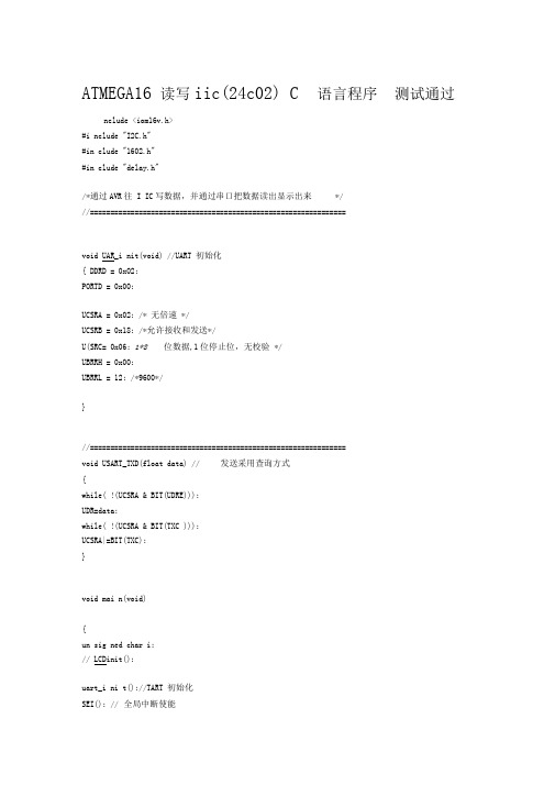
ATMEGA16 读写iic(24c02) C 语言程序测试通过nclude <iom16v.h>#i nclude "I2C.h"#in clude "1602.h"#in clude "delay.h"/*通过AVR往I IC写数据,并通过串口把数据读出显示出来*///===============================================================void UAR_i nit(void) //UART 初始化{ DDRD = 0x02;PORTD = 0x00;UCSRA = 0x02; /* 无倍速*/UCSRB = 0x18; /*允许接收和发送*/U(SRC= 0x06; 1*8位数据,1位停止位,无校验*/UBRRH = 0x00;UBRRL = 12; /*9600*/}//===============================================================void USART_TXD(float data) // 发送采用查询方式{while( !(UCSRA & BIT(UDRE)));UDR=data;while( !(UCSRA & BIT(TXC )));UCSRA|=BIT(TXC);}void mai n(void){un sig ned char i;// LCDinit();uart_i ni t();//TART 初始化SEI(); // 全局中断使能while(1){/*I2C_Write('n',0x00); I2C_Write('c',0x01); I2C_Write('e',0x02);I2C_Write('p',0x03); I2C_Write('u',0x04);*/ i=I2C_Read(0x00); //LCD_write_char(0,0,i); USART_TXD(i); i=I2C_Read(0x01);//LCD_write_data(i); USART_TXD(i); i=I2C_Read(0x02); //LCD_write_data(i); USART_TXD(i);i=I2C_Read(0x03); //LCD_write_data(i); USART_TXD(i); i=I2C_Read(0x04); //LCD_write_data(i); USART_TXD(i);}}/* 上面上主函数部分*/#include <macros.h>#include "delay.h"//I2C 状态定义//MT 主方式传输MR 主方式接受#define START 0x08#define RE_START 0x10#define MT_SLA_ACK 0x18 #define MT_SLA_NOACK 0x20 #define MT_DATA_ACK 0x28 #defineMT_DATA_NOACK 0x30 #define MR_SLA_ACK 0x40 #define MR_SLA_NOACK 0x48 #define MR_DATA_ACK 0x50 #define MR_DATA_NOACK 0x58#define RD_DEVICE_ADDR 0xA1 // 前4位器件固定,后三位看连线,最后1位是读写指令位#define WD_DEVICE_ADDR 0xA0//常用TWI操作(主模式写和读)#define Start() (TWCR=(1<<TWINT)|(1<<TWSTA)|(1<<TWEN)) // 启动I2C #define Stop()(TWCR=(1<<TWINT)|(1<<TWSTO)|(1<<TWEN)) // 停止I2C #define Wait() {while(!(TWCR&(1<<TWINT)));} // 等待中断发生#define TestAck() (TWSR&0xf8) // 观察返回状态#define SetAck (TWCR|=(1<<TWEA)) // 做出ACK应答#define SetNoAck (TWCR&=~(1<<TWEA)) // 做出Not Ack 应答#define Twi() (TWCR=(1<<TWINT)|(1<<TWEN)) // 启动I2C#define Write8Bit(x) {TWDR=(x);TWCR=(1<<TWINT)|(1<<TWEN);} // 写数据到TWDRunsigned char I2C_Write(unsigned char Wdata,unsigned char RegAddress); unsigned charI2C_Read(unsigned RegAddress);/*********************************************I2C 总线写一个字节返回0: 写成功返回1: 写失败**********************************************/unsigned char I2C_Write(unsigned char Wdata,unsigned char RegAddress){Start(); //I2C 启动Wait();if(TestAck()!=START)return 1; //ACKWrite8Bit(WD_DEVICE_ADDR); // 写I2C 从器件地址和写方式Wait(); if(TestAck()!=MT_SLA_ACK) return 1; //ACKWrite8Bit(RegAddress); // 写器件相应寄存器地址Wait();if(TestAck()!=MT_DATA_ACK)return 1; //ACKWrite8Bit(Wdata); // 写数据到器件相应寄存器Wait();if(TestAck()!=MT_DATA_ACK)return 1; //ACKStop(); //I2C 停止delay_nms(10); // 延时return 0;}/*********************************************I2C 总线读一个字节返回0: 读成功返回1: 读失败**********************************************/unsigned char I2C_Read(unsigned RegAddress){ unsigned char temp;Start();//I2C 启动Wait();if (TestAck()!=START) return 1; //ACKWrite8Bit(WD_DEVICE_ADDR); // 写I2C 从器件地址和写方式Wait(); if (TestAck()!=MT_SLA_ACK) return 1; //ACKWrite8Bit(RegAddress); // 写器件相应寄存器地址Wait();if (TestAck()!=MT_DATA_ACK) return 1;Start(); //I2C 重新启动Wait();if (TestAck()!=RE_START) return 1;Write8Bit(RD_DEVICE_ADDR); // 写I2C 从器件地址和读方式Wait(); if(TestAck()!=MR_SLA_ACK)return 1; //ACKTwi(); // 启动主I2C 读方式Wait(); if(TestAck()!=MR_DATA_NOACK) return 1; //ACKtemp=TWDR;// 读取I2C 接收数据Stop();//l2C 停止return temp;}/*以上是IlC.h头文件部分,需要对照技术文档好好研究*/延时函数编译器:I CC-AVR V6.31A 日期:2005-11-24 20:29:57 目标芯片:M16 时钟:8.0000M Hz作者:arche ng504------------------------------------------------- */#ifndef __delay_h#defi ne __delay_hvoid delay_ nus(un sig ned int n);void delay_ nms(un sig ned int n);void delay_1us(void);void delay_1ms(void);void delay_1us(void) //1us 延时函数{asm( "n op");}void delay_ nus(un sig ned int n) 〃N us 延时函数{un sig ned in t i=0;for (i=0;i <n ;i++)delay_1us();}void delay_1ms(void) //1ms 延时函数{un sig ned in t i;for (i=0;i<1140;i++);}void delay_ nms(un sig ned int n) //N ms 延时函数{un sig ned in t i=0;for (i=0;i <n ;i++)delay_1ms();}#en dif/*以上是delay.h 部分,再加上IIC中自带的iom16v.h和macros.h就可以编译通过*//*注意点:本程序在实验板ATMEGA1上测试通过,在示波器把SCL, SDA信号线有数据,移值到自己电路上可以放心使用,在ATMEGA3上一样使用,本人24C02的A2, A1, A0都是接地,若地址不一样,在程序相应位置改一下就可以,串口上调试单片机的基础,所以它一定要会用*//*本程序调试软件环境是ICC6.31*/。
i2c波形通过电平转换后异常
i2c波形通过电平转换后异常【导言】I2C(Inter-Integrated Circuit)是一种常用的串行通信协议,用于在电子设备之间传输数据。
作为一种主从式通信协议,I2C使用两条线(称为SDA和SCL)实现多个设备通过总线相互通信。
然而,在实际应用中,由于各种原因,如电压不稳定、线缆质量差、接触不良等,i2c波形可能会出现异常。
特别是在电平转换过程中,异常情况更容易发生。
本文将探讨i2c波形通过电平转换后的异常情况,并提供解决方案。
【正文】1. 异常现象及原因通过电平转换将I2C信号从5V转换为3.3V或其他不同的电压级别时,可能会出现以下异常情况:1.1 压摆率减慢由于电平转换电路可能引入额外的电容负载,I2C波形在上升沿和下降沿的压摆率可能会减慢。
这可能导致信号的传输速率降低,甚至使其无法达到预期的速率要求。
1.2 信号失真如果电平转换电路的响应时间不足或电压变化不平稳,可能会导致I2C 信号的失真。
信号失真可能表现为波形的不规则变形,甚至是部分波形丢失。
这种情况会导致通信错误,数据传输的准确性受到损害。
1.3 电源噪声电平转换电路引入的电容和电阻可能会引起电源噪声。
这些噪声可能会干扰I2C信号的传输,导致数据的错误或丢失。
1.4 传输延迟由于电平转换电路的存在,I2C信号的传输可能会有一定的延迟。
这种延迟可能会导致在实时应用中出现问题,如数据同步不匹配或信号超时。
2. 解决方案要解决通过电平转换后的I2C波形异常问题,可以采取以下措施:2.1 选择合适的电平转换器根据实际应用需求,选择性能良好的电平转换器。
电平转换器应具备快速响应、低电压降和低功耗的特点,以确保信号的准确转换和传输。
2.2 优化线路设计优化I2C线路布局和连接方式,尽量减少电流回路长度,避免浪费功耗和信号损耗。
使用优质的线缆和连接器,保证信号的可靠传输。
2.3 添加滤波电路在电平转换器的输入和输出端添加恰当的滤波电路,以抑制电源噪声和信号干扰。
I2C读写流程范文
I2C读写流程范文I2C(Inter-Integrated Circuit)是一种串行通信协议,用于在集成电路之间进行短距离的通信。
这个协议由飞利浦公司(现在的恩智浦半导体)在20世纪80年代初引入。
I2C由两根线构成,分别是时钟线(SCL)和数据线(SDA),其中时钟线由主设备控制发送,数据线用于主设备和从设备之间的双向数据传输。
I2C协议支持多主设备和多从设备的并行连接。
1.初始化:a.设置I2C总线的时钟频率。
b.初始化GPIO端口,将SCL和SDA设置为输出模式,并将它们拉高。
2.发送设备地址:a.主设备发送起始信号,即在SCL线上拉低SDA线,表示数据的传输即将开始。
b.主设备发送设备地址和读写位(0表示写,1表示读)到SDA线。
设备地址是从设备的标识符,主设备用它来选择要通信的从设备。
c.主设备发送读写位确认信号,即主设备将SCL线拉低一段时间,然后释放,之后从设备根据读写位作出响应。
3.发送数据:a.主设备将要发送的数据写入到SDA线上。
b.主设备发送数据确认信号,即主设备将SCL线拉低一段时间,然后释放。
c.从设备接收数据,并根据接收情况作出响应。
4.接收数据:a.主设备发出重新起始信号,即在SCL线上拉低SDA线,然后释放。
b.主设备发送设备地址和读写位到SDA线,指示要读取数据的从设备。
c.主设备发送读写位确认信号,即主设备将SCL线拉低一段时间,然后释放。
d.从设备将要发送的数据写入到SDA线上。
e.主设备接收数据,并根据接收情况作出响应。
5.终止通信:a.主设备发出停止信号,即在SCL线上拉低SDA线,然后释放。
b.从设备根据停止信号作出响应。
以上就是I2C读写的基本流程。
需要注意的是,I2C是一种同步通信协议,所有的数据传输都是通过时钟线同步的。
主设备控制时钟信号的频率,从设备负责根据时钟信号的变化作出响应。
通过这种方式,可以实现多个设备在同一总线上进行通信。
I2C总线编程实例(k1-k4:写入、读取、加+、清零)【EEPROM-AT24C02】

I2C总线编程实例(k1-k4:写⼊、读取、加+、清零)【EEPROM-AT24C02】(1)AT24C02是⼀种EEPROM元器件,是⼀种只读寄存器,断电保持,可保存数据100年, 是⼀种可擦除读写的芯⽚,相当于ROM硬盘,在下⾯实验中充当从机⾓⾊;(2)51在下⾯实验中充当主机⾓⾊;(3)在IIC总线标准协议上,进⾏51单⽚机(主机)和AT24C02(从机)的相互读写数据的操作。
⼩结:51单⽚机和各种EEPROM芯⽚之间可以通过IIC总线标准协议进⾏数据交互(通信)的。
实验:四个独⽴按键对应四个不同的功能,k1:将数据写⼊单⽚机,断电保存k2:读取上次保存的数据,断电后仍可读取上次保存的数据k3:当前数据+1k4:当前数据清零------------------------------------------------------------- 采⽤多⽂件的框架模式 -------------------------------------------------------------i2c.h:/*这个⽂件进⾏宏定义:定义I2C串⾏总线的相关数据端⼝、⽅法函数,以及定义⼀些使⽤频率较⾼的元素*/#ifndef _I2C_H_ // 如果没有定义宏#define _I2C_H_ // 定义⼀个宏// 需要⽤到51单⽚机的管脚,所以需要引⼊库⽂件#include <reg52.h>// 查单⽚机原理图可知(其中,SCL是时钟线,SDA是数据线)sbit SCL=P2^1;sbit SDA=P2^0;/* 相关函数 */// I2C的起始信号函数void I2cStart();// I2C的终⽌信号函数void I2cStop();// I2C发送(写⼊)字节函数,成功返回1,失败返回0unsigned char I2cSendByte(unsigned char dat);// I2C接收(读取)字节函数,返回读取的数据unsigned char I2cReadByte();// AT24C02芯⽚的写⼊数据函数void At24c02Write(unsigned char addr, unsigned dat);// AT24C02芯⽚的读取数据函数,返回读取的数据unsigned char At24c02Read(unsigned char addr);#endif // 结束i2c.c:/* 这个⽂件专门针对I2C模块的编程,其他模块可以新建另外⼀个⽂件 */#include <i2c.h> // 引⼊I2C的库⽂件/******************************************************************************** 函数名 : Delay10us()* 函数功能 : 延时10us* 输⼊ : ⽆* 输出 : ⽆*******************************************************************************/void Delay10us() //误差 0usunsigned char a,b;for(b=1;b>0;b--)for(a=2;a>0;a--);}/******************************************************************************** 函数名 : I2cStart()* 函数功能 : 起始信号:在SCL时钟信号在⾼电平期间SDA信号产⽣⼀个下降沿* 输⼊ : ⽆* 输出 : ⽆* 备注 : 起始之后SDA和SCL都为0,表⽰总线被主机占⽤*******************************************************************************/void I2cStart(){// 根据各个单⽚机的时序图来写SDA=1;Delay10us();SCL=1;Delay10us(); // 建⽴时间是SDA保持时间>4.7usSDA=0;Delay10us(); // 保持时间是>4usSCL=0;Delay10us();}/******************************************************************************** 函数名 : I2cStop()* 函数功能 : 终⽌信号:在SCL时钟信号⾼电平期间SDA信号产⽣⼀个上升沿* 输⼊ : ⽆* 输出 : ⽆* 备注 : 结束之后保持SDA和SCL都为1;表⽰总线处于空闲状态*******************************************************************************/void I2cStop(){// 根据各个单⽚机的时序图来写SDA=0;Delay10us();SCL=1;Delay10us(); // 建⽴时间是SDA保持时间>4.7usSDA=1;Delay10us(); // 保持时间是>4us}/******************************************************************************** 函数名 : I2cSendByte(unsigned char dat)* 函数功能 : 通过I2C发送⼀个字节。
iic调试方法

iic调试方法IIC调试方法IIC(Inter-Integrated Circuit)是一种常用的串行通信协议,用于在电路板之间传输数据。
在进行IIC调试时,我们需要遵循一定的方法和步骤来确保通信的稳定和可靠性。
本文将介绍一些常用的IIC 调试方法,并对其原理和步骤进行详细说明。
一、IIC调试的基本原理IIC是一种基于硬件的串行通信协议,它由两根信号线组成:SDA (Serial Data Line)和SCL(Serial Clock Line)。
在IIC通信中,数据是通过SDA线传输的,而时钟信号则由SCL线提供。
调试过程中,我们需要确保这两根信号线的稳定性和正确性,以保证数据的准确传输。
二、IIC调试步骤1. 确认硬件连接:首先,我们需要确认IIC设备的硬件连接是否正确。
检查SDA和SCL线是否正确连接到目标设备的对应引脚,并确保电源和地线的连接正常。
2. 配置IIC设备地址:每个IIC设备都有一个唯一的地址,用于在总线上进行识别和通信。
在调试过程中,我们需要正确配置目标设备的地址。
通常可以通过读取设备的说明书或寄存器设置来获取正确的地址信息。
3. 设置IIC通信速率:IIC通信速率也称为波特率,决定了数据传输的速度。
根据目标设备的规格要求,我们需要设置适当的通信速率。
通常情况下,较低的通信速率可以提高通信的可靠性。
4. 编写测试代码:根据目标设备的功能和通信协议,我们需要编写相应的测试代码。
测试代码应包括初始化IIC设备、发送和接收数据等操作。
在编写代码时,我们可以使用现成的IIC库或驱动程序,以简化开发过程。
5. 运行调试代码:将编写好的测试代码烧录到目标设备上,并运行调试代码。
通过监测SDA和SCL线上的信号波形,我们可以判断通信是否正常。
如果出现通信错误或数据传输异常,我们可以通过调试工具或逐步调试的方法,逐个排查问题,找出并解决故障。
6. 数据验证和分析:在通信正常的情况下,我们可以通过发送特定的测试数据来验证目标设备的功能是否正常。
EEPROMI2C操作说明

EEPROMI2C操作说明EEPROM (Electrically Erasable Programmable Read-Only Memory)是一种非易失性存储器,可以通过电子方式擦除和编程,同时可以通过I2C总线进行操作。
本文将详细介绍EEPROM的I2C操作说明。
I2C(Inter-Integrated Circuit)是一种串行通信接口协议,可以在多个设备之间进行通信。
在EEPROM的I2C操作中,需要了解以下几个重要的概念和步骤。
1.设备地址:每个通过I2C连接的设备都有一个唯一的设备地址。
在EEPROM的I2C操作中,需要使用设备地址来与EEPROM进行通信。
2.起始条件和停止条件:I2C通信中,起始条件表示通信的开始,停止条件表示通信的结束。
起始条件由一个高电平到低电平的SCL上升沿和一个低电平的SDA下降沿组成,停止条件由一个低电平到高电平的SCL上升沿和一个高电平的SDA上升沿组成。
3. 数据传输:I2C通信中,数据可以以字节的形式进行传输。
每个字节由8个bit组成,包括7个数据位和1个校验位。
在进行EEPROM的I2C操作时,通常需要经过以下几个步骤:1.发送起始条件:将SCL和SDA引脚拉高,然后将SDA引脚拉低,形成起始条件。
2.发送设备地址和写命令:根据EEPROM的设备地址,将设备地址和写命令(0)发送到SDA引脚。
3.发送要写入的地址:将要写入数据的地址发送到SDA引脚。
4.发送数据:将要写入的数据发送到SDA引脚。
5.发送停止条件:将SCL引脚拉高,然后将SDA引脚拉高,形成停止条件。
实际的EEPROM的I2C操作可能还包括以下一些操作:1.读操作:通过发送读命令(1)和读取数据的地址,可以从EEPROM 中读取数据。
读操作与写操作类似,只是需要在发送设备地址时,将写命令(0)改为读命令(1)。
2.擦除操作:EEPROM的主要特点之一是可以擦除数据。
通过发送擦除命令和要擦除的数据的地址,可以将指定数据段擦除为初始值。
78K0系列用户手册(指令集)
To our customers,Old Company Name in Catalogs and Other DocumentsOn April 1st, 2010, NEC Electronics Corporation merged with Renesas Technology Corporation, and Renesas Electronics Corporation took over all the business of both companies. Therefore, although the old company name remains in this document, it is a valid Renesas Electronics document. We appreciate your understanding.Renesas Electronics website: April 1st, 2010Renesas Electronics CorporationIssued by: Renesas Electronics Corporation ()Send any inquiries to /inquiry.Notice1. All information included in this document is current as of the date this document is issued. Such information, however, issubject to change without any prior notice. Before purchasing or using any Renesas Electronics products listed herein, please confirm the latest product information with a Renesas Electronics sales office. Also, please pay regular and careful attention to additional and different information to be disclosed by Renesas Electronics such as that disclosed through our website.2. Renesas Electronics does not assume any liability for infringement of patents, copyrights, or other intellectual property rightsof third parties by or arising from the use of Renesas Electronics products or technical information described in this document.No license, express, implied or otherwise, is granted hereby under any patents, copyrights or other intellectual property rights of Renesas Electronics or others.3. You should not alter, modify, copy, or otherwise misappropriate any Renesas Electronics product, whether in whole or in part.4. Descriptions of circuits, software and other related information in this document are provided only to illustrate the operation ofsemiconductor products and application examples. You are fully responsible for the incorporation of these circuits, software, and information in the design of your equipment. Renesas Electronics assumes no responsibility for any losses incurred by you or third parties arising from the use of these circuits, software, or information.5. When exporting the products or technology described in this document, you should comply with the applicable export controllaws and regulations and follow the procedures required by such laws and regulations. You should not use RenesasElectronics products or the technology described in this document for any purpose relating to military applications or use by the military, including but not limited to the development of weapons of mass destruction. Renesas Electronics products and technology may not be used for or incorporated into any products or systems whose manufacture, use, or sale is prohibited under any applicable domestic or foreign laws or regulations.6. Renesas Electronics has used reasonable care in preparing the information included in this document, but Renesas Electronicsdoes not warrant that such information is error free. Renesas Electronics assumes no liability whatsoever for any damages incurred by you resulting from errors in or omissions from the information included herein.7. Renesas Electronics products are classified according to the following three quality grades: “Standard”, “High Quality”, and“Specific”. The recommended applications for each Renesas Electronics product depends on the product’s quality grade, as indicated below. You must check the quality grade of each Renesas Electronics product before using it in a particularapplication. You may not use any Renesas Electronics product for any application categorized as “Specific” without the prior written consent of Renesas Electronics. Further, you may not use any Renesas Electronics product for any application for which it is not intended without the prior written consent of Renesas Electronics. Renesas Electronics shall not be in any way liable for any damages or losses incurred by you or third parties arising from the use of any Renesas Electronics product for an application categorized as “Specific” or for which the product is not intended where you have failed to obtain the prior written consent of Renesas Electronics. The quality grade of each Renesas Electronics product is “Standard” unless otherwiseexpressly specified in a Renesas Electronics data sheets or data books, etc.“Standard”: Computers; office equipment; communications equipment; test and measurement equipment; audio and visual equipment; home electronic appliances; machine tools; personal electronic equipment; and industrial robots.“High Quality”: Transportation equipment (automobiles, trains, ships, etc.); traffic control systems; anti-disaster systems; anti-crime systems; safety equipment; and medical equipment not specifically designed for life support.“Specific”: Aircraft; aerospace equipment; submersible repeaters; nuclear reactor control systems; medical equipment or systems for life support (e.g. artificial life support devices or systems), surgical implantations, or healthcareintervention (e.g. excision, etc.), and any other applications or purposes that pose a direct threat to human life.8. You should use the Renesas Electronics products described in this document within the range specified by Renesas Electronics,especially with respect to the maximum rating, operating supply voltage range, movement power voltage range, heat radiation characteristics, installation and other product characteristics. Renesas Electronics shall have no liability for malfunctions or damages arising out of the use of Renesas Electronics products beyond such specified ranges.9. Although Renesas Electronics endeavors to improve the quality and reliability of its products, semiconductor products havespecific characteristics such as the occurrence of failure at a certain rate and malfunctions under certain use conditions. Further, Renesas Electronics products are not subject to radiation resistance design. Please be sure to implement safety measures to guard them against the possibility of physical injury, and injury or damage caused by fire in the event of the failure of aRenesas Electronics product, such as safety design for hardware and software including but not limited to redundancy, fire control and malfunction prevention, appropriate treatment for aging degradation or any other appropriate measures. Because the evaluation of microcomputer software alone is very difficult, please evaluate the safety of the final products or system manufactured by you.10. Please contact a Renesas Electronics sales office for details as to environmental matters such as the environmentalcompatibility of each Renesas Electronics product. Please use Renesas Electronics products in compliance with all applicable laws and regulations that regulate the inclusion or use of controlled substances, including without limitation, the EU RoHS Directive. Renesas Electronics assumes no liability for damages or losses occurring as a result of your noncompliance with applicable laws and regulations.11. This document may not be reproduced or duplicated, in any form, in whole or in part, without prior written consent of RenesasElectronics.12. Please contact a Renesas Electronics sales office if you have any questions regarding the information contained in thisdocument or Renesas Electronics products, or if you have any other inquiries.(Note 1) “Renesas Electronics” as used in this document means Renesas Electronics Corporation and also includes its majority-owned subsidiaries.(Note 2) “Renesas Electronics product(s)” means any product developed or manufactured by or for Renesas Electronics.用户手册适用于78K/0系列78K/0系列指令©NEC Electronics China 2007日本印制文档编号.U12326CA4V0UM00(第四版)发行日期2007年7月NCP(K)[备忘录]用户手册U12326CA4V0UM 2CMOS设备的注释①ESD防护措施如果MOS设备周围有强电场,将会击穿氧化栅极,从而影响设备的运行。
- 1、下载文档前请自行甄别文档内容的完整性,平台不提供额外的编辑、内容补充、找答案等附加服务。
- 2、"仅部分预览"的文档,不可在线预览部分如存在完整性等问题,可反馈申请退款(可完整预览的文档不适用该条件!)。
- 3、如文档侵犯您的权益,请联系客服反馈,我们会尽快为您处理(人工客服工作时间:9:00-18:30)。
78K与MAX11068 IIC通讯C程序#include "MAX11068_CMD.h"/***-----------------------------------------------------------------------------**** Abstract:** This function stops the IIC11 operation.**** Parameters:** None**** Returns:** None****-----------------------------------------------------------------------------*/void IIC11_Stop(void){/* Stop transfer */ST1 |= _0002_SAU_CH1_STOP_TRG_ON; /* disable IIC11 */IICMK11 = 1U; /* disable INTIIC11 */}/***-----------------------------------------------------------------------------**** Abstract:** This function starts IIC11 condition.**** Parameters:** None**** Returns:** None****-----------------------------------------------------------------------------*/void IIC11_StartCondition(void){SO1 &= ~_0002_SAU_CH1_DATA_OUTPUT_1; /* clear IIC11 SDA */ NOP();NOP();SOE1 |= _0002_SAU_CH1_OUTPUT_ENABLE; /* enable IIC11 out */ SO1 &= ~_0200_SAU_CH1_CLOCK_OUTPUT_1; /* clear IIC11 SCL */ NOP();SS1 |= _0002_SAU_CH1_START_TRG_ON; /* enable IIC11 */}/***-----------------------------------------------------------------------------**** Abstract:** This function stops IIC11 condition.**** Parameters:** None**** Returns:** None****-----------------------------------------------------------------------------*/void IIC11_StopCondition(void){ST1 |= _0002_SAU_CH1_STOP_TRG_ON; /* disable IIC11 */SOE1 &= ~_0002_SAU_CH1_OUTPUT_ENABLE; /* disable IIC11 out */ NOP();SO1 &= ~_0002_SAU_CH1_DATA_OUTPUT_1; /* clear IIC11 SDA */ NOP();NOP();NOP();SO1 |= _0200_SAU_CH1_CLOCK_OUTPUT_1; /* set IIC11 SCL */NOP();NOP();NOP();SO1 |= _0002_SAU_CH1_DATA_OUTPUT_1; /* set IIC11 SDA */}UCHAR HELLOALL(void) /*set slave device address*/{UCHAR addr;UCHAR error_cnt = 0;addr = Address_HELLOALL & 0xFEU;/*** Change Communication mode to Tx*/Change_IIC_Communication_Mode(Transmission);retry:/**step 1. check IIC bus busy or free*///IIC11_StopCondition();/**step 2. send start signal*/IIC11_StartCondition();/**step 3. send data*/SDR11L = addr;/*** wait data transmite over!*/if(!Check_Interrupt_Status()){return 0;}/**step 4. check slave device ack*/if( !Check_ACK() ){//ACK_ERROR();//return 0;error_cnt ++;if(error_cnt > 10){return 0;}goto retry;}/**step 5. send stop signal*/IIC11_StopCondition();return 1;/************ END ***********/}UCHAR ROLLCALL(UCHAR *data_buff, UCHAR data_len) /*get slave device address and count slave device number*/{UINT i;UCHAR addr;addr = Address_Broadcast_W;/*** Change Communication mode to Tx*/Change_IIC_Communication_Mode(Transmission);/*** step 1. Check IIC busy or free*///IIC11_StopCondition();/*** step 2. Send start signal*/IIC11_StartCondition();/*** step 3. Send data (broadcast address)*/SDR11L = addr;/*** wait data transmite over!*/if(!Check_Interrupt_Status()){return 0;}/*** step 4. Check salve device ACK*/if(!Check_ACK()){//ACK_ERROR();return 0;}/*** step 5. Send data (slave device register address) */SDR11L = _01_MAX11068_ADDRESS_REGISTER;/*** wait data transmite over!*/if(!Check_Interrupt_Status()){return 0;}/*** step 6. Check slave device ACK*/if(!Check_ACK()){//ACK_ERROR();return 0;}/*** step 7. Send ReStart*/RESTART();/*** step 8. set new broadcast address and send data */addr = Address_Broadcast_R;SDR11L = addr;/*** wait data transmite over!*/if(!Check_Interrupt_Status()){return 0;}/*** step 9. Check slave device ACK*/if(!Check_ACK()){//ACK_ERROR();return 0;}/*** step 10. Change SCR to recieve mode*/Change_IIC_Communication_Mode(Reception);/*** step 11. Receive data from slave device*/i = 0;while(i < data_len){/*Writing dummy data to SDR 0xFF*/SDR11L = 0xff;/* Transfer end interrupt generated? */if(!Check_Interrupt_Status()) //when data is transmited over, there is a int happened {// interrupt errorreturn 0;}/* Reading SDR */data_buff[i] = SDR11L; //recieve datai ++;}/*** step 12. Send Stop*/IIC11_StopCondition();return data_buff[data_len - 2];}UCHAR SETLASTADDRESS(UCHAR last_device_adr) /*set last slave device address for lower device*/{UCHAR i;UCHAR buffer[8];buffer[0] = Address_Broadcast_W; /*Send broadcast address as write mode*/buffer[1] = 0x01; /*send ADDRESS Register address*/buffer[2] = 0xA0; /*lower 8 bit device address*/buffer[3] = last_device_adr; /*higher 8 bit: the number of device*/buffer[4] = PEC_Calculation(buffer,4);/*Send PEC byte*//*** Change Communication mode to Tx*/Change_IIC_Communication_Mode(Transmission);/*** step 1. Check IIC bus busy or free*///IIC11_StopCondition();/*** step 3. Send Start and delay*/IIC11_StartCondition();/*** step 3. Send Data : address+w, ADDRESS Register, LSB, MSB, PEC*/for(i=0;i<5;i++)SDR11L = buffer[i];/* Transfer end interrupt generated? */if(!Check_Interrupt_Status()) //when data is transmited over, there is a int happened{// interrupt errorreturn 0;}if(!Check_ACK()){//ACK_ERROR();return 0;}wait(delay_t);}/*** step 4. Send Stop*/IIC11_StopCondition();return 1;}UCHAR READALL(UCHAR Register_address, UCHAR *data_buff, UCHAR data_len)//NOTE: data_buff[0] not use{UINT i;UCHAR flag;UCHAR receive_over_flag;/*** Change Communication mode to Tx*/Change_IIC_Communication_Mode(Transmission);/*** step 1. Check IIC bus busy or free*///IIC11_StopCondition();/*** step 2. Send Start*/IIC11_StartCondition();/*** step 3. Send Data : broadcast address data */SDR11L = Address_Broadcast_W;/*** wait data transmite over!*/if(!Check_Interrupt_Status()){//Interrupt errorreturn 0;}/*** step 4. Check ACK and Wait*/if(!Check_ACK()){//ACK_ERROR();return 0;}/*** step 5. Send Data : register address data */SDR11L = Register_address;/*** wait data transmite over!*/if(!Check_Interrupt_Status()){//Interrupt errorreturn 0;}/*** step 6. Check ACK and Wait*/if(!Check_ACK()){//ACK_ERROR();return 0;}/*** step 7. Send ReStart*/RESTART();/*** step 9. Send Broadcast address*/SDR11L = Address_Broadcast_R;/*** wait data transmite over!*/if(!Check_Interrupt_Status()){//Interrupt errorreturn 0;}/*** step 10. Check ACK*/if(!Check_ACK()){//ACK_ERROR();return 0;}/*** step 11. Change communication as recive mode *//*** Change Communication mode to Rx*/Change_IIC_Communication_Mode(Reception);** step 12. Recive Data*/receive_over_flag = 0;i = 0;flag = 0;while(i <= data_len){/*RECEIVE SLAVE DATA UNTIL CONSECUTIVE 0xFF BYTES,THEN NACK THE SLAVE*/ if(i == data_len) /*last byte recieve ?*/{SOE1 &= ~_0002_SAU_CH1_OUTPUT_ENABLE; /* disable IIC11 out */SO1 &= ~_0002_SAU_CH1_DATA_OUTPUT_1; /* clear IIC11 SDA */NOP();NOP();NOP();SO1 &= ~_0200_SAU_CH1_CLOCK_OUTPUT_1; /* clear IIC11 SCL */NOP();NOP();NOP();SO1 |= _0002_SAU_CH1_DATA_OUTPUT_1; /* set IIC11 SDA */ST1 |= _0002_SAU_CH1_STOP_TRG_ON; /* disable IIC11 */NOP();break;}/*Writing dummy data to SDR 0xFF*/SDR11L = 0xff;/* Transfer end interrupt generated? */if(!Check_Interrupt_Status()) //when data is transmited over, there is a int happened {// interrupt errorreturn 0;}wait(delay_t);/* Reading SDR */data_buff[i] = SDR11L; //recieve datai ++;/*** step 13. Send stop*/IIC11_StopCondition();return data_buff[i -2];}//NOTE: data_buff only used bit 0,1;UCHAR WRITEALL(UCHAR register_address, UCHAR LSB, UCHAR MSB){UINT i;UCHAR buffer[5];buffer[0] = Address_Broadcast_W; /*Send broadcast address as write mode*/ buffer[1] = register_address; /*send Register address*/buffer[2] = LSB; /*lower 8 bit device address*/buffer[3] = MSB; /*higher 8 bit: the number of device*/buffer[4] = PEC_Calculation(buffer,4); /*Send PEC byte*//*** Change Communication mode to Tx*/Change_IIC_Communication_Mode(Transmission);/*** step 1. Check IIC bus busy or free*///IIC11_StopCondition();/*** step 2. Send Start*/IIC11_StartCondition();/*** step 3. Send Broadcast address*/SDR11L = Address_Broadcast_W; /*send MAX11068 broadcast address*//*** wait data transmite over!if(!Check_Interrupt_Status()){//Interrupt errorreturn 0;}if(!Check_ACK()){//ACK_ERROR();return 0;}/*** step 4. Send register address*/SDR11L = register_address;/*** wait data transmite over!*/if(!Check_Interrupt_Status()){//Interrupt errorreturn 0;}if(!Check_ACK()){//ACK_ERROR();return 0;}/*** step 4. Send data*/for(i=0; i<5; i++) /* 5 is datalength */{SDR11L = buffer[i];/* Transfer end interrupt generated? */if(!Check_Interrupt_Status()) //when data is transmited over, there is a int happened {// interrupt errorreturn 0;}if(!Check_ACK()){//ACK_ERROR();return 0;}wait(delay_t);}/*** step 8. Send stop*/IIC11_StopCondition();return 1;}UCHAR WRITEDEVICE(UCHAR cmd_device_address, UCHAR register_adr, UCHAR *data_buff)//NOTE: data_buff only bit 0,1,2 inuse{UCHAR i;UCHAR buffer[8];/*** Change Communication mode to Tx*/Change_IIC_Communication_Mode(Transmission);/*** step 1. Check IIC bus busy or free*///IIC11_StopCondition();/*** step 2. Send Start*/IIC11_StartCondition(); /*send a START*//*** step 4. Send buffer data*/buffer[0] = cmd_device_address; /*send WRITEDEVICE Command*/buffer[1] = register_adr; /*send Register address*/buffer[2] = data_buff[0]; /*lower 8 bit*/buffer[3] = data_buff[1]; /*higher 8 bit*/buffer[4] = PEC_Calculation(buffer,4);/*** step 5. Write Data to Device*/for(i=0;i<5;i++){SDR11L = buffer[i];/* Transfer end interrupt generated? */if(!Check_Interrupt_Status()) //when data is transmited over, there is a int happened{// interrupt errorreturn 0;}if(!Check_ACK()){//ACK_ERROR();return 0;}wait(delay_t);}/*** step 8. Send stop*/IIC11_StopCondition();return 1;}/******************************************************* Abstract:** This function**** Parameters:** None**** Returns:** None*******************************************************/void RESTART(void){ST1 |= _0002_SAU_CH1_STOP_TRG_ON; /* disable IIC11 */ SOE1 &= ~_0002_SAU_CH1_OUTPUT_ENABLE; /* disable IIC11 out *///SO1 &= ~_0002_SAU_CH1_DATA_OUTPUT_1; /* clear IIC11 SDA */SO1 |= _0200_SAU_CH1_CLOCK_OUTPUT_1; /* set IIC11 SCL */wait(delay_t);SO1 |= _0002_SAU_CH1_DATA_OUTPUT_1; /* set IIC11 SDA */IIC11_StartCondition();}/******************************************************* Abstract:** This function check the IIC busy or free**** Parameters:** USHORT Tx_or_Rx**** Returns:** None*******************************************************/UCHAR Check_Interrupt_Status(void){USHORT i = 0;while(!IICIF11) /*check interrupt flag*/{i++;if(i == 0xff) /*how long does it suitable ?*/{return 0; // interrupt error!}}IICIF11 = 0x0U;return 1; //interrupt OK!}/******************************************************* Abstract:** This function check the IIC busy or free**** Parameters:** USHORT Tx_or_Rx**** Returns:** None*******************************************************/void Change_IIC_Communication_Mode(USHORT Tx_or_Rx){if(Tx_or_Rx == Transmission){if((SCR11 & 0xC000) != Transmission){ST1 |= _0002_SAU_CH1_STOP_TRG_ON; /* disable IIC11 */NOP();SCR11 &= ~_C000_SAU_RECEPTION_TRANSMISSION;SCR11 |= _8000_SAU_TRANSMISSION;NOP();SS1 |= _0002_SAU_CH1_START_TRG_ON;}}if(Tx_or_Rx == Reception){if((SCR11 & 0xC000) != Reception){ST1 |= _0002_SAU_CH1_STOP_TRG_ON; /* disable IIC11 */NOP();SCR11 &= ~_C000_SAU_RECEPTION_TRANSMISSION;SCR11 |= _4000_SAU_RECEPTION;NOP();SS1 |= _0002_SAU_CH1_START_TRG_ON; /* enable IIC11 */ }}}/******************************************************* Abstract:** This function check the slave device ack signal**** Parameters:** None**** Returns:** None*******************************************************/UCHAR Check_ACK(void){/*when ACK is not detected during IIC transmission, PEF bit of SSR11 is set */ if(SSR11 & 0x0002){return 0; // check ACK ERROR!} elsereturn 1; // check SCK OK!}/******************************************************* Abstract:** This function check the IIC busy or free**** Parameters:** USHORT Tx_or_Rx**** Returns:** None*******************************************************/void wait(UINT number){while(number--){NOP();}}/******************************************************* Abstract:** This function PEC_Calculation**** Parameters:** ptr: point to databuffer** len: data length** Returns:** None*******************************************************/UCHAR PEC_Calculation(UCHAR * ptr,UCHAR len) // OK! 0x40,0x09,0xff,0x03 out CRC=0x7F {UCHAR crc;UCHAR i;crc = 0;while(len--){crc ^= *ptr++;for(i = 0;i < 8;i++){if(crc & 0x80 )crc = (crc << 1) ^ 0x07;elsecrc <<= 1;}}return crc;}。