STS升版说明2003121
2003功能表各指令项目之功能描述
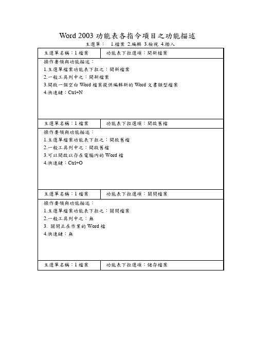
操作要領與功能.一般工具列中之:開啟舊檔
3.可以開啟以存在電腦內的Word檔
4.快速鍵:Ctrl+O
主選單名稱:1檔案
功能表下拉選項:關閉檔案
操作要領與功能描述:
1.主選單檔案功能表下拉之:關閉檔案
2.一般工具列中之:無
3.關閉正在作業的Word檔
Word 2003功能表各指令項目之功能描述
主選單:1.檔案2.編輯3.檢視4.插入
主選單名稱:1檔案
功能表下拉選項:開新檔案
操作要領與功能描述:
1.主選單檔案功能表下拉之:開新檔案
2.一般工具列中之:開新檔案
3.開啟一個空白Word檔案提供編輯新的Word文書類型檔案
4.快速鍵:Ctrl+N
主選單名稱:1檔案
功能表下拉選項:標準模式
操作要領與功能描述:
1.主選單檔案功能表下拉之:標準模式
2.一般工具列中之:無
3.將Word的模式調成標準模式
4.快速鍵:無
主選單名稱:3.檢視
功能表下拉選項:web版面配置
操作要領與功能描述:
1.主選單檔案功能表下拉之:web版面配置
2.一般工具列中之:無
3.可將Word調成web版面配置
3.可以另存一個與目前在用的Word檔的路徑不同之功能
4.快速鍵:F12
主選單名稱:1檔案
功能表下拉選項:另存成網業
操作要領與功能描述:
1.主選單檔案功能表下拉之:另存成網業
2.一般工具列中之:無
3.可以將Word存成網業的模式
4.快速鍵:無
主選單名稱:1檔案
功能表下拉選項:網業預覽
操作要領與功能描述:
最新国质检锅[2003]251号安改维许可规则(1)
![最新国质检锅[2003]251号安改维许可规则(1)](https://img.taocdn.com/s3/m/dab70bd55a8102d277a22fbd.png)
国质检锅[2003]251号安改维许可规则(1)急件国家质量监督检验检疫总局文件国质检锅[2003]251号关于印发《机电类特种设备安装改造维修许可规则(试行)》的通知各省、自治区、直辖市质量技术监督局,各有关单位:为了规范机电类特种设备安装、改造、维修单位的资格许可工作,确保机电类特种设备安装、改造、维修及电梯日常维护保养的质量与安全性能,根据《特种设备安全监察条例》和《特种设备质量监督与安全监察规定》(原国家质量技术监督局令第13号),总局制定了《机电类特种设备安装改造维修许可规则(试行)》。
现印发你们,请认真贯彻执行。
各地质量技术监督部门在执行中,应当按照如下要求处理好以往相关行政许可向本规则转化的工作:一、所有已经取得特种设备安装、改造、维修或电梯日常维护保养资格的企业,应按照本规则规定重新申请相关许可项目。
二、对上述企业进行审查时,执行审查的鉴定评审机构,可使用或借鉴已有的评审结果,但缺少本规则规定的对应项目或审查要求与本规则不一致的,必须予以补充。
三、2004年5月31日前,已取得的相关资格尚在有效期限内,并能够按照本规则规定及时提出相关资格申请的企业,可以从事相应特种设备安装、改造、维修及维护保养工作,不作为无证处理。
四、执行中如发现问题,请及时报总局锅炉压力容器安全监察局。
二〇〇三年八月八日机电类特种设备安装改造维修许可规则(试行)第一章总则第一条为了规范机电类特种设备安装、改造、维修单位的资格许可工作,确保机电类特种设备安装、改造、维修及电梯日常维护保养的质量与安全性能,根据《特种设备安全监察条例》和《特种设备质量监督与安全监察规定》,制定本规则。
第二条凡从事电梯、起重机械、客运索道和大型游乐设施等机电类特种设备(以下统称机电类特种设备)安装、改造、维修和电梯日常维护保养的单位(以下统称施工单位),必须取得《特种设备安装改造维修许可证》(以下简称《许可证》),并在许可的范围内从事相应工作。
2003 奥迪 A6 2.7 T 规格表说明书

Legend A6 2.7 T x = Standard O = Optional P = Package Sedanl 2.7 liter, 250 hp, V6 DOHC bi-turbo engine with direct ignition, electronic turbo boost regulation and 5 valves perx cylinder, ME 7.0 Motronic with electronic throttle controll6-speed manual transmission with synchronized reverse gear xl5-speed automatic transmission with Tiptronic® and DSP (selects from over 200 shift programs to match driverO needs), hill detection capability and new "Sport-mode" settingl quattro® IV - permanent all-wheel drive system with Torsen® TORque SENsing center differential xl Anti-lock Brake System (ABS 5.3) with front and rear Electronic Differential Locks (EDL) and Electronic Brake-forcex Distribution (EBD)l CFC-free (ChloroFlouroCarbon) air conditioning refrigerant xl Fully galvanized steel unibody construction with aluminum hood xl ESP 5.7 - Electronic Stabilization Program with brake assist xl7.5J x 17 inch 5-spoke cast alloy wheels (Standard for Canada)Ol7.5J x 17 inch cross-spoke alloy wheels (Included in Sport Package for Canada)xl235/45 R17 all-season tires (Standard equipment in Canada)Ol235/45 R17 high performance tires (Included in Sport Package for Canada)xl Sport Suspension with: (Included in Sport Package for Canada)x - body lowered 20mm- shocks with 40% increased compression damping- 30% stiffer spring rate- thicker stabilizer barl Space-saving temporary spare tire xl FNRG-60 high-performance, two-pad front brakes xl Four-link front suspension xl Double A-arm rear suspension xl Servotronic® - vehicle speed-sensitive power rack & pinion steering xl Leather covered 3-spoke Sport steering wheel in matching dashboard color xl Tilt and telescopic (manual) adjustable steering column xl 5 MPH (Federal standard) bumpers, painted in body color xl Bumper covers contoured to be flush with body surface and profile xl Protective side moldings, painted in body color xl Body color, flush door handles xl Bright trim around side windows and lower trunk lid xl Body color outside mirrors; left side flat, right side convex xl Heatable windshield washer nozzles xl Metallic and pearl effect paint at no extra charge xl Aluminum door sill strips with "Audi" script xl Visible dual exhaust xl Powerglass slide / tilt sunroof with sunshade Pl Nomenclature: - A6 on rear deck lid - left x - 2.7 T on rear deck lid - right x- Four rings on center of rear deck lid & front grille x- 80 mm quattro® badge on: x rear deck lid - rightfront grille - rightdashboard belt line trim - rightLegend A6 2.7 T x = Standard O = Optional P = Package Sedanl Halogen headlights, 3-way lights, including integrated ellipsoid low beam xl Xenon high intensity, low and high beam headlights Pl Two front fog lights located in lower front bumper (fog lights as daytime running lights for Canadian vehicles) xl Two rear fog lights xl High pressure headlight washers, retractable, flush with bumper xl Red taillight lenses with amber lenses for turn signal x l"Puddle" lights in all four doors xl White side turn indicator lights in front fenders with amber shine-through bulbs xl Interior lights in front and rear headliner with fade-in and fade-out feature, time delay and automatic switch on whenx key is withdrawn from ignitionl Front and rear reading lights located in headliner xl Red ambient LED lighting in headliner for front center console illumination xl Illumination for interior door release handles xl Front and rear footwell lights xl Illuminated glove box, rear cargo area, lighter and ashtray xl Fully automatic dual zone climate control system with sun sensor, smog sensor and activated charcoal filter xl Power windows with: x - power retention (until either front door is opened)- "one-touch down" and "one-touch up" for all four windows- "pinch-protection" for all four windows (reverses window at force >100N)- driver controlled lock out switch for rear power windowsl Electronic cruise control with coast, resume and speed-up features xl Large auto dimming/folding outside mirrors and auto dimming inside mirror with compass Pl Electrical adjustable outside mirrors with defog features xl Electrical rear window defogger with automatic timed shut off feature xl Power central locking system (doors, deck lid and fuel door) with selective unlocking (enables unlocking of a singlex front door or all doors), plus:- convenient close feature for windows & sunroof (functions by holding key in lock position)- master switch located in driver's door- convenient open for windows (functions by holding key in unlock position)l Radio frequency remote locking system with selective unlock, remote trunk opening and panic function, remote alsox activates interior lights and alarm systeml Remote rear deck lid release button located in driver's door with "soft touch" open xl Illuminated vanity mirrors in right and left front sunvisors xl 4 assist handles in headliner with slow retraction feature xl Folding ignition key with remote controls (with rear lid release)xl HomeLink® 3 channel remote transmitter located in driver's sunvisor PLegend A6 2.7 T x = Standard O = Optional P = Package Sedanl12-way power front driver and passenger seats with electric lumbar adjustment and lockable head restraints xl 3 adjustable head restraints for rear seat xl1/3, 2/3 split folding rear seat with lockable seat backs xl Folding front center armrest with adjustable height xl Sport front seats (requires Luxury Package)Ol3-position memory for driver seat (drivers' side memory controls seat, mirrors and climate control) Pl Front and rear heated seats Pl Leather Seating Surfaces xl Leather seat upholstery including door panel inserts Pl Leather shift knob xl Full length center console with:x - forward storage area in front of shift selector / fold out cup holder- storage area under front center armrest area- adjustable rear passenger air vents and rear power outletl Two retractable front cup holders (one in dash and one in center console)x (The cup holder in center console is not available with Audi Navigation System)l Retractable storage tray in left side of center dashboard console xl Two retractable rear cup holders (located in rear center armrest)xl Owners manual wallet (storage area) below steering column xl Rear seat heater vents under front seats xl Genuine wood inlays in instrument panel, center console, and door panels xl Front and rear floor footwell mats xl Four tie-down eyelets with cargo net in trunk xl Tool kit located in left rear storage compartment in luggage area xl Fold down rear center armrest xl Auto dimming inside mirror with compass Pl Power rear window sunshade with manual rear side window sunshades Pl Backlit instrument cluster with automatic brightness control with:x - tachometer, electronic speedometer, digital clock with date, fuel gauge,temperature gauge, oil temperature gauge, voltmeter, white illumination with red pointersl Digital odometer with service interval indicator xl Driver information display with:x - outside temperature display plus 5-function trip computer- radio / telephone display- active Auto Check system with speed warning device- pictogram display for open door and deck lidl Anti-theft vehicle alarm system with blinking theft deterrent light xl Windshield wipers with large sweep area and 4-position interval rates xLegend A6 2.7 T x = Standard O = Optional P = Package Sedanl Symphony II 2-DIN AM/FM radio with cassette, 6-disc CD-player and:x - RBDS (Radio Broadcast Display System displays radio station call letters and other information)- GALA (Graduated Audio Level Adjustment, varies volume based on vehicle speed)l140 watt 8-speaker sound system with subwoofer located in trunk xl Bose® 200 watt Premium Sound System with subwoofer Ol Integrated digital portable phone with voice recognition Ol OnStar® Telematics hardware with 1 year service and phone preparation Ol Diversified (four) rear window glass radio antenna xl Audi Navigation System Ol Driver and front passenger next generation airbag supplemental restraints xl Front seat-mounted side airbags xl Rear seat-mounted side airbags Ol Inflatable SIDEGUARD™ curtain airbags xl Front 3-point safety belts with automatic pretensioning and height adjustable upper mounts and belt force limiters xl Three rear 3-point safety belts with automatic pretensioning xl Front passenger and rear safety belts with Convertible Locking Retractors (ELR and ALR modes)xl Rear child seat tether anchors xl LATCH System for outboard rear seating positions xl Child-safety rear door locks xl Central locking system with safety unlock feature (unlocks doors and turns on interior lights if airbag deploys) xl Active reflectors in rear of all doors xl Locking headrests for front seats xl Emergency warning triangle located in rear deck lid xl Rear Parktronic™ Acoustic Parking System Ol First-aid kit in rear center armrest xl Trunk release handle in trunk interior xl Immobilizer III transponder system xCanada Option ProgramLegendA6 2.7 T x = Included in Package O = Optional - = Not availableSedanl(PPY) Premium Package O - (3FE) Sunroofx- (8EH/8Q2) Xenon high intensity, low and high beam headlights x- (VC1) HomeLink®x - (4L7) Auto dimming interior mirror with compass x - (6XL) Auto dimming and folding exterior mirror x - (3L4) Seat memory for driver x l(PCW) Cold Weather Package O (3X1) Ski Sackx (4A4) Front and rear heated seats x l(PCC) Luxury PackageO- (3Y5) Power rear window sunshade with manual rear side window sunshades x- (N1H) Leather Upholstery X l(PST) Sport PackageO- (C0X) 17-inch cross spoke design alloy wheels x- (H6M) 235/45R17 Performance tires x - (1BE) Sport Suspensionx l (Q1D) Sport front seats (requires Luxury Package PCC)O l (8RY) 200 watt Bose® Premium Sound System with subwoofer O l (7X1) Rear Parktronic™Ol (7Q9) Audi Navigation System O l (4X4) Rear side airbagsO l OnStar® Telematics hardware with 1 year service and phone preparation O lMotorola® digital / portable phone (in combination with OnStar®)OUnited States / Canadal ll l "quattro" is a registered trademark of Audi AG "multitronic" is a registered trademark of Audi AG"Tiptronic" is a registered trademark of Dr. Ing. h. c. F. Porsche AG."Torsen" is a registered trademark of Zexel-Gleason USA, Inc."Servotronic" is a registered trademark of the AM General Corporation."Motorola" is a registered trademark of Motorola, Inc."HomeLink" is a registered trademark of Johnson Controls, Inc."Parktronic" is registered trademark of Audi AG "FrontTrak" is a registered trademark of Audi AG"OnStar" is a registered trademark of General Motors Corporation "Sideguard" is a registered trademark of Audi AG4-year/50,000 mile new vehicle limited warranty / 4-year/80,000 km new vehicle limited warranty4-year/50,000 mile no-charge scheduled maintenance / 4-year/80,000 km no-charge scheduled maintenance 12-year limited warranty against corrosion perforation 24-hour Roadside Assistance for 4 years"Bose" is a registered trademark of the Bose Corporation. Covered by patent rights issued and/or pending.U.S. Option ProgramLegendA6 2.7 T x = Included in Package O = Optional - = Not availableSedanl(PPX) Premium Package O - (3FE) Sunroofx - (8EH/8Q3) Xenon high intensity, low and high beam headlights x - (VC1) HomeLink®x - (4L7) Auto dimming interior mirror with compass x - (6XL) Auto dimming and folding exterior mirror x - (3L4) Seat memory for driver x l(PAW) Cold Weather Package O (3X1) Ski Sackx (4A4) Front and rear heated seats x l(PCC) Luxury PackageO- (3Y5) Power rear window sunshade with manual rear side window sunshades x- (N1H) Leatherx l (Q1D) Sport front seats (requires Luxury Package)O l (8RY) 200 watt Bose® Premium Sound System with subwoofer O l (7X1) Rear Parktronic™Ol (7Q9) Audi Navigation System O l (4X4) Rear side airbagsO l (C9V/HG6) 17-inch 5-spoke alloy wheels with 235/45 R17 all-season tires O l OnStar® Telematics hardware with 1 year service and phone preparation O lMotorola® digital / portable phone (in combination with OnStar®)OUnited States / Canadal ll l "quattro" is a registered trademark of Audi AG "multitronic" is a registered trademark of Audi AG"Tiptronic" is a registered trademark of Dr. Ing. h. c. F. Porsche AG."Torsen" is a registered trademark of Zexel-Gleason USA, Inc."Servotronic" is a registered trademark of the AM General Corporation."Motorola" is a registered trademark of Motorola, Inc."HomeLink" is a registered trademark of Johnson Controls, Inc."Parktronic" is registered trademark of Audi AG "FrontTrak" is a registered trademark of Audi AG"OnStar" is a registered trademark of General Motors Corporation "Sideguard" is a registered trademark of Audi AG24-hour Roadside Assistance for 4 years"Bose" is a registered trademark of the Bose Corporation. Covered by patent rights issued and/or pending. 4-year/50,000 mile new vehicle limited warranty / 4-year/80,000 km new vehicle limited warranty4-year/50,000 mile no-charge scheduled maintenance / 4-year/80,000 km no-charge scheduled maintenance 12-year limited warranty against corrosion perforationType Six-cylinder four-stroke, spark ignition, two light alloy cylinder heads, three inlets and two (sodium-cooled) exhaust valves,DOHC, twin turbochargers Arrangement Front mounted, longitudinal Bore 3.19 in.81.0mm Stroke 3.40 in.86.4mm Displacement 163 cu. in.2671ccCompression ratio 9.3 : 1Fuel requirement Premium unleaded (91 AKI) recommended for maximum performance Horsepower (SAE) 250 hp @5800rpm Max. Torque 258 lbs. ft.@1850 - 3600rpmENGINE DESIGN:Cylinder block Cast ironCrankshaft Forged steel, 4 main bearings Cylinder head Aluminum alloyValve train / intake DOHC, belt driven, hydraulic lifters / variable intake valve timing and variable geometry composite intake manifold Firing order 1 - 4 - 3 - 6 - 2 - 5Cooling system Water-cooled, thermostatically controlled radiator fan Lubrication system Gear pump, pressurized, full flow with oil coolerFuel injection /Electronic sequential fuel injection, mapped-characteristic ignition with solid-state direct ignition, variable intake camshaft control, cylinder- Ignition system selective knock control, exhaust temperature control, co-ordinated engine-torque control, ME 7.0 Motronic with electronic throttle control Emission system Two tubular exhaust manifolds with air-gap insulation, pre catalytic converters close to engine, two main catalytic converters underfloor,oxygen sensing for each cylinder bank with four heated oxygen sensorsELECTRICAL SYSTEM:Battery 12 volts 70amp/hr Alternator 14 volts120ampDRIVETRAIN:Transmission Five-speed manual with syncro reverse or five-speed automatic with Tiptronic®, Dynamic Shift Program,automatic shift lock and new 'Sport-mode" settingTypeGear ratios:1st 2nd 3rd 4th 5th 6th Reverse Final DriveFront Differential Hypoid gear, electronically locking (EDL)Center Differential TORSEN® (TORque SENsing) differential providing automatic and variable front to rear power proportioning Rear Differential Hypoid gear, electronically locking (EDL)STEERING:Type Rack and pinion, Servotronic® - vehicle speed variable power assist Ratio16.2:1Turns (lock-to-lock)2.81Turning circle (curb-to-curb) 38.3 ft.SUSPENSION:Front Four link, upper and lower control arms, stabilizer bar, coil spring, shock absorbers (gas charged)Rear Double control arm (upper and lower), stabilizer bar, coil springs, shock absorbers (gas charged) BRAKES:Service brake Diagonally split dual circuits, ABS/EBV; brake servo. At front, ventilated discs with one piston and 2 brake pads (high performance 2-pad brake), at rear, disc brakes Front, size and type 12.6in.321mm - Ventilated disc Rear, size and type 10.1in.256mm- discParking brakeMechanically actuated at the rear wheels3.500 : 11.889 : 11.231 : 10.987 : 111.7 m 0.806 : 10.742 : 11.999 : 11.407 : 1Automatic Manualquattro®3.665 : 11.000 : 10.684 : 13.455 : 14.111 : 1-4.096 : 13.511 : 1256 x 22 mm321 x 30 mmSize 7.5J x 17 Cast alloy, cross spoke design BBS alloy wheel, 7.5J x 17 Cast alloy, 5-spoke designTIRES:Size P235/45 R17 performance (H8A) P235/45 R17 all-season (HG6)BODY:MaterialFully galvanized (both sides) steel, aluminum front hood Corrosion protection Multi-step anti-corrosion protection CAPACITIES:Engine oil 6.3qt.6liter Fuel tank 18.5gal. 70liter Cooling system 6.3qt.6literEXTERIOR DIMENSIONS:quattro®Wheelbase 108.7in.2760mm Track:front / rear60.9in.1546mm /61.8in.Overall length192.0in 4877mm Overall width (with mirrors)76.1in 1932mm Height (unloaded)57.2in.1452mm /(With Sport Suspension)Ground clearance (loaded) 4.2in.107mm /(With Sport Suspension)Curb weightman. / auto.3759lbs.1705kg /3924lbs.Distribution % front / rear 59 / 41/60 / 40INTERIOR DIMENSIONS:Seating Capacity 5EPA class Mid-size Head room front / rear 39.3in.998mm /37.9in.963mm w/sunroof front / rear 37.5in.953mm /37.8in.961mm Shoulder room front / rear 56.2in.1427mm /55.7in.1415mm Leg room front / rear 41.3in.1049mm/37.3in.948mmInt. vol. (EPA)front / rear52.7cu. ft./45.6cu. ft.(with sunroof)50.4cu. ft./45.5cu.ft.Luggage capacity (EPA)15.4cu. ft.PERFORMANCE:ManualAutomatic 0-50 mph (0-80km/h) 4.7sec. 4.9sec.0-60 mph (0-100 km/h) 6.0sec.6.6sec.1/4 mile 14.7sec.15.1sec.Top speed Top speed is electronically limited to 130 mph (209 km/h) for North AmericaFUEL ECONOMY:EPA EstimateManual Automatic City 18.0mpg 18.0mpg Highway 25.0mpg 25.0mpg Combined 21.0mpg21.0mpgFUEL ECONOMY:Canadian EstimateManual Automatic City 13.1l/100km 13.1l/100km Highway8.5l/100km8.6l/100kmquattro®1432 mm 87 mm 1780 kg 1569 mm56.4 in.3.4 in.Effective: 1-August-022003 Audi A6 2.7TOrder Model Body Transmission Drivetrain SuggestedCode Style Retail4B2579A6 2.7T Sedan6-Speed Manual quattro $ 40,8504B257Z A6 2.7T Sedan5-Spd Automatic Tip.quattro $ 40,8502.7TLeather Seating Surfaces Upholstery S NCPPX Premium Package O1,850Glass Sunroof (w/Power, Tilt, Slide, "PreSelect")Auto-dimming Interior Mirror with CompassAuto-dimming and Electrically Folding Exterior MirrorsHomeLink® Remote TransmitterMemory for Driver's Seat and Mirror AdjustmentsXenon Headlights (High & Low Beams)PAW Cold Weather Package O725Heated Front and Rear SeatsSki SackPCC Luxury Package O1,450Premium Leather UpholsteryPower Rear and Manual Side Sunshades9ZS Audi Telematics by OnStar®O6997X1Rear Parktronic®O3508RY BOSE® Premium Sound system O750PRJ17" Alloy Wheels with All-Season Tires O NC4X4Rear Side Airbags O3507Q9Audi Navigation System (Includes Map CD's)O1,350Q1D Sport Seats (requires PCC)O5000LM California Emissions Requirements O NC1QE Northeast Trading Region Emissions Req.O NCKey:O= Optional NA= Not AvailableS= Standard NC= No ChargeSpecifications, equipment, options and prices are subject to change without notice. Some items may be unavailable when the vehicle is built.Prices exclude destination charges, registration and dealer delivery charges.Intro 2003 MY PricesH:\Audi Price Lists\MY03\[2003 US Master Prices- All Audi(original).xls]A8 Retail。
2003版定额综合解释

2003版定额综合解释(第一期)(安装部分)1.安装工程超高增加费能否采用简便的方法计取?答:可以。
超高增加费除按各册有关规定计算外,为方便计算,亦可按以下方法计取:首先估算出超高工程量约占总工程量的百分比,然后取定超高工程所需人工费占该工程总人工费的适当比例(例:0.5%~2%),并以其为基数,按主册相应费率计算超高增加费。
不发生超高的工程不得计取超高增加费。
例:某电气安装工程总人工费是80000元,其中超高工程的人工费约占总人工费的1%,则该电气安装工程超高增加费应是80000×1%×33%=264(元),其中人工工资264元。
2.按工料单价法计算工程造价时,是否要把脚手架搭拆费作为技术措施费单列?答:安装工程按工料单价法计算工程造价时,脚手架搭拆费可按册说明的要求计算,一般计入工程直接费中,不另列为技术措施费,只有当招标文件有明确要求列为技术措施费时才单列。
3.电气安装工程定额只包括10KV以下的内容,10Kv以上的电气安装工程套用什么定额?答:可参照专业部定额,但建设方与施工方应通过协商并结合我省的实际情况,作适当的调整。
4.电气安装工程中“照明供电回路系统调试”的系统数量如何统计,有否统一的规定?答:有。
执行新定额后在一般情况下(系用三相自动空气开关控制)“照明供电回路系统调试”只有由建筑物内变电所低压配电屏输出的照明供电回路才能计算“照明供电回路系统调试”的回路数,当建筑物无变电所时,则以该建筑物主配电室照明配电屏输出的照明供电回路数计算“照明供电回路系统调试”,因为用三相自动空气开关控制,定额应乘0.2系数。
其后各级照明供电回路不再重复计算。
住宅小区的每幢楼宇用电,由小区变电所供电,可按小区变电所低压配电屏输出的照明供电回路计算“照明供电回路系统调试”的回路数。
例1:某综合楼变电所由六台低压配电屏输出的照明供电回路共42路,均用三相自动空气开关控制,则该综合楼“照明供电回路系统调试”共有42个系统,用三相自动空气开关控制,定额应乘0.2系数。
新泰时说明书

产品说明书Product Operation Manual一. 用途I. ApplicationBP1型金属波纹(内油)密封式储油柜(简称储油柜)适用于各种油浸式电力变压器及其它油浸式电力设备。
其结构新颖,不锈钢内油式. 全密封. 免维护. 工作运行与变压器及其它油浸式电力设备同寿命. 补偿量大. 动作灵敏. 储油过程可靠平稳,油位指示清晰. 直观。
油温发生变化时,上下升降正常,无卡滞. 无假油位。
是目前使用的隔膜. 胶囊式储油柜的比较理想的更新替代产品。
Model BP1 metal bellows (inner oil) sealed oil conservator (called oil conservator for short) is applicable for various oil-immersed power transformers and other oil-immersed power equipment. With novel construction, stainless steel inner oil type, totally sealed, free of maintenance, service life as long as transformer and other oil-immersed power equipment, large compensation, sensitive action, reliable and smooth action of conservator core, legible and easy-to-read oil level mark. When the oil temperature varies, the conservator core rises and falls normally, no seizure and no false oil level. It is the ideal replacement for nowadays-used diaphragm and bladder oil conservator.该产品获得了国家专利,专利号:ZL95232536·5和ZL98239365·2。
克罗韦尔 简便紧凑的电机启动解决方案规格 产品说明书

Technical DataOriginal InstructionsEasy and Compact Motor Starting SolutionsBulletins 140MP, 100-K, and 193-KOverviewBulletin 140MP Motor Protection Circuit Breakers (MPCBs) or Motor ProtectiveSwitching Devices (MPSDs) provide magnetic short circuit and thermal overloadprotection up to 32 A. They are tested in combination with Allen-Bradley® Bulletin100-K contactors to create two-component motor starters.Our easy and compact motor starting solutions are designed to ensure the smoothoperation of your motors, thereby enhancing the overall productivity of yoursystems. They offer a high degree of flexibility, allowing for precise adjustments tomatch the specific requirements of your motors. This precision, coupled with therobust protection features, helps prevent motor damage and extends the lifespan ofyour equipment.These devices are UL Listed as Manual Motor Controllers (with optional approvals forSuitable as Motor Disconnect and Suitable for use in Group Installation). Groupmotor installations eliminate the need for individual branch short circuit protectivedevices for each motor circuit, reducing panel space, installation and wiring time,and costs. There is only one Branch Circuit Protective Device (BCPD) for the “Group”.Features and Benefits Ratings•Protection and Control Functions:•UL group motor and IEC Type 1 and Type 2 ratings -Overload protection•CE, cULus, CCC, KC, EAC certifications-High short-circuit protection•Devices meet MPSD requirements per IEC 60947-4-1-Disconnect function•Devices meet circuit breaker standards per IEC 60947-2 -Phase loss protection•Rated up to 690V AC•Adjustable current setting for overload protection•Temperature compensation from -25…+55 °C (-13…+131 °F)•Suitable for three-phase and single- phase application•Suitable for use outside North America•Easy to install, snap-on mounting of accessories and modules•Provides disconnecting means for motor branch circuit •Modular Accessories•Offers short-circuit protection (magnetic protection)•Ideal for industrial or commercial application where space isat a premium•Provides overload protection (thermal protection)•Allows manual switching (motor control means)•Less panel depth requirements than standard IEC contactors•Budget-friendly motor starting solutiontwo-component starterbimetallic overload relayEasy and Compact Motor Starting Solutions Technical DataQuick Motor Starter SelectionThe two-component motor starter is a simple setup that includes a motor protection circuit breaker with a built-in thermal overload relay and a motor contactor. This combination provides protection and control for the motor. This is the most compact and most popular motor starting configuration.The three-component motor starter offers a more flexible solution. It consists of a motor circuit protector or fuses, a motor contactor, and a motor thermal overload relay. This configuration provides enhanced protection options in the separate thermal motor overload relay. When building a three-component motor starter, you can use either fuses or a motor circuit protector without thermal overload, such as the 140MT motor circuit protector.The following tables list a popular subset of these devices. More main device features, sizes, and accessory options are available. See publications 140-TD005, 100-TD013, and 193-TD010 at rok.auto/literature.Step 1: Choose Circuit Breaker and Optional Connection ModuleStep 2: Configure ContactorAfter you select your contactor in the preceding table, complete your contactor cat. no. by using the codes below for coil voltage and auxiliary contact configuration.Example: for a 24V DC contactor with integrated diode and 1 N.O. contact, Cat. No. 100-K09⊗✪ becomes Cat. No. 100-K09DJ10Step 3 (Optional): Select Motor Overload RelayRated Operating Current[A]Thermal Trip AdjustmentRange [A]MPCB(1) Cat. No.Optional ConnectingModule Cat. No.Contactor Cat.No.0.160.1…0.16140MP-A3E-A16140MP-A-PEK12100-K05⊗✪0.250.16…0.25140MP-A3E-A250.400.25…0.40140MP-A3E-A400.630.40…0.63140MP-A3E-A6310.63…1.0140MP-A3E-B101.6 1.0…1.6140MP-A3E-B162.5 1.6…2.5140MP-A3E-B254 2.5…4.0140MP-A3E-B406.3 4.0…6.3140MP-A3E-B63100-K09⊗✪10 6.3…10.0140MP-A3E-C10100-K12⊗✪128.0…12.0140MP-A3E-C121610.0…16.0140MP-A3E-C16(1)140MP devices have built in Trip Class 10 protection, and do not require a separate motor overload relay unless you change the motor protective device to fuses or a circuit breaker withoutthermal overload protection.140MP-A-PEK12100-K140MP⊗ Coil Voltage Code(1)(1)Additional coil voltages are available. See publication 100-TD013.✪Auxiliary ContactsCode Description Code DescriptionD120V AC, 60 Hz and 110V AC, 50 Hz10 1 N.O.B480V AC,60Hz011N.C.KJ24V AC, 50/60 HzKF230V AC, 50/60 HzDJ24V DC with integrated diodeThermal TripAdjustment Range[A]Overload RelayCat. No.For Use WithContactor0.1…0.16193-KA16100-K05…-K120.16…0.25193-KA250.25…0.40193-KA400.35…0.50193-KA500.55…0.80193-KA800.75…1.0193-KB100.90…1.3193-KB131.1…1.6193-KB161.4…2.0193-KB201.8…2.5193-KB252.3…3.2193-KB322.9…4.0193-KB403.5…4.8193-KB484.5…6.3193-KB635.5…7.5193-KB757.2…10.0193-KC109.0…12.5193-KC122Rockwell Automation Publication 140MP-TD002A-EN-P - August 2024Rockwell Automation Publication 140MP-TD002A-EN-P - August 20243Easy and Compact Motor Starting Solutions Technical DataAccessoriesApproximate DimensionsDimensions are shown in millimeters (inches). Dimensions are not intended for manufacturing purposes.100-K Miniature Contactor with 193-K Overload RelayCat. No. 140MP-A3E… ≤16 AAdditional ResourcesThese documents contain additional information concerning related products from Rockwell Automation. You can view or download publications at rok.auto/literature .Popular Accessories for 140MP MPCBsDescriptionCat. No.Front-mounted Auxiliary Contact •1 N.O.-1.N.C.•No additional space required 140MP-A-AFA11Front-mounted Auxiliary Contact•1N.O.•No additional space required140MP-A-AFA10Compact Bus Bars•UL: 600V, 60 A; IEC: 690V, 65 A •45 mm (1.77 in.) spacing •For use with front-mounted auxiliary contact •2 x 3 connections 140MP-A-W452Bus Bar Feeder Terminal (Flat)•Supply of compact bus bars •Increases terminal capacity 140MP-A-WTNEnclosure•Up to three padlocks in OFF position•Protection Class: IP65; UL/CSA Type 12•Red/yellow handle140MP-A-ENY65Popular Accessories for 100-K ContactorsDescriptionCat. No.Front-mounted Auxiliary Contacts •2 N.O.-2 N.C.•4-pole version•Mirror Contact performance per IEC 60947-4-1100-KFC22Front-mounted Auxiliary Contacts •1 N.O.-1 N.C.•2-pole version•Mirror Contact performance per IEC 60947-4-1100-KFC11Power Wiring Kit•For Reversing and Star/Delta combinations. Star-point bridge not included.•Min. interruption time 50 ms 100-KPRDC Diode Suppressor •12…250V DC •Plug-in type•Limits surge voltage on coil drop-off100-KFSD250Mechanical Interlock•For interlocking of two adjacent contactors•No added width to contactor assembly•Front mount plug-in type •Optional auxiliary contactblocks and suppressor modules mount onto the interlock100-KMCHResourceDescriptionIEC Contactor Specifications, publication 100-TD013Provides product selection and specifications for IEC contactors.Motor Protection Circuit Breaker and Motor Circuit Protector Specifications, publication 140-TD005Provides product selection and specifications for Bulletin 140MP/MT motor protection circuit breakers and motor circuit protectors.Bimetallic Overload Relay Specifications,publication 193-TD010Provides product selection and specifications for 193-K and 193-T1 bimetallic overload relays.Product Certifications website, rok.auto/certificationsProvides declarations of conformity,certificates, and other certification details.Publication 140MP-TD002A-EN-P - August 2024Copyright © 2024 Rockwell Automation, Inc. All rights reserved. Printed in the U.S.A.Rockwell Automation SupportUse these resources to access support information.Documentation FeedbackYour comments help us serve your documentation needs better. If you have any suggestions on how to improve our content, complete the form at rok.auto/docfeedback .Technical Support CenterFind help with how-to videos, FAQs, chat, user forums, Knowledgebase, and product notification updates.rok.auto/support Local Technical Support Phone Numbers Locate the telephone number for your country.rok.auto/phonesupport Technical Documentation CenterQuickly access and download technical specifications, installation instructions, and user manuals.rok.auto/techdocs Literature LibraryFind installation instructions, manuals, brochures, and technical data publications.rok.auto/literature Product Compatibility and Download Center (PCDC)Download firmware, associated files (such as AOP, EDS, and DTM), and access product release notes.rok.auto/pcdcRockwell Automation maintains current product environmental compliance information on its website at rok.auto/pec .Allen-Bradley, expanding human possibility, and Rockwell Automation are trademarks of Rockwell Automation, Inc.Trademarks not belonging to Rockwell Automation are property of their respective companies.Rockwell Otomasyon Ticaret A.Ş. Kar Plaza İş Merkezi E Blok Kat:6 34752, İçerenköy, İstanbul, Tel: +90 (216) 5698400 EEE Yönetmeliğine Uygundur。
STS安装与用户手册

Installation and usermanualGalaxy STS30A - 600AStatic T ransfer SwitchMGE UPS SYSTEMST H EU N I N T E RRUPTIBEP OWERPR OVI D E RIntroductionThank you for selecting an MGE UPS SYSTEMS product to protect your electrical equipment.The Galaxy STS (S tatic T ransfer S witch) has been designed with the upmost care. We recommend that you take the timeto read this manual to take full advantage of the many features of your new equipment.MGE UPS SYSTEMS pays great attention to the environmental impact of its products. Measures that have made GalaxySTS a reference in environmental protection include:◗ the eco-design approach used in product development,◗ recycling of Galaxy STS at the end of its service life.To discover the entire range of MGE UPS SYSTEMS products and the options available for the Upsilon STS, we inviteyou to visit our web site at or contact your MGE UPS SYSTEMS representative.As standards, specifications and design change from time to time, please ask for confirmation of the information given in this publication.Reproduction of this document subject to prior authorization by MGE UPS SYSTEMS and with the mandatory indication:"Galaxy STS installation and user manual n° 51027406XT".MGE UPS SYSTEMS S tatic T ransfer S witches (STS ) are reliable and safe. Integrated components protect the equipment from damage likely to cause a fault. Operating and maintenance procedures must be carried out exclusively by qualified personnel, trained by MGE UPS SYSTEMS. The personnel involved in equipment operation and maintenance must have received suitable training to ensure a maximum degree of safety and performance.Caution: operating and maintenance procedures or instructions must be respected to avoid the risk of endangering persons or damaging the equipment.Warning: operation outside the limits indicated in Chapter 7 or non-observance of the procedures presented in Chapter 3may be detrimental to Galaxy STS reliability.SafetyElectrical-safety recommendationsThe Galaxy STS must be considered energized unless all power sources have been cut and a check has been run using a separate measurement device to confirm that no circuit is live. Otherwise, the maintenance procedures must be followed to ensure safety (Chapter 6).Warning: the Galaxy STS must be considered energized unless a check has been run to ensure that the source 1, source 2 and output isolation switches are open. The normal or maintenance bypass switches may be closed to supply the load.We recommend that you call on our after-sales support department to carry out these operations.Caution: operation of Galaxy STS requires that there be only one key to lock the two bypasses (Q1BP and Q2BP).Otherwise, the installation may be damaged. MGE UPS SYSTEMS declines any responsibility if the above rule is not observed.Recommendations:◗ Do not install Galaxy STS in or near a very damp environment.◗ Never block the ventilation grates of Galaxy STS cubicles.System earthing: Galaxy STS is suitable for any system earthing arrangement, arrangement except the IT and TT system.Operated by only personnel authorised to enter restricted access locations.ForewordImportant instructions that must be followedInformation, advice, helpVisual indicationActionPictograms used in this manualEarth cablesOther cablesContents1. General (6)1.1 Operation principle (6)1.2 General diagram (7)1.3 Description (7)2. Installation (8)2.1 Positioning (8)2.2 Inspection (8)2.3 Connections (9)2.4 Cable cross-sections (13)2.5 Recommended protection (13)2.6 Connection diagram (14)3. start-up and shut-down (15)3.1 Start-up (15)3.2 Shut-down (15)3.3 Complete shut-down (15)3.4 Manual transfer (15)3.5 Bypass (16)4. operation (17)4.1 General (17)4.2 Controls and leds (17)5. Description of the Galaxy STS (19)5.1 General description (19)5.2 Troubleshooting (23)6. Maintenance (25)6.1 General (25)6.2 Safety recommendations (25)6.3 Preventive maintenance (25)7. characteristics (26)7.1 Electrical characteristics (26)7.2 General characteristics (26)7.3 Mechanical characteristics (27)7.4 Customization (27)7.5 Fuse characteristics (27)7.6 Losses (28)7.7 Electromagnetic-compatibility standards (28)8. Appendix (29)8.1 List of the figures in the manual (29)8.2 List of the tables in the manual (29)1. General1.1 Operation principleGalaxy STS principleGalaxy STS is a product allowing seamless automatic or manual transfer of one or more 3-phase loads from one powersource (known as the Preferred source) to another power source (known as the Alternate source).Transfer is automatic if the Preferred source fails.Operating symmetry between the sourcesThe architecture and operation of Galaxy STS is completely symmetrical, i.e. it is possible to select Source 1 as either thePreferred source (with Source 2 as the Alternate source) or the Source 2 (with Source 1 as the Alternate source), andmodify this order at any time.Reversibility of transfersDepending on installation operating conditions and the system configuration, Galaxy STS also allows automatic reversetransfer (return from the Alternate source to the Preferred source).Control and reliability of transfersThe switching technology used is of the “Break Before Make” type (no source overlap), ensuring that during a transfer,both supply sources are never parallel-connected at any time. This:◗ enables transfers between sources of different types, impedances, voltage levels, frequencies and phases;◗ prevents propagation of faults, thereby eliminating a possible single-point failure mode.Operation with all types of sourcesThe power sources can be of any type (utility, UPS, generator set).However, to ensure proper operation of the power supply system as a whole (sources, Galaxy STS, loads), sources mustnormally be balanced as regards voltage, synchronized and in phase, either naturally or by means of a specificsynchronization device (installed at source level).Figure 1: Simplified diagram of Galaxy STS1. General1.2 General diagramFigure 2: Typical diagram of a Galaxy STS installation1.3 DescriptionFully solid-state technologyGalaxy STS consists of two three-phase static switches, one on the Source 1 path, the other on the Source 2 path. Eachstatic switch (SS) is made up of 3 pairs of back-to-back Silicon Controlled Rectifiers (SCR). The neutral conductor is notswitched.Mounted in a standard cubicleThe static switches, switches and electronic control unit are mounted in a standard MGE UPS SYSTEMS cubicle. Thedimensions vary according to the rating.Easy to operate and maintain◗ On the front panel, a complete mimic panel groups the control devices and displays the various status conditions of thesources and loads.◗ To allow maintenance and troubleshooting, the Galaxy STS is equipped with 3 switches for isolation of the static switchesas well as 2 bypass switches, provided with an interlocking device, for bypassing the static switches. The switches areaccessed from the front of the cubicle.2. Installation2.1 PositioningNote : for 30 A, 50 A and 100 A Galaxy STS cubicles, a clearance of 35 centimeters is required behind the cubicle for access by maintenance personnel.2.2 InspectionBefore installing Galaxy STS , carry out a complete visual inspection:◗ Fully inspect the cubicle, ventilation grates and the doors for any damage that may have occurred during transport.◗ Open the cubicle doors and check each component, as well as the system as a whole.◗ Check all the locking devices.◗ Remove the adhesive tape and any remaining packing materials.◗ Make sure that any drawout modules are fully inserted.◗ Check that all markings and text on the cubicle, the device and components are clearly legible.◗ Check that no lights or switches were damaged during transport, and that all connections and locking systems are correctly tightened.◗Immediately inform MGE UPS SYSTEMS of any damage or apparent defects concerning the cubicle or the equipment.The Galaxy STS is designed to be installed on the floor.Figure 3: Space to reserve arround the Galaxy STS cubicles2. Installation2.3 ConnectionsOnce the Galaxy STS has been correctly positioned and inspected, it can be connected to the power sources. All cablesenter at the bottom of the Galaxy STS (see figures 5, 6 and 7).Galaxy STS legs are 40 mm in diameter. Their height is adjustable (recommended height = 100 mm).There are two communications ports on the INTY remote indications card of the Galaxy STS:◗ one RS 485 port,◗ and a terminal block with remote-indication input/outputs (isolated dry contacts).A description of port characteristics and functions is provided in section 5.1.See Table 7 and 8 for information on the signals on each terminal of the INTY card.Figure 4: Terminals on the INTY card2. InstallationFigure 5: Internal view of Galaxy STS 30 A, 50 A and 100 AHeight of connections measured from floor:◗ Source 1: 390 mm ◗ Load: 390 mm ◗ Source 2: 390 mm◗ Remote-indications card: 1080 mm Connection to screw terminals.Maximum cross-section: 50 mm 2.2. InstallationFigure 6: Internal view of Galaxy STS 160A and 250AConnection via the top possibleHeight of connections measured from floor:◗ Source 1: 340 mm.◗ Load: 340 mm.◗ Source 2: 340 mm.◗ Remote-indications card: 1430 mm.Connection to 25 x 5 mm copper bars, holes Ø10,5 mm.51027406XT/AD - Page 112. InstallationFigure 7: Internal view of Galaxy STS 400A and 600AHeight of connections measured from floor:◗ Source 1: 450 mm◗ Load: 450 mm◗ Source 2: 450 mm◗ Remote-indications card: 1480 mmConnection to copper bars, 3 holes Ø12,5mm.Page 12 - 51027406XT/AD51027406XT/AD - Page 132. Installation2.4 Cable cross-sectionsThe cable cross-sections indicated below are calculated for a rated interphase voltage of 400 V and rated load currents.The information is purely indicative in nature and does not engage the responsibility of MGE UPS SYSTEMS.Table 1: Cable cross-sections2.5 Recommended ProtectionThe protective devices must comply with applicable standards. They should be selected using the information presented below and taking into account discrimination requirements. The information is purely indicative in nature and does not engage the responsibility of MGE UPS SYSTEMS.Protection for a TNS systemTable 2: Protection for a TNS systemProtection for a TNC systemTable 3: Protection for a TNC systemThe cross-sections for aluminum cables must be increased 30% with respect to the figures for copper cables. Calculations take into account voltage drops in cables 100 meters long.2. Installation2.6 Connection diagram TNS systemTNC systemPage 14 - 51027406XT/AD51027406XT/AD - Page 153. Start-up and shut-down3.1 Start-upThe following procedure indicates how to energize the load using Source 1. If the load is to be supplied preferably bySource 2, simply replace the indicated commands and indication LEDs with those for Source 2 in the procedure presented below.See Figure 10 to locate the commands and indication LEDs in the procedure presented below. Each number in brackets corresponds to a number in Figure 10.◗Check that the Source 1 and Source 2 inputs are supplied with power.◗Check that all loads are de-energized.◗Check that Q1BP and Q2BP are open.◗Close switches Q4 and Q6 and check that LEDs on the card go on.◗Close Source 1 isolation switch Q1 (22) and check that the U 1 (1) and SS 1 ACTIVE (2) LEDs are green.◗Close Source 2 isolation switch Q2 (25) and check that the U 2 (7) LED is green.◗Close switch Q3 (23) and check that the SS 1 ACTIVE (2) and LOAD (6) LEDs are green. The load is now supplied by Source 1.◗If the Source 1 input voltage is unacceptable and Source 2 input power is available and OK (or downgraded), GALAXY STS automatically switches to Source 2.3.2 Shut-down3.3 Complete shut-downCaution: this procedure will interrupt the supply of power to the load.In an emergency, it is possible to shut down the Galaxy STS by opening all the switches (numbered 21 to 25).Warning: dangerous voltages are still present in the lower part of the cubicle. Proceed as follows to completely de-energize the system.◗Open the Source 1 and Source 2 upstream circuit breakers (upstream of Galaxy STS ).◗Check that all the indication LEDs are OFF.3.4 Manual transferThe load may be transferred from one source to another as indicated below:Transfer from Source 1 to Source 2:◗Check that the U 2 (7) LED is green. If not, re-establish the supply of power at the Source 2 input.◗Press simultaneously the KEY (11) button and the SOURCE 2 selection button (10). The SS 2 ACTIVE (8) and S2PREFERRED (9) indications LEDs should go green. The SS 1 ACTIVE (2) and S1 PREFERRED (3) indication LEDs should go off.Remark: if the S1/S2 phase-condition (5) button is red, transfer is disabled. However, Source 2 nonetheless replaces Source 1 as the preferred source. If AUTO RETRANSFER is enabled, Galaxy STS transfers the load (following the programmed time delay) as soon as the S1/S2 phase-condition (5) button goes off.Transfer from Source 2 to Source 1:◗Check that the U 1 (1) LED is green. If not, re-establish the supply of power at the Source 1 input.◗Press simultaneously the KEY (11) button and the SOURCE 1 selection button (4). The SS 1 ACTIVE (2) and S1PREFERRED (3) indications LEDs should go green. The SS 2 ACTIVE (8) and S2 PREFERRED (9) indication LEDs should go off.Remark: if the S1/S2 phase-condition (5) button is red, transfer is disabled. However, Source 1 nonetheless replaces Source 2 as the preferred source. If AUTO RETRANSFER is enabled, Galaxy STS transfers the load (following the programmed time delay) as soon as the S1/S2 phase-condition (5) button goes off.The shutdown procedure for normal maintenance consists in transferring the load to the Source 1 or Source 2 bypass (seesection 3.5). However, if total de-energizing is required, follow the procedure indicated in section 3.3.Page 16 - 51027406XT/AD3.5 By-pass3. Start-up and shut-downIt is possible to bypass the Galaxy STS for maintenance without interrupting the supply of power to the load which may be supplied via either Source 1 or Source 2.Bypass of Source 1:◗Check that the Galaxy STS supplies Source 1 power to the load. The SS 1 ACTIVE (2) and LOAD (6) indication LEDs should be green.◗Open the Source 2 isolation switch Q2 (25). The U2 (7) LED should go red.◗Close the Source 1 bypass switch Q1BP (21). The U2 (7) LED should flash red indicating that the control electronics inhibit a transfer to Source 2.◗Open the Source 1 isolation switch (22). The U1 (1) LED should go red.◗Open the load switch Q3 (23). The LOAD (6) LED should remain green.◗The load is supplied by Source 1 and Galaxy STS is isolated from Source 1, Source 2 and the load.◗Open the circuit breakers (Q4 and Q6) on the front panel of the Galaxy STS to de-energize the electronic cards.Warning: dangerous voltages are still present in the cubicle. Observe all safety recommendations.Bypass of Source 2:◗Check that the Galaxy STS supplies Source 1 power to the load. The SS 2 ACTIVE (8) and LOAD (6) indication LEDs should be green.◗Open the Source 1 isolation switch Q2 (22). The U1 (1) LED should go red.◗Close the Source 2 bypass switch Q2BP (24). The U1 (1) LED should FLASH red indicating that the control electronics inhibit a transfer to Source 1.◗Open the Source 2 isolation switch (25). The U2 (7) LED should go red.◗Open the load switch Q3 (23). The LOAD (6) LED should remain green.◗The load is supplied by Source 2 and Galaxy STS is isolated from Source 1, Source 2 and the load.◗Open the circuit breakers (Q4 and Q6) on the front panel of the Galaxy STS to de-energize the electronic cards.Warning: dangerous voltages are still present in the cubicle. Observe all safety recommendations.51027406XT/AD - Page 174.1 General4. OperationThis chapter describes all Galaxy STS commands and indication LEDs as well as the required operating procedures.The operating instructions contained in this manual concern exclusively the Galaxy STS , viewed as a separate andautonomous device. In that the Galaxy STS is generally a component in an overall system intended to protect the supply of power to the load, the user must consult the operating instructions for the overall system for information on the operating sequences and procedures of the other components and the system as a whole.Warning : any contact with input or output power conductors represents a major risk for the safety of theconcerned persons. Observe all standard precautions during work with the system energized. Check that all the ground connections have been made. Operation and maintenance of this equipment require a high level of attention and care. Follow all the general safety recommendations provided in chapter 1 of this manual.4.2 Controls and LEDsFigure 10 : Mimic panel with controls and indication LEDsAll controls are located on the front panel. The actual switches are located behind the front door. Figure 10 shows the controls and indication LEDs with identification numbers. Table 4 to 6 provide the name and a definition for each controland indication LED according to the numbers.54312610925782415181112191316174. OperationTable 4 : Description of the indication LEDs(*): A flashing red LED indicates that the Galaxy STS cannot transfer the load to the source in question, due to a control-logic interdiction, for example in the event of an overload or a command inhibiting transfer.Table 5 : Description of pushbuttonsTable 6 : Isolation and bypass switchesPage 18 - 51027406XT/AD5. Description of the STS5.1 General descriptionThe S tatic T ransfer S witch Galaxy STS is a dual path, three-phase static source-changeover system used to connect athree-phase load at the output to one of the two three-phase power sources connected to the input.The two input power sources are called Source 1 and Source 2.The source to which the load is connected during normal operation is called the preferred source.Transfer conditions and modesTransfer conditionsThe electronic control and monitoring unit permanently carries out the following checks (transfer conditions):◗ source voltages (Preferred and Alternate) are present and levels within the authorized (factory adjustable) tolerances;◗ phase angle between the Preferred source voltages and the Alternate source voltages is within the authorized (factoryadjustable) tolerances;◗ absence of overload or downstream short-circuit.A transfer sequence can be initialized automatically on detection of a problem (tolerance overrun) on the Preferred source,or manually (by the operator).Monitoring power-supply sourcesThe two upstream sources are permanently monitored, phase by phase, for overvoltage and undervoltage. All the detectionthresholds, and the hysteresis values, can be adapted when configuring the unit.There are two levels of undervoltage detection thresholds:◗ a threshold referred to as "Undervoltage 30", factory adjustable, beyond which the source is declared to be unacceptable.◗ an intermediate threshold, referred to as "Undervoltage 10", factory adjustable, below which the source is declared to bedowngraded but acceptable.Depending on the status of the two sources, the Galaxy STS chooses the best source to supply the load. This leads to atransfer to the Alternate source under the following conditions:◗ when the Preferred source becomes unacceptable and the Alternate source is either OK or downgraded.◗ when the Preferred source becomes downgraded and the Alternate source is OK.The frequency of the supply sources is also monitored. If the frequency goes outside the tolerance limits, the source is alsodeclared to be downgraded.Transfer modesIf the transfer conditions are satisfied, the transfer is performed instantly by deactivating the active SS (Preferred path) andactivating the SS for the Alternate path. The transfer is performed by a "no overlap" technique (Break before Make) thatmonitors, phase by phase, extinction of the SCRs of the SS to be disconnected before controlling the SCRs of the SS to betriggered. This principle ensures that the two sources are not connected in parallel at any time during the transfer. It alsoensures:◗ proper operation of Galaxy STS regardless of the impedance and nature of the power sources (utility, generator sets,Uninterruptible Power Supplies of different power ratings and technologies, etc.).◗ that a fault on the Preferred source (for example a short-circuit upstream of the STS) is not transferred to the Alternatesource, which would bring it down by tripping its protective devices.Transfer timesThe transfer time is defined as the total length of time between the occurrence of the event initializing the transfer and themoment when the three phases of the load are fully switched to the Alternate source.Under normal operating conditions (sources synchronized before the event) and when supplying computer type or slightlyinductive loads, the transfer time is less than 2 ms. This value may be exceeded (typically up to 5 ms at most) for certaininstallations and faults such as a solid short-circuit on the Preferred source line upstream of a GALAXY STS with a highlyinductive load.Transfer with out-of-phase sourcesIf the phase condition between Preferred source and Alternate source voltages is not respected (phase angle outsideauthorized tolerances), the transfer can be carried out in either of the following two ways:◗ with a voluntary load supply interruption lasting a few cycles (factory adjustable duration)◗ instantly without taking the phase deviation into account.The choice between these two methods is made by the operator during configuration of the unit depending on whether ornot the load can handle the phase deviation.51027406XT/AD - Page 195. Description of the STSDisabled transfersTransfer disabled in the event of a downstream faultIf an overload or downstream short-circuit is detected, the transfer function is disabled.Voluntary transfer inhibitAn input intended for connection to a volt-free remote control contact is used to lock out transfers of any kind. This functionis used in particular for installations comprising a number of Galaxy STS s with a single Alternate source possessing alower power rating than the total installed power. As soon as one Galaxy STS transfers its load to the Alternate source,transfer is inhibited on all the other Galaxy STS s to avoid overloading the Alternate source.Transfer back to the Preferred sourceManual or automatic retransferAfter a transfer to the Alternate source, due to a problem on the Preferred source, and on re-establishment of the Preferredsource power within the specified tolerances, the return transfer of the load to the Preferred source may take place in oneof two ways (selected by the operator during configuration of the unit):◗ manually (automatic retransfer disabled) using the button on the control panel.◗ automatically, after monitoring the correct status of the Preferred source for a pre-set length of time (automatic retransferenabled)."Rolling Synch" sequence in manual modeIn manual mode, it is possible to retransfer even if the sources are desynchronized and slipping with respect to oneanother, using a "Rolling Synch" type sequence (transfer at the moment when the zero crossover of the two voltage wavescoincides).Selection of Preferred and Alternate sourcesThe connection terminals of the 2 sources are marked "Source 1" and "Source 2".In that the architecture and operation of Galaxy STS is completely symmetrical, it is possible to select Source 1 as eitherthe Preferred source (with Source 2 = Alternate) or the Alternate source (with Source 2 = Preferred), indifferently. Selectiontakes place:◗ either locally via the control panel;◗ or remotely via the remote control features described in section 3.Remote I/O portThe Galaxy STS has two different communications ports:◗ an RS 485 port,◗ and a terminal block with remote-indication input/outputs (isolated dry contacts).The remote I/O signals may be accessed via the terminal block (TB1). See figure 4 for a detailed list of the signals.InputThe signals are activated by the closing of an isolated dry contact. Signals to a number of Galaxy STS devices may beconnected in parallel and controlled by an NO (normally open) contact (see figure 4).Max. voltage: 24 V DCMax. current per input: 5 mATable 7: Remote input signalsPage 20 - 51027406XT/AD5. Description of the STSOutputThe signals are emitted by dry relay contacts, rated 24 V DC, 1 A resistive.Table 8 : Remote output signalsNote: except where indicated otherwise, the "signal" and "signification" describe device status when the NO contact is closed. Detection circuitsThe Galaxy STS comprises a number of circuits that monitor the voltage and current at various points of the device as wellas the status of the switches and the fans. These circuits send fault signals to the control logic and the display logic. Eachdetection circuit is briefly presented below.◗Detection of blown fuseThe blown-fuse detection circuit monitors fuses F1, F2, F3, F4, F5 and F6.◗Detection of open SCRsThis circuit monitors the voltage upstream and downstream of the SCRs. If the circuit detects a fault, the Open SCR signal(Source 1 or Source 2) is sent to the control logic.◗Detection of shorted SCRThis circuit monitors the current flowing through each SCR (12 total, 2 per phase for Source 1 and Source 2). If the circuitdetects a fault, the Shorted SCR signal (Source 1 or Source 2) is sent to the control logic.◗Internal monitoring circuitsThe power-monitoring circuit monitors the regulated power supplies in the Galaxy STS. A failure results in a VFLT signalbeing sent to the control logic and tripping of a general alarm.◗Detection of overloadOverload detection circuits (peak and average) are used in the Galaxy STS. Each phase is monitored independently forthe peak and average current. An overload status always inhibits the transfer function and is indicated by a flashing red ULED for the inactive source. After clearing the overload, simultaneously press the KEY and FAULT RESET buttons to clearthe lock-out function. However, if the overload caused damage and a general alarm, the Galaxy STS must be set tobypass mode and fully checked before a return to full operation.◗Phase statusThe S1/S2 phase-condition LED is generally off. The phase detector compares the phase displacement between thesource voltages. If the phase displacement is greater than the pre-set value (0 to 25°), a phase-fault signal is sent to thecontrol logic and S1/S2 phase-condition LED turns red. The S1/S2 phase-condition LED also turns red if a source is nolonger within the permissible frequency range. The concerned source is identified by its U LED which turns orange.◗Voltage monitoringThe voltage-monitoring circuit, located on the Driver card (A3), monitors fuse voltages with respect to the programmedvoltage setpoints. If the setpoints are overrun, the "Undervoltage 10", "Undervoltage 30" or overvoltage status conditionsapply. This information is displayed by the U LEDs on the control panel, where green indicates the rated voltage, orangethe "Undervoltage 10" condition and red the "Undervoltage 30" or overvoltage condition. The Galaxy STS transfers to agreen source from an orange or red source, and to an orange source from a red source.◗Detection of temperatureA thermocontact is attached to each radiator assembly. If the radiator temperature exceeds the set value, thethermocontact closes and the control logic transfers the load to the other source. If the manual transfer is forbidden(impossible).That can be released by the vigitherme. It is necessary to verify if we have not an excessive heating.◗Protection against internal faultsThe Galaxy STS has a "No Single Point Failure" design. In the event of failure of an internal component, the Galaxy STSswitches to the operating status (transfer initiated or inhibited) which best ensures availability of the power supply to theload, while an alarm is triggered to alert the operator.A certain number of functions are redundant (power supplies, ventilation).51027406XT/AD - Page 21。
2003安装章册说明第七册——消防设备安装工程

W WW .Z HU LO NG .CO M第七册 消防设备安装工程册 说 明一、第七册《消防设备安装工程》(以下简称本定额)适用于新建、扩建项目中的消防设备安装工程。
二、本定额编制的主要依据标准、规范: 1、《火灾自动报警系统设计规范》GB50116-98; 2、《火灾自动报警系统施工及验收规范》GB50166-92; 3、《自动喷水灭火系统设计规范》GBJ84-85;4、《自动喷水灭火系统施工及验收规范》GB50261-96;5、《全国通用给排水标准图集》86S164、87S163、89SS175;6、《卤代烷1211灭火系统设计规范》GBJ110-87;7、《卤代烷1301灭火系统设计规范》GB50163-92;8、《二氧化碳灭火系统施工及验收规范》GB50193-93; 9、《气体灭火系统施工及验收规范》GB50263-97; 10、《低倍数泡沫灭火系统设计规范》GB50151-92;11、《高倍数、中倍数泡沫灭火系统设计规范》GB50196-93;12、《泡沫灭火系统施工及验收规范》GB50281-98;13、《浙江省施工机械台班费用参考单价(2003版)》;14、《全国统一安装工程施工仪器仪表台班费用定额》GFD-201-1999; 15、《全国统一安装工程基础定额》;16、《全国统一建筑安装劳动定额》(1998年); 三、下列内容执行其他册有关定额:1、电缆敷设、桥架安装、配管配线、电气支架制作安装、接线盒、动力、应急照明控制设备、应急照明器具、电动机检查接线、防雷接地装置等安装,均执行第二册《电气设备安装工程》相应定额。
2、各种套管的制作安装,不锈钢管和管件,铜管和管件及泵间管道安装,管道系统强度试验、严密性试验和冲洗等执行第六册《工业管道工程》相应定额。
W WW .Z H U LO NG .CO M3、消火栓管道、室外给出水管道安装及水箱制作安装执行第八册《给排水、采暖、燃气工程》相应定额。
- 1、下载文档前请自行甄别文档内容的完整性,平台不提供额外的编辑、内容补充、找答案等附加服务。
- 2、"仅部分预览"的文档,不可在线预览部分如存在完整性等问题,可反馈申请退款(可完整预览的文档不适用该条件!)。
- 3、如文档侵犯您的权益,请联系客服反馈,我们会尽快为您处理(人工客服工作时间:9:00-18:30)。
PKPM钢结构设计软件STS2003.12新规范版本修改要点STS软件经过2002年9月16日,2003年6月20日,2003年12月15日三次升级,完成了按照最新规范的修改,全面体现了新规范规定:建筑结构荷载规范(GB 50009-2001)建筑抗震设计规范(GB 50011-2001)混凝土结构设计规范(GB 50010-2002)基础设计规范(GB 50007-2002)冷弯薄壁型钢结构技术规范(GB50018-2002)门式刚架轻型房屋钢结构技术规程(CECS102:2002)钢结构设计规范(GB50017-2003)新规范版本STS除了体现新规范的条文规定,还增加了很多新的功能:例如连续檩条计算,组合梁计算,蜂窝梁计算,简支梁计算,基本构件计算,屋面支撑、柱间支撑计算与施工图,门式刚架钢材订货表和高强度螺栓表,框架支撑连接设计和施工图绘制等功能。
根据广大用户反馈的意见和建议,程序各个模块的功能都有较大的改进。
新规范版本STS对用户手册、技术条件都进行了修改(用户手册、技术条件版本时间为2003年12月)。
新规范版本STS兼容以前程序版本的工程数据,在程序安装光盘中提供各种模型的例题。
中国建筑科学研究院PKPM CAD工程部2003.12一.PK交互输入与修改主要改动1.使用新的新建、打开文件方式。
2.节点荷载的输入:恒、活可以输入弯矩、垂直力和水平力。
3.扩展型钢库,增加冷弯薄壁型钢库部分截面的定义和查询。
4.增加交互输入互斥活荷载。
5.增加交互输入水平地震力。
6.增加了截面定义时,截面特性的计算和查询。
7.增加选择吊车资料,自动计算和导入吊车荷载。
8.增加了按照钢结构规范验算时,可变荷载挠度的控制值。
注:带下划线部分为2003.12月新增功能,下同。
9.增加输入双层吊车荷载。
10.参数输入修改较多,总页面增加,根据新的抗震规范的要求,取消了远、近震的划分,新增了设计地震分组信息,同时增加了阻尼比参数的输入。
11.可以修改荷载分项系数和组合系数。
12.可以选择是否考虑活荷载最不利布置。
13.把结构类型和规范选择分开,分4种结构类型:i.单层钢结构厂房;阻尼比默认值取0.05。
ii.门式刚架轻型房屋钢结构;阻尼比默认值取0.05。
iii.≤12层的钢结构;阻尼比默认值取0.035。
iv.>12层的钢结构;阻尼比默认值取0.02。
如果不考虑地震作用,分别按照用户选择的设计规范控制板件宽厚比。
如果考虑地震作用,对于门式刚架轻型房屋钢结构,不按抗震规范控制构件板件宽厚比;对于其他3中结构类型,按抗震规范控制构件板件宽厚比。
14.分4本钢结构验算规范:i.钢结构设计规范GB50017-2003ii.门式刚架轻型房屋钢结构技术规程CECS102-2002iii.上海市标准- 1 -iv.冷弯薄壁型钢结构技术规范GB50018-200215.增加参数:门式刚架斜梁是否按压弯构件计算平面内稳定,缺省不算16.增加参数:交互输入多台吊车荷载组合折减系数17.增加参数:单层厂房阶形柱计算长度折减系数。
18.增加参数:结构计算控制信息,如长细比,挠度,侧移等限值,用于结构计算结果的控制,当计算值大于控制值时,相应结果图形输出中用红色显示。
19.增加参数:地震效应增大系数(抗震规范GB50011 5.2.3条)三.二维结构计算、以及截面优化程序主要改动1、荷载效应基本组合按照新的荷载规范GB 50009-2001第3.2.3条组合原则进行。
无吊车的情况下,梁柱的基本组合数各为56组;有吊车时,柱的基本组合数为164组,梁为92组。
2、地震作用按抗震规范GB 50011-2001计算。
3、混凝土构件的配筋计算按GB50010-2002具体规定采用。
4、独立基础设计按GB50007-2002计算。
5、新修改了以下新规范计算内容:《门式刚架轻型房屋钢结构技术规程》(CECS 102:2002);《冷弯薄壁型钢结构技术规范》(GB 50018-2002)。
《钢结构设计规范》(GB 50017-2003)。
注:有关新规范的详细修改内容见新的《STS技术条件》(2003.12)。
6、全面改进和扩展了冷弯薄壁型钢截面按新规范GB50018-2002的计算。
7、全面按新的《钢结构设计规范》GB50017-2003修改了构件验算内容,如:梁考虑腹板屈曲后强度计算、根据翼缘的宽厚比自动判断验算时是否考虑截面塑性发展、厚板d类截面的增加、压弯构件单轴对称截面计及扭转效应换算长细比的计算、线刚度比计算考虑横梁轴力及远端连接情况线刚度的调整、含摇摆柱的无支撑纯框架对非摇摆柱计算长度的修正等。
线刚度比计算时,柱底铰接默认按平板支座处理(线刚度比0.1),柱底刚接,线刚度比取10。
- 2 -8、改进了风荷载与活荷载,风荷载与吊车荷载的荷载效应组合。
9、可对位于同一跨的上下双层吊车按双层吊车组合的条件计算。
10、总控制信息增加:i.结构类型。
ii.验算规范。
iii.门式刚架梁验算控制:门式刚架梁是否按压弯构件验算平面内稳定。
iv.调整与结果控制信息增加,并相应增加分析结果验算。
v.单层厂房阶形柱计算长度折减系数。
vi.增加单双跨吊车荷载折减系数。
vii.拉、压杆长细比控制。
viii.钢梁跨度/挠度控制。
ix.柱顶位移控制。
当计算值大于控制值时,相应结果图形输出中用红色显示。
11、计算与结果输出控制i.增加了超限信息输出文件,可以快速的查看所有的超限信息:包括强度、稳定、局部稳定、长细比、挠跨比、柱顶位移等超限信息,同时所有的信息同样更详细记录于结果输出文件中,便于进一步查看。
ii.图形输出强度、稳定均以应力比方式输出,并增加后处理即时控制参数条件修改,可即时查看和修改应力利用水平、位移控制等超限信息。
iii.调整基础计算、输出及控制,所有与基础计算相关信息及基础设计结果均在基础计算文件中输出。
iv.梁均采用挠跨比方式控制输出,梁挠度图中增加挠跨比并增加控制信息,解决了梁上柱挠度计算及跨度问题。
按门式刚架规程计算同时给出了斜梁坡度变化率图形输出,按钢结构设计规范还按新规范给出了活荷载作用的挠度图与挠跨比控制。
v.增加高厚比、宽厚比控制,按单层工业厂房、多层钢框架、高层钢框架、门式刚架根据相应规范《钢结构设计规范》、《建筑抗震设计规范》、《门式刚架轻型房屋钢结构技术规程》分别共同控制。
vi.增加左右地震作用节点位移输出(结果文件与图形),位移计算按振型分解法计算,地震作用柱顶位移同时起到控制作用。
- 3 -vii.增加门式刚架梁是否按压弯构件验算平面内稳定。
viii.改进了门式刚架女儿墙杆件输入时,对刚架侧移刚度与计算长度计算的影响。
程序自动搜索女儿墙杆件,对女儿墙杆件计算长度按线刚度比计算。
ix.门式刚架摇摆柱,考虑非理想铰接,程序自动对设计内力增大1.5倍。
12、优化程序修改i.所有二维结构计算按新规范的修改。
ii.门式刚架优化全面改进,优化后截面考虑了截面的连续性、板件宽度的可选性,优化结果考虑了板件的宽厚比、构件的长细比、变截面构件的楔率变化、梁的挠跨比及斜梁的坡度变化率等。
结果可以直接传到结构计算。
iii.设计限值控制条件均改为应力比控制。
iv.门式刚架优化柱顶位移控制限值默认值修改为:1/60。
四.门式刚架节点设计与施工图主要改动1.将檩托布置移到设梁拼接点菜单,增加了檩托的形式,增加了柱上檩托。
2.所有梁柱节点采用下部伸出形式。
3.增加了柱顶柱托梁的刚架节点形式。
4.增加了屋脊节点端板下部伸出,上部不伸出的节点形式。
5.增加了毗屋梁端铰接节点的设计。
6.增加了标准H型钢截面构件的节点设计,修改了材料表。
7.节点设计提供2种算法。
8.节点设计可以自动调整螺栓直径,可以采用不同直径的高强度螺栓。
9.节点设计补充了反向弯矩的验算。
10.端板翼缘内部加劲肋可以间隔1个螺栓布置,也可以间隔2个螺栓布置,由程序计算确定。
11.柱脚节点可以采用不同直径的锚栓。
12.节点修改可以动态的显示修改结果。
- 4 -13.节点修改后,可以立即重新设计,刷新刚架施工图。
14.构件图包括腹板,加劲肋的零件放样图,补充了构件上檩托的绘图和位置、编号,可以直接用于加工。
15.构件之间的零件进行了合并。
16.增加了钢材订货表和高强度螺栓表。
五.门式刚架屋面墙面设计主要改动1.程序改进很大,不但可以布置屋面、墙面构件,统计用钢量和报价,还可以在布置图中点取檩条,墙梁,隅撑,屋面支撑,柱间支撑等构件进行计算或绘图。
当点取构件计算时,计算所需要的参数能够从整体模型中提取的,程序会作为默认参数传递到构件计算对话框中。
2.增加双C形口对口、双C形背对背、高频焊接H型钢三种形式檩条的布置、计算和详图绘制。
3.增加双角钢柱间支撑的交互布置、计算和详图绘制。
4.增加双片柱间支撑的交互布置和详图绘制。
5.改进门形柱间支撑的布置,在交互布置时可以定义上部桁架的节间数n(可以为4,6,8),增加门形柱间支撑的详图绘制。
6.改进角钢柱间支撑详图绘制程序,绘制详图时增加控制按钮:由用户选择是否画角部节点板,以及角钢中间断开或连续。
7.增加交互设置抗风柱,点取选择抗风柱进行计算和绘制详图。
8.隅撑布置时新增隅撑孔位置控制参数的定义;增加隅撑节点类型C(隅撑与腹板下端的加劲板相连)的交互布置、计算和详图绘制。
9.檩条详图中新增斜拉条孔和隅撑孔。
10.增加拉条(直拉条、撑杆、斜拉条)详图的绘制和材料统计。
11.增加整体结构的三维线框透视图,三维模型图和渲染图。
六.檩条、墙梁、隅撑计算与施工图主要改动1.荷载效应组合按照新的荷载规范GB50009-2001的要求组合。
2.檩条计算有关风荷载体形系数,根据用户选择的规范,分别按照荷载规- 5 -范GB 50009,或者门式刚架规程CECS102:2002给出默认值。
3.增加了连续檩条计算,考虑了截面变化、弯矩调幅和活荷载不利布置。
4.增加双C形口对口、双C形背对背、高频焊接H型钢、国标宽窄翼缘H 型钢、普通槽钢和轻型槽钢六种形式檩条、墙梁的计算和相应的檩条详图绘制。
5.简支檩条计算参数设置中增加参数:屋面板跨度、轴力设计值和构造保证下翼缘风吸力作用稳定性。
6.墙梁计算参数设置中增加参数:构造保证风吸力内翼缘侧向稳定性。
7.简支檩条、墙梁计算时的计算方法根据不同的截面形式而变化。
8.檩条、墙梁计算时可以设置三道、四道拉条。
9.隅撑与檩条连接图的修改(当相连檩条形式为双C形口对口、双C形背对背、高频焊接H型钢、国标宽窄翼缘H型钢、普通槽钢和轻型槽钢)。
10.增加隅撑节点形式C的详图绘制。
11.增加双角钢柱间支撑详图绘制。
12.增加双片柱间支撑详图绘制。
13.增加门形柱间支撑详图绘制。
14.增加国标宽、窄翼缘H型钢抗风柱的详图绘制。