阿法拉伐离心机中文说明
超级离心机技术方案

超级离心机技术规格书设备名称: 超级焦油三相离心机(阿法拉伐) P2-3252009年11月2日一. 超级离心机技术规格:1.用途:脱除焦油中的水和焦油渣。
2.操作环境极端最高温度38.9℃极端最低温度 -28.2℃年平均最高温度℃年平均最低温度℃当地大气压:夏季平均气压: 1002.2hPa冬季平均气压: 1023.4hPa环境湿度:最冷月平均相对湿度:52%最热月平均相对湿度:79%年平均降雨量: 678.3m海拔高度: 90.00m抗震设防烈度: 7度安装位置室外3.技术要求3.1设备处理能力介质:焦油处理量: 8~9t/h焦油中>100μ渣:入口≤10%出口≤0.1%焦油中水:入口≤10%出口≤2%3.2 介质温度<100℃介质压力 0.2~0.3MPa(表)4.设备结构:卧式螺旋卸料5.使用寿命:螺旋体与转筒输送介质的耐磨层使用寿命5年,轴承、密封件一年。
5.设备材料:由甲方指定6.电源:380V 50HZ7.供货范围: 2台每台主要包括本体1台、转筒驱动电机1台、螺旋驱动电机1台、主控制柜1套、现场控制柜1套、机器连接软管1套、进料流量计及调节阀1套、维修专用工具及备品备件等。
驱动电机外形尺寸按 IEC60072-1规定。
卖方提供设备安装图及相关技术文件。
二. 超级焦油三相分离离心机工艺保证值及规格:2.1. 工艺保证值:2.1.1. 设备型号P2-3252.1.2单机进料8~9t/h,其中最高含固率≤10.0%。
2.1.3 分离后焦油中含固率≤0.1%(颗粒大于100µ)2.1.4 分离后焦油中含水率≤2%2.2. 卧式离心分离机规格:机型: P2-325,为逆流卧式螺旋卸料沉降离心机,由圆锥圆柱型转筒和内螺旋构成,在离心力作用下可对物料进行每天24小时连续的三相分离。
结构: 柱锥形卧螺离心机,圆锥圆柱型转筒、内螺旋、罩壳、电机、行星减速机、变频器及控制系统、机座、轴承座组合、隔震垫、地脚螺栓等组成。
离心机alfa技术协议
废水处理-离心卧螺机技术协议用户:**有限公司制造商: 阿法拉伐公司日期: 2007年10月1 总则1。
1 本技术协议适用于中润制药有限公司废水处理2套离心卧螺机的制造、检验、验收、运输、安装、试运行等要求。
1.2离心卧螺机的制造、检验和验收应按照用户提供的设计资料和本技术协议的要求进行。
1。
3本技术协议为离心机采购商务合同的组成部分,随商务合同一起生效。
2 基础资料2.1 离心卧螺机性能要求2.2.1 污泥特性本工程为医药行业污水处理场,源水主要为含硫酸废水,经加碱(石灰等)后PH值=10。
2。
2。
2 操作及现场条件操作介质:污水处理场,固、液二相分离现场环境:室内安装2。
2.3 离心卧螺机性能要求离心机型式:卧式螺旋沉降离心机分离要求:固、液两相分离离心机进泥量:30m3/h进料浓度: 4—6%泥饼含水率:80%~85%分离后液相含固量:≤0。
20%固相回收率:≥90%絮凝剂投加量:≤5Kg/t。
d电机防护等级/绝缘要求:IP55/F级2。
2。
3 自控引用标准:不低于GB5226.1等相关国家标准离心机控制采用ALFALA V AL专用的DCC控制器,并配有5。
7“专用触摸屏用以对离心机进行参数设置,状态监控,报警显示及离心机操作.通过操作屏控制内容包括●离心机的启动,停机及过热保护●污泥泵的连锁●加药泵的连锁●离心机紧急停车保护●主副电机电流显示●离心机转鼓转速,差速,扭矩显示及调整●运行时间显示●离心机扭矩,速度,振动,机盖等保护控制器可提供RS485通讯接口DCC控制柜和变频驱动柜分开。
DCC控制柜的电源从变频驱动柜引。
控制柜设置隔离栅,用于连接来自危险区的信号。
隔离栅采用MTL或P+F的产品设置独立的现场操作箱,现场操作箱为防暴操作箱,用于离心机现场启动.操作箱符合ATEX标准。
另设置一台PC上位机,用于离心机的状态监视.2。
2。
4 水用户提供回用水或自来水供清洗用,保证清洗水流量为>10m3/h,能够流进离心机。
阿尔法拉瓦尔NX桶式离心机说明书
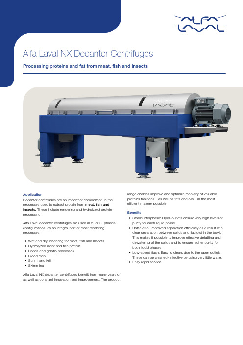
ApplicationDecanter centrifuges are an important component, in the processes used to extract protein from meat, fish and insects. These include rendering and hydrolyzed protein processing.Alfa Laval decanter centrifuges are used in 2- or 3- phases configurations, as an integral part of most rendering processes.•Wet and dry rendering for meat, fish and Insects •Hydrolyzed meat and fish protein•Bones and gelatin processes•Blood meal•Surimi and krill•SkimmingAlfa Laval NX decanter centrifuges benefit from many years of as well as constant innovation and improvement. The product range enables improve and optimize recovery of valuable proteins fractions – as well as fats and oils – in the most efficient manner possible.Benefits•Stable interphase: Open outlets ensure very high levels of purity for each liquid phase.•Baffle disc: Improved separation efficiency as a result of a clear separation between solids and liquid(s) in the bowl.This makes it possible to improve effective defatting and dewatering of the solids and to ensure higher purity for both liquid phases.•Low-speed flush: Easy to clean, due to the open outlets.These can be cleaned- effective by using very little water.•Easy rapid service.Working principleSeparation takes place in a horizontal, cylindrical bowlequipped with a screw conveyor. The feed is led into the bowl through a stationary inlet/feed tube [10] and smoothly accelerated by an inlet distributor [5] in – the feed zone.Centrifugal force causes sedimentation of the suspended solids inside the bowl [4].The conveyor [3] rotates in the same direction as the bowl,but at a different speed – called the differential speed. Thisdifference moves the solids to the conical end, where they are lifted out of the liquid level (pond) into a dry zone (beach). Here the capillary liquid is drained centrifugally, before being dis charged through the solids outlet [7] the casing.Separation takes place over the entire length of the cylindrical part of the bowl. The clarified liquid or liquids leave the bowlby flowing over an adjustable weir into the casing.1: Gearbox 2: Liquid outlet 3: Screw conveyor 4: Wall of the bowl 5: Inlet distributor 6: Conical end7: Cleaned slurry/muck outlet 8: Feed inlet9: Discharge ports 10: Feed tubeDesignNX decanter centrifuges are specially designed with a focus on performance, reliability, efficiency, easy access and quiet running. The cover is fitted with hinges to make access easy.The rotating assembly is mounted on a compact, welded box beam frame with main bearings at both ends. The motors are mounted in-line on the decanter itself to ensure the smallest possible footprint. The bowl is driven at the conical end by an electric motor with a V-belt transmission. NX decantercentrifuges are available in 2-phase or 3-phase configurations that are easy to adapt to the demands associated with a specific operating requirements. Each unit can also be adjusted on site.The centrifuge can be equipped with a CIP bar with nozzles/spray head to clean the bowl exterior and the casing/cover, as well as the inside of the bowl.Drive systemIn all Alfa Laval decanter centrifuges, the bowl is driven towards the conical end by an electric motor and V-belt transmission. Power is transferred to the conveyor via a planetary or Direct Drive gearbox.The speed difference is controlled in different ways, depending on the type of unit:•NX countershaft decanters feature a countershafttransmission, in which pulleys can be changed manually to regulate the input shaft speed of the gearbox, and thereby the differential speed•NX VFD-driven decanters are equipped with an automatic back drive system for the main motor.•The back drive motor is coupled to a Direct Drive (DD)gearbox that continuously adjusts the differential speed during operation.Direct Drive is a unique system developed and manufactured by Alfa Laval, to enable processing at maximum torque, thus resulting in best possible dryness of the solids.MaterialsThe bowl, conveyor, inlet tube, outlets, cover and other parts that are in direct contact with the process media are all made of stainless steel or duplex steel. The frame is made of mild steel with an epoxy enamel finish. The discharge ports,conveyor flights and feed zone are protected with materials that are highly resistant to abrasive solid particles.Solids transportDepending on the application, the inner surface of the bowl features either grooves or ribs. These ensures good solids conveying efficiency and limits how much the product slides along the inner surface on the bowl, which tends to generate abrasion, particularly if the solids are hard.Feed zoneThe feed zone is available with exchangeable wear liners made of tungsten carbide for additional wear protection.360° solids dischargesThe spokes are protected against wear by use of "saddles"made of tungsten carbide. The 360° solids discharge is extremely effective because there is no thing to hinder or restrict scrolling the cake out of the bowl.AutomationDecanter centrifuges equipped with variable frequency drives (VFD) are also available with control solutions to comply with your specific operating requirement. Whether you are looking for a control system that operates the decanter only or to more advanced control systems with additional functionality.Alfa Laval decanter automation can help you achieving your specific process performance goals by easy processadjustments, real-time status feedback, automated process adjustments and automated cleaning cycles.Additional featuresThe specially designed architecture of the bowl and conveyor in Alfa Laval decanter centrifuges makes it possible to effectively separate the solids and liquid phase(s) in order to maximize retention times. Keeping the input material in the bowl longer gives higher level of purity in the liquid’s phase(s) and greater dryness in the solid phase. The open outlets make it possible to maintain a stable interphase, even when the feed flows and composition vary by +/- 20%. A stable interface layer between oil and stick water is important for achieving the best possible separation efficiency in both liquid phases, even with emulsions. Open outlets also help ensure that the bowlcan be kept very clean, and make it easy to carry out visual inspections. This design also simplifiesthe decanter’s flush and CIP sequences. Array Protecting the flightsThe conveyor is protected by a coating that contains micro-grains of tungsten carbide, which aresprayed onto the upper 1/3 of the pushing face of the flights while hot. For particularly abrasiveapplications, the conveyor’s flights can be protected with tungsten carbide tiles and flame sprayedtungsten carbide. ArrayEasy to cleanDecanters fitted with an automation control system can execute a high-speed cleaning mode,followed by a low-speed cleaning mode by using frequency converters on the main and back drivemotors. Cleaning-in-place (CIP) media are introduced inside and outside the bowl. A spray bar(optional) on the cover effectively completes the cleaning by spraying water on the outside of thebowl external face. A CIP program featuring repeated sequences of high- and low-speed modesfor water, caustic and acid cleaning agents ensures supremely effective CIP cycle. The duration ofeach sequence, can be adjusted to your particular operating conditions ArrayLow-speed cleaning-in-placeThis is done by switching the direction in which the bowl rotates, at low speed. As the bowlperiodically changes rotation direction, a wave of liquid moves from one end to the other, cominginto contact with all the internal parts. At the same time, the turbulence resulting from this liquidmovement effectively cleans all the outlets and enhances the overall cleaning effect.The frame casing is a box beam profile, featuring an integral casing fitted with hinges. The casingand cover are made of AISI 316 stainless steel, with stainless steel cladding in the neutral bowl’scompartment. Due to their particularly smart design, Alfa Laval decanter centrifuges can beserviced very quickly. For example, it takes less than 3 hours to remove and replace a completerotating assembly.Connected servicesAlfa Laval decanter centrifuges that feature decanter automation can also be fitted with IoTconnectivity hardware that can provide you with full operating data, along with condition monitoringand process optimization. Please refer to the Alfa Laval website for more information.ServiceInvesting in an Alfa Laval decanter centrifuge solution is the first step towards a unique partnershipwith Alfa Laval Service. Our strong service presence in local market, combined with the capabilitiesof skilled Field Service Engineers, provides you and your operations with the support that you needto maximize processing uptime. A Service Agreement takes this one step further. Contact yourlocal Alfa Laval sales for more information.DimensionsDesignation NX912/913NX3650NX4450NX438NX5040NX5540NX6540NX7240 Length (L) (mm/inches)3,216/126.64,071/155.664,734/186.964,925/193.904,976/195.95,416/215.606,174/246.066,459/254.27 Width (W) (mm/ inches)780/30.7990/39.981,060/41.731,190/46.91,190/46.91,300/51.21,450/57.091,510/59.45 Height (H) (mm/inches)960/37.81,304/51.321,376/54.171,445/56.91,651/651,696/66.81,791/70.511,852/72.91 Gross weight (kg/lbs)1,500/3,3002,300/5,1003,200/7,1004,800/10,5824,900/10,8005,120/11,3006,500/14,3508,300/18,300Technical specificationsDesignation NX912/913NX3650NX4450NX438NX5040NX5540NX6540NX7240 Available angles in °10, 206, 10 or 206, 10 or 20106, 10 or 206, 10 or 206, 10 or 206, 10 or 20 Bowl diameter in mm/inches280/11.02360/14.17440/17.32480 / 18.89500/19.7550/21.65650/25.59720/28.35G-force, max. x g3,0303,5493,5513,5743,6223,5543,4913,384Total weight, net in kg/lbs1,500/3,3502,300/5,1003,200/7,1004,800/10,5824,900/10,8005,120/11,3006,500/14,3508,300/18,300 Sound pressure level1) dB(A) re. 20mPa81798185838383841) In compliance with EN ISO 4871 and EN 12547This document and its contents are subject to copyrights and other intellectual property rights owned by Alfa Laval Corporate AB. No part of this document may be copied, re-produced or transmitted in any form or by any means, or for any purpose, without Alfa Laval Corporate AB’s prior express written permission. Information and services provided in this document are madeas a benefit and service to the user, and no representations or warranties are made about the accuracy or suitability of this information and these services for any purpose. All rights arereserved.200005995-2-EN-GB© Alfa Laval Corporate AB How to contact Alfa LavalUp-to-date Alfa Laval contact details for all countries are always availableon our website at 。
离心机Allegra X 64R中文说明书
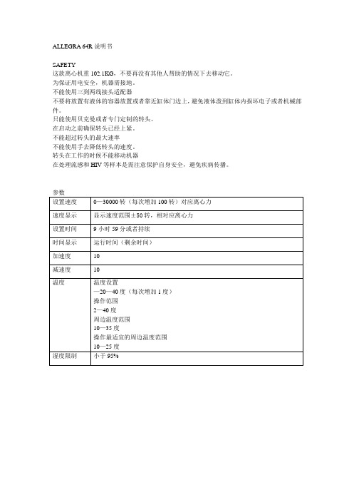
减速度
10
温度
温度设置
—20—40度(每次增加1度)
操作范围
2—40度
周边温度范围
10—35度
操作最适宜的周边温度范围
10—25度
湿度限制
小于95%
转头描述
最大转速
最大离心力
4°C最大转速
4°C最大离心力
最大容量
转头编号
F1202 45°定角转头
30000
644ห้องสมุดไป่ตู้0
28500
58120
12*2.0/1.5
开门
只有当开门的指示灯亮起的时候才能将门打开
瞬时
按下瞬时键时离心机以最大加速度开始运行;当松开瞬时键时,离心机以最大减速度减速至0.
空间要求
准备和安装:
为了尽快达到所需要的温度在运行前应根据需要加热或预冷转头。在20度及以上温度高转速运行之前要让离心机在10度运行5到10分钟,避免机器过热。
1.检查机身铭牌,确认离心机运行所需电压是否相符,确认之后讲插头插入插座。
输入运行参数:
选择转头编号:
转头编号印在转头上面,离心机内部保存有所有能够在该离心机上使用的转头型号清单和每个转头的详细参数,如果输入一个不允许的数值后按开始键,那么转头在开始旋转后不久屏幕上就会显示错误信息,运行会逐渐停止。
1.按rotor键,在速度的显示栏上会出现上一次使用的转头型号
2.按上火下键选择转头知道屏幕上显示的和要使用的相符。
F0630 30°定角转头
26,200
59,860
21,500
40,310
638.5
361231
GS-TB-014
F0650 25°定角转头
阿法拉伐离心机中文说明
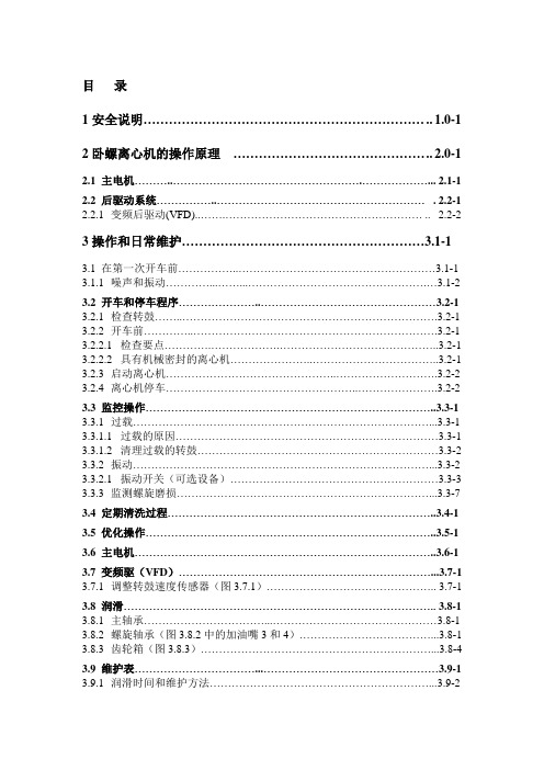
目录1安全说明………………………………………………………….. 1.0-1 2卧螺离心机的操作原理……………………………………….. 2.0-12.1 主电机………..…………………………………………….………………... 2.1-1 2.2后驱动系统……………..………………………………………………… . 2.2-1 2.2.1变频后驱动(VFD)..…….……………………………………………… .. 2.2-23操作和日常维护…………………………………………………3.1-1 3.1在第一次开车前……………..………………………………………………3.1-1 3.1.1噪声和振动…………...……...………………………………………….…3.1-2 3.2开车和停车程序…………………..…………………………………………3.2-1 3.2.1 检查转鼓……..…………………………………………………………….3.2-1 3.2.2开车前…………..………………………………………………………….3.2-1 3.2.2.1检查要点………….……………….……………………………………..3.2-1 3.2.2.2具有机械密封的离心机…………………..……………………………..3.2-1 3.2.3启动离心机………………………………………..……………………….3.2-2 3.2.4离心机停车……………………………………………..………………….3.2-2 3.3监控操作……………………………………………………………………..3.3-1 3.3.1过载………………………………………………………………………...3.3-1 3.3.1.1过载的原因………………………………………………………………3.3-1 3.3.1.2清理过载的转鼓…………………………………………………………3.3-2 3.3.2振动………………………………………………………………………...3.3-2 3.3.2.1振动开关(可选设备)…………………………………………………3.3-3 3.3.3监测螺旋磨损……………………………………………………………...3.3-73.4定期清洗过程………………………………………………………………..3.4-1 3.5优化操作……………………………………………………………………..3.5-1 3.6主电机………………………………………………………………………..3.6-1 3.7变频驱(VFD)……………………………………………………………...3.7-1 3.7.1调整转鼓速度传感器(图3.7.1)……………………………………….. 3.7-1 3.8润滑………………………………………………………………………….. 3.8-1 3.8.1主轴承……………………………...………………………………………3.8-1 3.8.2螺旋轴承(图3.8.2中的加油嘴3和4)………………………………...3.8-1 3.8.3齿轮箱(图3.8.3)………………………………………………………...3.8-4 3.9维护表……………………………...…………………………………………3.9-1 3.9.1润滑时间和维护方法……………………………………………………...3.9-2表3.9.1润滑表………………………………………………………….…3.9-2 表3.9.1.1维护周期…………………………………………………………3.9-3 3.9.2润滑剂型号………………………………………………………………...3.9-4表3.9.2润滑剂、润滑工具表…………………………………………… 3.9-44拆卸和组装……………………………………………………… 4.0-0 4.1旋转组件……………………………………………………………………...4.1-1 4.1.1拆卸转鼓(图4.1.1和4.1.2)…………………………………………….4.1-1 4.1.2安装转鼓(图4.1.1和4.1.2)…………………………………………….4.1-5 4.1.3拆卸大端轴颈(图4.1.4)………………………………………………...4.1-7 4.1.4安装大端轴颈(图4.1.4)………………………………………………...4.1-7 4.1.5拆卸小端轴颈(图4.1.5)………………………………………………...4.1-9 4.1.6安装小端轴颈(图4.1.5)……………………………………………….4.1-10 4.1.7拆卸齿轮箱(图4.1.6和4.1.8)………………………………………….4.1-11 4.1.8安装齿轮箱(图4.1.7和4.1.8)…………………………………………4.1-13 4.1.9装配新的排污口衬套…………………….………………………………4.1-144.2主轴承…………….…………………………………………………………..4.2-1 4.2.1拆卸大端主轴承(图4.2.1)…………………………………….…………..4.2-1 4.2.2组装大端主轴承(图4.2.1)………………………………………………...4.2-3 4.2.3拆卸小端主轴承(图4.2.4)………………………………………………...4.2-7 4.2.4安装小端主轴承(图4.2.4)………………………………………………...4.2-9 4.3螺旋轴承……………………………………………………….…….……….4.3-1 4.3.1拆卸螺旋大端轴承(图4.3.1)…………………………………….………..4.3-1 4.3.2组装螺旋轴承大端轴承(图4.3.1)………………………………………4.3-3 4.3.3拆卸螺旋轴承小端轴承(图4.3.4)……………………………………...4.3-7 4.3.4安装螺旋轴承小端轴承(图4.3.4)……………………………………...4.3-84.4螺旋…………………………………………………………………………...4.4-1 4.4.1从转鼓中拆卸螺旋(图4.4.1)……………………………………………4.4-1 4.4.2将螺旋装入转鼓(图4.4.1)………………………………………………...4.4-2 4.5主电机……………………………………………………………………….. 4.5-1 4.5.1拆卸主电机(图4.5.1)……………………………………………….…..4.5-1 4.5.2组装主电机(图4.5.1,4.5.2和4.5.3)………………………………….…..4.5-5 4.5.3调紧V形皮带,皮带张力表………………………………………………4.5-74.6变频后驱动装置(VFD)…………………….……………………………..4.6-1 4.6.1拆卸变频驱动器(图4.6.1)………….………………………………….4.6-14.6.2组装变频驱动器(图4.6.1)……………………………………………..4.6-1 5补充文档…………………………………………………………5.0-01安全说明请务必严格按照以下要求进行操作,否则会给您造成人员以及财产的损失。
3#脱水机操作手册(阿法拉伐)1

3#脱水机试行操作手册(阿法拉伐脱水机)目录1、检查2、开停阿法拉伐离心脱水机3、启动离心机的具体步骤4、关闭离心机的具体步骤5、清洗6、维护及保养7、安全及注意事项1检查1.1清洗水检查1.1.1检查连接管道是否正常。
1.1.2检查清洗水泵是否正常(主要有地脚螺钉、盘根、联轴器、润滑部分等)1.1.3检查电磁阀、压力是否正常。
1.1.4打开阀门及相应的开关。
1.2污泥投加部分检查1.2.1检查连接管道是否正常。
1.2.2检查阀门、污泥流量计、切削泵、污泥投加泵是否正常。
1.2.3打开阀门及相应的开关。
1.3絮凝剂投加部分检查1.3.1检查连接管道是否正常。
1.3.2检查阀门、絮凝剂流量计、絮凝剂投加泵是否正常。
1.3.3打开阀门及相应的开关。
1.4输送部分检查检查皮带输送机、输送带、支架、托滚是否正常。
1.5阿法拉伐离心脱水机检查(每天、每月、每半年)1.5.1每天的检查(22项)* 检查机器周围的清洁状况--察看是否有润滑油、润滑脂和其它液体泄漏的痕迹。
* 检查机器的振动状况。
* 检查轴承和机器总体的噪音状况。
* 检查机器表露的螺栓和螺母是否有松动。
如有则紧固。
* 检查润滑油的流量和油箱的液位。
* 检查润滑油的压力。
* 检查润滑油的温度。
* 检查整个润滑系统的工作是否正常,有否泄漏。
* 察看齿轮箱是否有漏油现象。
* 检查主电机的电流。
* 检查主电机的温度。
* 检查减振部件的总体状况。
* 检查柔性连接有否泄漏和老化现象。
* 检查进料量。
* 检查螺旋的扭矩。
* 检查背驱电机的温度。
* 停机前进水冲洗直到转鼓内干净,确保机内不积留料液和渣。
* 检查连接管道是否正常。
* 检查紧固螺栓是否松动。
* 检查转鼓、电机、支撑机架是否出现裂缝、凹痕、孔隙或沟槽。
* 检查各个润滑部分是否正常。
* 检查罩壳是否盖紧。
1.5.2 每月的检查和维护* 检查进料管,清除可能有的料渣。
1.5.3 半年一次的检查和维护(8项)* 检查皮带张紧力。
离心机使用操作说明
离心机使用操作说明
选择转头编号:
转头编号印在转头上面,离心机内部保存有所有能够在该离心机上使用的转头型号清单和每个转头的详细参数,如果输入一个不允许的数值后按开始键,那么转头在开始旋转后不久屏幕上就会显示错误信息,运行会逐渐停止。
1、使用前做好登记并贴使用标识牌;
2、离心前一定要用平衡离心管(重量平衡),盖上样品盖子并旋紧;
3、把平衡好的离心管对称放入离心陀中(位置平衡),盖上离心陀子的盖子,注意必须拧紧;
4、打开电源,将离心速度调至需要刻度,启动离心机;
5、完成离心时,要等待离心机自动停止,不允许用手或其他物件迫使离心机停转,待转头停止后,才能打开舱门;
6、尽快取出离心管,先观察离心管是否完全,以及沉淀的维修,尽速把上清倒出,小心不要把沉淀弄浑浊;
7、使用完毕应卸下转头,用布擦拭离心机内表面,以免水汽凝结,腐蚀仪器;
8、本仪器必须放置于水平而且稳定的平台上,不能置于阳光的直接照射下,并确保离心机;
9、四周有足够的空间保证空气流通;
10、请勿于易燃易爆环境使用本仪器,而且不能用于离心具爆炸性或剧烈反应的物质;
11、请勿在转子尚未可靠上紧之前开始操作,运行期间不要搬动或敲击离心机;
12、请避免使用高浓度碱、酸,氯化物,高浓度盐水以及包含铜、汞等重金属离子的腐蚀性;
13、溶液,假如转子或仪器内腔粘上以上溶液,请立即使用中性清洁液清理。
阿法拉伐中文说明书1
目录1安全说明………………………………………………………….. 1.0-1 2卧螺离心机的操作原理……………………………………….. 2.0-12.1 主电机………..…………………………………………….………………... 2.1-1 2.2后驱动系统……………..………………………………………………… . 2.2-1 2.2.1变频后驱动(VFD)..…….……………………………………………… .. 2.2-23操作和日常维护…………………………………………………3.1-1 3.1在第一次开车前……………..………………………………………………3.1-1 3.1.1噪声和振动…………...……...………………………………………….…3.1-2 3.2开车和停车程序…………………..…………………………………………3.2-1 3.2.1 检查转鼓……..…………………………………………………………….3.2-1 3.2.2开车前…………..………………………………………………………….3.2-1 3.2.2.1检查要点………….……………….……………………………………..3.2-1 3.2.2.2具有机械密封的离心机…………………..……………………………..3.2-1 3.2.3启动离心机………………………………………..……………………….3.2-2 3.2.4离心机停车……………………………………………..………………….3.2-2 3.3监控操作……………………………………………………………………..3.3-1 3.3.1过载………………………………………………………………………...3.3-1 3.3.1.1过载的原因………………………………………………………………3.3-1 3.3.1.2清理过载的转鼓…………………………………………………………3.3-2 3.3.2振动………………………………………………………………………...3.3-2 3.3.2.1振动开关(可选设备)…………………………………………………3.3-3 3.3.3监测螺旋磨损……………………………………………………………...3.3-73.4定期清洗过程………………………………………………………………..3.4-1 3.5优化操作……………………………………………………………………..3.5-1 3.6主电机………………………………………………………………………..3.6-1 3.7变频驱(VFD)……………………………………………………………...3.7-1 3.7.1调整转鼓速度传感器(图3.7.1)……………………………………….. 3.7-1 3.8润滑………………………………………………………………………….. 3.8-1 3.8.1主轴承……………………………...………………………………………3.8-1 3.8.2螺旋轴承(图3.8.2中的加油嘴3和4)………………………………...3.8-1 3.8.3齿轮箱(图3.8.3)………………………………………………………...3.8-4 3.9维护表……………………………...…………………………………………3.9-1 3.9.1润滑时间和维护方法……………………………………………………...3.9-2表3.9.1润滑表………………………………………………………….…3.9-2 表3.9.1.1维护周期…………………………………………………………3.9-3 3.9.2润滑剂型号………………………………………………………………...3.9-4表3.9.2润滑剂、润滑工具表…………………………………………… 3.9-44拆卸和组装……………………………………………………… 4.0-0 4.1旋转组件……………………………………………………………………...4.1-1 4.1.1拆卸转鼓(图4.1.1和4.1.2)…………………………………………….4.1-1 4.1.2安装转鼓(图4.1.1和4.1.2)…………………………………………….4.1-5 4.1.3拆卸大端轴颈(图4.1.4)………………………………………………...4.1-7 4.1.4安装大端轴颈(图4.1.4)………………………………………………...4.1-7 4.1.5拆卸小端轴颈(图4.1.5)………………………………………………...4.1-9 4.1.6安装小端轴颈(图4.1.5)……………………………………………….4.1-10 4.1.7拆卸齿轮箱(图4.1.6和4.1.8)………………………………………….4.1-11 4.1.8安装齿轮箱(图4.1.7和4.1.8)…………………………………………4.1-13 4.1.9装配新的排污口衬套…………………….………………………………4.1-144.2主轴承…………….…………………………………………………………..4.2-1 4.2.1拆卸大端主轴承(图4.2.1)…………………………………….…………..4.2-1 4.2.2组装大端主轴承(图4.2.1)………………………………………………...4.2-3 4.2.3拆卸小端主轴承(图4.2.4)………………………………………………...4.2-7 4.2.4安装小端主轴承(图4.2.4)………………………………………………...4.2-9 4.3螺旋轴承……………………………………………………….…….……….4.3-1 4.3.1拆卸螺旋大端轴承(图4.3.1)…………………………………….………..4.3-1 4.3.2组装螺旋轴承大端轴承(图4.3.1)………………………………………4.3-3 4.3.3拆卸螺旋轴承小端轴承(图4.3.4)……………………………………...4.3-7 4.3.4安装螺旋轴承小端轴承(图4.3.4)……………………………………...4.3-84.4螺旋…………………………………………………………………………...4.4-1 4.4.1从转鼓中拆卸螺旋(图4.4.1)……………………………………………4.4-1 4.4.2将螺旋装入转鼓(图4.4.1)………………………………………………...4.4-2 4.5主电机……………………………………………………………………….. 4.5-1 4.5.1拆卸主电机(图4.5.1)……………………………………………….…..4.5-1 4.5.2组装主电机(图4.5.1,4.5.2和4.5.3)………………………………….…..4.5-5 4.5.3调紧V形皮带,皮带张力表………………………………………………4.5-74.6变频后驱动装置(VFD)…………………….……………………………..4.6-1 4.6.1拆卸变频驱动器(图4.6.1)………….………………………………….4.6-14.6.2组装变频驱动器(图4.6.1)……………………………………………..4.6-1 5补充文档…………………………………………………………5.0-01安全说明请务必严格按照以下要求进行操作,否则会给您造成人员以及财产的损失。
10立方米离心机技术 阿法拉法
-
5
ALDEC30 离心脱水机设备技术协议
七、离心脱水机主要制造和检测标准
表 7-1 离心脱水机主要制造和检测标准
序号
项
目
标
准
EN ISO 9001:1994,ISO9001:1994
1
生产质量管理标准
DS ISO 9001:1994,批核证书号 910108
2
转鼓离心铸造标准 DIN500493.1.B
98-99%; 10m3/h;
4) pH 值
6~9。
7、用户对出泥的要求:
1) 脱水后的污泥含水率 <75%;
2) 固体回收率
≥95%;
3) 药量消耗
<5 kg/tds。
-
1
三、 供货范围
序号 项目
1
离心 脱水机
2
综合启动 控制柜
ALD安装供货范围:
型号
规格
单位 数量
丁氰密封
1年
整机使用寿命承诺 20 年。
-
6
ALDEC30 离心脱水机设备技术协议
九、辅助设备技术描述: 9.1 离心机电控柜技术描述:一台
每台离心脱水机配置一台电控柜,该电控柜为离心脱水机、泥水分离器、加药泵、 污泥进料泵等设备提供电源、控制、显示报警,以确保污泥脱水系统的安全运行。絮凝 剂配制系统的报警应在离心机控制柜上显示,以确保絮凝剂制备投加系统的安全运行。
6. 端子 国际标准: IEC185/IEC51/73 其它电气及机械性能满足招标文件的指标
7. 控制继电器 国际标准: IEC65/IEC435 其它电气及机械性能满足招标文件的指标
8. 按钮及指示 国际标准: IEC947-5-1/IEC536/IEC529 其它电气及机械性能满足招标文件的指标
阿法拉伐 Alfa Laval
•Operating water pressure
too low •Seal ring defective
check the water pressure
2.0 – 6.0 bar. check the seal ring for operating slide
95
Safety Instruction
41
Gravity disc too big
42
Gravity disc too small
43
44
45
46
47
48
49
50
51
Before Start
• Make sure that the separator is mounted correctly.
•All connections are tightened.
一个连续的液相和一个或两个分散相。
• 多相体一定要有不同的比重,否则,由沉淀作用产生的分离将 是不可能的。固相的比重肯定是最大。 • 工作液体中固相物质的浓度不应超过25%(体积)。 • 被分离出的固体颗粒或小液滴大小应在0.1~500uM之间。
21
分离的效果可以用沉降速率来反映
Stokes´ 定律
3
一 阿法拉伐(Alfa Laval)简介
• Alfa Laval是一家位于瑞典的跨国公司
• Alfa Laval是离心机的发明者,最大的制造商 • Alfa Laval有多种产品,换热器,离心机,
泵,阀,技术,服务... • Alfa Laval涉及领域广。石油,化工,制 药,油脂,食品,环保,船舶,电厂… • Alfa Laval在中国有代表处。上海,北京, 广州...
c) too low back pressure
- 1、下载文档前请自行甄别文档内容的完整性,平台不提供额外的编辑、内容补充、找答案等附加服务。
- 2、"仅部分预览"的文档,不可在线预览部分如存在完整性等问题,可反馈申请退款(可完整预览的文档不适用该条件!)。
- 3、如文档侵犯您的权益,请联系客服反馈,我们会尽快为您处理(人工客服工作时间:9:00-18:30)。
目录1安全说明…………………………………………………………1.0-1 2卧螺离心机的操作原理………………………………………2.0-12.1 主电机………..…………………………………………….………………2.1-12.2后驱动系统……………..…………………………………………………2.2-12.2.1变频后驱动(VFD)..…….……………………………………………… 2.2-2 3操作和日常维护…………………………………………………3.1-13.1在第一次开车前……………..………………………………………………3.1-13.1.1噪声和振动…………...……...………………………………………….…3.1-23.2开车和停车程序…………………..…………………………………………3.2-13.2.1 检查转鼓……..…………………………………………………………….3.2-13.2.2开车前…………..………………………………………………………….3.2-13.2.2.1............................................................... 检查要点………….……………….……………………………………..3.2-13.2.2.2.................................................. 具有机械密封的离心机…………………..……………………………..3.2-13.2.3启动离心机………………………………………..……………………….3.2-23.2.4离心机停车……………………………………………..………………….3.2-23.3监控操作……………………………………………………………………..3.3-13.3.1过载………………………………………………………………………...3.3-13.3.1.1............................................................. 过载的原因………………………………………………………………3.3-13.3.1.2........................................................ 清理过载的转鼓…………………………………………………………3.3-23.3.2振动………………………………………………………………………...3.3-2 .....3.3.2.1振动开关(可选设备)…………………………………………………3.3-3 3.3.3监测螺旋磨损……………………………………………………………...3.3-73.4定期清洗过程………………………………………………………………..3.4-13.5优化操作……………………………………………………………………..3.5-13.6主电机………………………………………………………………………..3.6-13.7变频驱(VFD)……………………………………………………………...3.7-1 3.7.1调整转鼓速度传感器(图3.7.1)……………………………………….. 3.7-13.8润滑…………………………………………………………………………..3.8-13.8.1主轴承……………………………...………………………………………3.8-13.8.2螺旋轴承(图3.8.2中的加油嘴3和4)………………………………...3.8-13.8.3齿轮箱(图3.8.3)………………………………………………………...3.8-43.9维护表……………………………...…………………………………………3.9-13.9.1润滑时间和维护方法……………………………………………………...3.9-2表 3.9.1润滑表………………………………………………………….…3.9-2表 3.9.1.1维护周期…………………………………………………………3.9-33.9.2润滑剂型号………………………………………………………………...3.9-4 表3.9.2润滑剂、润滑工具表……………………………………………3.9-44拆卸和组装………………………………………………………4.0-04.1旋转组件……………………………………………………………………...4.1-14.1.1拆卸转鼓(图4.1.1和4.1.2)…………………………………………….4.1-14.1.2安装转鼓(图4.1.1和4.1.2)…………………………………………….4.1-54.1.3拆卸大端轴颈(图4.1.4)………………………………………………...4.1-74.1.4安装大端轴颈(图4.1.4)………………………………………………...4.1-74.1.5拆卸小端轴颈(图4.1.5)………………………………………………...4.1-94.1.6安装小端轴颈(图4.1.5)……………………………………………….4.1-104.1.7拆卸齿轮箱(图4.1.6和4.1.8)………………………………………….4.1-114.1.8安装齿轮箱(图4.1.7和4.1.8)…………………………………………4.1-134.1.9装配新的排污口衬套…………………….………………………………4.1-144.2主轴承…………….…………………………………………………………..4.2-1 4.2.1拆卸大端主轴承(图4.2.1)…………………………………….…………..4.2-14.2.2组装大端主轴承(图4.2.1)………………………………………………...4.2-34.2.3拆卸小端主轴承(图4.2.4)………………………………………………...4.2-74.2.4安装小端主轴承(图4.2.4)………………………………………………...4.2-94.3螺旋轴承……………………………………………………….…….……….4.3-14.3.1拆卸螺旋大端轴承(图4.3.1)…………………………………….………..4.3-14.3.2组装螺旋轴承大端轴承(图4.3.1)………………………………………4.3-34.3.3拆卸螺旋轴承小端轴承(图4.3.4)……………………………………...4.3-74.3.4安装螺旋轴承小端轴承(图4.3.4)……………………………………...4.3-84.4螺旋…………………………………………………………………………...4.4-1 4.4.1从转鼓中拆卸螺旋(图4.4.1)……………………………………………4.4-14.4.2将螺旋装入转鼓(图4.4.1)………………………………………………...4.4-24.5主电机……………………………………………………………………….. 4.5-14.5.1拆卸主电机(图4.5.1)……………………………………………….…..4.5-14.5.2组装主电机(图4.5.1,4.5.2和4.5.3)………………………………….…..4.5-54.5.3调紧V形皮带,皮带力表………………………………………………4.5-74.6变频后驱动装置(VFD)…………………….……………………………..4.6-1 4.6.1拆卸变频驱动器(图4.6.1)………….………………………………….4.6-14.6.2组装变频驱动器(图4.6.1)……………………………………………..4.6-15补充文档…………………………………………………………5.0-01安全说明请务必严格按照以下要求进行操作,否则会给您造成人员以及财产的损失。
卧螺离心机安全注意事项1.未得到Alfa Laval公司的预先书面认可,卧螺离心机不得用于分离易燃、有毒、以及具有腐蚀性、放射性的物质。
2.在准备安装或是操作卧螺离心机之前,请详细阅读此安全指南手册以及操作手册,并且遵守其中的所有要求。
3.不要操作警告标识已损坏或是没有警告标识的离心机。
4.如果机器振动幅度超过24毫米/秒(美国标准:1英寸/秒),请立即停车!5.当进料温度超过安装、操作以及维修三本手册数据清单中注明的限度时,不许使用离心机。
6.转鼓中有冰水、结冻或是有坚硬的物质时,不能启动离心机。
7.不要在超过手册数据清单中所规定的,或是离心机铭牌上标示的转鼓最大转速以及固体最大密度下运行离心机。
8.在没有皮带护罩以及其他保护设施时,请不要操作离心机。
9.定期检查所有自动切断装置以及监测系统,以确保其正常运行。
1.0-110、未能确定离心机是否完全停止、主电源是否完全断开以及主开关是否被断开并安全锁定的情况下,请不要试图拆卸离心机。
11、当离心机的转鼓、电机或是支承机架出现裂缝、凹痕、孔隙或者沟槽时,请不要操作离心机。
12、不要使用未经Alfa Laval公司推荐的工具去拆卸或是安装离心机。
13、本离心机不能用于超出购买设备时与Alfa Laval公司签订的应用或是处理原料的围。
14、遵照设备的所有润滑程序以及步骤。
15、至少每年定期检查一次离心机和电机的机座以及所有支承机架、机壳和联接管件。
16、旋转部件附近不得放置抹布以及松散的衣物。
17、当拆卸、安装或操作、运行以及维修机器时,请严格遵循Alfa Laval公司要求的步骤。
未经Alfa Laval公司同意,请不要擅自改变操作步骤。
18、只有经过专门培训的技术人员才能够操作、清洁、拆卸以及安装卧螺离心机。
19、在离心机没有完全安装完毕的情况下,不得启动机器。
20、当电机的运转方向与指示箭头的方向相反时,请不要对离心机进行任何操作。
1.0-221、如果离心机配有变频装置,则应确保其最高频率不会导致离心机超速运转。
并且,应该提供至少两套可以独立工作的分离保护装置。
见安装数据手册6.9节。
22、在离心机达到全速运转前,不能进料或者进水。
23、当离心机需要对高温或是腐蚀性的液体进行操作时,请确保液体意外的溅出不会伤害到离心机下面的工作人员。
24、当离心机停车时,不要让大量温度过高的或是腐蚀性的液体由进料管进入机体,因为它们可能会伤害在离心机下面的工作人员。
25、在卸料阀、卸料泵、传送液相或固相的输送器未打开之前,不允许启动进料泵或是冲洗离心机。
26、当操作有铰链罩壳的离心机时,须时刻注意检查罩壳是否由于人为疏忽或者机器运转的缘故而没有盖紧,若罩壳没有盖紧可能会引起事故。
27、当离心机高速运转时,请勿接触固相排出口,以防止被机器甩出的大块固体物质弄伤。
28、当用皮带起吊整台离心机或是离心机的部件时,比如:转鼓等部件,必须确吊件不会滑落。