bellimo-CCV
Belimo EV..F+BAC 电子调节阀数据表说明书
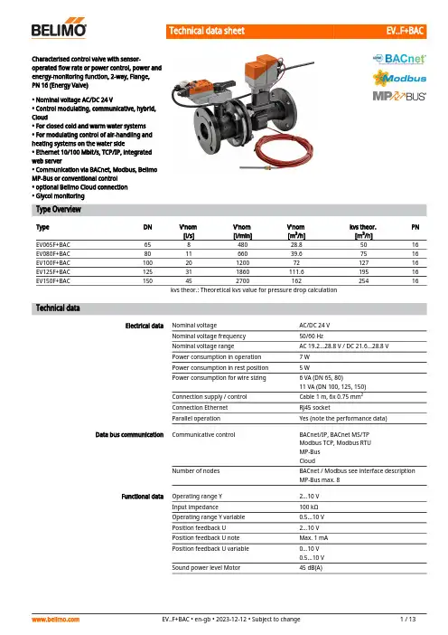
EV..F+BACCharacterised control valve with sensor-operated flow rate or power control, power andenergy-monitoring function, 2-way, Flange, PN 16 (Energy Valve)• Nominal voltage AC/DC 24 V• Control modulating, communicative, hybrid, Cloud• For closed cold and warm water systems • For modulating control of air-handling and heating systems on the water side• Ethernet 10/100 Mbit/s, TCP/IP, integrated web server• Communication via BACnet, Modbus, Belimo MP-Bus or conventional control • optional Belimo Cloud connection • Glycol monitoringType OverviewType DN V'nom [l/s]V'nom [l/min]V'nom [m³/h]kvs theor. [m³/h]PN EV065F+BAC 65848028.85016EV080F+BAC 801166039.67516EV100F+BAC 1002012007212716EV125F+BAC 125311860111.619516EV150F+BAC15045270016225416kvs theor.: Theoretical kvs value for pressure drop calculationTechnical dataElectrical dataNominal voltageAC/DC 24 V Nominal voltage frequency 50/60 HzNominal voltage rangeAC 19.2...28.8 V / DC 21.6...28.8 V Power consumption in operation 7 W Power consumption in rest position 5 WPower consumption for wire sizing 6 VA (DN 65, 80)11 VA (DN 100, 125, 150)Connection supply / control Cable 1 m, 6x 0.75 mm²Connection Ethernet RJ45 socketParallel operationYes (note the performance data)Data bus communicationCommunicative controlBACnet/IP, BACnet MS/TP Modbus TCP, Modbus RTU MP-Bus CloudNumber of nodesBACnet / Modbus see interface description MP-Bus max. 8Functional data Operating range Y 2...10 V Input impedance100 kΩOperating range Y variable 0.5...10 V Position feedback U 2...10 V Position feedback U note Max. 1 mA Position feedback U variable 0...10 V 0.5...10 V Sound power level Motor45 dB(A)EV..F+BACFunctional data V'max adjustable30...100% of V'nomControl accuracy±5% (of 25...100% V'nom) @ 20°C / Glycol 0%vol.Control accuracy note±10% (of 25...100% V'nom) @ -10...120°C /Glycol 0...50% vol.Min. controllable flow1% of V'nomParametrisation via integrated web server / ZTH EUFluid Cold and warm water, water with glycol up tomax. 50% vol.Fluid temperature-10...120°C [14...248°F]Close-off pressure ∆ps690 kPaDifferential pressure Δpmax340kPaFlow characteristic equal percentage, optimised in the openingrange (switchable to linear)Leakage rate air-bubble tight, leakage rate A (EN 12266-1)Pipe connection Flangeaccording to EN 1092-2Installation orientation upright to horizontal (in relation to the stem)Servicing maintenance-freeManual override with push-button, can be locked Temperature measurement Measuring accuracy absolute temperature± 0.35°C @ 10°C (Pt1000 EN60751 Class B)± 0.6°C @ 60°C (Pt1000 EN60751 Class B)Measuring accuracy temperature difference±0.18 K @ ΔT = 10 K±0.23 K @ ΔT = 20 KResolution0.05°CFlow measurement Measuring principle Ultrasonic volumetric flow measurementMeasuring accuracy flow±2% (of 25...100% V'nom) @ 20°C / glycol 0%vol.Measuring accuracy flow note±6% (of 25...100% V'nom) @ -10...120°C /glycol 0...50% vol.Min. flow measurement0.5% of V'nomGlycol monitoring Measurement display glycol0...40% or >40%Measuring accuracy glycolmonitoring±4% (0...40%)Safety data Protection class IEC/EN III, Protective Extra-Low Voltage (PELV)Degree of protection IEC/EN IP40IP54 when using protective cap or protectivegrommet for RJ45 socketPressure equipment directive CE according to 2014/68/EUEMC CE according to 2014/30/EUType of action Type 1Rated impulse voltage supply / control0.8 kVPollution degree3Ambient humidity Max. 95% RH, non-condensingAmbient temperature-30...50°C [-22...122°F]Storage temperature-40...80°C [-40...176°F]Materials Valve body EN-GJL-250 (GG 25)Flow measuring pipe EN-GJL-250 (GG 25), with protective paintClosing element Stainless steel AISI 316EV..F+BACMaterialsSpindle Stainless steel AISI 304Spindle seal EPDMSeatPTFE, O-ring Viton Immersion sleeveStainless steel AISI 316Technical data••••Safety notesThis device has been designed for use in stationary heating, ventilation and air-conditioning systems and must not be used outside the specified field of application, especially in aircraft or in any other airborne means of transport.Outdoor application: only possible in case that no (sea) water, snow, ice, insolation or aggressive gases interfere directly with the device and that it is ensured that the ambient conditions remain within the thresholds according to the data sheet at any time.Only authorised specialists may carry out installation. All applicable legal or institutional installation regulations must be complied with during installation.The device contains electrical and electronic components and must not be disposed of as household refuse. All locally valid regulations and requirements must be observed.Product featuresOperating modeThe HVAC performance device is comprised of four components: characterised control valve (CCV), measuring pipe with flow sensor, temperature sensors and the actuator itself. The adjusted maximum flow (V'max) is assigned to the maximum control signal DDC (typically 10 V / 100%). Alternatively, the control signal DDC can be assigned to the valve opening angle or to the power required on the heat exchanger (see power control). The HVAC performance device can be controlled via communicative or analogue signals. The fluid is detected by the sensor in the measuring pipe and is applied as the flow value. The measured value is balanced with the setpoint. The actuator corrects the deviation by changing the valve position. The angle of rotation α varies according to the differential pressure through the control element (see flow curves).Flow rate curvesTransmission behaviour HE Heat exchanger transmission behaviourDepending on the construction, temperature spread, fluid characteristics and hydronic circuit,the power Q is not proportional to the water volumetric flow V' (Curve 1). With the classicaltype of temperature control, an attempt is made to maintain the control signal Y proportionalto the power Q (Curve 2). This is achieved by means of an equal-percentage flow characteristic(Curve 3).Power control Alternatively, the control signal DDC can be assigned to the output power required at the heat exchanger.Depending on the water temperature and air conditions, the Energy Valve ensures theamount of water V' required to achieve the desired power.Maximum controllable power on heat exchanger in power control mode:Control characteristics The specially configured control parameters in connection with the precise velocity sensorensure a stable quality of control. They are, however, not suitable for rapid control processes,i.e. for domestic water control.Power controlQ'nom is the maximum possible power output on the heat exchanger.Q'max is the maximum power output on the heat exchanger which has been set with thehighest control signal DDC. Q'max can be set between 1% and 100% of Q'nom.Q'min 0% (non-variable).Flow controlV'nom is the maximum possible flow.V'max is the maximum flow rate which has been set with the highest control signal. V'max canbe set between 30% and 100% of V'nom.Creep flow suppression Given the very low flow speed in the opening point, this can no longer be measured by the sensor within the required tolerance. This range is overridden electronically.Opening valveThe valve remains closed until the flow required by the control signal DDC corresponds to 1%of V'nom. The control along the flow characteristic is active after this value has beenexceeded.Closing valveThe control along the flow characteristic is active up to the required flow rate of 1% of V'nom.Once the level falls below this value, the flow rate is maintained at 1% of V'nom. If the levelfalls below the flow rate of 0.5% of V'nom required by the control signal DDC, then the valvewill close.Configurable actuators The factory settings cover the most common applications. Single parameters can be modified with the Belimo service tools MFT-P or ZTH EU.CommunicationThe parametrisation can be carried out through the integrated web server (RJ45 connection to the web browser) or by communicative means.Additional information regarding the integrated web server can be found in the separate documentation."Peer to Peer" connectionhttp://belimo.local:8080The Notebook must be set to "DHCP".Make sure that only one network connectionis active.Standard IP address:http://192.168.0.10:8080Static IP addressPassword (read-only):User name: «guest»Password: «guest»Control signal inversionThis can be inverted in cases of control with an analogue control signal DDC. The inversion causes the reversal of the standard behaviour, i.e. at a control signal DDC of 0%, regulation is to V'max or Q'max, and the valve is closed at a control signal DDC of 100%.Hydronic balancingVia the integrated web server, the maximum flow rate (equivalent to 100% requirement) can be adjusted on the device itself, simply and reliably, in a few steps. If the device is integrated in the management system, then the balancing can be handled directly by the management system.Delta-T managerIf a heating or cooling register is operated with a differential temperature that is too low and thus with a flow rate that is too high, this will not result in an increased power output.Nevertheless, heating or cooling machines must provide the energy at a lower degree of efficiency. This means, that pumps circulate too much water and increase energy consumption unnecessarily.With the aid of the Energy Valve, it is simple to discover that operation is being carried out at a differential temperature that is too low, resulting in the inefficient use of energy.Necessary setting adjustments can now be carried out quickly and easily at any time. The integrated differential temperature limiting offers the user the possibility of defining a low limit value. The Energy Valve limits the flow rate automatically to prevent the level from falling below this value.The settings of the Delta-T manager can be made either directly on the web server or via the Belimo Cloud a direct analysis of the Delta-T behavior is carried out by Belimo experts.Power output of the heating or coolingregisters 1Diff. temperature between supply and return2Loss zone (heating or cooling registersaturation) 3Adjustable minimum differential temperature4Combination analogue - communicative(hybrid mode)With conventional control by means of an analogue control signal DDC, the integrated web server, BACnet, Modbus or MP-Bus can be used for the communicative position feedback.EV..F+BACPower and energy monitoring functionThe HVAC performance device is equipped with two temperature sensors. One sensor (T2) is integrated in the measuring pipe, the second sensor (T1) is included with the system,prewired, and must be installed in the water circuit on site. The sensors are used to record the fluid temperature of the supply and return lines of the consumer (heating/cooling coil). As the water quantity is also known, thanks to the flow measurement integrated in the system, the power released from the consumer can be calculated. Furthermore, the heating/cooling energy is also determined automatically by means of the evaluation of the power over time.The current data, e.g. temperatures, volumetric flow volumes, exchanger energyconsumption etc. can be recorded and accessed at any time by means of web browsers or communication.Data recordingThe recorded data (integrated data recording for 13 months) can be used for the optimisation of the overall system and for the determination of the performance of the consumer (heating/cooling coil).Download csv files through web browser.Belimo CloudAdditional services are available if the Energy Valve is connected to the Belimo Cloud: forinstance, several devices may be managed via Internet. Also, Belimo experts may help analyse the delta-T behaviour or provide written reports about the Energy Valve performance. Under certain conditions, the product warranty according to the applicable Terms and Conditions of Sale may be prolonged. The "Terms of Use for Belimo Cloud Services" in their currently valid version apply to the use of Belimo Cloud services. Further details may be found under [/ext-warranty]Glycol monitoring Glycol monitoring measures the actual glycol content, which is necessary for safe operation and optimised heat exchange.Manual override Manual override with push-button possible (the gear train is disengaged for as long as the button is pressed or remains locked).High functional safetyThe actuator is overload protected, requires no limit switches and automatically stops when the end stop is reached.Product featuresAccessoriesElectrical accessoriesDescriptionType Grommet for RJ connection module, Multipack 50 pcs.Z-STRJ.1Stem heater flange F05 (30 W)ZR24-F05ToolsDescriptionTypeService tool, with ZIP-USB function, for parametrisable and communicative Belimo actuators, VAV controller and HVAC performance devicesZTH EU Connecting cable 5 m, A: RJ11 6/4 ZTH EU, B: 6-pin for connection to service socketZK1-GENElectrical installationSupply from isolating transformer.Parallel connection of other actuators possible. Observe the performance data.The wiring of the line for BACnet MS/TP / Modbus RTU is to be carried out in accordance with applicable RS-485 regulations.Modbus / BACnet: Supply and communication are not galvanically isolated. Connect earth signal of the devices with one another.EV..F+BACWire colours:1 = black 2 = red 3 = white 5 = orange 6 = pink 7 = greyFunctions:C1 = D- = A (wire 6)C2 = D+ = B (wire 7)Connection of a notebook for parametrisation and manual control via RJ45.Optional connection via RJ45 (direct connection Notebook / connection via Intranet or Internet) for access to the integrated web serverBACnet IP / Modbus TCPMP-Bus, supply via 3-wire connectionA) additional MP-Bus nodes (max. 8)MP-Bus via 2-wire connection, local power supplyA) additional MP-Bus nodes (max. 8)Electrical installationFunctionsFunctions when operated on MP-BusMP-Bus Network topologyThere are no restrictions for the network topology (star, ring, tree or mixed forms are permitted).Supply and communication in one and the same 3-wire cable • no shielding or twisting necessary• no terminating resistors requiredEV..F+BAC Functions with specific parameters (parametrisation necessary)BACnet MS/TP / Modbus RTU with analogue setpoint (hybrid mode)MP-Bus, supply via 3-wireconnectionMP-Bus with analog setpoint (hybrid mode)BACnet MS/TP / Modbus RTU with analog setpoint (hybrid mode)BACnet IP / Modbus TCP with analog setpoint (hybrid mode)MP-Bus via 2-wire connection, local power supplyMax. 8 additional MP-Bus nodesEV..F+BACFunctions with specific parameters (parametrisation necessary)Override control and limiting with DC 24 V with relay contacts (with conventional control or hybrid mode)1) Position control 2) Flow control 3) Power controlFunctionsOperating controls and indicators2LED display green Off:No power supply or wiring error On:In operationFlickering:Internal communication (Valve/Sensor)3Push-button and LED display yellow On:Adaptation or synchronisation process activePress button:Triggers angle of rotation adaptation, followed by standard mode4Manual override button Press button:Gear train disengages, motor stops, manual override possible Release button:Gear train engages, standard mode5Service plugFor connecting parametrisation and service toolsInstallation notesPermissible installation orientationThe ball valve can be installed upright to horizontal. The ball valve may not be installed in ahanging position, i.e. with the spindle pointing downwards.Installation location in return Installation in the return is recommended.Water quality requirementsThe water quality requirements specified in VDI 2035 must be adhered to.Belimo valves are regulating devices. For the valves to function correctly in the long term, they must be kept free from particle debris (e.g. welding beads during installation work). The installation of a suitable strainer is recommended.EV..F+BAC Spindle heater In cold water applications and warm humid ambient air, condensation can be caused in the actuators. This can lead to corrosion in the gear train of the actuator and a breakdown of theactuator. In such applications, the use of a spindle heater is recommended.The spindle heater must only be activated when the system is in operation because it does nothave a temperature controller.Servicing Ball valves, rotary actuators and sensors are maintenance-free.Before any service work on the control element is carried out, it is essential to isolate therotary actuator from the power supply (by unplugging the electrical cable if necessary). Anypumps in the part of the piping system concerned must also be switched off and theappropriate slide valves closed (allow all components to cool down first if necessary andalways reduce the system pressure to ambient pressure level).The system must not be returned to service until the ball valve and the rotary actuator havebeen correctly reassembled in accordance with the instructions and the pipeline has beenrefilled by professionally trained personnel.Flow direction The direction of flow, specified by an arrow on the housing, is to be complied with, since otherwise the flow rate will be measured incorrectly.Inlet section In order to achieve the specified measuring accuracy, a flow-calming section or inflow section in the direction of the flow is to be provided upstream from the flow sensor. Its dimensionsshould be at least 5x DN.EV..F+BACMounting of immersion sleeve andtemperature sensor The valve is equipped with two temperature sensors:• T2: One sensor is already installed in the valve unit.• T1: The second sensor must be mounted at the installation site ahead of the consumer (valvein the return line; recommended) or after the consumer (valve in the supply line). Theimmersion sleeve required is supplied with the valve unit.The temperature sensor is already wired with the valve.NoteThe cable between valve unit and temperature sensor may not be either shortened orlengthened.Split installation The valve-actuator combination may be mounted separately from the flow sensor. The direction of flow of both components must be observed.Installation notesGeneral notesMinimum differential pressure (pressuredrop)The minimum required differential pressure (pressure drop through the valve) for achieving the desired volumetric flow V'max can be calculated with the aid of the theoretical kvs value(see type overview) and the below-mentioned formula. The calculated value is dependent onthe required maximum volumetric flow V'max. Higher differential pressures are compensated for automatically by the valve.FormulaExample (DN 100 with the desired maximum flow rate = 50% V'nom)Behaviour in case of sensor failure In case of a flow sensor error, the Energy Valve will switch from either power or flow controlto position control (Delta-T manger will be deactivated).Once the error disappears, the Energy Valve will switch back to the normal control setting(Delta-T manager activated)EV..F+BACDimensionsDimensional drawingsIf Y <180 mm, the extension of the hand crank must be demounted as necessary.Further documentation• Tool connections• BACnet Interface description• Modbus Interface description• Description Data-Pool Values• Overview MP Cooperation Partners• MP Glossary• Introduction to MP-Bus Technology• General notes for project planning• Instruction Webserver。
贝利摩(Belimo)SF24G-SR-S2-L模块调节旋转驱动器说明书

SF24G-SR-S2-L Modulating rotary actuator fail-safe foradjusting dampers in technical buildinginstallations• Air damper size up to approx. 4 m²• Torque motor 20 Nm• Nominal voltage AC/DC 24 V• Control modulating 2...10 V• Position feedback 2...10 V• With 2 integrated auxiliary switches• Optimum weather protection for use outdoors(for use in ambient temperatures up to –40°C,there is a separate actuator available with built-in heater)Technical dataElectrical data Nominal voltage AC/DC 24 VNominal voltage frequency50/60 HzNominal voltage range AC 19.2...28.8 V / DC 21.6...28.8 VPower consumption in operation 5 WPower consumption in rest position 3 WPower consumption for wire sizing7 VAAuxiliary switch2x SPDT, 1x 10% / 1x 11...100%Switching capacity auxiliary switch 1 mA...3 A (0.5 A inductive), DC 5 V...AC 250 VConnection supply / control Cable 1 m, 4x 0.75 mm² (halogen-free)Connection auxiliary switch Cable 1 m, 6x 0.75 mm² (halogen-free)Parallel operation Yes (note the performance data)Functional data Torque motor20 NmTorque fail-safe20 NmOperating range Y 2...10 VInput impedance100 kΩPosition feedback U 2...10 VPosition feedback U note Max. 0.5 mAPosition accuracy±5%Direction of motion motor selectable with switch L/RDirection of motion fail-safe L (ccw)Manual override by means of hand crank and locking switchAngle of rotation Max. 95°Angle of rotation note adjustable starting at 33% in 2.5% steps (withmechanical end stop)Running time motor150 s / 90°Running time fail-safe<20 s @ -20...50°C / <60 s @ -30°CSound power level, motor40 dB(A)Mechanical interface Universal shaft clamp 12...26.7 mmPosition indication Mechanical, pluggableService life Min. 60'000 fail-safe positionsSafety data Protection class IEC/EN III, Safety Extra-Low Voltage (SELV)Power source UL Class 2 SupplyProtection class auxiliary switch IEC/EN II, reinforced insulationDegree of protection IEC/EN IP66/67Degree of protection NEMA/UL NEMA 4XSF24G-SR-S2-LSafety dataEnclosure UL Enclosure Type 4XEMCCE according to 2014/30/EU Low voltage directive CE according to 2014/35/EUCertification IEC/EN IEC/EN 60730-1 and IEC/EN 60730-2-14UL ApprovalcULus according to UL60730-1A, UL60730-2-14 and CAN/CSA E60730-1The UL marking on the actuator depends on the production site, the device is UL-compliant in any case Type of actionType 1.AA.B Rated impulse voltage supply / control 0.8 kV Rated impulse voltage auxiliary switch 2.5 kV Pollution degree 4Ambient humidity Max. 100% RH Ambient temperature -30...50°C [-22...122°F]Ambient temperature note -40...50°C for actuator with integrated heating Storage temperature -40...80°C [-40...176°F]Servicingmaintenance-free WeightWeight 4.5 kgTechnical data••••••••••••••Safety notesThis device has been designed for use in stationary heating, ventilation and air-conditioning systems and must not be used outside the specified field of application, especially in aircraft or in any other airborne means of transport.Only authorised specialists may carry out installation. All applicable legal or institutional installation regulations must be complied with during installation.Junction boxes must at least correspond with enclosure IP degree of protection!The cover of the protective housing may be opened for adjustment and servicing. When it is closed afterwards, the housing must seal tight (see installation instructions).The device may only be opened at the manufacturer's site. It does not contain any parts that can be replaced or repaired by the user.The cables must not be removed from the device installed in the interior.To calculate the torque required, the specifications supplied by the damper manufacturers concerning the cross-section and the design, as well as the installation situation and the ventilation conditions must be observed.The two switches integrated in the actuator are to be operated either on power supply voltage or at safety extra-low voltage. The combination power supply voltage/safety extra-low voltage is not permitted.The device contains electrical and electronic components and must not be disposed of as household refuse. All locally valid regulations and requirements must be observed.The device is not designed for applications where chemical influences (gases, fluids) are present or for utilisation in corrosive environments in general.The actuator may not be used in plenary applications (e.g. suspended ceilings or raised floors).The materials used may be subject to external influences (temperature, pressure,construction fastening, effect of chemical substances, etc.), which cannot be simulated in laboratory tests or field trials. In case of doubt, we definitely recommend that you carry out a test. This information does not imply any legal entitlement. Belimo will not be held liable and will provide no warranty.Flexible metallic cable conduits or threaded cable conduits of equal value are to be used for UL (NEMA) Type 4X applications.When used under high UV loads, e.g. extreme sunlight, the use of flexible metallic or equivalent cable conduits is recommended.SF24G-SR-S2-LProduct featuresFields of application The actuator is particularly suitable for utilisation in outdoor applications and is protectedagainst the following weather conditions:- UV radiation- Rain / Snow- Dirt / Dust- Air humidity- Alternating climate / frequent and severe temperature fluctuations (Recommendation: usethe actuator with integrated factory-installed heating which can be ordered separately toprevent internal condensation)Operating mode The actuator is connected with a standard control signal of 0...10 V and moves the damper tothe operating position at the same time as tensioning the return spring. The damper is turnedback to the fail-safe position by spring force when the supply voltage is interrupted.Simple direct mounting Simple direct mounting on the damper shaft with a universal shaft clamp, supplied with ananti-rotation device to prevent the actuator from rotating.Manual override By using the hand crank the damper can be actuated manually and engaged with the lockingswitch at any position. Unlocking is carried out manually or automatically by applying theoperating voltage.The housing cover must be removed for manual override.Adjustable angle of rotation Adjustable angle of rotation with mechanical end stop. The housing cover must be removedto set the angle of rotation.High functional reliability The actuator is overload protected, requires no limit switches and automatically stops whenthe end stop is reached.Flexible signalling The actuator has one auxiliary switch with a fixed setting and one adjustable auxiliary switch.They permit a 10% or 11...100% angle of rotation to be signaled.AccessoriesElectrical accessories Description TypeSignal converter voltage/current 100 kΩ 4...20 mA, Supply AC/DC 24 V Z-UICPositioner for wall mounting SGA24Positioner for built-in mounting SGE24Positioner for front-panel mounting SGF24Positioner for wall mounting CRP24-B1 Mechanical accessories Description TypeCable gland for cable diameter ø4...10 mm Z-KB-PG11 Options ex works only Description TypeHeater, with adjustable thermostat HT24-FGHeater, with mechanical humidistat HH24-FG Electrical installationSupply from isolating transformer.Parallel connection of other actuators possible. Observe the performance data.SF24G-SR-S2-L Wire colours:1 = black2 = red3 = white5 = orangeS1 = violetS2 = redS3 = whiteS4 = orangeS5 = pinkS6 = greyWiring diagramsAC/DC 24 V, modulatingAuxiliary switch Electrical installationSF24G-SR-S2-LOperating controls and indicatorsAuxiliary switch settingsNote: Perform settings on the actuator only in deenergised state.For the auxiliary switch position settings, carry out points 1 to 7 successively.1Manual overrideTurn the hand crank until the desired switching position is set.2Shaft clampEdge line A displays the desired switching position of the actuator on thescale.3Fasten the locking deviceTurn the locking switch to the …Locked padlock“ symbol.4Auxiliary switchTurn rotary knob until the notch points to the arrow symbol.5Unlock the locking deviceTurn the locking switch to the …Unlocked padlock“ symbol or unlock withthe hand crank.6CableConnect continuity tester to S4 + S5 or to S4 + S6.7Manual overrideTurn the hand crank until the desired switching position is set and checkwhether the continuity tester shows the switching point.SF24G-SR-S2-LDimensionsSpindle length-16...105 (ø12...19)16...45 (ø19...26.7)Clamping range。
Wheelock Eluxa Multi-Tone (ELMT) 预设 预测安装说明 (墙 天花板挂
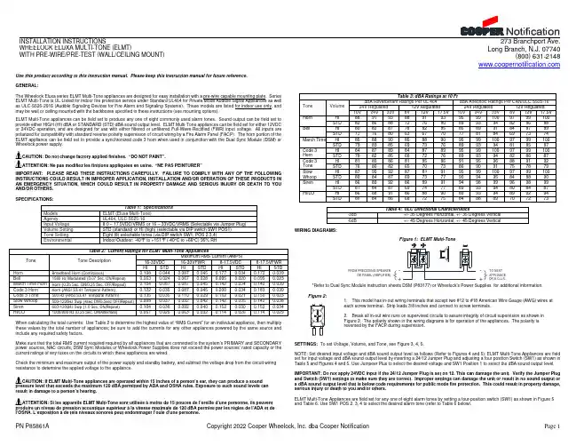
The Wheelock Eluxa series ELMT Multi-Tone appliances are designed for easy installation with a pre-wire capable mounting plate. Series ELMT Multi-Tone is UL Listed for indoor fire protection service under Standard UL464 for Private Mode Audible Signal Appliances as well as ULC-S525-2016 (Audible Signaling Devices for Fire Alarm and Signaling Systems). These models are listed for indoor use only, and may be wall or ceiling mounted with the backboxes specified in these instructions (see mounting options).
Tone
Horn Bell March Time Horn Code 3 Horn Code 3 Tone Slow Whoop Siren HI/LO
Table 2: Current Ratings for ELMT Multi-Tone Appliances
Tone Description
16-33VDC
HI/LO
HI STD
HI STD
HI STD HI STD
HI STD HI STD
HI STD
HI STD
Table 3: dBA Ratings at 10 Ft
NETGEAR Orbi路由器和卫星设置指南说明书
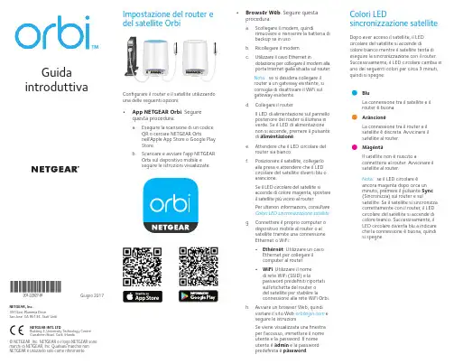
. Seguirequesta procedura:a. Eseguire la scansione di un codiceQR o cercare NETGEAR Orbinell'Apple App Store o Google Play Store.b. Scaricare e avviare l'app NETGEAROrbi sul dispositivo mobile e seguire le istruzioni visualizzate.• Browser Web . Seguire questaprocedura:a. Scollegare il modem, quindirimuovere e reinserire la batteria di backup se in uso.b. Ricollegare il modem.c. Utilizzare il cavo Ethernet indotazione per collegare il modem alla porta Internet gialla situata sul router.Nota: se si desidera collegare il router a un gateway esistente, si consiglia di disattivare il WiFi sul gateway esistente.d. Collegare il router.Il LED di alimentazione sul pannello posteriore del router si illumina in verde. Se il LED di alimentazione non si accende, premere il pulsante di alimentazione .e. Attendere che il LED circolare delrouter sia bianco.f. Posizionare il satellite, collegarloalla presa e attendere che il LED circolare del satellite diventi blu o arancione.Se il LED circolare del satellite si accende di colore magenta, spostare il satellite più vicino al router.Per ulteriori informazioni, consultare Colori LED sincronizzazione satellite .g. Connettere il proprio computer odispositivo mobile al router o al satellite tramite una connessione Ethernet o WiFi:• Ethernet . Utilizzare un cavo Ethernet per collegare il computer al router. • WiFi . Utilizzare il nome di rete WiFi (SSID) e lapassword predefiniti riportati sull'etichetta del router o del satellite per stabilire la connessione alla rete WiFi Orbi.h. Avviare un browser Web, quindivisitare il sito Web e seguire le istruzioni.Se viene visualizzata una finestra per l'accesso, immettere il nome utente e la password. Il nome utente è admin e la password predefinita è password .BluLa connessione tra il satellite e il router è buona. ArancioneLa connessione tra il router e il satellite è discreta. Avvicinare il satellite al router.MagentaIl satellite non è riuscito aconnettersi al router. Avvicinare il satellite al router.Nota: se il LED circolare è ancora magenta dopo circa un minuto, premere il pulsante Sync (Sincronizza) sul router e sulsatellite. Se il satellite si sincronizza correttamente con il router, il LED circolare del satellite si accende di colore bianco. Successivamente, il LED circolare diventa blu a indicare che la connessione è buona, quindi si spegne.Dopo aver acceso il satellite, il LED circolare del satellite si accende dicolore bianco mentre il satellite tenta di eseguire la sincronizzazione con il router. Successivamente, il LED circolare cambia in uno dei seguenti colori per circa 3 minuti, quindi si spegne:Colori LEDsincronizzazione satelliteNETGEAR INTL LTDBuilding 3, University Technology Centre Curraheen Road, Cork, IrlandaNETGEAR, Inc.350 East Plumeria DriveSan Jose, CA 95134, Stati Uniti© NETGEAR, Inc. NETGEAR e il logo NETGEAR sono marchi di NETGEAR, Inc. Qualsiasi marchio non NETGEAR è utilizzato solo come riferimento.Giugno 2017LED circolare (non mostrato nell'immagine)Pulsante Sync (Sincronizza) (utilizzato anche per la connessione WPS)Porte Internet (il satellite Orbi non include una porta Internet)Porte EthernetSupportoGrazie per aver acquistato questo prodotto NETGEAR. Visitare il sito Web/support per registrare il prodotto, ricevere assistenza, accedere ai download e ai manuali per l'utente più recenti e partecipare alla nostra community. Consigliamo di utilizzare solo risorse di assistenza NETGEAR ufficiali.Per consultare la Dichiarazione diconformità UE attuale, visitare la pagina: /app/answers/detail/a_id/11621/.Per informazioni sulla conformità alle normative, visita il sito Web all'indirizzo/about/regulatory/.Prima di collegare l'alimentazione, consultare il documento relativo alla conformità normativa.Panoramica sul router OrbiRouter Orbi (modello RBR50)Satellite Orbi (modello RBS50)Cavo EthernetAlimentatori (2)(varia in base alla regione)Panoramica sul satellite OrbiContenuto della confezione 2134128218Porta USBPulsante e LED di alimentazione Connettore di alimentazione CC Pulsante di ripristino5678。
Belimo 机械配件说明书

800-543-9038 USA 866-805-7089 CANADA 203-791-8396 LATIN AMERICA381Mechanical AccessoriesWe’ll help solve any application problem with a widerange of accessories and unparalleled customer service.The Belimo Difference●Customer Commitment.Extensive product range. Competitive project pricing. Application assistance. Same-day shipments. Free technical support. Five year warranty.●Low Installation and Life-Cycle Cost.Easy installation. Accuracy and repeatability.Low power consumption. No maintenance.●Long Service Life.Components tested before assembly. Every product tested before shipment.20+ years direct coupled actuator design.M 40024 - 05/10 - S u b j e c t t o c h a n g e . © B e l i m o A i r c o n t r o l s (U S A ), I n c .382Mechanical AccessoriesC l a m p / P o s i t i o n e r I n d i c a t o r sIND-AFB Damper Position Indicator ●●IND-AF2Damper Position Indicator ●IND-LF Damper Position Indicator ●IND-TF Damper Position Indicator●K7-2Standard AFB/NFB Clamp (1/2" to 1.05")●●K4-2 US Standard AF/NF Clamp (1/2" to 1.05")●K4-1 US Jackshaft Clamp (Up to 1.05')●K4-H US Hex Shaft Clamp (3/8" to 5/8")●K6 US Standard LF Clamp (3/8" to 1/2")●K6-1Jackshaft Clamp (1/2" to 3/4")●K8 US Standard TF Clamp●K-GM20Reversible Clamp (1/2" to 1.05”)●K-AM25Standard Clamp (1/2" to 1")●K-SA Reversible AM Clamp (2/5" to 3/4")●K-NA Reversible NM Clamp (5/16" to 3/4")●K-LM20Clamp (3/4")●K-LM16Standard Clamp (5/8")●K-LM13Clamp (1/2")●K-LM10Clamp (3/8")●K-LU Spindle Clamp (5/16" to 1/2")●L i n k a g e A c c e s s o r i e sKH-AFB Crank Arm ●●KH-AF Crank Arm●KH-AF-1 US Crank Arm for Jackshaft Applications ●KH-AFV V-Bolt Kit for KH-AF (-1) Crank Arms ●KH-LF Crank Arm●KH-LFV V-Bolt Kit for KH-LF Crank Arms ●KH-TF USCrank Arm ●AH-GMA GMB(X) Crank Arm●AH-25AMB(X) and NMB(X) Crank Arm ●●KH6Universal Crank Arm (For KG6 Ball Joint)●●●●●●●●●KH8Universal Crank Arm (For KG8 Ball Joint)●●●●●●●●●KH10Universal Crank Arm (For KG10A Ball Joint)●●●●●●●●KH12Universal Crank Arm (For KG10A Ball Joint)●●●●●●●●KG6Ball Joint (5/16")●●●●●●●●●KG8Ball Joint (5/16", 90)●●●●●●●●KG10Ball Joint for KH6 (3/8")●●●●●●●●●SH8Push Rod for KG6 & KG8 Ball Joints (36", 5/16" Dia.)●●●●●●●●●SH10Push Rod for KG10 Ball Joints (36", 3/8" Dia.)●●●●●●●●●ZG-DC1Damper Clip for Damper Blade ●●●●●●●●●ZG-DC2Damper Clip for Damper Blade●●●●●●●●● M 40024 - 05/10 - S u b j e c t t o c h a n g e . © B e l i m o A i r c o n t r o l s (U S A ), I n c .383B r a c k e t sZG-100Universal Mounting Bracket ●●●●●ZG-101Universal Mounting Bracket ●●●●●ZG-102Multiple Actuator Mounting Bracket ●●●ZG-103Universal Mounting Bracket ●●●ZG-104Universal Mounting Bracket ●●●ZG-106Universal Mounting Bracket ●ZG-107Universal Mounting Bracket ●ZG-108Universal Mounting Bracket●ZG-109Mounting Bracket for ZS-260 Housings ●●●●●●ZG-110Mounting Bracket for ZS-260 Housings ●●●●●●ZG-112Universal Mounting Bracket for LF ●ZG-113Universal Mounting Bracket for TF ●ZG-118Universal Mounting Bracket for AFB, NFB ●●Z-GMA GM to GMB(X) Retrofi t Mounting Bracket ●Z-SMA AM, SM to AMB(X) Retrofi t Mounting Bracket ●Z-NMA NM to NMB(X) Retrofi t Mounting Bracket ●C r a n k a r m A d a p t o r K i t sZG-AFB Crank Arm Adaptor Kit ●●ZG-AFB118Crank Arm Adaptor Kit●●ZG-AF US Crank Arm Adaptor Kit (includes mounting hardware)●ZG-AF108Crank Arm Adaptor Kit (includes ZG-108 & KH-AF US)●ZG-LF112Crank Arm Adaptor Kit (includes ZG-112 & KH-LF)●ZG-LF2Crank Arm Adaptor Kit (includes mounting hardware)●ZG-LFC114Trane Voyager Retrofi t Kit (includes retrofi t bracket)●ZG-ECON1Honeywell Economizer Retrofi t Kit (includes retrofi t bracket)●ZG-ECON2Honeywell Economizer Retrofit Kit ●ZG-TF112Crank Arm Adaptor Kit (includes ZG-113 & KH-TF US)●ZG-TF2Crank Arm Adaptor Kit (includes mounting hardware)●ZG-GMA Crank Arm Adaptor Kit (includes mounting hardware)●ZG-NMA Crank Arm Adaptor Kit (includes mounting hardware)●●S h a f t A d a p t o r sAV6-20Shaft Extension fi ts 1/4' to 3/4" Diameter Shafts ●●●AV8-25Shaft Extension fi ts 5/16" to 1" Diameter Shafts ●●●●●●●ZG-JSA (-1,2,3)Jackshaft Adaptors for Hollow Jackshafts ●●●●●●ZG-LMSA(-1)Shaft Adaptor ●ZG-NMSA-1Shaft Adaptor●R o t a t i o n L i m i t e r sZDB-AF2 US Angle of Rotation Limiter for AF/NF ●ZDB-LF Angle of Rotation Limiter for LF ●ZDB-TF Angle of Rotation Limiter for TF ●ZDB-LU Angle of Rotation Limiter for LU ●H o u s i n g sZS-100Weather Shield - Galvaneal ●●●●●●ZS-101Base for ZS-100●●●●●●ZS-150Weather Shield - Polycarbonate ●●●●●●ZS-260Explosion Proof Housing ●●●●●●ZS-300 (-1) (-5)NEMA 4X Housing●●●●●●ZS-TProtective Terminal Strip Cover (-T Models Only)●●●●Mechanical AccessoriesM 40024 - 05/10 - S u b j e c t t o c h a n g e . © B e l i m o A i r c o n t r o l s (U S A ), I n c .384M i s c e l l a n e o u sAF-CC US Conduit Connector ●TF-CC US Conduit Connector●●●●●●●●●●AF-P Anti-Rotation Bracket (11414)●●●LF-P Anti-Rotation Bracket (11695)●TF-P Anti-Rotation Bracket (11533)●●Z-DS1Rotary Support for Lateral Force Compensation ●●Tool-068 mm and 10 mm Wrench ●●●●●●●●●●Tool-0713 mm Wrench●Mechanical AccessoriesM 40024 - 05/10 - S u b j e c t t o c h a n g e . © B e l i m o A i r c o n t r o l s (U S A ), I n c .203-791-8396 LATIN AMERICA385Clamps / Position Indicators / Rotation Limiters K7-2 US Standard Clamp. Fits shafts 1/2" to 1.05".IND-AFBDamper Position Indicator.For damper position indication in short shaft installationsShaft Adaptors / Extensions AV8-25 Shaft Extension. For damper operating shafts. Approx. 6-5/8" [170 mm] extension for shafts1/4" to 3/4" [6 to 20 mm].The shaft adaptors listed below may be used with AFB, AFX, NFB, NFX actuators.For more information see page 410.ZG-JSA-1 ZG-JSA-2 ZG-JSA-3Non-Direct Mounting ZG-AFBCrank Arm Adaptor KitFor more information see page 401.ZG-AFB118 Crank Arm Adaptor KitFor more information see page 396.KH-AFB Crank ArmFits round shafts up to 3/4”.Mounting BracketsThe mounting brackets listed below may be used with AFB, AFX, NFB, NFX actuators.For more information see pages 395, 396 and 405.ZG-100 ZG-101 ZG-102 ZG-118 HousingsThe housings listed below may be used with AF/NF actuators.For more information see pages 411 to 415.ZS-100 ZS-150 ZS-260 ZS-300MiscellaneousAF-P Anti-Rotation T-Bracket for AF/NF.Z-AFAF, NF to AFB, AFX, NFB, NFX Retrofit Mounting BracketAFB, AFX / NFB, NFX AccessoriesZG-AFB118ZG-AFBM 40024 - 05/10 - S u b j e c t t o c h a n g e . © B e l i m o A i r c o n t r o l s (U S A ), I n c .203-791-8396 LATIN AMERICA386Clamps / Position Indicators / Rotation Limiters K4 US Clamp. Fits shafts 3/8" to 3/4".K4-1 US Jackshaft Clamp. Fits jackshafts up to 1.05".K4-2 USStandard Clamp. Fits shafts 1/2" to 1.05".K4-HHex Shaft clamp. Fits hex shafts 3/8” to 5/8”.IND-AF2Damper Position Indicator.For damper position indication in short shaft installations.ZDB-AF2 US Angle of Rotation Limiter for AF/NF actuators. Includes IND-AF2.KH-AFVV-Bolt Kit allows for direct coupling with KH-AF.Contains V-Bolt and 2 nuts.Shaft Adaptors / ExtensionsAV8-25 Shaft Extension. For damper operating shafts. Approx. 6-5/8" [170 mm] extension for shafts1/4" to 3/4" [6 to 20 mm].The shaft adaptors listed below may be used with AF/NF actuators.For more information see page 410.ZG-JSA-1 ZG-JSA-2 ZG-JSA-3Non-Direct MountingZG-AF US Crank Arm Adaptor KitFor more information see page 402.ZG-AF108 Crank Arm Adaptor KitFor more information see page 398.KH-AF Crank ArmFits round shafts up to 3/4”.KH-AF-1 US Crank Arm for Jackshaft ApplicationsFits round shafts up to 1.05".Mounting BracketsThe mounting brackets listed below may be used with AF/NF actuators.For more information see pages 395, 398, 400 and 405.ZG-100 ZG-101 ZG-102 ZG-106 ZG-107 ZG-108 HousingsThe housings listed below may be used with AF/NF actuators.For more information see pages 411 to 415.ZS-100 ZS-150 ZS-260 ZS-300Miscellaneous AF-PAnti-Rotation T-Bracket for AF/NF.AF/NF AccessoriesM 40024 - 05/10 - S u b j e c t t o c h a n g e . © B e l i m o A i r c o n t r o l s (U S A ), I n c .800-543-9038 USA 866-805-7089 CANADA 203-791-8396 LATIN AMERICA387LF AccessoriesK6 US Clamp. Fits shafts 3/8" to 1/2".K6-1 Clamp. Fits shafts 1/2" to 3/4". IND-LF Damper Position IndicatorZDB-LF Angle of Rotation Limiter for LF actuators KH-LFV V-Bolt Kit allows direct coupling with KH-LF.Contains V-Bolt and 2 nuts.Shaft Adaptors / Extensions ZG-LMSA-1Shaft Adaptor (See LM Accessories)AV6-20 Shaft Extension. For damper operating shafts. Approx. 6 ⁵⁄₈" [170 mm] extension for shafts ¼" to ¾" [6 to 20 mm] (must use K6-1 clamp).AV8-25 Shaft Extension. For damper operating shafts. Approx. 9.8" [170 mm] extension for shafts5/16" to 1" [8 to 10 mm].Non-Direct Mounting ZG-LF112-LF112ZG-LF2ZG-LFC11The mounting brackets listed below may be used with LF actuators.For more information see page 406.ZG-112 HousingsThe housings listed below may be used with LF actuators.For more information see pages 411 to 413.ZS-100 ZS-150 ZS-260MiscellaneousLF-P Anti-Rotation T-Bracket for LF.M 40024 - 05/10 - S u b j e c t t o c h a n g e . © B e l i m o A i r c o n t r o l s (U S A ), I n c .203-791-8396 LATIN AMERICA388TF AccessoriesClamps / Position Indicators / Rotation LimitersIND-TF Damper Position IndicatorZDB-TFAngle of Rotation Limiter for TF actuators.Shaft Adaptors / Extensions AV6-20Shaft Extension. For damper operating shafts.Approx. 6-5/8" [170 mm] extension for shafts 1/4" to 3/4" [6 to 20 mm].Non-Direct Mounting ZG-TF112Crank Arm Adaptor Kit.For more information see page 406.ZG-TF2Crank Arm Adaptor Kit.For more information see page 407.KH-TF US Crank Arm.With 5/16" slot (can be used with KG8 or KG10A Ball Joint).KH-TF-1 US Crank Arm.With 1/4" slot (can be used with KG6 Ball Joint).Mounting BracketsThe mounting brackets listed below may be used with TF actuators.For more information see page 406.ZG-113HousingsThe housings listed below may be used with TF actuators.For more information see page 411.ZS-100 ZS-150Miscellaneous TF-CC USConduit Connector for AFB(X) / NFB (X) / TF / GM / AM / NM / LMTF-P Anti-Rotation T-Bracket for TF / LM.M 40024 - 05/10 - S u b j e c t t o c h a n g e . © B e l i m o A i r c o n t r o l s (U S A ), I n c .203-791-8396 LATIN AMERICA389Clamps / Position Indicators / Rotation Limiters K-GM20Reversible Clamp. Fits shafts up to 1.05".Shaft Adaptors AV8-25 Shaft Extension. For damper operating shafts. Approx. 9.8" [170 mm] extension for shafts5/16" to 1" [8 to 10 mm].The shaft adaptors listed below may be used with GM actuators.For more information see page 410.ZG-JSA-1 ZG-JSA-2 ZG-JSA-3Non-Direct Mounting ZG-GMA Crank Arm Adaptor KitFor more information see page 403.AH-GMA Crank ArmMounting BracketsThe mounting brackets listed below may be used with GM actuators.For more information see pages 395 and 405.ZG-100 ZG-101 ZG-102 ZG-103 ZG-104HousingsThe housings listed below may be used with GM actuators.For more information see pages 411 to 415 and page 372.ZS-100 ZS-150 ZS-260 ZS-300 ZS-T Miscellaneous TF-CC US Conduit Connector for AFB, AFX / NFB, NFX / TF / GM / AM / NM / LM Z-GMAGM to GMB, GMX Retrofit Mounting Bracket.23681-00001GK Adaptor. For short shafting to connect to auxiliary switch or potentiometer.M 40024 - 05/10 - S u b j e c t t o c h a n g e . © B e l i m o A i r c o n t r o l s (U S A ), I n c .203-791-8396 LATIN AMERICA390Clamps / Position Indicators / Rotation Limiters K-AM25Standard Reversible Clamp. Fits shafts up to 1.05".K-SAReversible Clamp. Fits shafts up to 3/4".Non-Direct Mounting ZG-NMA Crank Arm Adaptor KitFor more information see page 404.AH-25Crank ArmShaft Adaptors / Extensions AV8-25Shaft Extension. For damper operating shafts.Approx. 9.8" [170 mm] extension for shafts 5/16" to 1" [8 to 10 mm].The shaft adaptors listed below may be used with AM actuators.For more information see page 410.ZG-JSA-1 ZG-JSA-2 ZG-JSA-3Mounting BracketsThe mounting brackets listed below may be used with AM actuators.For more information see page 405.ZG-100 ZG-101 ZG-103 ZG-104HousingsThe housings listed below may be used with AM actuators.For more information see pages 411 to 415 and page 372.ZS-100 ZS-150 ZS-260 ZS-300 ZS-T Miscellaneous TF-CC US Conduit Connector for AFB, AFX / NFB, NFX / TF / GM / AM / NM / LM Z-SMAAM, SM to AMB, AMX Retrofit Mounting BracketAM/AMQ AccessoriesM 40024 - 05/10 - S u b j e c t t o c h a n g e . © B e l i m o A i r c o n t r o l s (U S A ), I n c .203-791-8396 LATIN AMERICA391Clamps / Position Indicators / Rotation Limiters K-AM25 Standard Reversible Clamp. Fits shafts up to 1.05".K-NAReversible Clamp. Fits shafts up to 3/4".Non-Direct MountingZG-NMACrank Arm Adaptor KitFor more information see page 404.AH-25Crank ArmShaft Adaptors / Extensions ZG-NMSA-1Short Shaft ExtensionAV8-25 Shaft Extension. For damper operating shafts. Approx. 9.8" [170 mm] extension for shafts 5/16" to 1" [8 to 10 mm].The shaft adaptors listed below may be used with NM actuators.For more information see page 410.ZG-JSA-1 ZG-JSA-2 ZG-JSA-3Mounting BracketsThe mounting brackets listed below may be used with NM actuators.For more information see page 405.ZG-103 ZG-104HousingsThe housings listed below may be used with NM actuators.For more information see pages 411 and page 372.ZS-100 ZS-150 ZS-T Miscellaneous TF-CC US Conduit Connector for AFB, AFX / NFB, NFX / TF / GM / AM / NM / LM Z-NMANM to NMB, NMX Retrofit Mounting BracketNM/NMQ AccessoriesM 40024 - 05/10 - S u b j e c t t o c h a n g e . © B e l i m o A i r c o n t r o l s (U S A ), I n c .203-791-8396 LATIN AMERICA392LM/LMQ AccessoriesClamps / Position Indicators / Rotation Limiters K-LM20Clamp. Fits shafts up to 3/4".K-LM16Standard Clamp. Fits shafts up to 5/8". K-LM12Clamp. Fits shafts up to 1/2".K-LM10Clamp. Fits shafts up to 3/8".Shaft Adaptors / Extensions ZG-LMSA Shaft Extension ZG-LMSA-1 Shaft ExtensionAV6-20Shaft Extension. For damper operating shafts.Approx. 6 ⁵⁄₈" [170 mm] extension for shafts ¼" to ¾" [6 to 20 mm] (must use K6-1 clamp).HousingsThe housings listed below may be used with LM actuators.For more information see pages 411 and 372.ZS-100 ZS-150 ZS-T Miscellaneous TF-CC US Conduit Connector for TF / GM / AM / NM / LM TF-PAnti-Rotation T-Bracket for TF / LM.M 40024 - 05/10 - S u b j e c t t o c h a n g e . © B e l i m o A i r c o n t r o l s (U S A ), I n c .203-791-8396 LATIN AMERICA393Crank arms / Ball Joints / Push RodsKH6 Universal Crank Arm (For more information see Universal Accessories).KH8 Universal Crank Arm(For more information see Universal Accessories).KG6Ball Joint (Zinc Plated)(For more information see Universal Accessories).KG8 Ball Joint (Galvanized)(For more information see Universal Accessories).KG10 BallJoint (Zinc Plated) (For more information see Universal Accessories).SH8 Push Rod(For more information see Universal Accessories).SH10 Push Rod(For more information see Universal Accessories).Miscellaneous TF-CC US Conduit Connector for TF / GM / AM / NM / LM Z-DS1Rotary Support for Lateral Force Compensation Clamps / Position Indicators / Rotation LimitersK-LU Spindle Clamp. Fits shafts 5/16" to 1/2".ZDB-LU Angle of Rotation Limiter for LU.HousingsThe housings listed below may be used with LU actuators.For more information see pages 411 and 372.ZS-100 ZS-150 ZS-T Miscellaneous TF-CC USConduit Connector for TF / GM / AM / NM / LMAH/AHQ/AHK, LH/LHQ and LU AccessoriesZ-DS1Rotary Support for Lateral Force Compensation Z-KSA 5/16" Shaft Clevis Z-KSC 3/8" Shaft ClevisM 40024 - 05/10 - S u b j e c t t o c h a n g e . © B e l i m o A i r c o n t r o l s (U S A ), I n c .CANADA 203-791-8396 LATIN AMERICA394Universal AccessoriesDimensions (Inches [MM])(Inches [MM])Universal Crank arms KH6 Zinc plated steel. Slot width 1/4” (6.2mm). For damper shafts:3/8” to 11/16” dia. (10 to 18mm) or 3/8” to 9/16” sq. (10 to 14mm).Uses KG6 Ball Joint.KH8 Zinc plated steel. Slot width 21/64” (8.2mm).For damper shafts:3/8” to 11/16” dia. (10 to 18mm) or 3/8” to 9/16” sq. (10 to 14mm).Uses KG8 or KG10A Ball Joint.KH10 Zinc plated steel. Slot width 21/64” (8.2mm). For damper shafts:9/16” to 1.05" dia. (14 to 25mm).Uses KG10A Ball Joint.KH12 Zinc plated steel. Slot width 21/64” (8.2mm). For damper shafts: 3/4” to 1" dia. (20 to 25mm). Uses KG10A Ball Joint.Ball JointsKG6 For KH6 Universal Crank Arm. Zinc plated steel. For 5/16” dia. rod (8mm). The KG6 ball joint is only recommended up to 70 in-lbs. (8Nm)KG8 For KH8 Universal Crank Arm Galvanized steel. 90° angle.For 5/16” dia. rod (8mm).KG10A Zinc Plated SteelUsed with following crank arms: KH8 = 3/8” (10mm)Push Rods SH8 For KG6 and KG8 Ball Joints. 36” length, 5/16” dia.SH10 For KG10 Ball Joints. 36” length, 3/8” dia.Damper ClipsZG-DC1Mounts to Damper Blades – 3.5”ZG-DC2Mounts to Damper Blades – 6”The ZG-DC1 and ZG-DC2 damper clips are designed to mount to damper blades and work as crank arms in damper linkage applications. The ZG-DC1 is designed to be used in applications where the actuator islocated in front of the damper. The ZG-DC2 is designed to be used when the actuator is located above or below the damper.KH10ZG DC ZG-DC2ZG-DC2 clipZG-AF USZG DC ZG-DC1ZG-DC1 clip ZG-106 orZG-107 with KH-AFKH12M 40024 - 05/10 - S u b j e c t t o c h a n g e . © B e l i m o A i r c o n t r o l s (U S A ), I n c .800-543-9038 USA 203-791-8396 LATIN AMERICA / CARIBBEANP 10414 - 05/13 - S u b j e c t t o c h a n g e . © B e l i m o A i r c o n t r o l s (U S A ), I n c .ZG-102 Multiple Actuator Mounting BracketFor GK, AF and GM Series ActuatorsThe major advantage with this method is it requires less mounting area. The manual override, if available, cannot be used in this configuration.FIGURE BThe major advantages are that a shorter shaft is required and a lower profile isachieved.OTHER CRANK ARM ADAPTOR KITS AND UNIVERSAL MOUNTING BRACKETSMOUNTING BRACKET*SUITABLE ACTUATOR ZG-100, ZG-101EF ZG-100, ZG-101AF, NF ZG-AFB118ZG-118 (included)AF, NF ZG-LF112ZG-112 (Included)LF N/A LF ZG-LFC114N/ALF ZG-ECON1ZG-112 (Included)LF ZG-ECON2ZG-112 (Included)LF ZG-TF112ZG-113 (Included)TF N/ATF ZG-100, ZG-101, ZG-103, ZG-104GK, GM ZG-100, ZG-101, ZG-103, ZG-104NM, AM*Unless otherwise noted, mounting brackets are not included in crank arm adaptor kits.7"[77.8]3-3/8"[85.7]5 3/4"[146.1]1-15/16"[49]Material 12 GA Galvanized Weight1.8 lbs.800-543-9038 USA 866-805-7089 CANADA 203-791-8396 LATIN AMERICA396ApplicationThe ZG-AFB118 Crank Arm Adaptor Kit is designed for applications where the actuator cannot be mounted directly to the damper shaft. It may be used for outside or inside the duct mounting.The ZG-AFB118 Crank Arm Adaptor Kit includes:1 ZG-118 Mounting Bracket1 KH-AFB Crank Arm with Retaining Clip2 Bolts with NutsNOTE:May require crank arm and ball jointsThe ZG-118 is provided with hole patterns to mount the AFB, AFX, NFB and NFX actuators in either a horizontal or vertical position to meet space requirements. The KH-AFB crank arm is required to fully convert the AFB, AFX, NFB or NFX for crank arm operation.The ZG-118 is designed to mount the AFB, AFX, NFB and NFX actuators in the same mounting locations as common foot mounted, crank arm style actuators. Hole patterns in the base match common Honeywell™, Siebe™ (Barber Colman™) and Johnson Controls™ actuators for easy retrofit.USE WHEN REPLACING THESE ACTUATORSHoneywell M91… M955… M975… M945… M965… M8…Johnson M110… M130… M150… M120… M140…Barber Coleman MA3… MA4… MA5…ZG-AFB118 Crank Arm Adaptor KitFor AFB, AFX, NFB and NFX Series ActuatorsDimensions (Inches [mm])5.5"2.6"5.87"Material: 12 GA Galvanized Weight: 2.0 lbs. (0.8 kg)OTHER CRANK ARM ADAPTOR KITSAND UNIVERSAL MOUNTING BRACKETSKIT MOUNTING BRACKET*ACTUATOR USED WITH ZG-AFB NA AFB, AFX, NFB, NFX ZG-AFB118ZG-118AFB, AFX, NFB, NFX ZG-AF108ZG-108 (Included)AF ZG-AF US ZG-100, ZG-101AF ZG-LF112ZG-112 (Included)LF ZG-LF2NA LF ZG-LFC114NALF ZG-ECON1ZG-112 (Included)LF ZG-ECON2ZG-112 (Included)LF ZG-TF112ZG-113 (Included)TF ZG-TF2NATF ZG-GMA ZG-101, ZG-101, ZG-103, ZG-104GM ZG-NMAZG-101, ZG-101, ZG-103, ZG-104NM, AMNAZG-106AF NAZG-107AF*Unless otherwise noted, mounting brackets are not included in crank arm adaptor kits.M 40024 - 05/10 - S u b j e c t t o c h a n g e . © B e l i m o A i r c o n t r o l s (U S A ), I n c .800-543-9038 USA866-805-7089 CANADA203-791-8396 LATIN AMERICA397ZG-AFB118 Crank Arm Adaptor KitMounting Positions for Typical ReplacementsBarber Colman™ MA Type - Vertical Barber Colman™ MA Type - Horizontal (left)Barber Colman™ MA Type - Horizontal (right)Black holes represent correct bolt locationsHoneywell™ Mod. IV Type - Vertical Honeywell™ Mod. IV Type - Horizontal (left)Honeywell™ Mod. IV Type - Horizontal (right)Johnson Controls™ 100 Series Type and Honeywell™ Mod. III Type - VerticalJohnson Controls™ 100 Series Type and Honeywell™ Mod. III Type - Horizontal (left)Johnson Controls™ 100 Series Type and Honeywell™ Mod. III Type - Horizontal (right)M 40024 - 05/10 - S u b j e c t t o c h a n g e . © B e l i m o A i r c o n t r o l s (U S A ), I n c .800-543-9038 USA 866-805-7089 CANADA 203-791-8396 LATIN AMERICA398ApplicationThe ZG-AF108 Crank Arm Adaptor Kit is designed for applications where the actuator cannot be mounted directly to the damper shaft. It may be used for outside or inside the duct mounting.The ZG-AF108 Crank Arm Adaptor Kit includes:1 ZG-108 Mounting Bracket1 KH-AF Crank Arm with Retaining Ring 4 Bolts with NutsNOTE:May require crank arm and ball jointsThe ZG-108 is provided with hole patterns to mount the AF series actuators in either a horizontal or vertical position to meet space requirements.The ZG-108 Mounting Bracket is designed to mount the AF series actuator in the same mounting locations as common foot mounted, crank arm style actuators. Hole patterns in the base match common Honeywell™, Siebe™ (Barber Coleman™), and Johnson Controls™ actuators for easy retrofit. USE WHEN REPLACING THESE ACTUATORSHoneywell M91… M955… M975… M945… M965… M8…Johnson M110… M130… M150… M120… M140…Barber ColemanMA3… MA4… MA5…ZG-AF108 Crank Arm Adaptor KitFor AF Series ActuatorsZGZG-108KH-AFDimensions (Inches [mm])5 7/8" [149]2" [50.8]5 1/2" [139.7]Material 12 GA Galvanized Weight 1.0 lbs. (0.45 kg)KIT MOUNTING BRACKET*ACTUATOR USED WITH ZG-AFB NA AFB, AFX, NFB, NFX ZG-AFB118ZG-118AFB, AFX, NFB, NFX ZG-AF108ZG-108 (Included)AF ZG-AF US ZG-100, ZG-101AF ZG-LF112ZG-112 (Included)LF ZG-LF2NA LF ZG-LFC114NALF ZG-ECON1ZG-112 (Included)LF ZG-ECON2ZG-112 (Included)LF ZG-TF112ZG-113 (Included)TF ZG-TF2NATF ZG-GMA ZG-101, ZG-101, ZG-103, ZG-104GM ZG-NMA ZG-101, ZG-101, ZG-103, ZG-104NM, AM NA ZG-106AF NAZG-107AF*Unless otherwise noted, mounting brackets are not included in crank arm adaptor kits.M 40024 - 05/10 - S u b j e c t t o c h a n g e . © B e l i m o A i r c o n t r o l s (U S A ), I n c .399ZG-AF108 Crank Arm Adaptor KitMounting Positions for Typical ReplacementsJohnson Control™ 100 Series Type and Honeywell™ Mod. III TypeVerticalJohnson Control™ 100 Series Type and Honeywell™ Mod. III TypeHorizontal (left)Johnson Control™ 100 Series Type and Honeywell™ Mod. III TypeHorizontal (right)Black holes represent correct bolt locations.Honeywell™ Mod. IV Type- Vertical Honeywell™ Mod. IV Type - Horizontal (left)Honeywell™ Mod. IV Type - Horizontal (right)Barber Colman™ MA Type - Vertical Barber Colman™ MA Type - Horizontal (left)Barber Colman™ MA Type - Horizontal (right)M 40024 - 05/10 - S u b j e c t t o c h a n g e . © B e l i m o A i r c o n t r o l s (U S A ), I n c .800-543-9038 USA 866-805-7089 CANADA 203-791-8396 LATIN AMERICA400ZG-106 and ZG-107 Universal Mounting BracketsFor AF Series ActuatorsApplicationThe ZG-106 and ZG-107 Universal Mounting Brackets are designed for applications where the actuator cannot be mounted directly to the damper shaft. They may be used for outside or inside the duct mounting.The ZG-106 and ZG-107 is provided with hole patterns to mount the AF series actuators in either a horizontal or vertical position to meet space requirements.The KH-AF crank arm is required to fully convert the AF for crank arm operation.The ZG-106 and ZG-107 are designed to mount the AF series actuators in the same mounting locations as common foot mounted, crank arm style actuators. Hole patterns in the base match common Honeywell™, Siebe™ (Barber Coleman™), and Johnson Controls™ actuators for easy retrofit.The ZG-106 is designed to place the KH-AF crank arm in the same relative position as the Honeywell™ Mod IV actuators. The ZG-107 is designed to place the crank arm in the same relative position as the Honeywell™ Mod III E THE ZG-106 WHEN REPLACING THESE ACTUATORS Honeywell Mod IV M91… M945…M955… M965… M975… M8…USE THE ZG-107 WHEN REPLACING THESE ACTUATORS Honeywell Mod IIIKIT MOUNTING BRACKET* ACTUATOR USED WITH ZG-AFB NA AFB, AFX, NFB, NFX ZG-AFB118ZG-118AFB, AFX, NFB, NFX ZG-AF108ZG-108 (Included)AF ZG-AF US ZG-100, ZG-101AF ZG-LF112ZG-112 (Included)LF ZG-LF2NA LF ZG-LFC114NALF ZG-ECON1ZG-112 (Included)LF ZG-ECON2ZG-112 (Included)LF ZG-TF112ZG-113 (Included)TF ZG-TF2NATF ZG-GMA ZG-101, ZG-101, ZG-103, ZG-104GM ZG-NMA ZG-101, ZG-101, ZG-103, ZG-104NM, AM NA ZG-106AF NAZG-107AF*Unless otherwise noted, mounting brackets are not included in crank arm adaptor kits.Dimensions (Inches [mm])5-1/2" [139.7]A2-1/4" [57]BA B ZG-106 1.50" 1.02"ZG-107 2.25"1.77"Material 12 GA Galvanized WeightZG-1060.7 lbs.ZG-1070.9 lbs.M 40024 - 05/10 - S u b j e c t t o c h a n g e . © B e l i m o A i r c o n t r o l s (U S A ), I n c .。
P12智能手表使用说明书

Aprire l’app e fare click su "accoppia lo smart watch" per trovare il modello P12 (figura 1), fare click su “connetti” e la connessione verrà effettuata (figura 2):
2)、 Accedere alla pagina di ricerca Bluetooth del telefono cellulare, effettuare la ricerca e connettersi a P12_Audio
Scorrere sullo schermo per accedere al menu delle funzioni
Cliccare per per saltare alla modalità interfaccia musicale Saltare alla modalità TWS Interfaccia musicale
Scorrere verso sinistra al menu delle funzioni
telefono cellulare e attivare l'interruttore di notifica di Whatsapp, Facebook, Telefono, SMS ecc.)
Perché il braccialetto si disconnette spesso? Salve, questa situazione potrebbe essere causata dal blocco o dalla pulizia del software da parte del sistema di telefonia mobile, che impedisce al software di funzionare normalmente. Si prega di impostare il telefono cellulare in base alle diverse marche di telefoni cellulari. Imposta una whitelist sui telefoni Android e abilita la gestione dell'avvio automatico; Impostazioni del telefono OPPO: 1.Aprire OPPO Mobile Manager-fare clic su Permessi Privacy-clic su Gestione autorizzazioni applicazioni-cliccare su APP-apri mi fido di questa applicazione 2.Aprire l'APP-fai clic sul pulsante a sfioramento in basso a sinistra del telefono-fare clic sul lucchetto in alto a sinistra dell'APP 3.Attivare la gestione dell'autoaccensione-fare clic sul gestore del telefono-fare clic sulla gestione dell'avvio automatico-aprire l'APP
Belimo B261 抄录说明书
B261•ApplicationStainless Steel Ball and StemTechnical dataFunctional dataValve Size 2.5" [65]Fluidchilled or hot water, up to 60% glycol Fluid Temp Range (water)0...212°F [-18...100°C]Body Pressure Rating 400 psi Close-off pressure ∆ps 100 psiFlow characteristic equal percentage Servicing maintenance-free Flow Pattern 2-way Leakage rate0% for A – AB Controllable flow range 75°Cv60 Body pressure rating note 400 psiCv Flow RatingA-port: as stated in chart B-port: 70% of A – AB Cv MaterialsValve body Nickel-plated brass body Stem seal EPDM (lubricated)SeatPTFEPipe connection NPT female ends O-ring EPDM (lubricated)Ballstainless steel Suitable actuatorsNon-SpringARB(X)Safety notesWARNING: This product can expose you to lead which is known to the State of California to cause cancer and reproductive harm. For more information go to Product featuresThis valve is typically used in air handling units on heating or cooling coils, and fan coil unit heating or cooling coils. Some other common applications include Unit Ventilators, VAV box re-heat coils and bypass loops. This valve is suitable for use in a hydronic system with variable flow.Flow/Mounting detailsB261 DimensionsDimensional drawingsARB, ARXA B C D E F H110.1" [257] 5.6" [141]8.0" [203] 6.0" [152] 2.8" [71] 2.8" [71] 1.9" [48]AFRB, AFRXA B C D E F11.5" [293] 5.6" [141]8.6" [219] 6.6" [168] 2.0" [51] 2.0" [51]ARQB, ARQXA B C D E F H1H29.9" [251] 4.2" [107]8.1" [206] 6.1" [155] 2.3" [58] 2.3" [58]0.8" [20]0.6" [15]AFRB N4, AFRX N4A B D E F11.4" [289] 5.6" [141]8.0" [203] 2.4" [62] 2.4" [62]ARB N4, ARX N4, NRB N4, NRX N4A B D E F11.4" [289] 5.6" [141]8.0" [203] 3.1" [80] 3.1" [80]A B C D E F H1H29.9" [251] 4.2" [107]8.1" [206] 6.1" [155] 2.3" [58] 2.3" [58]0.8" [20]0.6" [15]A B D E F11.4" [289] 5.6" [141]8.0" [203] 3.1" [80] 3.1" [80]AFRB24-S On/Off, Spring Return, AC/DC 24 VTechnical dataElectrical data Nominal voltage AC/DC 24 VNominal voltage frequency50/60 HzPower consumption in operation 5 WPower consumption in rest position 2.5 WTransformer sizing7.5 VA (class 2 power source)Auxiliary switch 2 x SPDT, 3 A resistive (0.5 A inductive) @ AC 250 V,one set at 10°, one adjustable 10...90°Switching capacity auxiliary switch 3 A resistive (0.5 A inductive) @ AC 250 VElectrical Connection(2) 18 GA appliance cables with 1/2" conduitconnectors, 3 ft [1 m],Overload Protection electronic throughout 0...95° rotationFunctional data Direction of motion motor selectable by ccw/cw mountingDirection of motion fail-safe reversible with cw/ccw mountingManual override 5 mm hex crank (3/16" Allen), suppliedAngle of rotation90°Running Time (Motor)75 sRunning time fail-safe<20 sNoise level, motor45 dB(A)Noise level, fail-safe62 dB(A)Position indication MechanicalSafety data Degree of protection IEC/EN IP54Degree of protection NEMA/UL NEMA 2 UL Enclosure Type 2Agency Listing cULus acc. to UL60730-1A/-2-14, CAN/CSAE60730-1:02, CE acc. to 2014/30/EU and 2014/35/EU; Listed to UL 2043 - suitable for use in airplenums per Section 300.22(c) of the NEC andSection 602.2 of the IMCQuality Standard ISO 9001Ambient temperature-22...122°F [-30...50°C]Storage temperature-40...176°F [-40...80°C]Ambient humidity max. 95% r.H., non-condensingServicing maintenance-freeWeight Weight 5.7 lb [2.6 kg]Electrical installationINSTALLATION NOTESActuators with appliance cables are numbered.Provide overload protection and disconnect as required.AFRB24-STwo built-in auxiliary switches (2x SPDT), for end position indication, interlock control, fan startup, etc.Actuators may be powered in parallel. Power consumption must be observed.Parallel wiring required for piggy-back applications.Apply only AC line voltage or only UL-Class 2 voltage to the terminals of auxiliary switches. Mixed orcombined operation of line voltage/safety extra low voltage is not allowed.Meets cULus requirements without the need of an electrical ground connection.Warning! Live Electrical Components!During installation, testing, servicing and troubleshooting of this product, it may be necessary to workwith live electrical components. Have a qualified licensed electrician or other individual who has beenproperly trained in handling live electrical components perform these tasks. Failure to follow all electricalsafety precautions when exposed to live electrical components could result in death or serious injury.On/Off Auxiliary Switches。
IMC02R 欧元 英镑伪币检测器用户手册说明书
Munbyn,More choice for your growing businessIMC02R Counterfeit DetectorUser ManualVersion 1.01Version 1.01Contents1.0. Unpack and Installation122333445681.0. Unpack and Installation 3.0.Technical Parameters1.1. Packing List1.2. Installation Instructions 2.1. Display Appearance 2.2. Turn On/Off the Machine 2.3. B utton Functions 2.3.1 Advance 2.3.2 Return2.4. Inserting the Banknote Correctly 2.5. EUR/GBP Currency Detecting2.6. Inaccurate Detection of Currency Detector 2.0.Operating InstructionsVersion 1.01IMC02R Counterfeit Detector User Manual Page 1 of 9When you receive the package, open and check the packing list in the package.1.1. Packing ListItem NamePicture Quantity (pcs)DescriptionCounterfeit Detector Battery Power Adapter User ManualBill Counterfeit Detector11.1V 500mAh rechargeable battery Power Adaptor1111Table-1 Packing ListVersion 1.01IMC02R Counterfeit Detector User Manual Page 3 of 9Version 1.01IMC02R Counterfeit Detector User ManualPage 2 of 9Turn on the IMC02R by switch the power switch button to on, the screen will light up and the machine will start self-testing. If the self-test is successful, all of the screen lights will be on.Turn off the IMC02R by switch the power switch to off. When the screen lights off, it means the machine has been turned off successfully.Figure 2-2 IMC02R Power Interface2.2. Turn On/Off the Machine2.3. Button Functions 2.0. Operating InstructionsFigure 2-1 IMC02R Display Appearance2.1. Display AppearanceDC Power : Connect the power adapter to a 110V or 220V outlet, then connect the terminal to the machine’s DC12V input socket.Lithium Battery: When the battery was fully charged, the machine can work without power adapter.1.2. Power SupplyBanknote DirectionIndicatorBanknote Direction:AdvanceBanknote Direction:ReturnBanknote Detecting Result:Pass or FailPower switchThe banknote exit direction, advance.2.3.1. AdvanceVersion 1.01IMC02R Counterfeit Detector User ManualPage 5 of 9Version 1.01IMC02R Counterfeit Detector User ManualPage 4 of 9As shown in the following figures, please remove the banknote feeding limit block to adjust the banknote with bigger size.2.5. EUR/GBP Currency DetectingFigure 2-3 Banknote Insertion2.4. Inserting the Banknote CorrectlyFigure 2-4 Banknote InsertionThe banknote exit direction, return.As shown in the following pictures, please insert the banknotes in the left side. If a banknote was incorrectly inserted, the IMC02R may refuse it and alert.2.3.2.ReturnThe banknote feedinglimit blockFigure 2-5 EUR Banknote DetectingFigure 2-6 Bill Damaged Ways 2.6. Inaccurate Detection of Currency DetectorThere are several conditions to affect the accuracy of the currency detector.1) The bill size is out of the range according to IMC02R specification.2) The banknote is damaged with different ways such as lack of corner, tape, hole, tear and folded. As shownin Figure 2-6, it is not recommended to count this kind of bills.3) Other abnormal operation or there is unknown thing inside the IMC02R.If something inside the IMC02R,you need to open the front cover to check, and clean the internal sensors.Version 1.01IMC02R Counterfeit Detector User Manual Page 7 of 9 Version 1.01IMC02R Counterfeit Detector User Manual Page 6 of 9Scan the QR code for Facebookonline chat Contact usIf you meet any problem during using the IMC02R, please contact us.******************+86178****1067+1 403 477 19113.0. Technical ParametersCounterfeit Detection MG (Magnetic), IR (Infrared), UV (Ultraviolet) Error Detection Image, paper quality, size, thickness detection Available currencies USD, EURDisplay Direction, Detection Result IndicationButton Advance/ReturnInterface USB, software upgrade interfaceDetecting Speed<0.5 seconds/piecePower Consumption<10WPower Supply Battery AC 100V-240V 50-60Hz or DC 12V/1.0ARechargeable lithium battery 11.1V / 500 mAhCertifications CE, FCC, ROHSOperating Temperature0°C - 40°CStorage Temperature-20°C - 65°CT able 3-1 Technical ParameterVersion 1.01IMC02R Counterfeit Detector User Manual Page 9 of 9Version 1.01IMC02R Counterfeit Detector User Manual Page 8 of 9。
Belimo 空气控制系统技术文档说明书
T e c h .D o c - 01/20 - S u b j e c t t o c h a n g e . © B e l i m o A i r c o n t r o l s (U S A ), I n c .Input/Output SpecificationsType Name Description Electrical Specifi cation Input RSupply HotAC 24 V, ± 20%, 50/60HzInputG/OCCFan Signal (occupied)On/Off, AC 24 V, ± 20%, 50/60Hz Input C Supply Common CommonInput Y1Cooling requirement Stage 1On/Off, AC 24 V, ± 20%, 50/60Hz Input Y2Cooling requirementStage 2On/Off, AC 24 V, ± 20%, 50/60Hz Input W1/O/B Heating requirement Stage 1On/Off, AC 24 V, ± 20%, 50/60Hz Input SAT ±Supply Air TemperatureSensorType: 10K NTC (Type II thermistor)Input OAT ±Outdoor Air Temperature Type: 10K NTC (Type II thermistor)InputOAH ±Outdoor Air HumidityDC 0...10 VAuto Detection: Sensor present if voltage 0.5...10 VInput RAT ±Return Air Temperature Type: 10K NTC (Type II thermistor)Input RAH ±Return Air Humidity DC 0...10 VAuto Detection: Sensor present if voltage 0.5 (10V)Output CC1Compressor 1RTU Stage 1Mechanical Cooling Circuitry 100'000 cycles @ inrush currentof 3A, normal current 1.5A Impedance for Auto detection @ 24 V:<60O Ω @ 60Hz <80O Ω @ 50HzOutputCC2Compressor 2RTU Stage 2Mechanical CoolingCircuitry100'000 cycles @ inrush currentof 3A, normal current 1.5A Impedance for Auto detection @ 24 V:<60O Ω @ 60Hz <80O Ω @ 50HzOutput Act 1Actuator supply common Common Output Act 2Actuator supply hot AC 24 V, 50/60Hz Output Act 3Actuator control output DC 2...10 V Input Act 5Actuator feedback signalDC 2...10 VInstallationYou can mount the ZIP Economizer in any orientation; it is recommended that you mount it in a position that will allow full utilization of the LCD and key pad and proper clearance for installation, servicing, wiring, and removal.Take the overall dimensions of 6.63" [168.5] x 7.12" [181] x 2" [50.8] and mount in the interior of the RTU in a convenient location that you can access. Secure the ZIP utilizing #8 self-tapping screws (included). A minumum of two tabs need to be secured, one which is a top tab. Ideally secure all four tabs. Wire the electrical connection using ¼” female insulated spade connectors to prevent corrosion.Technical DataPower supplyAC 24 V ± 20%, 50/60 Hz; Class 2 power source Power consumption rating*4 VA base control (ECON-ZIP-BASE)5.5 VA base control with Energy Module (ECON-ZIP-BASE + ECON-ZIP-EM)5 VA base control with Communication Module (ECON-ZIP-BASE + ECON-ZIP-COM)6.5 VA base with Energy Module andCommunication Module. (ECON-ZIP-BASE + ECON-ZIP-EM + ECON-ZIP-COM)Rated impulse voltage 330 VConnectors ¼” male spade connectors Environmental RoHS, conformally coated Software classA Control pollution degree 3Temperature input signal NTC 10k Ω, Type IIHumidity5 to 95% RH non-condensingHumidity input signal DC 0...10 V; corresponds to 0...100%HousingNEMA 1Housing materialUL94-5VAAmbient temperature range -40...+158°F [-40...+70°C]Storage temperature range -40...+176°F [-40...+80°C]Display2x16 character LCD; LED backlight; transflectiveDisplay op. range**-22...+176°F [-30...+80°C]Agency listing cULus acc. to UL873, CAN/CSA C22.2, No. 24-93Energy code compliantASHRAE 90.1, CA Title 24, NECBDimensions (Inches [mm])7.12 [181]2.42 [61.6]0.18 [4.6]6.04 [153.4]5.5 [140]6.63 [168.5]2 [50.8]0.16 [4.1]ECON-ZIP-BASEZIP Economizer™ Base Module* The power consumption is for the control only and does not include connected loads such as actuator, compressors, fans, and sensors. For transfomer sizing, the power consumption of these attached components must be included.** At low temperature the display has decreased response time. Below -22°F [-30°C] it will not function.T e c h .D o c - 01/20 - S u b j e c t t o c h a n g e . © B e l i m o A i r c o n t r o l s (U S A ), I n c .ECON-ZIP-BASEZIP Economizer™ Base Module Wiring DiagramsR CG OCC W1O/B Y1Y2ACT1ACT2ACT3ACT5R C R CG/OCC W1/O/B Y1Y2CC1CC2OAT+OAT-OAH+OAH-SAT+SAT-RAT+RAT-RAH+RAH--SR1 -Common2 + Hot3 Y Input, 2 to 10V 5 U Output, 2 to 10VACT 1ACT 2ACT 3ACT 5R CY1Y2ECON-ZIP-10K Supply Air TempSAT +SAT -OAT + OAT -CC1CC2OCC W1RTU Stage 1 Mechanical CoolingCircuitryRTU Stage 2 Mechanical CoolingCircuitryECON-ZIP-10K Outside Air TempTHERMOSTATRTU TERMINALECON-ZIP-BASE575251535659R CG OCCW1O/B Y1Y2ACT1ACT2ACT3ACT5R C R CG/OCC W1/O/B Y1Y2CC1CC2OAT+OAT-OAH+OAH-SAT+SAT-RAT+RAT-RAH+RAH--SR1 -Common2 + Hot3 Y Input, 2 to 10V 5 U Output, 2 to 10VACT 1ACT 2ACT 3ACT 5R CY1Y2ECON-ZIP-10K Supply Air Temp SAT +SAT -CC1CC2OCC W1RTU Stage 1 Mechanical CoolingCircuitry RTU Stage 2 Mechanical CoolingCircuitryECON-ZIP-TH Outside Air EnthalpyT (+)T (-)24 V (R)RH (+)RH (-)OAT + OAT -OAH + OAH - RECON-ZIP-BASETHERMOSTATRTU TERMINAL57505251535659When the thermostat is not equipped with occupancy control, "Fan On" output "G" shall be wired to the ECON-ZIP-BASE.W1 must be wired for Heat Pump operation if conventional thermostat is used in conjunction with Defrost Board. If Thermostat and RTU use O/B control reversing valve position, O/B must be wired to W1 on ECON-ZIP-BASE.Existing refrigeration safety devices may exist, consult RTU wiring diagram515253If RTU is not a Heat Pump using a conventional thermostat and it is desired to record heating operation hours, connect W1 to ECON-ZIP-BASE.56Actuators can be mounted in parallel with the ACT3 output from the ZIP Economizer. The ACT5 feedback input should be wired to the Outside Air damper actuator feedback wire.57Iso relay may be required with certain RTU manufacturers.59Power source should be the same as ECON-ZIP-BASE.50When the thermostat is not equipped with occupancy control, "Fan On" output "G" shall be wired to the ECON-ZIP-BASE.Existing refrigeration safety devices may exist, consult RTU wiring diagram5153If RTU is not a Heat Pump using a conventional thermostat and it is desired to record heating operation hours, connect W1 to ECON-ZIP-BASE.56W1 must be wired for Heat Pump operation if conventional thermostat is used in conjunction with Defrost Board. If Thermostat and RTU use O/B control reversing valve position, O/B must be wired to W1 on ECON-ZIP-BASE.52Actuators can be mounted in parallel with the ACT3 output from the ZIP Economizer. The ACT5 feedback input should be wired to the Outside Air damper actuator feedback wire.57Thermostat with two (2) stages of cooling required. Thermostats with mercury switches are not compatible with the ZIP Economizer.58Iso relay may be required with certain RTU manufacturers.59T e c h .D o c - 01/20 - S u b j e c t t o c h a n g e . © B e l i m o A i r c o n t r o l s (U S A ), I n c .R CG/OCCW1/O/BY1Y2ACT1ACT2ACT3ACT5R C R CG/OCC W1/O/B Y1Y2CC1CC2OAT+OAT-OAH+OAH-SAT+SAT-RAT+RAT-RAH+RAH--SR1 -Common2 + Hot3 Y Input, 2 to 10V 5 U Output, 2 to 10VACT 1ACT 2ACT 3ACT 5R CY1Y2ECON-ZIP-10K Supply Air Temp SAT +SAT -OAT + OAT -CC1CC2G/OCC W1/O/BRTU Stage 1 Mechanical CoolingCircuitry RTU Stage 2 Mechanical CoolingCircuitryECON-ZIP-TH Outside Air EnthalpyECON-ZIP-THRAT+T (+)T (-)24 V (R)RH (+)RH (-)RAT-RAH+RAH-RT (+)T (-)24 V (R)RH (+)RH (-)OAH + OAH - RECON-ZIP-BASETHERMOSTATRTU TERMINAL5859R CG/OCC W1/O/BY1Y2ACT1ACT2ACT3ACT5R C R CG/OCC W1/O/B Y1Y2CC1CC2OAT+OAT-OAH+OAH-SAT+SAT-RAT+RAT-RAH+RAH--SR1 -Common2 + Hot3 Y Input, 2 to 10V 5 U Output, 2 to 10VACT 1ACT 2ACT 3ACT 5R CY1Y2ECON-ZIP-10K Supply Air TempSAT +SAT -OAT + OAT -THERMOSTATRTU TERMINALCC1CC2G/OCC W1/O/BRTU Stage 1 Mechanical CoolingCircuitry RTU Stage 2 Mechanical CoolingCircuitryECON-ZIP-10K Outside Air TempECON-ZIP-10K Return Air TempRAT+ECON-ZIP-BASE57RAT-59Power source should be the same as ECON-ZIP-BASE.50When the thermostat is not equipped with occupancy control, "Fan On" output "G" shall be wired to the ECON-ZIP-BASE.Existing refrigeration safety devices may exist, consult RTU wiring diagram5153If RTU is not a Heat Pump using a conventional thermostat and it is desired to record heating operation hours, connect W1 to ECON-ZIP-BASE.56W1 must be wired for Heat Pump operation if conventional thermostat is used in conjunction with Defrost Board. If Thermostat and RTU use O/B control reversing valve position, O/B must be wired to W1 on ECON-ZIP-BASE.52Actuators can be mounted in parallel with the ACT3 output from the ZIP Economizer. The ACT5 feedback input should be wired to the Outside Air damper actuator feedback wire.57Thermostat with two (2) stages of cooling required. Thermostats with mercury switches are not compatible with the ZIP Economizer.58Iso relay may be required with certain RTU manufacturers.59Power source should be the same as ECON-ZIP-BASE.50When the thermostat is not equipped with occupancy control, "Fan On" output "G" shall be wired to the ECON-ZIP-BASE.Existing refrigeration safety devices may exist, consult RTU wiring diagram5153If RTU is not a Heat Pump using a conventional thermostat and it is desired to record heating operation hours, connect W1 to ECON-ZIP-BASE.56W1 must be wired for Heat Pump operation if conventional thermostat is used in conjunction with Defrost Board. If Thermostat and RTU use O/B control reversing valve position, O/B must be wired to W1 on ECON-ZIP-BASE.52Actuators can be mounted in parallel with the ACT3 output from the ZIP Economizer. The ACT5 feedback input should be wired to the Outside Air damper actuator feedback wire.57Thermostat with two (2) stages of cooling required. Thermostats with mercury switches are not compatible with the ZIP Economizer.58Iso relay may be required with certain RTU manufacturers.59ECON-ZIP-BASEZIP Economizer™ Base Module Wiring DiagramsT e c h .D o c - 01/20 - S u b j e c t t o c h a n g e . © B e l i m o A i r c o n t r o l s (U S A ), I n c .ZIP EconomizerQuick SetupMoves up through the menu on the same level. Will increase values by one increment at a time. When setting values holding key down willfast scrollMoves down through the menu on the same level. Will decrease values by one increment at a time. When setting values holding key down will fast scroll. Enter sub menu level. Start editing a setting. Store an entered value. esc Escape sub menu tonext higher level.Cancel current actions.iShow additional information on thecurrent menu Itemwhen “i” appears inlower right of display.Moves down through the menu on the same level.Will decrease values by one increment at a time. When setting values holding key down will fast scroll.Enter sub menu level.Start editing a setting. Store an entered value. esc Escape sub menu to next higher level.Cancel current actions.iShow additional information on the current menu Item when “i” appears in lower right of display.Functions1. “Monitor Live Conditions” is used to display settings and live values.2. “Settings” is used to parameterize the ZIP Economizer. (Note: Devices 1 is for CC1, CC2, EF, IF; Devices 2 is for OAH, RAH)3. “Present Devices” is used to verify that the ZIP Economizer's Auto Detected connections are terminated properly. If connected device is not shown, verify wiring. If wiring has continuity and device is verifi ed operational re-enter “Settings” and enable missing device by changing from “Auto” to “Available” or “Installed”.4. “Alarms” is used to view current and historical alarms and delete inadvertently caused alarms.5. “Service and Commissioning” submenu is used to operate the RTU in “Manual Mode” or to perform “Acceptance Test”. “Settings” must to be completed to access.6. “Status” is a display of the current operating mode. It can beaccessed by pressing ”esc”. The action of pressing any key will drop the user down from Status to the next level, so repeatedly pressing “esc” will toggle the display between Status and Monitor Live Conditions. (Note: If status “Setup incomplete” is displayed the RTU cooling operation will be disabled and additional parameters must be set to achieve “Setup complete”.)1. Shut off power to RTU before beginning installation.2. Note orientation, opening rotation, and spring return rotation of damper assembly. Mount Actuator to Outside Air and Return Damper assembly. To ensure tight outside air shutoff; while tightening actuator clamp push damper closed.3. Terminate required Inputs and Outputs(I/O): For the ZIPEconomizer to function correctly, the following I/O, at a minimum, are required to be terminated, wired, and functioning (R, C, Y1, Y2, G, CC1, OAT, SAT, ACT1, ACT2, ACT3, ACT5). See wiring diagrams.4. Sensor confi guation: The ZIP Economizer automatically detects sensors attached and automatically confi gures for single dry bulb, single enthalpy, differential dry bulb and differential enthalpy.“Settings” is the menu displayed when the ZIP Economizer is fi rstpowered. Press “OK” to parameterize required settings. Reference above Keypad Key defi nition instructions and navigate as needed.WARNING Live Electrical Components!During installation, testing, servicing and troubleshooting of this product, it may be necessary to work with live electrical components. H ave a qualifi ed licensed electrician or other individual who has been properly trained in handling live electrical components perform these t asks. Failure to follow all electrical safety precautions when exposed to live electrical components could result in death or serious injury.T e c h .D o c - 01/20 - S u b j e c t t o c h a n g e . © B e l i m o A i r c o n t r o l s (U S A ), I n c .1. ZIP Code US or Canada (sets the free cooling changeover high limit and temperature units F/C)a. When the Zip Code submenu is displayed enter “OK” to begin “US” Zip Code parameterization. If “Canada” Postal Code is desired press the up/down arrow to access.i. Press OK to access digit 1 (flashing) then use the up/down arrow to parameterize; enter OK when complete. Repeat until all digits are complete. If a mistake is made press “esc” andrepeat from beginning.ii. When all Zip Code or Postal Code digits are entered press “esc” to move up a level then press the up/down arrow to access next settings parameter.2. Vent Min Pos (Outdoor Air Damper Ventilation Minimum Position)a. When the “Vent Min Pos” submenu is displayed press “OK” toparameterize (flashing).b. Use the up/down arrow to parameterize, press “OK” whencomplete. The actuator will immediately drive the damper to the minimum position.3. Additional Parameters may require setting. The ZIP Economizer will auto-detect added Devices such as a CO2 sensor etc. When the ZIP Economizer detects a new device, it will prompt the user in the Status level; navigate to Settings and parameterize blank fi elds. If the devices are connected upon fi rst start up their settings will require parameterization then.4. When all parameters have been set, the ZIP Economizer will show “Setup Complete” if there are still parameters to set, there will be no action. You can verify by pushing esc until status level is reached and it will display “Setup Incomplete”. If this is the case, re-enter settings menu and use up down arrows to fi nd the parameter with blank fi elds and parameterize as described above. Note: you may enter parameters in any order - eg: Vent min Pos before ZIP Code - If the RTU is a heat pump or uses a 2 speed indoor fan, these paramaters should be enabled fi rst, otherwise the logic may go to Setup Complete prematurely.The ZIP Economizer has built in commissioning processes found in Acceptance Test.1. Economizer Test. Use “Economizer Test” to verify RTU Integrated Economizer operation. Navigate to the “Service and Commissioning” menu, press “OK”; press the down arrow to access “Acceptance Test”. Press OK again when “Economizer Test” appears. Press “OK” again to confi rm running test. Follow prompts during test. This test will open damper to 100%, enable power exhaust fan (if connected), enable 1st stage of Mechanical Cooling, reverse this process and then drive to Vent Min Position. When used with a Belimo actuator, the actuator will speed up to reduce test time.2. Manual Mode is used to override outputs after entering a “Timeout” duration.3. Damper Scaling. The test will re-scale the control signal range to maximum resolution (0...100%) over the calibrated (reduced) angle. When using a Belimo actuator, the actuator will speed up to reduce test time.Note: Failure to identify obstructions or improper setup of damper assembly may result in an improper scaling and operation of the damper.)Additional testing can be found later in this document.1. When all entries have been completed, the ZIP Economizer will switch to Status display and show “Setup Complete”, and will immediately show a “Damper scaling starts in 10secs” and will countdown to 0 (be aware, at 0 the damper will start to move at high speed ). A message will scroll saying “Damper scaling for better operation if obstruction is present rescale damper in commissioning menu”. (For detailed instructions on this – please see the section “Service and Commissioning” below. This will open damper to 100% (re-scale control signal if needed). (Note: failure to identify obstructions or improper setup of damper assembly may result in an improper scaling and operation of the damper.)Once scaling is complete, a message will appear saying “Damper scaling successful”. The ZIP will then show “maximum at80° = 100%” That message will show maximum rotation of the damper. This process ensures the damper is always operating and displayed from 0...100%.2. Once the message has appeared, the actuator immediately closes the damper and a countdown begins, until the unit starts to operate in Automatic Mode (be aware, when countdown complete, the RTU will respond to thermostat calls which may enable mechanical cooling).ZIP EconomizerQuick Setup。
Belimo Cloud 连接指南 2023年07版说明书
Belimo Cloud connectionsEdition 2023-07/ATable of contentsWelcome to the Belimo Cloud 3 Belimo Cloud connections 4 Permanent connection via Ethernet (LAN/WLAN) 5 Permanent connection via mobile network 3G/4G/5G/LTE 7 Temporary connection – Belimo Assistant App 8 Belimo Energy Valve TM V4 and thermal energy meter 9 Belimo Energy Valve TM V316 IoT Actuators193Cloud Connection Guide / Welcome to the Belimo CloudWelcome to the Belimo CloudPreface Congratulations! You have chosen the Belimo Cloud. Now you can connect andcentrally manage compatible devices with the Belimo Cloud. Use the newp owerful features to further improve the performance of your Belimo devices.Purpose of Document This document explains how to connect cloud-enabled Belimo devices to theBelimo Cloud. It contains detailed information on the different connectiono ptions and step-by-step instructions on how to connect our devices.4Cloud Connection Guide / Belimo Cloud ConnectionsBelimo products can be connected to the Belimo Cloud in various ways.IoT Product range ThermalEnergy counterBelimoEnergy Valve TM Butterfly Valves ZoneEase TMNFC devicesPermanent connection The cloud enabled Belimo device is permanently connected to the cloud viaE thernet and Internet. Data is exchanged continuously.Temporary connection The cloud enabled Belimo device does not directly connect to the cloud. Asmartphone with the Belimo Assistant App installed exchanges data with thedevice via NFC and synchronises it with the cloud.Belimo Cloud connections5Cloud Connection Guide / Permanent connection via Ethernet (LAN/WLAN)Permanent connection via Ethernet (LAN/WLAN)Belimo device, e.g.Belimo Energy Valve TM6 Cloud Connection Guide / Permanent connection via Ethernet (LAN/WLAN)What you need to know to set up your device Your IT department can provide you with all the information you need to connect the Belimo device to your local area network (LAN). Make sure to mention the Belimo device needs access to the internet. Depending on your LAN topology and p olicy, you may receive the following information:– P ort/connector socket for connecting the Ethernet cable of your device– W hether the IP address is assigned statically or via DHCP– S tatic IP: IP address, subnet mask and gateway IP to set the IP settings in your Belimo device– I n case of DNS restrictions: IP address(es) of the internal DNS server(s) Another option is to connect the Belimo device to the Internet via a WLAN bridge (LAN/WLAN). For this, the IT department must provide the login data of the WLAN access point (SSID, password).What the local IT department needs to set up your network – P rotocol: https over TCP– A ddress family: IPv4– D NS address of the Belimo Cloud servers: https://Belimo Energy Valve TM7Cloud Connection Guide / Permanent connection via mobile network 3G/4G/5G/LTEPermanent connection via mobilenetwork 3G/4G/5G/LTEConnection to the Belimo Cloud via mobile network (3G/4G/5G/L TE)What kind of SIM card do you need?– B and width: No specific requirements known– D ata volume: Energy Valve V4 approx. 40...45 MB/day– Data volume: Thermal energy meter approx. 32...36 MB/dayBelimo Energy Valve TM8Cloud Connection Guide / Temporary connection – Belimo Assistant App Temporary connection – Belimo Assistant AppConnection to the Belimo Cloud via smartphone and NFC (Belimo Assistant App)Belimo device, e.g.butterfly valve actua9Cloud Connection Guide / Belimo Energy Valve TM V4 and thermal energy meterBelimo Energy Valve TM V4 and thermal energy meterThe Energy Valve V4 and the thermal energy meter can be connected to the cloud permanently or temporarily.Permanent connection Settings can be made via the local web server of with the Belimo Assistant App.Web serverStep 1:Connect your laptop to the Energy Valve or the thermal energy meter.Step 2:Open the web server of the Energy Valve. Use http://belimo.local or 169.254.1.1 if you are running DHCP , or 192.168.0.10 if you are using a static IP address.Step 3:Click through the Startup Assistant until you reach the "Cloud" step. You will find the Startup Assistant under Settings in the Application submenu.Energy Valve Values refreshedVnomTemperature Flow Power Energy2499.984 l/h150 kWPnomBelimo Energy ValveNoneOverrideConfiguration Units3/4"| DN 20Overview Data Status Settings Application Site Information Data & Time User Administration BACnet/MP/Modbus IP Cloud M aintenance Configuration°C l/h kW kWhControl mode Setpoint sourceAdditional sensor input modeControl settingsFlow Control BUSNoneNoneiStartup Assistant Settings ImportCommissioning Report Settings Export10Cloud Connection Guide / Belimo Energy Valve TM V4 and thermal energy meter Accept the Terms & Conditions and enter your BelimoID (email address or user group ID) for your Belimo Cloud account. Exit the Startup Assistant. If you do not have a Belimo Cloud account, use the link https:// to set up your personal Belimo Cloud account.Step 4:Configure the IP settings according to the local IT specifications.WelcomeSite informationCloudEnter the email address or the group name of your cloud account.************************If you don't have an account, please go later to our website, to create a new: General Terms and Conditions: /privacyBy using our Belimo Cloud Services, you agree to our terms and conditions on /privacy and confirm that you have read, understood and accepted them.Startup AssistantCloud account emailCloud SettingsTransfer deviceAllow automatic updatesActivate Cloud servicesEnable Cloud. I herewith accept the terms & conditionsi iEnergy Valve (22144-40012-022-182)Network ConfigurationChange IP Configuration50:2d:f4:1d:83:a3Overview Data Status Settings Application Site Information Date & Time User Administration BACnet/MP/Modbus IP Cloud M aintenance Configuration80192.168.1.10255.255.255.0192.168.1.18.8.8.88.8.4.4192.168.1.255169.254.1.1443MAC Address DHCP/Zeroconf Static/Zeroconf HTTP Port IP Address Network Mask Gateway DNS Nameserver 1DNS Nameserver 2Broadcast Address ZeroConf AddressHTTPS Port11Cloud Connection Guide / Belimo Energy Valve TM V4 and thermal energy meterStep 5:Connect the device and your laptop to the local network.Step 6:Under "Settings\Cloud", make sure that the device has been able to connect tothe Belimo Cloud.Energy Valve Cloud Connection SatusDevice Owner Current OwnerGreen if last connection attempt was successful.Time elapsed since last connection to Belimo Cloud: 5 secondsNew OwnerEnter new owner and click Transfer Device.Refresh Current Owner:443Belimo Cloud ServerTransfer DeviceOverview Data Status Settings Application Site Information Date & Time User Administration BACnet/MP/Modbus IP Cloud M aintenance Configuration*************************+ Cloud Service Configuration + Additional Information + Connection Status12Cloud Connection Guide / Belimo Energy Valve TM V4 and thermal energy meter Step 7:Log in at https:// .Step 8:Check the serial number of the device under "Device transfer\Incoming" anda ccept the incoming Belimo transfer. The Belimo Cloud device is now in your Devices list. For more information, see the online product documentation.Log In UsernamePasswordLogin************************Don't remember your password?Sign Up42 DevicesReportsOK4 Reports4 Reports 330 Reports Show reportsIncomingDeviceCurrent OwnerStatus13Cloud Connection Guide / Belimo Energy Valve TM V4 and thermal energy meterBelimo Assistant App Step 1:Install the Belimo Assistant App on your smartphone. The app is available fordownload in the Google Play Store and Apple Store.GET IT ONStep 2:Hold the smartphone to the NFC interface of the Energy Valve/thermal energymeter and read out the data from the device.Step 3:In the "Advanced Operations" tab, accept "Digital Services Terms and C onditions"and activate the cloud services.Back22133-40002-022-186Meter Commissioning ProtocolEnergy ValveAdvancedOperationsWorkflowsOperationsReportsDigital Services Terms & ConditionsRestart DeviceConfiguration ResetCreate Commissioning ReportView Calibration CertificateManage Digital Ownership14Cloud Connection Guide/Belimo Energy Valve TM V4 and thermal energy meter Step 4:In the "Advanced Operations" tab, select "Manage Digital Owner" and log in to the cloud account. Configurations in the next steps are synchronised to the cloud.Step 5:Make the necessary settings in the Configuration menu.In the de-energised state, the setting options are limited.Note:A commissioning report can be created in the "Advanced Operations" tab.Step 6:Write the changes back to the device.ZurückAutohorize device owner changeCloud-ConfigurationLoginEmail PasswordBack22133-40002-022-186Meter Commissioning ProtocolEnergy ValveAdvanced OperationsWorkflowsOperations ReportsDigital Services Terms & ConditionsRestart DeviceConfiguration Reset Create Commissioning ReportView Calibration Certificate Manage Digital OwnershipBackWRITE REQURED004444-30039-163-089UndoBelimo HinwilConfigurationWrite15Cloud Connection Guide / Belimo Energy Valve TM V4 and thermal energy meterStep 7:Log in at https:// .Step 8:Check the serial number of the device under "Device transfer\Incoming" anda ccept the incoming Belimo transfer. The Belimo Cloud device is now in your Devices list. For more information, see the online product documentation.Log InUsernamePasswordLogin************************Don't remember your password?Sign Up42 DevicesReportsOK4 Reports4 Reports 330 Reports Show reportsIncomingDeviceCurrent OwnerStatus16Cloud Connection Guide / Belimo Energy Valve TM V3Belimo Energy Valve TM V3Connect your Belimo Energy Valve TM to your cloud accountStep 1:Connect your laptop to the Energy Valve.Step 2:Open the web server of the Energy Valve. Use http://belimo.local:8080 (if you are running DHCP) or 192.168.0.10:8080 if you are using a static IP address.Step 3:Click through the Startup Assistant until you reach the "Cloud" step. Accept the Terms & Conditions and enter your BelimoID (email address or user group ID) for your Belimo Cloud account. Exit the Startup Assistant. If you do not have a Belimo Cloud account, use the link https:// to set up yourp ersonal Belimo Cloud account.WelcomeSite informationCloudEnter the email address or the group name of your cloud account.************************If you don't have an account, please go later to our website, to create a new: General Terms and Conditions: /privacyBy using our Belimo Cloud Services, you agree to our terms and conditions on /privacy and confirm that you have read, understood and accepted them.Startup AssistantCloud account emailCloud SettingsTransfer deviceAllow automatic updatesActivate Cloud servicesEnable Cloud. I herewith accept the terms & conditionsi i17Cloud Connection Guide / Belimo Energy Valve TM V3Step 4:Configure the IP settings according to the local IT specifications.Step 5:Connect the Energy Valve and your laptop to the local network.Energy Valve (22144-40012-022-182)Network ConfigurationChange IP Configuration50:2d:f4:1d:83:a3Overview Data Status Settings Application Site Information Date & Time User Administration BACnet/MP/Modbus IP Cloud M aintenance Configuration80192.168.1.10255.255.255.0192.168.1.18.8.8.88.8.4.4192.168.1.255169.254.1.1443MAC Address DHCP/Zeroconf Static/Zeroconf HTTP Port IP Address Network Mask Gateway DNS Nameserver 1DNS Nameserver 2Broadcast Address ZeroConf AddressHTTPS Port18Cloud Connection Guide / Belimo Energy Valve TM V3Step 6:Under "Settings\Cloud", make sure that the Energy Valve was able to connect tothe Belimo Cloud.Step 7:Log in at https:// .Step 8:Check the serial number of the device under "Device transfer\Incoming" anda ccept the incoming Belimo transfer. The Belimo Cloud device is now in your Devices list. For further information, please check product documentation o nline.Energy Valve (22144-40012-022-182)Cloud Connection SatusDevice Owner Current Owner Green if last connection attempt was successful.Time elapsed since last connection to Belimo Cloud: 5 seconds New OwnerEnter new owner and click Transfer Device.Refresh Current Owner:443Belimo Cloud ServerTransfer DeviceOverview DataStatus Settings ApplicationSite Information Date & Time User AdministrationBACnet/MP/ModbusIPCloudM aintenance Configuration*************************+ Cloud Service Configuration + Additional Information + Connection StatusEnergy Valve Cloud Connection SatusDevice Owner Current OwnerGreen if last connection attempt was successful.Time elapsed since last connection to Belimo Cloud: 5 seconds New Owner Enter new owner and click Transfer Device.Refresh Current Owner:443Belimo Cloud ServerTransfer Device Overview Data Status Settings Application Site Information Date & Time User Administration BACnet/MP/Modbus IP Cloud M aintenance Configuration*************************+ Cloud Service Configuration + Additional Information + Connection StatusLog In UsernamePasswordLogin************************Don't remember your password?Sign Up19Cloud Connection Guide / IoT ActuatorsIoT ActuatorsLink IoT actuator with accountStep 1:Connect your laptop to the IoT actuator.Step 2:Open the web server of the IoT actuator. Use the link http://belimo.local:8080 (if you are running DHCP) or 192.168.0.10:8080 if you are using a static IP address.Step 3:Click through the Startup Assistant until you reach the step "Cloud". Accept the Terms & Conditions and enter your BelimoID (email address or user group ID) for your Belimo Cloud account. Exit the Startup Assistant. If you do not have a Belimo Cloud account, use the link https:// to setup yourp ersonal Belimo Cloud account.WelcomeSite informationCloudhttps://By using our Belimo Cloud Services, you agree to our terms and conditions on /privacy and confirm that you have read, understood and accepted them./privacyStartup AssistentCloud account email Allow automatic updates Activate Cloud servicesEnable Cloud. I herewith accept theterms & conditionsi i ii************************20Cloud Connection Guide / IoT Actuators Step 4:Configure the IP settings according to the local IT specifications.Step 5:Connect the IoT actuator and your laptop to the local network.Netzwerk ConfigurationChange IP Configuration50:2D:F4:07:B5:24Overview Data Status Settings Application Date & Time Users IPBACnet/Modbus Cloud Settings M aintenance10.20.27.173255.255.0.010.20.0.1208.67.220.2208.8.8.810.20.255.255169.254.235.183MAC AddressDHCP/Zeroconf Static/Zeroconf IP Address Network Mask Gateway DNS Nameserver 1DNS Nameserver 2Broadcast Address ZeroConf Address21Cloud Connection Guide / IoT ActuatorsStep 6:Under "Settings\Cloud", make sure that the IoT actuator was able to connect tothe Belimo Cloud.Testplatz EU Cloud Connection StatusDevice Owner Cloud Service Configuration Current OwnerDatalog ServiceCurrentOwner:*************************Time elapsed since last connection: 1 secondNew OwnerEnter new owner and click Transfer Device.Refresh Current Owner:443Cloud ServerTransfer DeviceOverview Data Status Settings Application Date & Time Users IPBACnet/Modbus Cloud Settings M aintenance*************************+ Additional Information + Connection Statusenabled disabledTask Service (depends on Datalog Service)Update Modeenabled disabled Cloud Controlled Manual22Cloud Connection Guide / IoT Actuators Step 7:Log in at https:// .Step 8:Check the serial number of the device under "Device transfer/Incoming". The Belimo Cloud device is now in your Devices list.For more information, see the product documents or go to .Log InUsernamePasswordLogin************************Don't remember your password?Sign Up42 DevicesReportsOK4 Reports4 Reports 330 Reports Show reportsIncomingDeviceCurrent OwnerStatusAll inclusive.Belimo as a global market leader develops innovative solutions for the controlling of heating, ventilation and air-conditioning systems. Damper actuators, control valves, sensors and meters represent our core business.Always focusing on customer value, we deliver more than only prod-ucts. We offer you the complete product range for the regulation and control of HVAC systems from a single source. At the same time, we rely on tested Swiss quality with a five-year warranty. Our worldwide representatives in over 80 countries guarantee short delivery times and comprehensive support through the entire product life. Belimo does indeed include everything.The “small” Belimo devices have a big impact on comfort, energy effi -ciency, safety, installation and maintenance.In short: Small devices, big impact.E N – 2023-07/A – S u b j e c t t o t e c h n i c a l m o d i fi c a t i o n sBELIMO Automation AGBrunnenbachstrasse 1, 8340 Hinwil, Switzerland5-year warrantyComplete product rangeShort delivery timesOn site around the globeTested qualityComprehensive support。