美国zemic传感器L6D
施耐德电气 360 度红外感应器 IS 360-1 DE 黑色 使用手册说明书
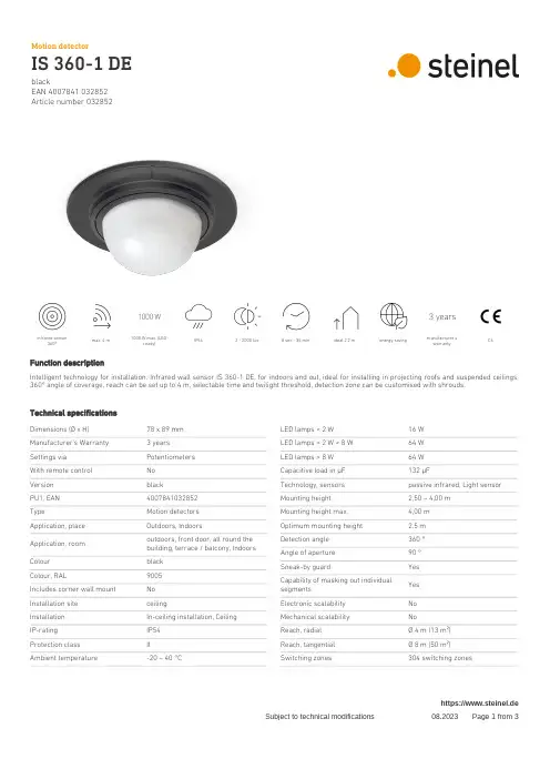
EAN 4007841 032852Article number 032852infrared sensor360°max. 4 m1000 W max. (LED-ready)IP54 2 - 2000 lux 8 sec - 35 min ideal 2,2 m energy savingmanufacturer's warrantyCEFunction descriptionIntelligent technology for installation. Infrared wall sensor IS 360-1 DE, for indoors and out, ideal for installing in projecting roofs and suspended ceilings, 360° angle of coverage, reach can be set up to 4 m, selectable time and twilight threshold, detection zone can be customised with shrouds.Technical specificationsDimensions (Ø x H)78 x 89 mm Manufacturer's Warranty 3 years Settings via Potentiometers With remote control No Version blackPU1, EAN 4007841032852TypeMotion detectors Application, place Outdoors, IndoorsApplication, room outdoors, front door, all round the building, terrace / balcony, Indoors Colour black Colour, RAL9005Includes corner wall mount No Installation site ceilingInstallation In-ceiling installation, Ceiling IP-rating IP54Protection class IIAmbient temperature-20 – 40 °CLED lamps < 2 W 16 W LED lamps > 2 W < 8 W 64 W LED lamps > 8 W 64 W Capacitive load in μF 132 µFTechnology, sensors passive infrared, Light sensor Mounting height 2,50 – 4,00 m Mounting height max.4,00 m Optimum mounting height 2,5 m Detection angle 360 °Angle of aperture 90 °Sneak-by guardYes Capability of masking out individual segmentsYes Electronic scalability No Mechanical scalability NoReach, radial Ø 4 m (13 m²)Reach, tangential Ø 8 m (50 m²)Switching zones304 switching zoneshttps://www.steinel.deEAN 4007841 032852Article number 032852Technical specificationsMaterial PlasticMains power supply230 – 240 V / 50 – 60 Hz Switching output 1, resistive1000 WSwitching output 1, number ofLEDs / fluorescent lamps6 pcs.Fluorescent lamps, electronic ballast430 WFluorescent lamps, uncorrected500 VAFluorescent lamps, series-corrected406 VAFluorescent lamps, parallel-corrected406 VASwitching output 1, low-voltage halogen lamps 1000 VATwilight setting 2 – 2000 lxTime setting8 s – 35 Min.Basic light level function NoMain light adjustable NoTwilight setting TEACH NoConstant-lighting control NoInterconnection YesType of interconnection Master/masterInterconnection via Cablehttps://www.steinel.deEAN 4007841 032852Article number 032852Detection Zone Dimension DrawingLight without neutral conductor Light with neutral conductorConnection using two-circuit switch for manual and automatic operation Circuit diagram Connection via a changeover switch for continuous and automatic operationhttps://www.steinel.de。
米朗科技电涡流位移传感器说明书
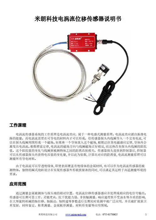
电涡流传感器系统的工作原理是电涡流效应,属于一种电感式测量原理。
电涡流效应源自振荡电路的能量。
而电涡流需要在可导电的材料内才可以形成。
给传感器探头内线圈导入一个交变电流以在探头线圈周围形成一个磁场。
如果将一个导体放入这个磁场,根据法拉第电磁感应定律激发出电涡流。
根据楞兹定律,电涡流的磁场方向与线圈磁场正好相反,而这将改变探头内线圈的阻抗性能参数测量量程1mm 2mm 4mm 5mm 12.5mm 20mm 25mm 50mm探头直径Φ6mm Φ8mm Φ11mm Φ17mm Φ30mm Φ40mm Φ50mm Φ60mm线性误差≤±0.25 ≤±0.25 ≤±0.5 ≤±0.5 ≤±1 ≤±1 ≤±1 ≤±2 (%FS)分辨率0.05um 0.1um 0.2um 0.25um 0.625um 1.0um 1.25um 2.5um重复性0.1um 0.2um 0.4um 0.5um 1.25um 2.0um 2.5um 5um频率响应0~10KHz 0~8KHz 0~2KHz 0~1KHz (-3dB)输出信号0~5V,0~10V,4~20mA,RS485电压型+9~18VDC,+18~36VDC或±15V~±18VDC可选供电电压电流型+22~30VDC,RS485型+12VDC电压型<45mA工作电流电流型<25mARS485型<40mA纹波≤20mV系统温漂≤0.05%/℃静态灵敏度根据输出信号和对应量程而定电压输出:负载能力<10KΩ输出负载电流输出:负载能力<500Ω标定时(20±5)℃环境温度探头-30℃~+150℃使用温度前置器-30℃~+85℃探头 IP67防护等级前置器 IP65探头电缆默认2m,可定制电源电缆默认2m,可定制接线定义电流型电压型RS485 棕线电源正 +24VDC 电源正 +12VDC或+24VDC 电源正 +12VDC黑线空电源负 0V 电源负 0V蓝线电流输出 OUT 输出正 OUT+ RS485 A+白线空输出负 OUT- RS485 B-屏蔽线接大地 GND 接大地 GND 接大地 GND探头典型结构图示在制作过程中,探头头部体一般采用耐高温ABS+PC工程塑料,通过“二次注塑”成型将线圈密封其中。
美国电能Eaton公司产品说明书:Eaton Moeller系列Rapid Link-速控器
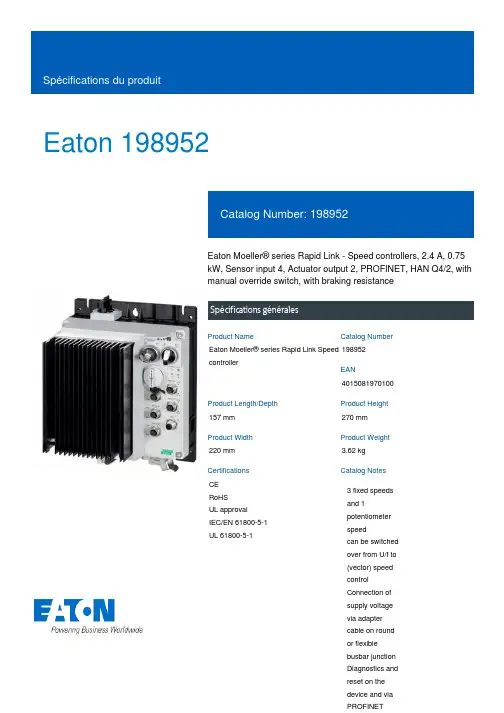
Eaton 198952Eaton Moeller® series Rapid Link - Speed controllers, 2.4 A, 0.75 kW, Sensor input 4, Actuator output 2, PROFINET, HAN Q4/2, with manual override switch, with braking resistanceSpécifications généralesEaton Moeller® series Rapid Link Speed controller1989524015081970100157 mm 270 mm 220 mm 3.62 kg CE RoHS UL approval IEC/EN 61800-5-1 UL 61800-5-1Product NameCatalog NumberEANProduct Length/Depth Product Height Product Width Product Weight Certifications Catalog Notes 3 fixed speeds and 1 potentiometer speedcan be switched over from U/f to (vector) speed control Connection of supply voltage via adapter cable on round or flexible busbar junction Diagnostics and reset on the device and via PROFINET480 VIs the panel builder's responsibility. The specifications for the switchgear must be observed.400 V AC, 3-phase480 V AC, 3-phaseMeets the product standard's requirements.0.75 kW500 VMeets the product standard's requirements.-40 °C380 VKey switch position HANDControl unitIGBT inverterKey switch position OFF/RESETSelector switch (Positions: REV - OFF - FWD)Thermo-click with safe isolationInternal DC linkPTC thermistor monitoringPC connectionManual override switchKey switch position AUTOTwo sensor inputs through M12 sockets (max. 150 mA) for quick stop and interlocked manual operation2 Actuator outputsBreaking resistanceBraking resistance0 Hz Rapid Link 5 - brochureDA-SW-drivesConnect - installation helpDA-SW-drivesConnectDA-SW-drivesConnect - InstallationshilfeDA-SW-USB Driver PC Cable DX-CBL-PC-1M5DA-SW-Driver DX-CBL-PC-3M0DA-SW-USB Driver DX-COM-STICK3-KITMaterial handling applications - airports, warehouses and intra-logistics ETN.RASP5-2420PNT-412R100S1.edzIL034093ZUrasp5_v31.stpramo5_v31.dwgGeneration change RAMO4 to RAMO5Generation change from RA-SP to RASP 4.0Generation change from RA-MO to RAMO 4.0Generation Change RASP4 to RASP5Configuration to Rockwell PLC for Rapid LinkGeneration Change RA-SP to RASP5DA-DC-00004508.pdfDA-DC-00004184.pdfDA-DC-00004514.pdfDA-DC-00003964.pdfeaton-bus-adapter-rapidlink-speed-controller-dimensions-003.eps eaton-bus-adapter-rapidlink-speed-controller-dimensions-004.eps eaton-bus-adapter-rapidlink-speed-controller-dimensions-002.eps eaton-bus-adapter-rapidlink-speed-controller-dimensions-005.epsMains voltage - max10.11 Short-circuit ratingRated operational voltage10.4 Clearances and creepage distancesOutput at quadratic load at rated output voltage - max Output voltage - max10.2.3.1 Verification of thermal stability of enclosures Ambient storage temperature - minMains voltage - minFitted with:Output frequency - min BrochureseCAD model Instructions d'installation mCAD modelNotes sur les applications Rapports de certification SchémasStarting current - max200 %, IH, max. starting current (High Overload), For 2 seconds every 20 seconds, Power sectionRated conditional short-circuit current (Iq)10 kAAmbient operating temperature - max40 °CCommunication interfacePROFINET, optionalAssigned motor power at 115/120 V, 60 Hz, 1-phase1 HPOutput frequency - max500 HzSwitching frequency8 kHz, 4 - 32 kHz adjustable, fPWM, Power section, Main circuitFeaturesParameterization: KeypadParameterization: FieldbusParameterization: drivesConnectParameterization: drivesConnect mobile (App)Ambient operating temperature - min-10 °CBraking current≤ 0.6 A (max. 6 A for 120 ms), Actuator for external motor brakeNumber of HW-interfaces (serial TTY)10.6 Incorporation of switching devices and componentsDoes not apply, since the entire switchgear needs to be evaluated.Nominal output current I2N2.4 A10.2.6 Mechanical impactDoes not apply, since the entire switchgear needs to be evaluated.10.3 Degree of protection of assembliesDoes not apply, since the entire switchgear needs to be evaluated.Product categorySpeed controllerRadio interference classC2, C3: depending on the motor cable length, the connected load, and ambient conditions. External radio interference suppression filters (optional) may be necessary.C1: for conducted emissions onlyHeat dissipation capacity Pdiss0 WRated control voltage (Uc)24 V DC (-15 %/+20 %, external via AS-Interface® plug)Assigned motor power at 460/480 V, 60 Hz, 3-phase1 HPNumber of HW-interfaces (RS-422)Mains current distortion120 %ProtocolPROFINET IO10.9.2 Power-frequency electric strengthIs the panel builder's responsibility.Overvoltage categoryIIIDegree of protectionIP65NEMA 12Ambient storage temperature - max70 °CRated impulse withstand voltage (Uimp)2000 VConnectionPlug type: HAN Q4/2Overload currentAt 40 °CFor 60 s every 600 sFunctions4-quadrant operation possibleBrake chopper with braking resistance for dynamic braking 1 potentiometer speed3 fixed speedsOutput at linear load at rated output voltage - max0.75 kWMains voltage tolerance380 - 480 V (-10 %/+10 %, at 50/60 Hz)Leakage current at ground IPE - max3.5 mAConverter typeU converter10.2.2 Corrosion resistanceMeets the product standard's requirements.Supply frequency50/60 Hz10.2.4 Resistance to ultra-violet (UV) radiationMeets the product standard's requirements.10.2.7 InscriptionsMeets the product standard's requirements.Shock resistance15 g, Mechanical, According to IEC/EN 60068-2-27, 11 ms, Half-sinusoidal shock 11 ms, 1000 shocks per shaftApplication in domestic and commercial area permittedYesNumber of inputs (analog)Number of phases (output)310.12 Electromagnetic compatibilityIs the panel builder's responsibility. The specifications for the switchgear must be observed.10.2.5 LiftingDoes not apply, since the entire switchgear needs to be evaluated.Number of HW-interfaces (RS-485)1Number of HW-interfaces (industrial ethernet)Efficiency97 % (η)System configuration typeCenter-point earthed star network (TN-S network)AC voltagePhase-earthed AC supply systems are not permitted.10.8 Connections for external conductorsIs the panel builder's responsibility.Switch-on threshold for the braking transistor765 VDCProtectionFinger and back-of-hand proof, Protection against direct contact (BGV A3, VBG4)Application in industrial area permittedYesClimatic proofingIn accordance with IEC/EN 50178< 95 %, no condensation10.9.3 Impulse withstand voltageIs the panel builder's responsibility.Overload current IL at 150% overload3.6 AInput current ILN at 150% overload2.5 ANumber of HW-interfaces (RS-232)Number of inputs (digital)4Current limitation0.2 - 2.4 A, motor, main circuitAdjustable, motor, main circuitCable lengthC3 ≤ 25 m, maximum motor cable lengthC2 ≤ 5 m, maximum motor cable lengthC1 ≤ 1 m, maximum motor cable length10.5 Protection against electric shockDoes not apply, since the entire switchgear needs to be evaluated.Mounting positionVerticalMains switch-on frequencyMaximum of one time every 60 seconds10.13 Mechanical functionThe device meets the requirements, provided the information in the instruction leaflet (IL) is observed.10.9.4 Testing of enclosures made of insulating materialIs the panel builder's responsibility.Heat dissipation per pole, current-dependent Pvid0 WElectromagnetic compatibility1st and 2nd environments (according to EN 61800-3)Resolution0.1 Hz (Frequency resolution, setpoint value)Assigned motor power at 460/480 V, 60 Hz1 HPRelative symmetric net voltage tolerance10 %Rated operational current (Ie)2.4 A at 150% overload (at an operating frequency of 8 kHz and an ambient air temperature of +40 °C)Number of outputs (analog)Rated operational power at 380/400 V, 50 Hz, 3-phase0.75 kWNumber of HW-interfaces (USB)Operating modePM and LSPM motorsSynchronous reluctance motorsU/f controlSensorless vector control (SLV)BLDC motorsRated frequency - min45 HzDelay time< 10 ms, Off-delay< 10 ms, On-delayNumber of outputs (digital)2Power consumption32 W10.2.3.2 Verification of resistance of insulating materials to normal heatMeets the product standard's requirements.10.2.3.3 Resist. of insul. mat. to abnormal heat/fire by internal elect. effectsMeets the product standard's requirements.Number of HW-interfaces (other)Rated frequency - max66 HzVibrationResistance: 10 - 150 Hz, Oscillation frequencyResistance: 6 Hz, Amplitude 0.15 mmResistance: 57 Hz, Amplitude transition frequency on accelerationResistance: According to IEC/EN 60068-2-6Short-circuit protection (external output circuits)Type 1 coordination via the power bus' feeder unit, Main circuit10.7 Internal electrical circuits and connectionsIs the panel builder's responsibility.Braking torqueAdjustable to 100 % (I/Ie), DC - Main circuitRelative symmetric net frequency tolerance10 %10.10 Temperature riseThe panel builder is responsible for the temperature rise calculation. Eaton will provide heat dissipation data for the devices.Number of HW-interfaces (parallel)Assigned motor power at 230/240 V, 60 Hz, 1-phase1 HPInterfacesMax. total power consumption from AS-Interface® power supply unit (30 V): 250 mASpecification: S-7.4 (AS-Interface®)Number of slave addresses: 31 (AS-Interface®)Number of phases (input)Eaton Corporation plc Eaton House30 Pembroke Road Dublin 4, Ireland © 2023 Eaton. Tous droits réservés.Eaton is a registered trademark.All other trademarks are property of their respectiveowners./socialmedia327.5 W at 50% current and 90% speed 31.8 W at 100% current and 90% speed 33.5 W at 25% current and 50% speed 34.6 W at 50% current and 50% speed 35.1 W at 25% current and 0% speed 36.6 W at 100% current and 50% speed 36.8 W at 50% current and 0% speed 40.7 W at 100% current and 0% speed 2Max. 2000 mAbove 1000 m with 1 % performance reduction per 100 mHeat dissipation at current/speed Number of interfaces (PROFINET)Altitude。
奥美晨曦系列微波传感器说明书
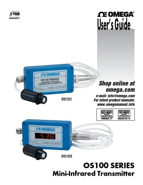
OS100 SERIES Mini-Infrared Transmitter e-mail:**************For latest product manuals: Shop online at User’s G ui d e***********************Servicing North America:U.S.A. Omega Engineering, Inc.Headquarters: Toll-Free: 1-800-826-6342 (USA & Canada only)Customer Service: 1-800-622-2378 (USA & Canada only)Engineering Service: 1-800-872-9436 (USA & Canada only)Tel: (203) 359-1660 Fax: (203) 359-7700e-mail:**************For Other Locations Visit /worldwideThe information contained in this document is believed to be correct, but OMEGA accepts no liability for any errors it contains, and reserves the right to alter specifications without notice.Table of ContentsSection ...................................................................PageSafety Warnings and IEC Symbols (iii)Caution and Safety Information (iii)Section 1 Introduction ....................................................................1-1Section 2Installation ......................................................................1-12.1 Unpacking and Inspection ......................................1-12.2 Electrical Connection ..............................................2-1Section 3Operation ........................................................................3-13.1 Main Board ................................................................3-13.2 Ambient Temperature ..............................................3-23.3 Atmospheric Quality ................................................3-33.4 Measuring Temperature ..........................................3-33.5 Alarm Setting ............................................................3-43.6 Adding Extension Cable...........................................3-4Section 4 Laser Sight Accessory ...................................................4-14.1 Warning and Cautions .............................................4-14.2 Operating the Laser Sight Accessory .....................4-1Section 5 Specifications .................................................................5-15.1 General .......................................................................5-15.2 Laser Sight Accessory (OS100-LS) ..........................5-2Section 6Emissivity Table .............................................................6-1iTable of FiguresFigure Description Page2-1Power Supply & Analog Output Connections ..........2-12-2 Alarm Output Connection ............................................2-13-1 Main PC Board ...............................................................3-23-2 Sensor..............................................................3-2Housing3-3 Optical Field of View .....................................................3-43-4Setting the Temperature Engineering Unit..................3-43-5Mounting Bracket OS100-MB .......................................3-53-6Water Cooling Jacket, OS100-WC ................................3-53-7Typical Water Cool Jacket Assembly ...........................3-53-8Air Purge Collar, OS100-AP..........................................3-63-9DIN Rail Mounting Adapter, OS100-DR ....................3-63-10NEMA-4 Aluminum Enclosure ....................................3-64-1Laser Sighting Accessory, OS100-LS ............................4-24-2Laser Warning Label ......................................................4-2iiSafety Warnings and IEC SymbolsThis device is marked with international safety and hazard symbols in accordance with IEC 1010. It is important to read and follow all precautions and instructions in this manual before operating or commissioning this device as it contains important information relating to safety and EMC. Failure to follow all safety precautions may result in injury and or damage to your calibrator. IEC symbols DescriptionCaution and Safety Information• If the equipment is used in a manner not specified in this manual, the protection provided by the equipment may be impaired.• The installation category is one (1).• There are no user replaceable fuses in this product• The output terminals of this product are for use with equipment (digital meters, chart recorders, etc,) which have no accessible five parts. Such equipment should comply with all the applicable safety requirements.• Do not operate the equipment in flammable or explosive environments.• All connections to the thermometer should be made via a shielded cable, 24 AWG stranded wire with the following ratings: 300V , 105°C (221°F), PVC insulation.• Power must be disconnected before making any electrical connections.• The power supply used to power the thermometer should be VDE or UL approved with the following ratings: 12 to 24vdc @150mA with overload protection of 500mA.iiiCaution, refer to accompanying documentsDirect Current Laser SymbolFrame or ChassisNOTES: ivSection 1 - IntroductionThe low cost OS101 mini-infrared transmitter provides non-contacttemperature measurement for industrial applications. The unit measures atemperature range of -18 to 538°C (0-1000°F) and provides a linear analogoutput of either 4-20 mA, 0-5 VDC, K type TC, 1 mV/°C, or 1 mV/°F.The new OS102 mini-infrared transmitter has all the functions of OS101plus a built-in LED display that shows the measured temperature indegrees F or degrees C which is switchable in the field.The miniature sensor head design 2.5 cm dia. x 6.3 cm Length (1" x 2.5") isideal for measuring temperature in confined, and hard to reach places.The aluminum sensor head as well as the rugged electronic housing (Diecast Aluminum) are NEMA-4 rated.The sensor head is connected to the electronic housing via a 1.82 m (6 feet)shielded cable as standard. The unit provides field adjustable alarmoutput.Section 2 - Installation2.1UnpackingRemove the packing list and verify that you have received all yourequipment. If you have any questions about the shipment, please callCustomer Service at:1-800-622-2378 or 203-359-1660. We can also be reached on the internet:e-mail:**************When you receive the shipment, inspect the container and equipment forany signs of damage. Note any evidence of rough handling in transit.inspection. After examination and removing contents, save packing material and carton in theevent reshipment is necessary.The following items are supplied in the box:• The infrared transmitter including the sensor head and the 1.82 m(6 feet) shielded cable• User's Manual• Mounting Nut1-1The following describes the ordering information:OS102 or OS101 - MA- *,**, where The following optional accessories are available:Here are the Features of OS101 and OS102 infrared transmitters:2.2Electrical Connection Sensor Head Cable - The Sensor head is pre-wired to a 1.8 m (6 feet)shielded cable. Plug & lock-in the male connector to the mating female connector on the aluminum housing.Power & Output Connection - Open the cover of the main aluminum housing. Slide the cable through the strain relief and connect the wires to the terminal block on the board as shown in Fig. 2-1. For Alarm output connection, refer to Fig. 2-2.2-1MA - 4/20 mA output V1 - 0 to 5 VDC output K - Thermocouple output, K type MV - Millivolt output C - 1 mV/°C output F - 1 mV/°F output HT- High temperature sensor head3-1Figure 2-2. Alarm Output Connection Section 3 - Operation3-1Main BoardThe Main Board is shown in Fig. 3-1. Here are the important components on the board:(1) - Terminal Block for Power & Output connections(2) - Single Turn Potentiometer to adjust Emissivity in tenths (0.x_)(3) - Single Turn Potentiometer to adjust Emissivity in hundreds (0._x)(4) -Slide switch to select between real time (Normal Operation) and alarm set point(5) - Alarm set point adjust, P4(6) - Sensor Head connection(7) - Input Zero adjust, P3(8) - Input Span adjust, P2(9) - Output Zero adjust, P5(10) - Output Span adjust, P6Figure 3-1. Main PC Board3.2Ambient TemperatureThe Sensing head can operate in an ambient temperature of 0 to 70°C (32to 158°F). The Sensing head in the high temperature model (-HT) can operate in an ambient temperature of 0 to 85°C (32 to 185°F) without any cooling required. The Sensing head can operate up to 200°C (392°F) using the water cool jacket accessory OS100-WC (See Fig. 3-6).There is a warm up period of 3 minutes after power up. After the warm up period, temperature measurement can be made.When the ambient temperature around the sensor head changes abruptly,the sensor head goes through thermal shock. It takes a certain amount of time for the sensor head to stabilize to the new ambient temperature. For example, it takes about 30 minutes for the sensor head to stabilize going from 25°C to 50°C (77 to 122°F) ambient temperature.The sensor head dimensions are shown in Fig. 3-2.Figure 3-2. Sensor Housing3-23-33.3Atmospheric QualityEnvironments with smoke, dust, and fumes dirty up the optical lens, and cause erroneous temperature readings. To keep the surface of the optical lens clean, the air purge collar accessory is recommended, OS100-AP , See Fig. 3-7.3.4Measuring TemperatureBefore starting to measure temperature, make sure that the following check list is met:ߜ The power and analog output connections are made (Fig. 2-1).ߜThe sensor head is connected to the main unit.ߜThe slide switch (SW1) on the main board is set to real time (Fig. 3-1).ߜThe target is larger than the optical field of view of the sensor head (Fig. 3-3).ߜThe emissivity adjustment on the main board is set properly (Fig. 3-1).ߜThe output load is within the product specification.On OS102 transmitters, follow these additional steps:ߜ The temperature display is set to °F or °C (Fig. 3-4)ߜ For 4-20mA output models, make sure an output load is added, ie. 250ohms.Figure 3-3. Optical Field Of ViewFigure 3-4. Setting the Temperature Engineering Unit3.5Alarm SettingThe unit provides 0-100% alarm set point adjustment. Here is an exampleof an alarm setting.• An OS101-MA(4/20 mA output), the alarm is to be set at 400°Ftemperature.• Connect the alarm output as shown in Fig. 2-2.• Set the slide switch (SW1) on the main board to the Alarm position.• Measure the analog output, and set the Potentiometer P4 until theoutput reads 10.4 mA which is 40% (400°F) of the temperature range.40 x (20-4)[10.4mA=+ 4]100• Set the slide switch (SW1) back to the Real Time position.• If the temperature reading is below the alarm set point, the alarmoutput stays high, otherwise it goes low.On the OS102, you can set the alarm set point directly based on thetemperature display.3.6Adding Extension CableYou can add extension cable between the Sensor Head and the mainelectronic housing up to 15.2 m (50 feet). After adding the extension cable,the Zero input potentiometer, P3 may be re-adjusted. (See Fig. 3-1, forproper analog output reading)The following figures show the mounting bracket (OS100-MB), Watercooling jacket (OS100-WC), Air purge collar (OS100-AP), DIN RailMounting adapter (OS-100-DR), and the main aluminum enclosure. TheDIN Rail Mounting adapter (OS100-DR) is mounted to the bottom of themain aluminum enclosure using two 4-40 screws.A typical water cool jacket assembly is shown in Fig. 3-7, on the following page.1. Mounting Nut2. Mounting Bracket3. Water Cool Jacket4. Sensor Head3-4Figure 3-5. Mounting Bracket OS100-MBFigure 3-6. Water Cooling Jacket, OS100-WCFigure 3-7. Typical Water Cool Jacket Assembly3-5Figure 3-8. Air Purge Collar, OS100-APFigure 3-9. DIN Rail Mounting Adapter, OS-100-DRFigure 3-10. NEMA-4 Aluminum Enclosure3-6Section 4 - Laser Sight Accessory4.1Warning and Cautionsbelow:•Use of controls or adjustments or performance of procedures other than those specified here may result in hazardous radiation exposure.• Do not look at the laser beam coming out of the lens or view directly with optical instruments - eye damage can result.• Use extreme caution when operation the laser sight accessory • Never point the laser accessory at a person • Keep out of the reach of all children4.2Operating the Laser Sight AccessoryThe laser sight accessory screws onto the front of the sensor head. This accessory is only used for alignment of the sensor head to the target area.After the alignment process, the accessory has to be removed from the front of the sensor head before temperature measurement.The laser sight accessory is powered from a small compact battery pack (included with the accessory). Connect the battery pack to the accessory using the cable provided. Aim at the target, and turn on the battery power using the slide switch on the battery pack. Adjust the sensor head position so that the laser beam points to the center of the target area. Turn off the battery pack, and remove the laser sighting accessory from the sensor head. See Fig. 4-1 for reference.4-14-2Figure 4-2. Laser Warning LabelSection 5 - Specifications5.1 - GeneralTemperature Range-18 to 538°C (0 to 1000°F)Accuracy @ 22°C (72°F)±2% of Rdg. or 2.2°C (4°F) whichever is ambient temperature & greateremissivity of 0.95 or greaterOptical Field of View6:1 (Distance/Spot Size)Repeatability±1% of Rdg.Spectral Response 5 to 14 micronsResponse Time150 msec (0 to 63% of final value)Emissivity Range0.1 to 0.99, adjustableOperating Ambient TemperatureMain Transmitter0 to 50°C (32 to 122°F)Sensor Head0 to 70°C (32 to 158°F)Sensor Head (-HT Model)0 to 85°C (32 to 185°F)Sensor Head with OS100-WC(Water Cooling Jacket)0 to 200°C (32 to 392°F)Operating Relative Humidity Less than 95% RH, non-condensingWater Flow Rate for OS100-WC0.25 GPM, room temperatureThermal Shock About 30 minutes for 25°Cabrupt ambient temperature change Warm Up Period 3 minutesAir Flow Rate for OS100-AP 1 CFM (0.5 Liters/sec.)Power12 to 24 VDC @ 100 mAAnalog OutputsMV-F 1 mV/°FMV-C 1 mV/°CK K Type TC - OS101 onlyMA 4 to 20 mAV10 to 5 VDCOutput Load requirementsMin. Load (0 to 5VDC) 1 K-OhmsMax. Load (4 to 20 mA)(Supply Power - 4 )/20 mATransmitter Housing NEMA-4 & IP65, Die Cast AluminumSensor Head Housing NEMA-4 , AluminumAlarm Output Open Drain, 100 mAAlarm Set Point0 to 100% , Adjustable via P4Alarm Deadband14°C (25°F)5-15-25.1 - General Con’t.DimensionsSensor Head25.4 OD. x 63.5 mm L(1" OD. x 2.5" L)Main Housing, OS10165.5 W x 30.5 H x 115.3 mm L(2.58" W x 1.2" H x 4.54" L)Main Housing, OS10265.5 W x 55.9 H x 115.3 mm L(2.58" W x 2.2" H x 4.54" L)Weight 272 g (0.6 lb)5.2Laser Sight Accessory (OS100-LS)Wavelength (Color)630 - 670 nm (Red)Operating Distance (Laser Dot)Up to 9.1 m (30 ft.)Max. Output Optical Power Less than 1 mW at 22°F ambienttemperature.European Classification Class 2, EN60825-1/11.2001Maximum Operating current45 mA at 3 VDCFDA Classification Complies with 21 CFR 1040.10,Class II Laser ProductBeam Diameter 5 mmBeam Divergence< 2 mradOperating Temperature0 to 50°C (32 to 122°F)Operating Relative Humidity Less than 95% RH, non-condensingPower Switch ON / OFF , Slide switch on the BatteryPackPower Indicator Red LEDPower Battery Pack, 3 VDC (Consists of two 1.5VDC AA size Lithium Batteries) Laser Warning Label Located on the head sight circumferenceIdentification Label Located on the head sight circumferenceDimensions38 DIA x 50.8 mm L(1.5" DIA x 2" L)Section 6 - Emissivity Table6-1Material Emissivity (ε)Aluminum – pure highly polished plate . . . . . . . . . . . . . . . . . . . . . . . . 0.04 to 0.06Aluminum – heavily oxidized . . . . . . . . . . . . . . . . . . . . . . . . . . . . . . . 0.20 to 0.31Aluminum – commercial sheet . . . . . . . . . . . . . . . . . . . . . . . . . . . . . . . . . . . . 0.09Brass – dull plate. . . . . . . . . . . . . . . . . . . . . . . . . . . . . . . . . . . . . . . . . . . . . . 0.22Brass – highly polished, 73.2% Cu, 26.7% Zn. . . . . . . . . . . . . . . . . . . . . . . . . 0.03Chromium – polished. . . . . . . . . . . . . . . . . . . . . . . . . . . . . . . . . . . . . 0.08 to 0.36Copper – polished. . . . . . . . . . . . . . . . . . . . . . . . . . . . . . . . . . . . . . . . . . . . . 0.05Copper – heated at 600°C (1112°F). . . . . . . . . . . . . . . . . . . . . . . . . . . . . . . 0.57Gold – pure, highly polished or liquid. . . . . . . . . . . . . . . . . . . . . . . . . 0.02 to 0.04Iron and steel (excluding stainless)– polished iron . . . . . . . . . . . . . . . . 0.14 to 0.38Iron and steel (excluding stainless)– polished cast iron. . . . . . . . . . . . . . . . . . . 0.21Iron and steel (excluding stainless)– polished wrought iron . . . . . . . . . . . . . . . 0.28Iron and steel (excluding stainless)– oxidized dull wrought iron . . . . . . . . . . . . 0.94Iron and steel (excluding stainless)– rusted iron plate . . . . . . . . . . . . . . . . . . . 0.69Iron and steel (excluding stainless)– polished steel. . . . . . . . . . . . . . . . . . . . . . 0.07Iron and steel (excluding stainless)– polished steel oxidized at600°C (1112°F). . . . . . . . . . . . . . . . . . . . 0.79Iron and steel (excluding stainless)– rolled sheet steel . . . . . . . . . . . . . . . . . . . 0.66Iron and steel (excluding stainless)– rough steel plate . . . . . . . . . . . . . 0.94 to 0.97Lead – gray and oxidized . . . . . . . . . . . . . . . . . . . . . . . . . . . . . . . . . . . . . . . 0.28Mercury . . . . . . . . . . . . . . . . . . . . . . . . . . . . . . . . . . . . . . . . . . . . . 0.09 to 0.12Molybdenum filament . . . . . . . . . . . . . . . . . . . . . . . . . . . . . . . . . . . . 0.10 to 0.20Nickel – polished . . . . . . . . . . . . . . . . . . . . . . . . . . . . . . . . . . . . . . . . . . . . . 0.07Nickel – oxidized at 649 to 1254°C (1200°F to 2290°F). . . . . . . . . . . 0.59 to 0.86Platinum – pure polished plate . . . . . . . . . . . . . . . . . . . . . . . . . . . . . . 0.05 to 0.10Platinum – wire . . . . . . . . . . . . . . . . . . . . . . . . . . . . . . . . . . . . . . . . 0.07 to 0.18Silver – pure and polished . . . . . . . . . . . . . . . . . . . . . . . . . . . . . . . . . 0.02 to 0.03Stainless steel – polished . . . . . . . . . . . . . . . . . . . . . . . . . . . . . . . . . . . . . . . . 0.07Stainless steel – Type 301 at 232 to 942°C (450°F to 1725°F). . . . . . . 0.54 to 0.63Tin – bright . . . . . . . . . . . . . . . . . . . . . . . . . . . . . . . . . . . . . . . . . . . . . . . . . 0.06Tungsten – filament . . . . . . . . . . . . . . . . . . . . . . . . . . . . . . . . . . . . . . . . . . . . 0.39Zinc – polished commercial pure . . . . . . . . . . . . . . . . . . . . . . . . . . . . . . . . . . 0.05Zinc – galvanized sheet. . . . . . . . . . . . . . . . . . . . . . . . . . . . . . . . . . . . . . . . . 0.23M E T A L S6-2Material Emissivity (ε) Asbestos Board . . . . . . . . . . . . . . . . . . . . . . . . . . . . . . . . . . . . . . . . . . . . . . .0.96 Asphalt, tar, pitch . . . . . . . . . . . . . . . . . . . . . . . . . . . . . . . . . . . . . . .0.95 to 1.00 Brick– red and rough . . . . . . . . . . . . . . . . . . . . . . . . . . . . . . . . . . . . . . . . . .0.93 Brick– fireclay . . . . . . . . . . . . . . . . . . . . . . . . . . . . . . . . . . . . . . . . . . . . . . .0.75 Carbon– filament . . . . . . . . . . . . . . . . . . . . . . . . . . . . . . . . . . . . . . . . . . . . .0.53 Carbon– lampblack - rough deposit . . . . . . . . . . . . . . . . . . . . . . . . . .0.78 to 0.84 Glass- Pyrex, lead, soda . . . . . . . . . . . . . . . . . . . . . . . . . . . . . . . . . .0.85 to 0.95 Marble– polished light gray . . . . . . . . . . . . . . . . . . . . . . . . . . . . . . . . . . . . .0.93 Paints, lacquers, and varnishes– Black matte shellac . . . . . . . . . . . . . . . . . . . .0.91 Paints, lacquers, and varnishes– aluminum paints . . . . . . . . . . . . . . . .0.27 to 0.67 Paints, lacquers, and varnishes– flat black lacquer . . . . . . . . . . . . . . .0.96 to 0.98 Paints, lacquers, and varnishes– white enamel varnish . . . . . . . . . . . . . . . . . .0.91 Porcelain– glazed . . . . . . . . . . . . . . . . . . . . . . . . . . . . . . . . . . . . . . . . . . . . .0.92 Quartz– opaque . . . . . . . . . . . . . . . . . . . . . . . . . . . . . . . . . . . . . . . .0.68 to 0.92 Roofing Paper . . . . . . . . . . . . . . . . . . . . . . . . . . . . . . . . . . . . . . . . . . . . . . .0.91 Tape– Masking . . . . . . . . . . . . . . . . . . . . . . . . . . . . . . . . . . . . . . . . . . . . . .0.95 Water . . . . . . . . . . . . . . . . . . . . . . . . . . . . . . . . . . . . . . . . . . . . . . . .0.95 to 0.96 Wood– planed oak . . . . . . . . . . . . . . . . . . . . . . . . . . . . . . . . . . . . . . . . . . . .0.90 NONMETALSNOTES:6-3NOTES: 6-4OMEGA’s policy is to make running changes, not model changes, whenever an improvement is possible. T his affords our customers the latest in technology and engineering.OMEGA is a trademark of OMEGA ENGINEERING, INC.© Copyright 2017 OMEGA ENGINEERING, INC. All rights reserved. T his document may not be copied, photocopied, reproduced, translated, or reduced to any electronic medium or machine-readable form, in whole or in part, without the prior written consent of OMEGA ENGINEERING, INC.FOR WARRANTY RETURNS, please have the following information available BEFORE contacting OMEGA:1. P urchase Order number under which the product was PURCHASED,2. M odel and serial number of the product under warranty, and3. Repair instructions and/or specific problems relative to the product.FOR NON-WARRANTY REPAIRS, consult OMEGA for current repair charges. Have the following information available BEFORE contacting OMEGA:1. Purchase Order number to cover the COST of the repair,2. Model and serial number of the product, and 3. Repair instructions and/or specific problems relative to the product.RETURN REQUESTS/INQUIRIESDirect all warranty and repair requests/inquiries to the OMEGA Customer Service Department. BEFORE RET URNING ANY PRODUCT (S) T O OMEGA, PURCHASER MUST OBT AIN AN AUT HORIZED RET URN (AR) NUMBER FROM OMEGA’S CUST OMER SERVICE DEPART MENT (IN ORDER T O AVOID PROCESSING DELAYS). The assigned AR number should then be marked on the outside of the return package and on any correspondence.T he purchaser is responsible for shipping charges, freight, insurance and proper packaging to preventbreakage in transit.WARRANTY/DISCLAIMEROMEGA ENGINEERING, INC. warrants this unit to be free of defects in materials and workmanship for a period of 25 months from date of purchase. OMEGA’s WARRANTY adds an additional one (1) month grace period to the normal two (2) year product warranty to cover handling and shipping time. This ensures that OMEGA’s customers receive maximum coverage on each product.If the unit malfunctions, it must be returned to the factory for evaluation. OMEGA’s Customer Service Department will issue an Authorized Return (AR) number immediately upon phone or written request. Upon examination by OMEGA, if the unit is found to be defective, it will be repaired or replaced at no charge. OMEGA’s WARRANT Y does not apply to defects resulting from any action of the purchaser, including but not limited to mishandling, improper interfacing, operation outside of design limits, improper repair, or unauthorized modification. T his WARRANT Y is VOID if the unit shows evidence of having been tampered with or shows evidence of having been damaged as a result of excessive corrosion; or current, heat, moisture or vibration; improper specification; misapplication; misuse or other operating conditions outside of OMEGA’s control. Components in which wear is not warranted, include but are not limited to contact points, fuses, and triacs.OMEGA is pleased to offer suggestions on the use of its various products. However, OMEGA neither assumes responsibility for any omissions or errors nor assumes liability for any damages that result from the use of its products in accordance with information provided by OMEGA, either verbal or written. OMEGA warrants only that the parts manufactured by the company will be as specified and free of defects. OMEGA MAKES NO OTHER WARRANTIES OR REPRESENTATIONS OF ANY KIND WHATSOEVER, EXPRESSED OR IMPLIED, EXCEPT THAT OF TITLE, AND ALL IMPLIED W ARRANTIES INCLUDING ANY W ARRANTY OF MERCHANTABILITY AND FITNESS FOR A PARTICULAR PURPOSE ARE HEREBY DISCLAIMED. LIMITATION OF LIABILITY: The remedies of purchaser set forth herein are exclusive, and the total liability of OMEGA with respect to this order, whether based on contract, warranty, negligence, indemnification, strict liability or otherwise, shall not exceed the purchase price of the component upon which liability is based. In no event shall OMEGA be liable for consequential, incidental or special damages.CONDITIONS: Equipment sold by OMEGA is not intended to be used, nor shall it be used: (1) as a “Basic Component” under 10 CFR 21 (NRC), used in or with any nuclear installation or activity; or (2) in medical applications or used on humans. Should any Product(s) be used in or with any nuclear installation or activity, medical application, used on humans, or misused in any way, OMEGA assumes no responsibility as set forth in our basic WARRANT Y /DISCLAIMER language, and, additionally, purchaser will indemnify OMEGA and hold OMEGA harmless from any liability or damage whatsoever arising out of the use of theProduct(s) in such a manner.Where Do I Find Everything I Need forProcess Measurement and Control?OMEGA…Of Course!Shop online at TEMPERATUREM U Thermocouple, RTD & Thermistor Probes, Connectors,Panels & AssembliesM U Wire: Thermocouple, RTD & ThermistorM U Calibrators & Ice Point ReferencesM U Recorders, Controllers & Process MonitorsM U Infrared PyrometersPRESSURE, STRAIN AND FORCEM U Transducers & Strain GagesM U Load Cells & Pressure GagesM U Displacement TransducersM U Instrumentation & AccessoriesFLOW/LEVELM U Rotameters, Gas Mass Flowmeters & Flow ComputersM U Air Velocity IndicatorsM U Turbine/Paddlewheel SystemsM U Totalizers & Batch ControllerspH/CONDUCTIVITYM U pH Electrodes, Testers & AccessoriesM U Benchtop/Laboratory MetersM U Controllers, Calibrators, Simulators & PumpsM U Industrial pH & Conductivity EquipmentDATA ACQUISITIONM U Communications-Based Acquisition SystemsM U Data Logging SystemsM U Wireless Sensors, Transmitters, & ReceiversM U Signal ConditionersM U Data Acquisition SoftwareHEATERSM U Heating CableM U Cartridge & Strip HeatersM U Immersion & Band HeatersM U Flexible HeatersM U Laboratory HeatersENVIRONMENTALMONITORING AND CONTROLM U Metering & Control InstrumentationM U RefractometersM U Pumps & TubingM U Air, Soil & Water MonitorsM U Industrial Water & Wastewater TreatmentM U pH, Conductivity & Dissolved Oxygen InstrumentsM3572/1217。
靠近感应传感器规格说明说明书
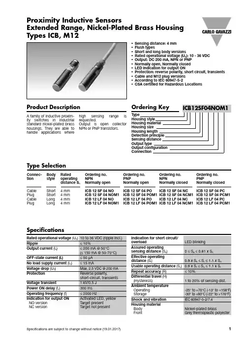
ICB 12 SF 04 PO ICB 12 SF 04 NC ICB 12 SF 04 PC ICB 12 SF 04 POM1 ICB 12 SF 04 NCM1 ICB 12 SF 04 PCM1 ICB 12 LF 04 PO ICB 12 LF 04 NC ICB 12 LF 04 PC ICB 12 LF 04 POM1 ICB 12 LF 04 NCM1 ICB 12 LF 04 PCM1
-25° to +70°C (-13° to +158°F) -30° to +80°C (-22° to +176°F)
Shock and vibration
IEC 60947-5-2/7.4
Housing material Body Front
Nickel-plated brass Grey thermoplastic polyester
Sn : nominal sensing distance d : sensor diameter
d : sensor diameter
For sensors installed opposite each other, a minimum space of 6 x Sn (the nominal sensing distance) must be observed (See Picture 3).
Proximity Inductive Sensors Extended Range, Nickel-Plated Brass Housing Types ICB, M12
• Sensing distance: 4 mm • Flush types • Short and long body versions • Rated operational voltage (Ub): 10 - 36 VDC • Output: DC 200 mA, NPN or PNP • Normally open, Normally closed • LED indication for output ON • Protection: reverse polarity, short circuit, transients • Cable and M12 plug versions • According to IEC 60947-5-2 • CSA certified for Hazardous Locations
可汗6D标2全面传感器相机说明书

VERSATILITY DELIVERED14.9mm35.9mmFull-frame SensorAPS-C Sensor24.0mm22.3mm26.2 Megapixel Full-frame CMOS SensorThe EOS 6D Mark II features a 26.2 effective Megapixel, full-frame CMOS sensor (approx. 35.9mm x 24.0mm) designed to create high-resolution and detailed images as well as take full advantage of Canon’s incredible collection of EF lenses. The EOS 6D Mark II’s sensor delivers an impressive combination of light sensitivity and detail, ideal for high-resolution shooting, and gives the user additional room to crop photos without compromising image quality.DIGIC 7 Image Processor, ISO 100–40000The DIGIC 7 Image Processor accelerates and facilitates all aspects of the EOS 6D Mark II camera’s operation, enhancing image capture with improved resolution, detail and noise reduction. It increases subject tracking speed and accuracy in Live View AF, helping to maintain focus on the subject, and enables a broad range of ISO settings, from 100–40000 (expandable to L: 50 and H2: 102400), for detailed results, even in low light. The DIGIC 7 Image Processor helps the EOS 6D Mark II capture sharp, striking and lifelike photos and videos with incredible speed.Dual Pixel CMOS AF with Touch Screen LCDThe EOS 6D Mark II camera features a 3.0-inch Vari-angle Touch Screen LCD that can be ideal for composing and reviewing your photos and videos. With Dual Pixel CMOS AF, simply tap where the subject is located on the screen during Live View while taking videos or photos, and it will help to quickly focus and track the subject throughout the frame.Outstanding VideoThe EOS 6D Mark II camera makes it easy to capture and share high-quality videos quickly, easily and with virtually no compromise. In bright daylight or at dusk, whatever the speed of the action, the EOS 6D Mark II can help make sharp, beautifully exposed 60p and 4K Time-lapse videos. The camera’s Dual Pixel CMOS AF system focuses fast, and Movie Servo AF tracking helps maintain focus even when the action gets going. The Vari-angle Touch Screen LCD also makes it easy to compose from almost any vantage point. The ability to record as both MOV and MP4 files makes sharing fast and easy.Wireless ConnectivityThe EOS 6D Mark II is equipped with numerous wireless capabilities for any number of shooting and sharing setups. Using Canon’s free Camera Connect App, the EOS 6D Mark II can connect to compatible mobile devices. The camera has built-in Wi-Fi®***, NFC^, Bluetooth®^^ and GPS ^^^capability, enabling wireless remote shooting, image transfer and sharing, geotagging and network connectivity.Compact & Rugged Design, Dust- & Water-resistantThe EOS 6D Mark II is built for uninterrupted performance, even when conditions get messy. The battery compartment cover, card slot cover, lens mount, terminal covers and buttons are weather-sealed to help keep water and dust out. The EOS 6D Mark II’s high precision aluminum alloy and polycarbonate resin construction makes the camera lightweight, durable and capable of shooting a variety of excursions from vacations to photo shoots to a fun day on a hike.45-point All Cross-type AF System *The EOS 6D Mark II camera has a 45-point all cross-type AF system*. It has low luminance performance to EV -3 which makes it excellent in dim light, and it’s compatible with an array of EF lenses (lenses with maximum apertures of f/8 or smaller, and some lenses with extenders attached may operate at a maximum of 27 points). The EOS 6D Mark II also features 5 types of AF area selection modes useful for a number of different AF situations such as fast-paced, still or event environments.High-speed Continuous Shooting at up to 6.5 fps **The EOS 6D Mark II’s remarkable shutter and image processing system helps ensure virtually instantaneous response and performance at up to 6.5 fps** which is great for helping the user capture spontaneous moments like at a wedding or capture action during a sporting event.Cross-type focusing:f/5.6 vertical + f/5.6 horizontal (some also supporting f/8)Dual cross-type focusing:f/2.8 right diagonal + f/2.8 left diagonal f/5.6 vertical + f/5.6 horizontal (also supporting f/8)©Adam Jones/FEATURE6D2Adam Jones1-800-OK-CANON /FEATURE6D2Printed in U.S.A.* The number of AF points, cross-type AF points and Dual cross-type AF points vary depending on the lens used.** Continuous shooting speed may vary depending on the shutter speed, the aperture, the lens being used, the battery charge and various camera settings.*** Compatible with iOS® versions 8.4/9.3/10.2, Android™ smartphone and tablet versions 4.1/4.2/4.3/4.4/5.0/5.1/6.0/7.0/7.1. Data charges may apply with the download of the free Canon Camera Connect app. This app helps enable you to upload images to social media services. Please note that image files may contain personally identifiable information that may implicate privacy laws. Canon disclaims and has no responsibility for your use of such images. Canon does not obtain, collect or use such images or any information included in such images through this app. ^ Compatible with Android™ smartphone and tablet versions 4.1/4.2/4.3/4.4/5.0/5.1/6.0/7.0/7.1.^^ Compatible with select smartphone and tablet devices (Android™ version 5.0 or later and the following iOS® devices: iPhone 4s or later, iPad 3rd gen. or later, iPod Touch 5th gen. or later) equipped with Bluetooth® version 4.0 or later and the Camera Connect App Ver. 2.0.40. This application is not guaranteed to operate on all listed devices, even if minimum requirements are met.^^^ In certain countries and regions, the use of GPS may be restricted. Therefore, be sure to use GPS in accordance with the laws and regulations of your country or region. Be particularly careful when traveling outside your home country. As a signal is received from GPS satellites, take sufficient measures when using in locations where the use of electronics is regulated.Not responsible for typographical errors. Certain images and effects are simulated. Products not shown to scale.Maximum FlashSynchronization Speed 1/180 sec.; EX-series SpeedlitesMetering System63-zone TTL open-aperture metering1. Evaluative metering (linked to all AF points)2. Partial metering (center, approx. 6.5 % of viewfinder)3. Spot metering (center, approx. 3.2 % of viewfinder)4. Center-weighted average meteringMetering Sensitivity EV 0 to 20 (at 73°F/23°C, ISO 100, evaluative metering)Exposure Compensation ±3 stop incrementsFlash Exposure Compensation ±3 stops in 1/3-stop or 1/2-stop increments AE Lock Y esExposure Modes• Scene Intelligent Auto • Program AE (shiftable) • Shutter-priority AE • Aperture-priority AE • Manual Exposure • Bulb• Creative Auto • Special Scene• Creative Auto (C1 or C2)ViewfinderEye-level SLR (with fixed pentaprism)Viewfinder Coverage Approx. 98% horizontal and vertical at 0.71xViewfinder InformationInside the picture area: 45 focusing points, 3.2% Spot metering circle. Displayed at the bottom of the viewing area: Numeric and textual information with 7-segment LCD • AF point information • AF operation †• Electronic level (dedicated indicator) †• Area AF frame• Spot metering circle• Battery level (remaining capacity) †• Metering mode †• JPEG/RAW indicator • Aspect ratio line • Flicker detection • Warning symbol • Shooting mode †• Aspect ratio line (4:3, 16:9, 1:1)• Drive mode ††Y ou can select whether or not to display the marked items[Show/hide in viewfinder ].Focusing ScreenFixedSelf TimerElectronically controlled with 2- or 10-second delay Maximum Burst RateSD Card (Standard): Approx. 18 RAW images SD Card (UHS-I): Approx. 21 RAW imagesBody Dimensions (W x H x D)Approx. 5.67 x 4.35 x 2.94 in. / 144.0 x 110.5 x 74.8mm Weight (CIPA standards)Approx. 26.98 oz. / 765gAutofocus SystemViewfinder Shooting: TTL secondary image-registration, phase-difference detection with the AF-dedicated sensor, Max. 45 points (Cross-type AF point: Max. 45 points)*;Live View Shooting: Dual Pixel CMOS AF (Face+Tracking, Smooth zone, Live 1-point AF)Image Processor / Image Sensor DIGIC 7 / Approx. 35.9 x 24.0mm (Full-frame sensor), CMOS sensor (supporting Dual Pixel CMOS AF)Crop Factor 1.0x (Full-frame)Special Features• 26.2 Megapixel Full-frame CMOS sensor • Vari-angle Touch Screen, 3.0-inch LCD • 28 Custom Functions in 4 groups • Dual Pixel CMOS AF • Full HD Video• 4K Time-lapse Movie • Multi controller • Electronic Level• RAW+JPEG simultaneous recording:• HDR Shooting with 5 effects • Multiple Exposures • Quick Control Dial • Dioptric adjustment • Depth of field preview • FE Lock• Mirror Lockup• In-camera RAW processing • USB 2.0 Hi-Speed compatible • Picture Style (9 settings)• Dust removal feature• Live View Function & Face Detection • All-I or IPB Compression • Intelligent Viewfinder II • Lens aberration correction • Anti-flicker feature• Built-in Wi-Fi® ***, NFC ^, Bluetooth® ^^ and GPS ^^^• Digital IS• Feature GuideVideo Recording Size1920 x 1080 (Full HD): 60p (59.94) / 30p (29.97) / 24p (23.98)1280 x 720 (HD): 60p (59.94) / 30p (29.97) 3840 x 2160 (4K Time-lapse): 30p (29.97)1920 x 1080 (Full HD Time-lapse): 30p (29.97)Number of Focusing Points 45 selectable AF points (45 All Cross-type AF points) *ISO Range (Still) ISO 100–40000 (Expandable ISO 50–102400)(Video) ISO 100–25600Recording Media SD/SDHC/SDXC Memory Card (UHS-I compatible)Maximum Frames Per Second Single, 6.5 fps** , 3.0 fps (low-speed and silent continuous)Shutter Speeds 1/4000 sec. to 30 sec. (total shutter speed range; available range varies by shooting mode), Bulb, X-sync at 1/180 sec.Autofocus Sensitivity EV -3 to 18 (Center, f/2.8, One-Shot AF, ISO 100)ShutterElectronically-controlled, focal-plane shutter。
Zemic
美国Zemic称重传感器广州南创电子科技有限公司传感器事业部内部使用资料美国ZEMIC有限公司在美国成立,在多个国家设立了分支机构或办事处,生产基地遍布美洲、东欧等地,在中国设立了广州南创传感器事业部,可为用户的实验和生产提供最佳的服务与解决方案。
美国Zemic称重传感器美国Zemic称重传感器单点式称重传感器:美国ZEMIc称重传感器,如下:Zemic称重传感器HM14C-C3-30T-13B6特性◆可满足0.05kg-300kg量程范围内的测量。
◆铝合金材料,平行梁结构◆硅橡胶密封,表面阳极化,耐腐蚀性佳。
◆整体结构,安装使用方便。
◆适用于电子计价秤、电子平台秤等各类电子称重设备。
◆量程:0.05㎏到300㎏◆高精度◆最大秤台尺寸450*450㎜Zemic称重传感器(load cell)单点式称重传感器L6B、L6D、L6E、L6E3、L6F、L6G、L6J、L6H5:L6E3-C3-50kg-3G,L6E3-C3-100kg-3G,L6E3-C3-150KG-3G,L6E3-C3-200KG-3G,L6E3-C3-25 0KG-3G,L6E3-C3-300KG-3G,L6E-C3-50KG-2B,L6E-C3-60KG-2B,L6E-C3-80KG-2B,L6E-C3-100KG-2B,L6E-C3-150KG-2B, L6E-C3-200KG-2B,L6E-C3-300KG-2B,L6D-C3-2.5KG-0.4B,L6D-C3-3KG-0.4B,L6D-C3-5KG-0.4B,L6D-C3-6KG-0.4B ,L6D-C3-8KG-0.4B,L6D-C3-10KG-0.4B,L6D-C3-15KG-0.4B,L6D-C3-20KG-0.4B,L6D-C3-30KG-0.4B,L6D-C 3-35KG-0.4B,L6D-C3-40KG-0.4B,L6D-C3-50KG-0.4BL6H5-C3D-4KG-1.75B,L6H5-C3D-5KG-1.75B,L6H5-C3D-6KG-1.75B,L6H5-C3D-8KG-1.75B,L6H5-C3D-10KG-1.75B,L6H5-C3D-20KG-1.75B,L6G-C3-50KG-3G6,L6G-C3-100KG-3G6,L6G-C3-150KG-3G6,L6G-C3-200KG-3G6,L6G-C3-250KG-3G6,L6G-C3-300KG-3G6,L6G-C3-500KG-3G6,L6G-C3-600KG-3G6,L6G-C3-50KG-3G6,L6G-C3-100KG-3G6,L6G-C3-150KG-3G6,L6G-C3-200KG-3G6,L6G-C3-250KG-3G6,L6G-C3-300KG-3G6,L6G-C3-500KG-3G6,L6G-C3-600KG-3G6,L6F-C3-50KG-3B6,L6F-C3-100KG-3B6,L6F-C3-150KG-3B6,L6F-C3-200KG-3B6,L6F-C3-250 KG-3B6,L6F-C3-500KG-3B6,L6F-C3-750KG-3B6,L6F-C3-1.0T-3B6,L6F-C3-2.0T-3B6,L6F-C 3D-50kg-3G,L6F-C3D-100kg-3G, /zemicL6F-C3D-150kg-3G,L6F-C3D-200kg-3G,L6F-C3D-250kg-3G,L6F-C3D-500kg-3G,L6F-C3D-7 50kg-3G,L6F-C3D-1000kg-3G,L6F-C3D-2000kg-3G,L6B-C3D-0.3KG-0.45B,L6B-C3D-0.6KG-0.45B,L6B-C3D-1.2KG-0.45B ,L6B-C3D-3KG-0.45B B6E-C3-100KG-2B,B6E-C3-150KG-2B,B6E-C3-200KG-2B,B6E-C3-300KG-2B,B6Q-C3-200KG-1.5B6,B6Q-C3-250KG-1.5B6,B6N-C3-15kg-1B6,B6N-C3-20kg-1B6,B6N-C3-30kg-1B6,B6N-C3-50kg-1B6,B6N-C3-75kg-1B6,B6N-C3-100kg-1B6,B6N-C3-150kg-1B6,B6N-C3-200kg-1B6,H6G-C3-100KG-3B6,H6G-C3-150KG-3B6,H6G-C3-200KG-3B6,H6G-C3-250KG-3B6,H6G-C 3-300KG-3B6,H6G-C3-500KG-3B6,H6G-C3-600KG-3B6,B6F-C3-100KG-3B6,B6F-C3-150KG-3B6,B6F-C3-200KG-3B6,B6F-C3-250KG-3B6,B6F-C3-5 00KG-3B6,B6F-C3-750KG-3B6,B6F-C3-1.0T-3B6,B6F-C3-2.0T-3B6,L6W-C3-50KG-3G6,L6W-C3-75KG-3G6,L6W-C3-100KG-3G6,L6W-C3-150KG-3G6,L6W-C3-200KG-3G6,L6W-C3-250KG-3G6,L6W-C3-500KG-3G6,L6W-C3-635KG-3G6,Zemic 称重传感器双剪切梁式特,性:◆Zemic 可满足10t~50t量程范围内的精确测量。
美国ZEMIC称重传感器3
美国ZEMIC称重传感器、ZEMIC单点式称重传感器,ZEMIC波纹管称重传感器,ZEMIC-S型梁式称重传感器,ZEMIC单剪切梁式称重传感器,ZEMIC柱式称重传感器,ZEMIC微型称重传感器美国ZEMIC称重传感器 广州南创电子科技有限公司ZEMIC称重传感器特性:可满足10t~50t量程范围内的精确测量。
合金钢材料,全密封焊接,防油、防水、防一般腐蚀性气体及介质,防雷击一万伏,可适用于多种环境。
柱式结构,防旋转设计,可自动复位。
适用于电子平台秤、汽检线、料斗秤等各类电子称重设备。
轮辐式称重传感器:H2A-G2-1MN-5T,H2A-G2-2MN-5T,H2A-G2-4MN-5T,H2A-G2-3MN-5T,H2A-G2-5MN-5T,H2F-C3-5t-5B,H2F-C3-10t-5B,H2F-C3-20t-5BH2F-C2-50t-3T6,H2F-C2-30t-3T6,H2F-C2-20t-3T6,H2F-C2-10t-3T6H2F-C2-5t-3T6,H2F-C2-3t-3T6,H2F-C2-2t-3T6,H2F-C2-1t-3T6H2D4-C3-5t-5B6 0.5/1/2/5/10/20tH2D-C3-10t-5B 5/10/20t双剪切梁式称重传感器:HM9A-C3-10t-12B,HM9A-C3-20t-12B,HM9A-C3-25t-12B,HM9A-C3-30t-16BHM9A-C3-40t-16B,HM9A-C3-50t-16B,HM9A-C3-40tSE-16BHM9B-C3-10t-12B,HM9B-C3-20t-12B,HM9B-C3-25t-12B,HM9B-C3-30t-16BHM9B-C3-40t-16B,HM9B-C3-50t-16B,HM9B-C3-40tSE-16B柱式称重传感器:BM14A-C3-10t-13B6,BM14A-C3-25t-13B6,BM14A-C3-40t-13B6BM14A-C3-60t-13B6,BM14A-C3-100t-13B6HM14C-C3-10t-13B6,HM14C-C3-20t-13B6,HM14C-C3-25t-13B6HM14C-C3-30t-13B6,HM14C-C3-50t-13B6BM14G-C3-10T-15B-SC,BM14G-C3-20T-15B-SC,BM14G-C3-30T-15B-SCBM14G-C3-40T-15B-SC,BM14G-C3-50T-15B-SCBM14K-C3-10t-12B6,BM14K-C3-15t-12B6,BM14K-C3-20t-12B6BM14K-C3-30t-12B6,BM14K-C3-40t-20B6,BM14K-C3-50t-20B6BM14K-C3-60t-20B6,BM14K-C3-100t-20B6,其它产品型号:BM24R、L6H5、HM9B、HM14G、L3V、L6E、L6E3、L6L、H3、B9N、L6D、B6F、H2A、HM11、BM11、L6C、B6E、H8C及相关传感器产品BM14K,10t~100t微型称重传感器:Q45X8X6-7.5g,Q45X8X6,200,300g,Q45X10X6,500,750gQ84X5X12-05,20,30,50,100,g, Q70X5X9-H,20,30,50,100,200,g004-Z1,0.3,0.6,0.75,1.5,3,KG Q47X20X6.6,100,120,300,500,1000,g45X6X6-7.5g,150,g 2N,40KG 2F,20KG 2D,24KG2C,10KG 2A/2A-K,15,50,LB 1Z,5-30KG 1X,300,500,600,g,1V3-350,5,10,25,KG CF-1,1,KG 1T-M,150,KG1R1-K,0.6,1,2,3,5,6,KG 1P,40,75,KG HM,0.5,1,5,8,20,,KGJB01-2,JB01-3,JB01-4,JB01-6,JB01-8 JB02-2,JB02-3,JB02-4,JB05A-4,JB05A-6,JB05A-8, JB06-2,JB06-3,JB06-4,JB06-6,JB06-8JB07-2,JB07-3,JB07-4, FD-3,FD-4,FD-5S型梁式称重传感器:H3-C3-25kg-3B 0.025/0.05/0.1/0.15/0.2/0.25/0.3/0.5/0.6/7.5/10/15/20/30tH3F-C3-1-6t-6B 0.1/0.25/0.5/0.75/1/1.5/2/2.5/5tB3G-C3-50kg-6B 0.05/0.1/0.25/0.5/1/2.5/5/7.5/10tH3G-c3-100kg-3B 0.05/0.1/0.2/0.25/0.5/1/2.5/5/7.5tBM3-C3-500kg-4B 0.5/1/2/3/4/5/6/7.5t单点式称重传感器L6B、L6D、L6E、L6E3、L6F、L6G、L6J、L6H5:L6N-C3-30kg L6C-C3D-5KG-2B L6D-C3D-20KG-0.8B L6D-C3-20kg-0.4B L6D-C3-20kg L6F-C3-250KG-3B6 L6F-C3-250KG-3B6 B3G-C3-100KG-6B H3F-C3-2.0t-6T H3-C3-50KG-3B-C H8C-C3-2.0T-4B1 H8C-C3-2.0T-4BL6E3-C3-100KG-3G HPS-12KG FD-3-24V010H6E3 20/30/50/75/100/150/200/250/300 KGB6G5 0.05/0.1/0.15/0.2/0.25/0.3/0.4/0.5/0.6/0.75/1/1.5/2 KGB6E3 20/30/50/75/100/150/200/250/300 KGL6J1 0.3/0.4/0.5/0.6/1/3 KGL6L 5/8/10/15/20/30/50/80/100/150/200 KGL6C 3,5,8,20,30, 50kgBM11/HM11波纹管称重传感器BM11-C3-20kg-3B-SC波纹管 BM11-C3-30kg-3B-SC称重传感器,BM11-C3-50kg-3B-SC波纹管传感器, BM11-C3-100kg-3B-SC波纹管称重传感器, BM11-C3-200kg-3B-SC称重传感器, BM11-C3-350kg-3B-SC波纹管传感器,BM11-C3-500kg-3B-SC称重传感器, HM11-C3-20kg-3B-SC波纹管称重传感器, HM11-C3-30kg-3B-SC称重传感器, HM11-C3-50kg-3B-SC波纹管传感器,HM11-C3-100kg-3B-SC称重传感器, HM11-C3-200kg-3B-SC称重传感器,HM11-C3-350kg-3B-SC称重传感器, HM11-C3-500kg-3B-SC波纹管传感器叉车秤传感器:H8A7-C3-1.0t-2T H8C4-C3-1.0t-2T H8C9-C3-2.0t-1.6T弯板传感器:H15C-155、H15C-175、H15C-200、H15A-175、H15A-150便携式称重传感器:L15G、L15B、L15BA、L15C、L15E、L15K美国ZEMIC称重传感器、法国Scaime传感器、美国TransducerTechniques称重传感器、法国Master-k称重传感器、英国Sherborne Sensors称重传感器、英国Thames SideSensor传感器,德国Burster称重传感器、Interface传感器、德国SARTORIUS传感器、西班牙UTILCELL(尤梯尔)称重传感器等世界著名公司的品牌产品等国际一流品牌进口的传感器。
Leuze electronic 光感传感器说明书
W e r e s e r v e t h e r i g h t t o m a k e c h a n g e s • D S _O D S L 96B M L T O F S 12_e n _50117984-01.f me n 03-2013/0150117984-01●Measurement range up to 10000mm at 90% diffuse reflection●Reflection-independent distance informa-tion up to 6000mm●Highly insensitive to extraneous light ●IO-Link/OLED display and key pad for configuration●Measurement value is indicated in mm on OLED display●Measurement range and mode adjustable0.3…10m18 - 30 VDCAccessories:(available separately)●Mounting systems●Cable with M12 connector (K-D …)●IO-Link master set MD12-US2-IOL1(50112085) andK-DS M12A-M12A-4P-2m-PVC cable(50110126)Dimensioned drawingA Green indicator diodeB Indicator diode yellowC TransmitterD ReceiverE Optical axisF Device plug M12x1G Countersinking for SK nut M5, 4.2mm deep H OLED display and membrane keyboardI Reference edge for the measurement (cover glass)Electrical connectionODSL 96B M/L-S12SpecificationsOptical dataMeasurement range 300…10000mm (90% diffuse reflection), 300…6000mm (6…90% diffuse reflection)Resolution 3mm Light source laserWavelength 658nm (visible red light)Light spotapprox. 7x7mm² at 10m Max. output power 248mW Pulse duration6.5ns Error limits (relative to measurement range end value 6000mm)Absolute measurement accuracy 1)1)For 300…6000mm measurement range, luminosity coefficient 6%…90%, "Precision" operating mode, floating average calculation taking 30measurement values into account, at 20°C after 20 min. warmup time, medium range of U B , measurement object ≥50x50mm²±0.5%Repeatability 2)2)Same object, identical environmental conditions, "Precision" operating mode, floating average calculation taking 30measurement values into account, after 20 min. warmup time, measurement object ≥50x50mm²±5mm B/W detection thresh. (6…90% rem.)±10mm Temperature drift ± 1.5mm/KTimingMeasurement time 3)3)Internal measurement time distance sensor"Fast" operating mode: 1.4ms "Standard" operating mode: 10ms"Precision" operating mode: 50ms (factory setting)Delay before start-up≤300msElectrical dataOperating voltage U B 18…30V (incl. residual ripple)Residual ripple≤15% of U B Open-circuit current ≤150mASensor operating modeIO-LinkCOM2 (38.4kBaud), Frame 2.2, Vers. 1.0, min. cycle time 2.2ms SIOnot supportedIndicatorsGreen LED continuous lightreadyoffno voltageYellow LED continuous lightobject within measurement range offno object within measurement rangeMechanical dataMetal housingousing diecast zinc Optics cover glassWeight 380g Connection type M12 connectorEnvironmental dataAmbient temp. (operation/storage)-20°C …+50°C / -30°C …+70°CProtective circuit 4)4)1=transient protection, 2=polarity reversal protection, 3=short circuit protection for all outputs 1, 2, 3VDE safety class 5)5)Rating voltage 250VAC, with cover closedII, all-insulated Protection class IP 67, IP 69K 6)6)IP 69K test in accordance with DIN 40050 part 9 simulated, high pressure cleaning conditions without the use of additives. Acids and bases are not part of the testLaser class2 (acc. to EN 60825-1)Standards appliedIEC 60947-5-2Order guideDesignationPart no.IO-Link interfaceODSL 96B M/L-S1250109294TablesDiagramsRemarksApproved purpose :This product may only be used by qualified person-nel and must only be used for the approved purpose. This sensor is not a safety sensor and is not to be used for the protection of persons.Output data device16 bit measurement value:distance 1 bit output resolution:1mm Signal too weak:65535Signal error:65534Data bitA15A14A13A12A11A10A9A8A7A6A5A4A3A2A1A0M S B16 bit measurement valueL S BSensors with IO-Link interface can be configured and diagnosed via the service data.ParametersMeasure modeA measurement mode for adapting to the application task can be activated with this parameter.There is a selection of three measurement modes (standard, precision, speed). By selecting the mode, the following results are achieved:●Standard :standard setting●Precision :factory setting, twice as accurate as the standard setting, approx. 5 times slower●Speed :three times less accuracy than the standard setting, approx. 8 times fasterThe following table provides an overview of the effects of the individual parameters on the measurement function.Measurement filterA measurement filter for adapting to the application task can be activated with this parameter.There is a selection of three options (off, averaging, center value). By selecting the filter, the following results are achieved:●Off :no filtering of the measurement values.●Averaging :a moving average from the last 2…99 measurement values (setting of the number with measurem.count ) is calculated and output. If the measurement value changes abruptly, the output value moves linearly over n measurements from the old to the new measurement value. The time until the measurement value is updated is therefore not affected by the number of measurements; the response time for distance changes slows down.●Center value :filtering out of extreme values - the average is calculated from 10…50 individual measurements. Thenumber of individual measurements used for this purpose is selected via measurem. count (10, 20, 30, 40 or 50). The setting under filter depth specifies whether only the most extreme (coarse ), the middle (medium ) or the lowest deviations (fine ) should be filtered out.The following table provides an overview of the effects of the individual parameters on the measurement function.Number of measurement values (averaging)This parameter defines the number of individual measurements which are used for filtering.Number of measurement values (center value)This parameter defines the number of individual measurements which are used for filtering.Filter depth (center value)This parameter defines the filter gauge (medium, coarse, fine).DisplayThis parameter determines the display setting on the sensor (on, off, auto).Button lockThis parameter determines whether the key pad on the sensor is locked or activated.AccuracyMeasurement timeMeasurement valueupdate Ambient lightStandard +10ms +++Precision ++50ms --++Speed- 1.4ms++++Updating measurement timeResponse time for smallchange in distanceResponse time for large change in distanceFiltering of individual faulty measurementsFiltering of cumulative faulty measurementsOff+++----Averaging +--o -Center value----+++System commands:Laser transmitter activationThis system command switches on the laser transmitter.Laser transmitter deactivationThis system command switches off the laser transmitter.If the sensor is deactivated, the last measurement value detected is frozen. The state of the laser can be seen from the sensor status.Setting to factory settingThis system command restores the factory settings of the sensor.Diagnostics (observation)Signal too weak [process value 65535] or signal failure [process value 65534]Reception signal is not sufficient: either no object is in the measurement range or the signal from the object is too weak for detec-tion. A permanently displayed signal failure indicates that the sensor has a defect.Signal warningLow reception signal: the object is not detected reliably, e.g. because the signal from the object is very weak.Laser activationStatus information on whether the laser transmitter is activated or deactivated.Measurement range sensorStatus information on whether an object is located in the measurement range of the sensor.Notice!If parameters are changed on the device via the display and keyboard, the master is not signaled.In the event the master sends an explicit request, however, the changed value is available.Notice!Detailed information about the IO-Link service data and the IODD can be found at .Working safelyAttention Laser Radiation!The optical distance sensors ODSL96B operate with a red light laser of class 2 acc. to EN60825-1. If you look into the beam path over a longer time period, the retina of your eye may be damaged!Never look directly into the beam path! Do not point the laser beam of the ODSL96B at persons!When mounting and aligning the ODSL96B take care to avoid reflections of the laser beam off reflective sur-faces!The use of operating and adjusting devices other than those specified in the technical description, carrying out of differing procedures, or improper use of the optical laser distance sensor may lead to dangerous exposure to radiation!The use of optical instruments or devices in combination with the device increases the danger of eye damage!Adhere to the applicable legal and local regulations regarding protection from laser beams acc. to EN60825-1 in its latest version.The ODSL96B uses a laser diode with low power in the visible red light range with an emitted wavelength of about 658nm.The glass lens cover is the only opening through which the laser radiation can escape from the device. The hous-ing of the ODSL96B is sealed and has no parts that need to be adjusted or maintained by the user. The device must not be tampered with and must not be changed in any way! Unauthorized opening of the device voids the warranty!Notice!It is important to attach the stick-on labels delivered with the device (notice signs)! If the signs could be covereddue to the installation location of the ODSL96B, attach them close to the ODSL96B so that it is not possible to look into the laser beam when reading the notices!。
EPHY-MESS GmbH 温度感应器 PR-SPA-EX-NWT 说明书
说明书温度感应器PR-SPA-EX-NWT1.生产与销售 EPHY-MESS GmbH电话: +49 6122 9228-0 Berta-Cramer-Ring 1 传真: +49 6122 9228-99 65205 威斯巴登电子邮件:*****************德国2.标准依据DIN EN 60079-0:2012 + A11:2013 (IEC 60079-0:2011, 修改 + 修订版:2012 + 修订版:2013)DIN EN 60079-7:2015 (IEC 60079-7:2015)DIN EN 60079-11:2012 (IEC 60079-11:2011 + 修订版:2012)DIN EN 60079-31:2014 (IEC 60079-31:2013)3.标识3.1 防爆类型增安型IBExU 14 ATEX 1281U_IECEx IBE 14.0058 U_II 2G Ex eb IIC Gb mm_ yy 0637 T min [°C] ≤ TA ≤ T AB-Nr.-Pos.Nr.Sn.-Nr. xxxx U 标识依据说明书3.2 防爆类型的本质安全型0637 T AB-Nr.-Pos.Nr. ≤ s. Punkt 6 BDA 标识依据说明书4.安装4.1 安装于电机凹槽中在电机(例如电动机,发电机或变压器)凹槽中安装该温度感应器时,没有特殊事项需要遵守。
该感应器尺寸适合在电气设备的凹槽中直接固定安装。
优秀的设计让被监测的组件和温度传感器之间有着良好的热接触。
传感器平行于绕组安装进预设的插槽中。
在组装和操作过程中,必须避免温度传感器过度弯曲(折叠)或对某点载荷过大。
安装时注意电线和绝缘层不得有损坏。
布线(连接线)应做好防拉扯措施。
传感器的使用者必须定义和记录防爆类型。
传感器的安装应确保机械安全。
4.2 在电机凹槽以外的地方使用在这种应用情况中,传感器与爆炸性气体有直接接触,应将自热以及由此引起的表面温度升高考虑在内。