FU-632SEA-6M51A中文资料
263系列金属螺杆尖耐抗电尖耐抗电尖通螺杆类型环形编码器说明书
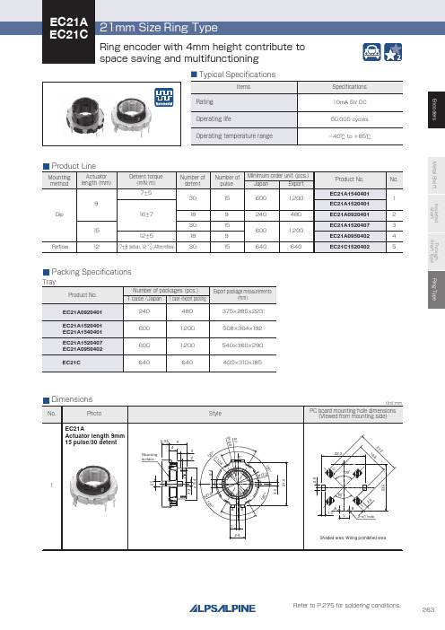
Through shaft type
Horizontal
Horizontal
—
12/12
12/24 12/12
9/18 15/30
Ring type
— 15/30
Features
W
Dimensions (mm)
D
H
Operating temperature range
Operating life Automotive use Life cycle (availability)
300V AC for 1minute or 360V AC for 2s
300V AC for 1minute or 360V AC for 1s
—
7±5mN・m 12±5mN・m 16±7mN・m
—
17±8mN・m(Initial) 12+− 74mN・m(After reflow)
100N
Shaft configuration
1
Style
5-3.5 9
4 Mounting surface
3 2
120°
ø21.6
C ø12.2
AB 1
2-8
120°
0.7
2-10.4 120°
Unit:mm
PC board mounting hole dimensions (Viewed from mounting side)
22.3
3
˃˃
˃ $ ˃ $
˃˃
"# "#
EC21A Actuator length 15mm 9 pulse/18 detent
高流直挂NAMUR阀门电磁阀系列产品简介说明书
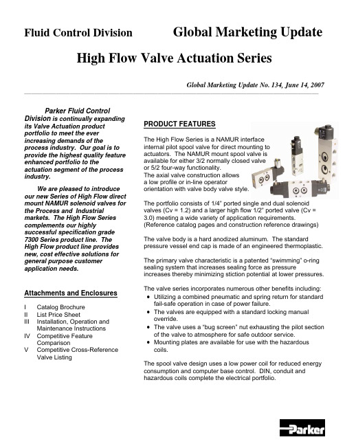
Fluid Control Division Global Marketing Update High Flow Valve Actuation SeriesGlobal Marketing Update No. 134, June 14, 2007 __________________________________________________________________________________________________________________________________ Parker Fluid ControlDivision is continually expanding its Valve Actuation product portfolio to meet the ever increasing demands of the process industry. Our goal is to provide the highest quality feature enhanced portfolio to the actuation segment of the process industry.We are pleased to introduce our new Series of High Flow direct mount NAMUR solenoid valves for the Process and Industrial markets. The High Flow Series complements our highly successful specification grade 7300 Series product line. The High Flow product line provides new, cost effective solutions for general purpose customer application needs.Attachments and EnclosuresI Catalog BrochureII List Price SheetIII Installation, Operation andMaintenanceInstructionsIV Competitive FeatureComparisonV CompetitiveCross-Reference ValveListing PRODUCT FEATURESThe High Flow Series is a NAMUR interfaceinternal pilot spool valve for direct mounting toactuators. The NAMUR mount spool valve isavailable for either 3/2 normally closed valveor 5/2 four-way functionality.The axial valve construction allowsa low profile or in-line operatororientation with valve body valve style.The portfolio consists of 1/4” ported single and dual solenoid valves (Cv = 1.2) and a larger high flow 1/2” ported valve (Cv = 3.0) meeting a wide variety of application requirements. (Reference catalog pages and construction reference drawings)The valve body is a hard anodized aluminum. The standard pressure vessel end cap is made of an engineered thermoplastic.The primary valve characteristic is a patented “swimming” o-ring sealing system that increases sealing force as pressure increases thereby minimizing stiction potential at lower pressures. The valve series incorporates numerous other benefits including: •Utilizing a combined pneumatic and spring return for standard fail-safe operation in case of power failure.•The valves are equipped with a standard locking manual override.•The valve uses a “bug screen” nut exhausting the pilot section of the valve to atmosphere for safe outdoor service.•Mounting plates are available for use with the hazardous coils.The spool valve design uses a low power coil for reduced energy consumption and computer base control. DIN, conduit and hazardous coils complete the electrical portfolio.Global Marketing Update No. 134, June 14, 2007 __________________________________________________________________________________________________________________________________ OPERATION FUNCTIONALITY3/2 Single Solenoid (4 ported, 2 position)NAMUR valve, solenoid operated, for 3-way normally closed operation. In case of an electrical or air failure, valve returns to a fail-safe position through pneumatic and assisted spring return.5/2 Single Solenoid (5 ported, 2 position)NAMUR valve solenoid operated, for 4-way, 2 position operation. In case of an electrical or air failure, valve returns to a fail-safe position through pneumatic and assisted spring return.5/2 Dual Solenoid (5 ported, 2 position)NAMUR valve used for 4-way, 2-position operation. In case of an electrical or air failure, valve “fails as is”. Therefore, valve remains in last position upon failure and will not return to a predetermined position.5/3 Dual Solenoid, Center Position Closed (5 ported, 2 position)NAMUR valve used for 4-way, 2-position operation. In case of an electrical or air failure, the spool returns to the center position thereby removing pressure to the cylinder ports.TECHNICAL PRODUCT CHARACTERISTICSThe new line of valve actuation products offer many features and benefits as follows:Modular construction – Facilitates use of various body configurations and coil options.Mounting Configurations - Direct mount NAMUR pattern with axial operator orientation for single and dual solenoid models for low profile mounting requirements.Manual Override – Standard on all models for manual valve operation during start-up and diagnostic procedures.7mm (1.2Cv ) and 12mm (3.0 Cv) orifice sizes – Multiple sizes to meet various application demands to ensure the solenoid valve is properly sized.Body Materials - Lightweight anodized aluminum.Spool Design – Stainless steel with NBR sealing materials.Exhaust Pilot Cap– Protected pilot sleeve exhaust using “Bug Screen” nut. Helps protect against plugging, dirt, and insects, etc.Ratings – Meets pressures up to 150 psi.Ambient Temperatures – From 14°F (-10°C) to 122°F (50°C), serving most temperature environments. Fluid Temperatures – From 32°F (0°C) to 104°F (40°C).COIL PRODUCT CHARACTERISTICSA selection of low power encapsulated coils as follows:•DIN coil - with 3-pin DIN 43650 type B plug.•Conduit - 3-wire coil.•Hazardous – 3-wire coil with FM and CSA agency approvals meeting Class 1, Groups A,B,C,D and Class II, Groups E,F,G. Meets EEx m II T4 Division 1 requirements.NAMUR INTERFACEMany actuator manufacturers utilize a common mounting pattern referred to as a NAMUR interface for mounting configurations of solenoid valves.The actuator interface dimensions for NAMUR mounting of the pilot valve to the actuator is shown below (dimensions in millimeters).MATERIALS OF CONSTRUCTIONBody: Anodized AluminumEnd Covers: Thermoplastic – Glass-Filled Polyamid 6/6Plunger: 430 Stainless SteelCore Tube: 304 Stainless SteelSteelSprings: StainlessSeals: NBRCages: Polyamide Filled ThermoplasticSteelSpool: StainlessShading Rings: CopperMOUNTING BOLTSThe standard NAMUR interface includes (2) mounting bolts to mount the valve on to the actuator, a positioning stud and two O-rings seals.MOUNTING PLATESDue to the increased width of the hazardous coil to comply with FM and CSA certifications, a mounting plate must be installed as shown in the photograph.The mounting plate kit contains the plate, 2 o-rings, and 2 longer mounting screws.For the ¼” port valve, order kit N60001. For the ½ “ port valve, order kit N60002.ElectricalStandard voltages and voltage code:VOLTAGE CODE 12VDC A 24VDC B 120/60 C 240/60 D 24/60 E 120/50-60 F 240/50-60 GSolenoid Coil SpecificationsThe electrical portfolio is comprised of general purpose class F DIN coil per 43650B and conduit class H coils rated for NEMA classification Types, 1, 2, 3, 3S, 4, 4X. In addition, the hazardous location class H coil is rated for NEMA classification Types 7 and 9; Class I, Divisions 1 and 2, Groups A,B,C,D and Class II, Division 1, Groups E,F,G. The coils are rated for continuous duty application demands.The electrical selector table summarizes each coil specification:Coil Type Coil Part Number Class Protection Construction Agency22mm DINND1x F DIN connector needed for IP65 protection Per DIN 43650B epoxy moldedUL,CSA Conduit –Ordinary locationNC1x H Type 1,2,3,3S,4,4X Epoxy molded, ½ inch NPT conduit None Conduit –Hazardous locationNH1xHType 4X,7,9½ inch NPT conduitCSA,FMCOMPETITIVE FEATURES AND BENEFITSThe primary valve characteristic is a patented “swimming” o-ring sealing system that increases sealing force as pressure increases thereby minimizing stiction potential at lower pressures.The diagram shows a typical cross section view of the valve.valve-head to keep moisture out in brass or in stainless steel available on request, only in combination with alu-head Spool in stainless steel, other inner-parts made from brass, NBR, POM stainless steel Fiber-enforced PA-head, aluminium-version on request 360° turnable,Date CodePRODUCT LABELINGValves are sold in either:• A modular format ordering pressure vessel and coil separately. • Fully assembled with coil assembled to pressure vessel.In either case, the pressure vessel valve body provides the valve identification information defining the valve part number, performance rating and date code. Sample pressure vessel markingCoils will be marked with the appropriate part number, voltage and wattage, and agency information.Sample coil markingAll valves will be packaged with an installation, operation and maintenance instruction sheet indicating conformity with the CE Mark.ORDERING INFORMATIONPRODUCT OFFERINGReference the enclosed catalog brochure (Attachment I) describing the High Flow Series product offering. The catalog pages describe the valve features, general specifications, valve and electrical selection guide, dimensional drawings, and ordering information.PRICINGPressure Vessel list prices for the High Flow NAMUR Series valves are shown in Attachment II. ORDERING INFORMATIONThe Series uses a simple valve number to identify each model. The valves are available fully assembled or in modular form allowing application flexibility in electrical selection. The electrical parts can also be purchased in modular form.Reference the enclosed catalog pages.•When purchasing individual pressure vessels, select the pressure vessel shown on the catalog page and associated list price.•When ordering electrical parts, select the electrical part and associated list price for standard voltages.•When ordering complete valves, add the list price of each component to determine the complete list price for the fully assemble valve selected.The voltage code is the last character of the fully assembled valve or electrical part selected. For example, selecting a single solenoid, 5/2 configuration, 120/60 DIN coil, the complete valve number is:U341N03 + ND1FAVAILABILITY AND DELIVERYParker Fluid Control Division plans to maintain an appropriate service level of finished goods stock to meet business demand of the following NAMUR mount valves. If finished goods stock is available, units will be shipped within 5 business days from receipt of order for order quantities of 25 units or fewer:Product Class 1 Items:U331N03U341N03ND1B, ND1F, ND1G - 24vdc, 120vac, 240vacNC1B, NC1F, NC1G - 24vdc, 120vac, 240vacNH1B, NH1F, NH1G - 24vdc, 120vac, 240vacProduct Class 4 Items - the estimated lead-time (subject to change) is 4 weeks from receipt of order.U347N03U342N03U331N04U341N04ND1A - 12vdcNC1A - 12vdcNH1A - 12vdcAs always, for larger customer orders requiring shorter lead-times, Parker Fluid Control Division will work jointly with each customer by establishing finished goods items to meet customer provided forecasts.DISCOUNTSParker Fluid Control Division’s standard published discounts apply. Current terms and conditions apply for the product.SERVICERETURNSParker Fluid Control Division’s standard return policy applies.REPAIR PARTSParker Fluid Control Division is NOT offering component repair kits for field service at this time. Since the valve is a small, cost effective product, industry experience shows the process markets will replace the complete valve rather than rebuild the valve in the field.INSTALLATION OPERATION AND MAINTENANCE (IOM)An IOM has been created describing valve operation, installation and mounting instructions, maintenance, and troubleshooting procedures for the high flow Series NAMUR valves. Reference Attachment III, IOM HN01.WARRANTYParker Skinner’s standard 2 year warranty policy applies to the pressure vessel, coil and enclosures.PROMOTIONPromotional materials have been prepared to expedite introduction into the market place.CATALOG / LITERATURE• A new catalog has been created containing the features, specifications and outline drawings of the high flow Series valves.• A product launch announcement containing product introduction materials and detailed competitor information will be distributed to each Territory Sales Manager.TRAINING•Each Territory Sales Manager should contact their respective Fluid Control Division Authorized Distributor and Valve Actuation Accounts to arrange training.•The new high flow Series valves will be included in Fluid Control Division’s Valve Actuation Training Program.•Samples of the new high flow Series actuation valves will be provided upon receipt with a complete sample request form following standard Skinner Valve ™ sample procedures.PHASE-OUT OF 2340, 3300 and 7341 Series Product LinesThe introduction of the new product line has resulted in significant product overlap with the 2340, 3300 and 7341 series valves. Therefore, we are taking the following actions to phase out these product lines. Due to the low volume of many of the products, the old families will be replaced by the new High Flow NAMUR valve as follows:The Phase In – Phase Out schedule will begin upon introduction of the new High Flow NAMUR valve. It may be possible to order a specific older model until current inventory is fully depleted at which time the old product will no longer be available. Parker reserves the right to discontinue the old products sooner if conditions warrant.COMPETITIVE REVIEWReference Competitive Feature Comparison of select valves in Attachment IV. The attachment contains a broad selection of valves representative of the competitive offering.Attachment V provides a competitive cross-reference part number listing based on available information for the individual competitors.ASCO is considered the market leader for actuation valves. Other primary competitors include Versa, Automatic, and Herion.Below is a general description of the competitive product offerings.ASCOThe ASCO 8551 Series offers a product line of NAMUR and pipe mount versions. The portfolio consists of pad mount valves with various operator configurations with single and dual solenoids.In general, the ASCO 8551 Series consists of:•Anodized aluminum and stainless steel body using resilient spool construction. •Convertible 3-way and 4-way models based on the newer version. The older version consists of non-convertible 3-way and 4-way models that are similar to the 7300 Series. •20/35 to 150 psi operating pressure differential.•Single and dual solenoid, vertical and axial operator models available.•Cv 0.50 to 0.86.•AC versions from 2.5 watts to 10.1 watts.DC versions from 3.0 watts to 11.6 watts.•DIN, watertight and explosion solenoids available based on model.The Parker High Flow Series NAMUR mount valves are specified to meet the application requirement. A conversion or mounting plate is not required when using a DIN coil. The valve mounts directly to the actuator in a very cost-effective and efficient manner.VersaVersa offers a series of valves for process control markets including applications for pneumatic actuators and 316 stainless valves for corrosive requirements. The valve offering consists of NAMUR, body ported, lockout valves, latching and manual reset valves and redundant solenoid valves.Specific to the actuation area, Versa offers a convertible 3-way / 4-way version and direct acting 3-way pad mount valve. Available options include Intrinsically Safe, Low power and CENELEC flameproof enclosures.•3/2, 5/2 port plug versions. Valves field convertible by relocating a port plug converting from 3-way to 4-way or 4-way to 3-way.•Anodized aluminum, stainless steel and brass body using resilient spool construction. •Single and dual solenoid models (5/2) and dual solenoid centered position (5/3) with standard manual override.•15 to 115 psi operating pressure, Cv 0.75.•DIN, conduit and explosion solenoids available based on model.•8.5 watt AC, 10.5 watt DC.•Class A or F insulation.Automatic Valve Co. (AVC)They are considered the low price player in the market. They offer a NAMUR mount COMPACT Series. The series has limited options, but offers the ability to order valves with the solenoid on the left or right side.•3/2, 5/2 port plug versions, 1/4” npt porting only.•Anodized aluminum body using resilient spool construction.•40 to 150 psi operating pressure differential, Cv 1.0.•NEMA 4 and 7 solenoids, remote air and manual operators.•DIN, conduit and explosion solenoids available based on model, coil ratings to Class H. Herion•3/2, 5/2 port plug versions, NAMUR mount, 1/8” NPT, ¼” NPT, ½” NPT.•Anodized aluminum body using resilient spool construction.•25 to 150 psi operating pressure differential, Cv 1.1 to 1.4.•NEMA 4 and 7 solenoids, manual operators.•Low power coils available at reduced ratings.•DIN, conduit and explosion solenoids available based on models.•Locking and momentary manual override available.•Requires spacer plate for hazardous coil.Max-Air TechnologyU.S. division of M Technology Srl located in Italy. Also offer rack & pinion actuators and position indicators and mechanical switches that can be assembled as a complete unit.•3/2, 5/2 port plug versions, 1/4” npt porting only.•Epoxy coated aluminum body with plated spool. And standard manual override.•DIN and explosion solenoids available based on model, Class F standard, Class H optional. •Uses a pop-up air indicator located in pilot section to indicate if the solenoid valve is pressurized.•Optional IS and ATEX DIN coil construction.Q&A SESSIONQ? Why did we introduce the High Flow NAMUR Series valve product line?The principle reason for introducing the valve line is to meet increasing market demands for smaller, cost effective valve models for the process valve actuation markets. The Parker 7300 Series valve line offers a high-end specification grade product in multiple bodymaterials to meet general purpose ordinary requirements to the most stringent application requirements. Also, the 2340 series of aluminum body valves lacked a suitable hazardous coil limiting application potentials.The new product line overcomes the 2340 series deficiencies at a most competitive price for general purpose application requirements. The portfolio includes expanded models with higher flow factors for larger actuator designs. The new line includes a 1/2” namur valve to accommodate the trend toward larger actuators and higher flows.Finally, we’re continuing our strategic thrust in the process markets with a new product offering and responding to competitive product positions.Q? Will the High Flow Series product line replace the 2340 Series and 3300 Series valves?In a word, yes. First, since the introduction of the 2340 series and 3300 series valves(dating back to the late ‘90’s), many changes have taken place in the market. The general purpose ordinary location market generally does not require the high technical or safety standards found in these product lines. Due to deficiencies in the former product lines, specifically the lack of a hazardous coil, we were not able to meet the availability and price competitiveness. The current product lines are focused toward higher technicalrequirements resulting in low-volume market segments and overlap price-wise with the 7300 Series valve lines. To reduce complexity and offer a simplified, cost-effective processactuation valve line, the 2340 catalog portfolio will (eventually) be phased-out.Q? Describe the comparison to the 7300 product line.The High Flow Series offers similar product features and benefits compared to the 7300 Series, in particular:• Total modularity.•Interchangeable electrical parts.•Unique spool designs to eliminate risk of sticking.•High quality in proven valve designs.•Standard manual override.The distinctive features of the High Flow Series compared to the 7300 Series include:• Smaller physical size.•More cost effective compared to 7300 with manual override (for certain type application needs).Q? Where must the 7300 series valves be used versus the new line?The 7300 series contains features, multiple operator configurations and electrical coilsappropriate for more demanding critical applications including:•Higher flows appropriate for higher actuator torque specifications.•Intrinsically Safe (IS) and ultra low power environmental conditions.•Manual reset options used as a safety device on solenoid valves to prevent process resumption without manually resetting each valve.•Low temperatures application demands of –40°F/C.•Field convertible manual overrides including locking and momentary requirements. Q? Will a conversion plate eventually become available?The product line contains individual 3-way and 4-way valve configuration. When utilizing a DIN coil, this method provides the most cost-effective, competitive solution. Granted, whilea conversion plate offers the benefit of using one style valve, it also adds significant andunnecessary costs. Since the valve is focused and priced to pursue higher volumerequirements, the valve functionality will be known.。
FU-632SEA-6M91A中文资料

MITSUBISHI (OPTICAL DEVICES) FU-632SEA-3MxxA/FU-632SEA-6MxxA1.55 m m EAM/DFB-LD MODULE WITH SINGLEMODE FIBER PIGTAIL(WDM)DESCRIPTIONModule type FU-632SEA-6MxxA is an electro-aborption modulator integrated with 1.55m m DFB-LDmodule with single mode optical fiber.This module is suitable to a light source in 2.5Gb/sdigital optical communication systems where thedistance is shorter than 640km.This module is prepared in accordance with ITU-Trecommendation wavelength channel plan for Dense-WDM transmission.FEATURESDistributed feedback (DFB) Laser DiodeBuilt-in optical isolator1.55 m m EAM/DFB-LD MODULE WITH SINGLEMODE FIBER PIGTAIL(WDM)ELECTRICAL/OPTICAL CHARACTERISTICS (Tld=Tset, Tc=25°C unless otherwise noted)Parameter Symbol Test Conditions Limits UnitMin.Typ.Max.Laser operatingTemperatureTset CW, If=Iop15-35°C Threshold current Ith CW,Vm=0V5-30mA Operating current Iop CW,Vm=0V5060100mA Operating voltage Vop CW,Vm=0V,If=Iop-- 1.7VInput impedance Zin If=Iop-50-W Optical output power fromfiber endPf CW,Vm=0V,If=Iop 1.2--mWLight emission central spectral wavelength l c CW,Vm=0V,If=Iop,Tld=Tsetsee Table 1.nmCenter wavelength drift with case temperature Dl c/D Tc CW,Vm=0V,APCTld=Tset ,Tc=-20~70°C-1-0pm/°CSide mode suppressionratioSr(Note3,5)3540-dBSpectral width Dl(Note3,5)-310MHz Relative intensity noise RIN CW,Vm=0V,If=Iop,2.5GHz--155-140dB/Hz-3MxxA series @6400ps/nm -- 1.0dBPower penalty Pp(Note4,5)-6MxxA series@12800ps/nm-- 1.0dBExtinction ratio Ex(Note3,5)11--dB Rise/Fall time tr/tf(Note3,5),10-90%--120ps Cutoff frequency fc If=Iop,Vm=-1V 3.5--GHzIf=Iop,Vm=-1V,0~2GHz10--dBIf=Iop,Vm=-1V,2~3GHz7--dB RF return loss S11If=Iop,Vm=-1V,3~5GHz3--dB Tracking error Er Tc=-201.55 m m EAM/DFB-LD MODULE WITH SINGLEMODE FIBER PIGTAIL(WDM)THERMAL CHARACTERISTICS (Tld=Tset, Tc=-20~70°C)Parameter Symbol Test Conditions Limits UnitMin.Typ.Max.Thermistor resistance Rth Tld=25°C9.51010.5k WB constant of Rth B--3950-KCooler current Ipe If=Iop,Tld=Tset,Tc=70°C-0.7 1.2ACooler voltage Vpe If=Iop,Tld=Tset,Tc=70°C- 1.7 2.5VFIBER PIGTAIL SPECIFICATIONSParameter Limits UnitType SM-Mode field diameter9.50.1mmOptical return loss of connector40 (min)dBDOCUMENTATION (Tld=Tset)Threshold current (Ith) at Tld=Tset and Tc=25°C.Laser operating temperature (Tset) at l c. (Note 7)Cooler current (Ipe) at Pf=1.2mW, Vm=0V, Tld=Tset and Tc=70°C.1.55 m m EAM/DFB-LD MODULE WITH SINGLEMODE FIBER PIGTAIL(WDM) Table 1. (All wavelengths are referred to vacuum. Tolerance is l c1.55 m m EAM/DFB-LD MODULE WITH SINGLEMODE FIBER PIGTAIL(WDM) OUTLINE DIAGRAM(Unit : mm)FU-632SEA-3MxxA/FU-632SEA-6MxxA。
9926a中文手册
nA
开启特性(注2)
VGS(th)
栅极阈值电压
VDS= VGS, ID= 250A
0.6
1.0
1.5
V
栅极阈值电压温度系数
ID= 250A, Referenced to 25℃
–3
mV/°C
RDS(on)
静态漏源导通电阻
VGS= 4.5 V, ID= 4.5 A
VGS= 2.5 V, ID= 3.8 A
b)当安装在安装在FR-4的最小铜焊垫上,RθJA是208°C/ W(稳态)。
2.脉冲测试:脉冲宽度<300毫秒,占空比<2.0%
典型特性曲线
图一导通区特性图二导通电阻与漏电流和栅极电压的变化
图三导通电阻随温度的变化图四导通电阻与栅源电压的变化
图五传输特性图六体二极管正向电压与源电流
和温度的变化
典型特性曲线
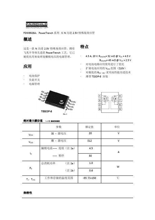
FDW9926A:PowerTrench系列双N沟道2.5V特殊场效应管
概述
这是一款N沟道2.5V特殊场效应管,拥有飞兆半导体先进的PowerTrench工艺。它已被优化用来处理宽栅极电压的电源管理。
应用
电池保护
负荷开关
电源管理
特点
4.5 A, 20 V. RDS(ON)= 32 mΩ @ VGS= 4.5 V
15
ns
tf
关断下降时间
4
8
ns
Qg
总栅极电荷
VDS= 10 V, ID= 4.5 A,
VGS= 4.5 V
6.1
9
nC
Qgs
栅源电荷
1.1
nC
Qgd
栅漏电荷
1.8
nC
SCM6323AYJ12A资料

8
LB UB
BYTE ENABLE BUFFER
HIGH BYTE WRITE ENABLE LOW BYTE WRITE ENABLE
This document contains information on a new product under development. Motorola reserves the right to change or discontinue this product without notice. REV 1 10/17/97
Emulex CN4052S 和 CN4054S 10Gb VFA5.2 适配器商品说明说明书

Emulex CN4052S and CN4054S 10Gb VFA5.2 Adapters for Flex SystemProduct GuideThe CN4054S 4-port and CN4052S 2-port 10Gb Virtual Fabric Adapters are VFA5.2 adapters that are supported on ThinkSystem and Flex System compute nodes.The CN4052S can be divided into up to eight virtual NIC (vNIC) devices per port (for a total of 16 vNICs) and the CN4054S can be divided in to four vNICs (for a total of 16 vNICs). Each vNIC can have flexible bandwidth allocation. These adapters also feature RDMA over Converged Ethernet (RoCE) capability, and support iSCSI, and FCoE protocols, either as standard or with the addition of a Features on Demand (FoD) license upgrade.The adapters are shown in the following figure. The CN4054S and CN4052S look the same.Figure 1. Flex System CN4054S and CN4052S 10Gb Virtual Fabric AdaptersDid you know?The CN4054S and CN4052S are based on the new Emulex XE100-P2 "Skyhawk P2" ASIC which enables better performance, especially with the new RDMA over Converged Ethernet v2 (RoCE v2) support. In addition, these adapters are supported by Lenovo XClarity Administrator, which allows you to deploy adapter settings easier and incorporate the adapters in configuration patterns.The CN4052S adapter now supports 8 vNICs per port using UFP or vNIC2 and with adapter firmware 10.6 or later. This means a total of 16 vNICs are supported. The CN4054S still supports 4 vNICs per port.Click here to check for updatesIn pNIC mode, an adapter with the FoD upgrade applied operates in traditional Converged Network Adapter (CNA) mode with four ports (CN4054S) or two ports (CN4052S) of Ethernet and four ports (CN4054S) or two ports (CN4052S) of iSCSI or FCoE available to the operating system.Server supportThe following table lists the ThinkSystem and Flex System compute nodes that support the adapters. Table 2. Support for Flex System compute nodesPartnumber DescriptionAdapters - ThinkSystem and Flex System compute nodes01CV780Flex System CN4052S 2-port 10Gb Virtual FabricAdapter AdvancedN N Y Y Y Y Y Y Y Y00AG540Flex System CN4052S 2-port 10Gb Virtual FabricAdapterN N Y Y Y N Y Y Y Y00AG590Flex System CN4054S 4-port 10Gb Virtual FabricAdapterY Y Y Y Y Y Y Y Y Y Features on Demand upgrades - Flex System compute nodes only00JY804Flex System CN4052 Virtual Fabric Adapter SWUpgrade (FoD)Y Y Y Y Y Y Y N N N00AG594Flex System CN4054S 4-port 10Gb Virtual Fabric Adapter SW Upgrade (FoD)Y Y Y Y Y Y Y N N N x24(8737,E5-26v2)x24(7162)x24M5(9532,E5-26v3)x24M5(9532,E5-26v4)x44(7167)x88/x48/x28X6(793)x28/x48/x88X6(7196)SN55(7X16)SN85(7X15)SN55V2(7Z69)I/O module supportThese adapters can be installed in any I/O adapter slot of a supported Flex System compute node. One or two compatible 1 Gb or 10 Gb I/O modules must be installed in the corresponding I/O bays in the chassis. The following table lists the switches that are supported. When connected to the 1 Gb switch, the adapter will operate at 1 Gb speeds. When connected to the 40 Gb switch, the adapter will operate at 10 Gb speeds.To maximize the number of adapter ports usable, you may also need to order switch upgrades to enable additional ports. Alternatively, for CN4093, EN4093R, and SI4093 switches, you can use Flexible Port Mapping (FPM), a feature of Networking OS 7.8 or later, that allows you to minimize the number of upgrades needed.See the Product Guides for the Flex System switches for more details about switch upgrades and FPM: https:///servers/blades/networkmoduleThe table below specifies how many ports the adapters contain. For the CN4054S, to enable all 4 adapter ports, either upgrade the switch or use Flexible Port Mapping. Switches should be installed in pairs to maximize the number of ports enabled and to provide redundant network connections.Table 3. I/O modules supportedPartnumber Description CN4052Sports†CN4054Sports†4SG7A08868Lenovo ThinkSystem NE2552E Flex Switch2400FM514Lenovo Flex System Fabric EN4093R 10Gb Scalable Switch24**00FM510Lenovo Flex System Fabric CN4093 10Gb Converged Scalable Switch24**00FE327Lenovo Flex System SI4091 10Gb System Interconnect Module2200FM518Lenovo Flex System Fabric SI4093 System Interconnect Module24**90Y9346Flex System EN6131 40Gb Ethernet Switch2288Y6043Flex System EN4091 10Gb Ethernet Pass-thru2249Y4294Flex System EN2092 1Gb Ethernet Scalable Switch24**94Y5350Cisco Nexus B22 Fabric Extender for Flex System2200D5823*Flex System Fabric CN4093 10Gb Converged Scalable Switch24**95Y3309*Flex System Fabric EN4093R 10Gb Scalable Switch24**49Y4270*Flex System Fabric EN4093 10Gb Scalable Switch24**95Y3313*Flex System Fabric SI4093 System Interconnect Module24**94Y5212*Flex System EN4023 10Gb Scalable Switch24*** Withdrawn from marketing† This is the number of adapter ports that will be enabled per adapter, and requires that two switches be installed in the chassis.** The use of 4 ports will require either a switch upgrade to enable additional ports or the use of Flexible Port Mapping to reconfigure the active portsThe following table shows the connections between adapters installed in the compute nodes and the switch bays in the chassis.Table 4. Adapter to I/O bay correspondenceI/O adapter slot in the server Port on the adapter Corresponding I/O module bayin the chassisSlot 1Port 1Module bay 1Port 2Module bay 2Port 3*Module bay 1Port 4*Module bay 2 Slot 2Port 1Module bay 3Port 2Module bay 4Port 3*Module bay 3Port 4*Module bay 4Slot 3(full-wide compute nodes only)Port 1Module bay 1 Port 2Module bay 2 Port 3*Module bay 1 Port 4*Module bay 2Slot 4(full-wide compute nodes only)Port 1Module bay 3 Port 2Module bay 4 Port 3*Module bay 3 Port 4*Module bay 4* Ports 3 and 4 (CN4054S only) require Upgrade 1 of the selected switch, where applicable. 14-port modules such as the EN4091 Pass-thru, SI4091 switch, and Cisco B22 only support ports 1 and 2 (and only when two I/O modules are installed).The following figure shows the internal layout of the CN4054S, with how the adapter ports are routed to the I/O module internal ports.Note: INTD1 is not available on any currently shipping Flex System I/O modules.Figure 2. Internal layout of the CN4054S adapter portsThe following figure shows the internal layout of the CN4052S, and how the adapter ports are routed to the I/O module internal ports.Note: INTD1 is not available on any currently shipping Flex System I/O modules.Figure 3. Internal layout of the CN4052S adapter portsThe connections between the adapters installed in the compute nodes to the switch bays in the chassis are shown diagrammatically in the following figure. The figure shows half-wide servers (such as the x240 M5 with two adapters) and full-wide servers (such as the x440 with four adapters).Figure 4. Logical layout of the interconnects between I/O adapters and I/O modulesSUSE Linux Enterprise Server 12 SP2N N N Y Y Y Y Y SUSE Linux Enterprise Server 12 SP2 with Xen N N N Y Y Y Y Y SUSE Linux Enterprise Server 12 SP3N N N Y Y Y Y Y SUSE Linux Enterprise Server 12 SP3 with Xen N N N Y Y Y Y Y SUSE Linux Enterprise Server 12 SP4N Y Y Y Y Y Y Y SUSE Linux Enterprise Server 12 SP4 with Xen N Y Y Y Y Y Y Y SUSE Linux Enterprise Server 12 SP5Y Y Y Y Y Y Y Y SUSE Linux Enterprise Server 12 SP5 with Xen Y Y Y Y Y Y Y Y SUSE Linux Enterprise Server 15N Y Y Y Y Y Y N SUSE Linux Enterprise Server 15 SP1N Y Y Y Y Y Y N SUSE Linux Enterprise Server 15 SP1 with Xen N Y Y Y Y Y Y N SUSE Linux Enterprise Server 15 SP2Y Y Y Y Y Y Y N SUSE Linux Enterprise Server 15 SP2 with Xen Y Y Y Y Y Y Y N SUSE Linux Enterprise Server 15 SP3Y Y Y Y Y N N N SUSE Linux Enterprise Server 15 SP3 with Xen Y Y Y Y Y N N N SUSE Linux Enterprise Server 15 SP4Y Y Y Y Y N N N SUSE Linux Enterprise Server 15 SP4 with Xen Y Y Y Y Y N N N SUSE Linux Enterprise Server 15 SP5Y Y Y Y Y N N N SUSE Linux Enterprise Server 15 SP5 with Xen Y Y Y Y Y N N N SUSE Linux Enterprise Server 15 with Xen N Y Y Y Y Y Y N Ubuntu 18.04.5 LTSY N N N N N N N VMware vSphere Hypervisor (ESXi) 5.5N N N N N Y N Y VMware vSphere Hypervisor (ESXi) 6.0 U3N N N Y Y Y N Y VMware vSphere Hypervisor (ESXi) 6.5N N N Y Y Y Y N VMware vSphere Hypervisor (ESXi) 6.5 U1N N N Y Y Y Y N VMware vSphere Hypervisor (ESXi) 6.5 U2N Y Y Y Y Y Y N VMware vSphere Hypervisor (ESXi) 6.5 U3N Y Y Y Y Y Y N VMware vSphere Hypervisor (ESXi) 6.7N N N Y Y Y N N VMware vSphere Hypervisor (ESXi) 6.7 U1N Y Y Y Y Y N N VMware vSphere Hypervisor (ESXi) 6.7 U2N Y Y Y Y Y N N VMware vSphere Hypervisor (ESXi) 6.7 U3Y Y Y Y Y Y N N VMware vSphere Hypervisor (ESXi) 7.0N Y Y Y Y N N N VMware vSphere Hypervisor (ESXi) 7.0 U1N Y Y Y Y N N N VMware vSphere Hypervisor (ESXi) 7.0 U2Y Y Y Y Y N N NOperating systemsS N 550 V 2S N 550 (X e o n G e n 2)S N 850 (X e o n G e n 2)S N 550 (X e o n G e n 1)S N 850 (X e o n G e n 1)x 240 M 5 (9532)x 280/x 480/x 880 X 6 (719x 440 (7167)VMware vSphere Hypervisor (ESXi) 7.0 U3Y Y Y Y Y N N NOperating systemsTable 6. Operating system support for Flex System CN4054S 4-port 10Gb Virtual Fabric Adapter, 00AG590Operating systemsMicrosoft Windows Server 2012N N N N N Y Y Y N Y Y Y Microsoft Windows Server 2012 R2N N N Y Y Y Y Y N Y Y Y Microsoft Windows Server 2016Y Y Y Y Y Y N Y N Y Y N Microsoft Windows Server 2019Y Y Y Y Y N N Y N N N N Microsoft Windows Server 2022Y Y Y Y Y N N N N N N N Microsoft Windows Server version 1709N N N Y Y N N Y Y N Y N Microsoft Windows Server version 1803N N N Y N N N N N N N N Red Hat Enterprise Linux 6.10N N N Y Y Y Y Y Y Y Y Y Red Hat Enterprise Linux 6.9N N N Y Y Y Y Y Y Y Y Y Red Hat Enterprise Linux 7.3N N N Y Y Y Y Y Y Y Y Y Red Hat Enterprise Linux 7.4N N N Y Y Y Y Y Y Y Y Y Red Hat Enterprise Linux 7.5N N N Y Y Y Y Y Y Y Y Y Red Hat Enterprise Linux 7.6N Y Y Y Y Y Y Y Y Y Y Y Red Hat Enterprise Linux 7.7N Y Y Y Y Y Y Y Y Y Y Y Red Hat Enterprise Linux 7.8N Y Y Y Y Y Y Y Y Y Y Y Red Hat Enterprise Linux 7.9Y Y Y Y Y Y Y Y Y Y Y Y Red Hat Enterprise Linux 8.0N Y Y Y Y N N N N N N N Red Hat Enterprise Linux 8.1N Y Y Y Y N N N N N N N Red Hat Enterprise Linux 8.2Y Y Y Y Y N N N N N N N Red Hat Enterprise Linux 8.3Y Y Y Y Y N N N N N N N Red Hat Enterprise Linux 8.4Y Y Y Y Y N N N N N N N Red Hat Enterprise Linux 8.5Y Y Y Y Y N N N N N N N Red Hat Enterprise Linux 8.6Y Y Y Y Y N N N N N N N Red Hat Enterprise Linux 8.7Y Y Y Y Y N N N N N N NS N 550 V 2S N 550 (X e o n G e n 2)S N 850 (X e o n G e n 2)S N 550 (X e o n G e n 1)S N 850 (X e o n G e n 1)x 240 M 5 (9532)x 280/x 480/x 880 X 6 (719x 440 (7167)S N 550 V 2S N 550 (X e o n G e n 2)S N 850 (X e o n G e n 2)S N 550 (X e o n G e n 1)S N 850 (X e o n G e n 1)x 240 (8737, E 5 v 2)x 240 (7162)x 240 M 5 (9532)x 280/x 480/x 880 X 6 (7196)x 280/x 480/x 880 X 6 (7903)x 440 (7167)x 440 (7917)SUSE Linux Enterprise Server 11 SP4N N N Y Y Y Y Y N Y Y Y SUSE Linux Enterprise Server 11 SP4 with Xen N N N Y Y Y Y Y N Y Y Y SUSE Linux Enterprise Server 11 for x86N N N N N N Y N N N Y N SUSE Linux Enterprise Server 12 SP2N N N Y Y Y Y Y Y Y Y Y SUSE Linux Enterprise Server 12 SP2 with Xen N N N Y Y Y Y Y Y Y Y Y SUSE Linux Enterprise Server 12 SP3N N N Y Y Y Y Y Y Y Y Y SUSE Linux Enterprise Server 12 SP3 with Xen N N N Y Y Y Y Y Y Y Y Y SUSE Linux Enterprise Server 12 SP4N Y Y Y Y Y Y Y Y Y Y Y SUSE Linux Enterprise Server 12 SP4 with Xen N Y Y Y Y Y Y Y Y Y Y Y SUSE Linux Enterprise Server 12 SP5Y Y Y Y Y Y Y Y Y Y Y Y SUSE Linux Enterprise Server 12 SP5 with Xen Y Y Y Y Y Y Y Y Y Y Y Y SUSE Linux Enterprise Server 15N Y Y Y Y N N Y Y N N N SUSE Linux Enterprise Server 15 SP1N Y Y Y Y N N Y Y N N N SUSE Linux Enterprise Server 15 SP1 with Xen N Y Y Y Y N N Y Y N N N SUSE Linux Enterprise Server 15 SP2Y Y Y Y Y N N Y Y N N N SUSE Linux Enterprise Server 15 SP2 with Xen Y Y Y Y Y N N Y Y N N N SUSE Linux Enterprise Server 15 SP3Y Y Y Y Y N N N N N N N SUSE Linux Enterprise Server 15 SP3 with Xen Y Y Y Y Y N N N N N N N SUSE Linux Enterprise Server 15 SP4Y Y Y Y Y N N N N N N N SUSE Linux Enterprise Server 15 SP4 with Xen Y Y Y Y Y N N N N N N N SUSE Linux Enterprise Server 15 SP5Y Y Y Y Y N N N N N N N SUSE Linux Enterprise Server 15 SP5 with Xen Y Y Y Y Y N N N N N N N SUSE Linux Enterprise Server 15 with Xen N Y Y Y Y N N Y Y N N N Ubuntu 18.04.5 LTSY N N N N N N N N N N N VMware vSphere Hypervisor (ESXi) 5.5N N N N N Y Y Y N Y Y Y VMware vSphere Hypervisor (ESXi) 6.0 U3N N N Y Y Y Y Y Y Y Y Y VMware vSphere Hypervisor (ESXi) 6.5N N N Y Y Y N Y Y Y N N VMware vSphere Hypervisor (ESXi) 6.5 U1N N N Y Y Y N Y Y Y N N VMware vSphere Hypervisor (ESXi) 6.5 U2N Y Y Y Y Y N Y Y Y N N VMware vSphere Hypervisor (ESXi) 6.5 U3N Y Y Y Y Y N Y Y Y N N VMware vSphere Hypervisor (ESXi) 6.7N N N Y Y N N Y N N N N VMware vSphere Hypervisor (ESXi) 6.7 U1N Y Y Y Y N N Y N N N N VMware vSphere Hypervisor (ESXi) 6.7 U2N Y Y Y Y N N Y N N N N VMware vSphere Hypervisor (ESXi) 6.7 U3Y Y Y Y Y N N Y N N N NOperating systemsS N 550 V 2S N 550 (X e o n G e n 2)S N 850 (X e o n G e n 2)S N 550 (X e o n G e n 1)S N 850 (X e o n G e n 1)x 240 (8737, E 5 v 2)x 240 (7162)x 240 M 5 (9532)x 280/x 480/x 880 X 6 (719x 280/x 480/x 880 X 6 (790x 440 (7167)x 440 (7917)VMware vSphere Hypervisor (ESXi) 7.0N Y Y Y Y N N N N N N N VMware vSphere Hypervisor (ESXi) 7.0 U1N Y Y Y Y N N N N N N N VMware vSphere Hypervisor (ESXi) 7.0 U2Y Y Y Y Y N N N N N N N VMware vSphere Hypervisor (ESXi) 7.0 U3Y Y Y Y Y N N N N N N NOperating systemsTable 7. Operating system support for Flex System CN4052S 2-port 10Gb Virtual Fabric Adapter Advanced,01CV780Operating systemsMicrosoft Windows Server 2012N N N N N Y Y Y Y Microsoft Windows Server 2012 R2N N N Y Y Y Y Y Y Microsoft Windows Server 2016Y Y Y Y Y Y Y Y N Microsoft Windows Server 2019Y Y Y Y Y Y N N N Microsoft Windows Server 2022Y Y Y Y Y N N N N Microsoft Windows Server version 1709N N N Y Y Y Y N N Microsoft Windows Server version 1803N N N Y N N N N N Red Hat Enterprise Linux 6.10N N N Y Y Y Y Y Y Red Hat Enterprise Linux 6.9N N N Y Y Y Y Y Y Red Hat Enterprise Linux 7.3N N N Y Y Y Y Y Y Red Hat Enterprise Linux 7.4N N N Y Y Y Y Y Y Red Hat Enterprise Linux 7.5N N N Y Y Y Y Y Y Red Hat Enterprise Linux 7.6N Y Y Y Y Y Y Y Y Red Hat Enterprise Linux 7.7N Y Y Y Y Y Y Y Y Red Hat Enterprise Linux 7.8N Y Y Y Y Y Y Y Y Red Hat Enterprise Linux 7.9Y Y Y Y Y Y Y Y Y Red Hat Enterprise Linux 8.0N Y Y Y Y N N N N Red Hat Enterprise Linux 8.1N Y Y Y Y N N N N Red Hat Enterprise Linux 8.2Y Y Y Y Y N N N N Red Hat Enterprise Linux 8.3Y Y Y Y Y N N N NS N 550 V 2S N 550 (X e o n G e n 2)S N 850 (X e o n G e n 2)S N 550 (X e o n G e n 1)S N 850 (X e o n G e n 1)x 240 (8737, E 5 v 2)x 240 (7162)x 240 M 5 (9532)x 280/x 480/x 880 X 6 (719x 280/x 480/x 880 X 6 (790x 440 (7167)x 440 (7917)S N 550 V 2S N 550 (X e o n G e n 2)S N 850 (X e o n G e n 2)S N 550 (X e o n G e n 1)S N 850 (X e o n G e n 1)x 240 M 5 (9532)x 280/x 480/x 880 X 6 (7196)x 280/x 480/x 880 X 6 (7903)x 440 (7917)Red Hat Enterprise Linux 8.4Y Y Y Y Y N N N N Red Hat Enterprise Linux 8.5Y Y Y Y Y N N N N Red Hat Enterprise Linux 8.6Y Y Y Y Y N N N N Red Hat Enterprise Linux 8.7Y Y Y Y Y N N N N SUSE Linux Enterprise Server 11 SP4N N N Y Y Y Y Y Y SUSE Linux Enterprise Server 11 SP4 with Xen N N N Y Y Y Y Y Y SUSE Linux Enterprise Server 11 for x86N N N N N N Y N N SUSE Linux Enterprise Server 12 SP2N N N Y Y Y Y Y Y SUSE Linux Enterprise Server 12 SP2 with Xen N N N Y Y N Y Y Y SUSE Linux Enterprise Server 12 SP3N N N Y Y Y Y Y Y SUSE Linux Enterprise Server 12 SP3 with Xen N N N Y Y N Y Y Y SUSE Linux Enterprise Server 12 SP4N Y Y Y Y Y Y Y Y SUSE Linux Enterprise Server 12 SP4 with Xen N Y Y Y Y N Y Y Y SUSE Linux Enterprise Server 12 SP5Y Y Y Y Y Y Y Y Y SUSE Linux Enterprise Server 12 SP5 with Xen Y Y Y Y Y N Y Y Y SUSE Linux Enterprise Server 15N Y Y Y Y Y Y N N SUSE Linux Enterprise Server 15 SP1N Y Y Y Y Y Y N N SUSE Linux Enterprise Server 15 SP1 with Xen N Y Y Y Y Y Y N N SUSE Linux Enterprise Server 15 SP2Y Y Y Y Y Y Y N N SUSE Linux Enterprise Server 15 SP2 with Xen Y Y Y Y Y Y Y N N SUSE Linux Enterprise Server 15 SP3Y Y Y Y Y N N N N SUSE Linux Enterprise Server 15 SP3 with Xen Y Y Y Y Y N N N N SUSE Linux Enterprise Server 15 SP4Y Y Y Y Y N N N N SUSE Linux Enterprise Server 15 SP4 with Xen Y Y Y Y Y N N N N SUSE Linux Enterprise Server 15 SP5Y Y Y Y Y N N N N SUSE Linux Enterprise Server 15 SP5 with Xen Y Y Y Y Y N N N N SUSE Linux Enterprise Server 15 with Xen N Y Y Y Y Y Y N N Ubuntu 18.04.5 LTSY N N N N N N N N VMware vSphere Hypervisor (ESXi) 5.5N N N N N Y Y Y Y VMware vSphere Hypervisor (ESXi) 6.0 U3N N N Y Y Y Y Y Y VMware vSphere Hypervisor (ESXi) 6.5N N N Y Y Y Y Y N VMware vSphere Hypervisor (ESXi) 6.5 U1N N N Y Y Y Y Y N VMware vSphere Hypervisor (ESXi) 6.5 U2N Y Y Y Y Y Y Y N VMware vSphere Hypervisor (ESXi) 6.5 U3N Y Y Y Y Y Y Y NOperating systems S N 550 V 2S N 550 (X e o n G e n 2)S N 850 (X e o n G e n 2)S N 550 (X e o n G e n 1)S N 850 (X e o n G e n 1)x 240 M 5 (9532)x 280/x 480/x 880 X 6 (719x 280/x 480/x 880 X 6 (790x 440 (7917)TrademarksLenovo and the Lenovo logo are trademarks or registered trademarks of Lenovo in the United States, other countries, or both. A current list of Lenovo trademarks is available on the Web athttps:///us/en/legal/copytrade/.The following terms are trademarks of Lenovo in the United States, other countries, or both:Lenovo®Flex SystemServerProven®System x®ThinkSystem®VMready®XClarity®The following terms are trademarks of other companies:Xeon® is a trademark of Intel Corporation or its subsidiaries.Linux® is the trademark of Linus Torvalds in the U.S. and other countries.Microsoft®, Hyper-V®, SQL Server®, SharePoint®, Windows Server®, and Windows® are trademarks of Microsoft Corporation in the United States, other countries, or both.Other company, product, or service names may be trademarks or service marks of others.Emulex CN4052S and CN4054S 10Gb VFA5.2 Adapters for Flex System21。
端子-和泉

22-14
BND15LW
BNDH15LW 600V・21A
2
600V・15A
22-14
BN15MWT
BNH15MWT 600V・21A
2
600V・10A
22-14
BN15LWT
BNH15LWT 600V・30A
3.5
600V・15A
22-14
BND15WT
BNDH15WT 600V・21A
2
600V・15A
夵仭ᾆ㸄薩䱪ⳋ䟿㠦㞽⡵ⴕⴇ㎋Ҵ
㞽憭姇䟿汓㛃䔂⤆Ҵ
❏ 額定・接線螺絲擰緊扭矩
名稱
一般型
大容量型
附斷路功能型 附保險絲型 雙層型 接線螺絲 可變型 公共端子型
型號 自動彈升型 接觸下沉型
JIS 規格
額定絕緣電壓 適用電線
通電電流
(mm2)
UL-CSA 規格
額定絕緣電壓 適用電線 通電電流 (AWG)
BN10W
)2*ҽ㔠孳ᾆ㸄Ҿ
)3* ҽ㙫佅Ҿ
主體 導電體
變性 PPE 樹脂 黃銅(鍍鎳)
接線螺絲
鋼(鍍鋅鉻酸鹽)
䱪ⳋ╫ 桶䀋№㍄⟣ ⴄ⋣⅘峲宨∔ ⡙彪⅘峲⟣ PLC薬㟵㋢⤆ ㍄䚣㔢⎱⟣ ‵㯚⁆棝 ㊚㾧⟣ 桶㶞㔢⎱䴬 枭䎁桶㔢宨∔ ╿䮩幂㜔
)1* 䱪ⳋ夵仭憕音ᾅⓂ◃㔠何㯚 䐻㋆Ҵ䊜桻侼䗞䟿夵仭㑁⓳Ҵ
)2* 孳⩎夵仭榨扣薩凸⎫⛻⟛凭薩䱪ⳋ )3* 㙫佅䈵╪䚣㶞∮婘僩䳄▇
492
1個
1個
57
1個
493
1個
1個
37
1個
490
1個
1個
44
1個
491
1個
1個
57
VFS6045型产品特性说明书

VFS6045SA102VFS6045SA151VFS6045SA451VFS6045VA031VFS6045VA102 VFS6045VA121VFS6045VA201VFS6045VA301E M C C o m p o n e n t sNoise suppression filterFor home appliances (conductive noise countermeasure) VFS seriesVFS6045 typeFEATURESAPPLICATIONPART NUMBER CONSTRUCTIONCHARACTERISTICS SPECIFICATION TABLEMeasurement equipmentEquivalent measurement equipment may be used.VFS6045V A031Series nameL×W×H dimensions V: at 10MHzS: at 1MHzInternal codeImpedance6.0×6.0×4.5 mm(Ω)Type Impedance DC resistance Rated current Part No.(Ω)Typ.(Ω)Min.(Ω)typ.(Ω)max.(A)max.6045VA[at 10MHz]57300.0120.0156 6.0VFS6045VA0311451200.0190.0247 5.1VFS6045VA1212422000.0230.0299 4.95VFS6045VA2014683000.0360.0468 3.6VFS6045VA301127510000.0750.0975 2.5VFS6045VA102 6045SA[at 1MHz]1881500.1750.2275 1.5VFS6045SA1515524500.470.6110.9VFS6045SA45112321000 1.15 1.4950.5VFS6045SA102Measurement item Product No.ManufacturerImpedance4294A Keysight T echnologiesDC resistance34420A Hewlett-PackardE M C C o m p o n e n t sVFS6045 typeZ FREQUENCY CHARACTERISTICSINSERTION LOSS VS. FREQUENCY CHARACTERISTICSE M C C o m p o n e n t s VFS6045 typeSHAPE & DIMENSIONSRECOMMENDED LAND PATTERNRECOMMENDED REFLOW PROFILEPACKAGING STYLETEMPERATURE RANGE, INDIVIDUAL WEIGHT *Operating temperature range includes self-temperature rise.**The storage temperature range is for after the assembly.Dimensions in mmDimensions in mmT ype A B KVFS6045 6.3 6.3 4.7Package quantity1500 pcs/reelOperating temperature range*Storagetemperature range**Individualweight–40 to +105 °C–40 to +105 °C0.6 gE M C C o m p o n e n t sREMINDERS FOR USING THESE PRODUCTSBefore using these products, be sure to request the delivery specifications.SAFETY REMINDERSPlease pay sufficient attention to the warnings for safe designing when using this products.The storage period is less than 12 months. Be sure to follow the storage conditions (temperature: 5 to 30°C, humidity: 10 to 75% RH or less).If the storage period elapses, the soldering of the terminal electrodes may deteriorate.Do not use or store in locations where there are conditions such as gas corrosion (salt, acid, alkali, etc.).Before soldering, be sure to preheat components.The preheating temperature should be set so that the temperature difference between the solder temperature and chip temperature does not exceed 150°C.Soldering corrections after mounting should be within the range of the conditions determined in the specifications.If overheated, a short circuit, performance deterioration, or lifespan shortening may occur.When embedding a printed circuit board where a chip is mounted to a set, be sure that residual stress is not given to the chip due to the overall distortion of the printed circuit board and partial distortion such as at screw tightening portions.Self heating (temperature increase) occurs when the power is turned ON, so the tolerance should be sufficient for the set thermal design.Carefully lay out the coil for the circuit board design of the non-magnetic shield type.A malfunction may occur due to magnetic interference.Use a wrist band to discharge static electricity in your body through the grounding wire.Do not expose the products to magnets or magnetic fields.Do not use for a purpose outside of the contents regulated in the delivery specifications.The products listed on this catalog are intended for use in general electronic equipment (AV equipment, telecommunications equip-ment, home appliances, amusement equipment, computer equipment, personal equipment, office equipment, measurement equip-ment, industrial robots) under a normal operation and use condition.The products are not designed or warranted to meet the requirements of the applications listed below, whose performance and/or qual-ity require a more stringent level of safety or reliability, or whose failure, malfunction or trouble could cause serious damage to society,person or property.If you intend to use the products in the applications listed below or if you have special requirements exceeding the range or conditions set forth in the each catalog, please contact us.(1) Aerospace/aviation equipment(2) T ransportation equipment (cars, electric trains, ships, etc.)(3) Medical equipment(4) Power-generation control equipment (5) Atomic energy-related equipment (6) Seabed equipment(7) T ransportation control equipment(8) Public information-processing equipment (9) Military equipment(10) Electric heating apparatus, burning equipment (11) Disaster prevention/crime prevention equipment(12) Safety equipment(13) Other applications that are not considered general-purposeapplicationsWhen designing your equipment even for general-purpose applications, you are kindly requested to take into consideration securing pro-tection circuit/device or providing backup circuits in your equipment.REMINDERSVFS6045SA102VFS6045SA151VFS6045SA451VFS6045VA031VFS6045VA102 VFS6045VA121VFS6045VA201VFS6045VA301。
- 1、下载文档前请自行甄别文档内容的完整性,平台不提供额外的编辑、内容补充、找答案等附加服务。
- 2、"仅部分预览"的文档,不可在线预览部分如存在完整性等问题,可反馈申请退款(可完整预览的文档不适用该条件!)。
- 3、如文档侵犯您的权益,请联系客服反馈,我们会尽快为您处理(人工客服工作时间:9:00-18:30)。
MITSUBISHI (OPTICAL DEVICES) FU-632SEA-3MxxA/FU-632SEA-6MxxA
1.55 m m EAM/DFB-LD MODULE WITH SINGLEMODE FIBER PIGTAIL(WDM)
DESCRIPTION
Module type FU-632SEA-6MxxA is an electro-
aborption modulator integrated with 1.55m m DFB-LD
module with single mode optical fiber.
This module is suitable to a light source in 2.5Gb/s
digital optical communication systems where the
distance is shorter than 640km.
This module is prepared in accordance with ITU-T
recommendation wavelength channel plan for Dense-
WDM transmission.
FEATURES
Distributed feedback (DFB) Laser Diode
Built-in optical isolator
1.55 m m EAM/DFB-LD MODULE WITH SINGLEMODE FIBER PIGTAIL(WDM)
ELECTRICAL/OPTICAL CHARACTERISTICS (Tld=Tset, Tc=25°C unless otherwise noted)
Parameter Symbol Test Conditions Limits Unit
Min.Typ.Max.
Laser operating
Temperature
Tset CW, If=Iop15-35°C Threshold current Ith CW,Vm=0V5-30mA Operating current Iop CW,Vm=0V5060100mA Operating voltage Vop CW,Vm=0V,If=Iop-- 1.7V
Input impedance Zin If=Iop-50-W Optical output power from
fiber end
Pf CW,Vm=0V,If=Iop 1.2--mW
Light emission central spectral wavelength l c CW,Vm=0V,If=Iop,
Tld=Tset
see Table 1.nm
Center wavelength drift with case temperature Dl c/D Tc CW,Vm=0V,APC
Tld=Tset ,Tc=-20~70°C
-1-0pm/°C
Side mode suppression
ratio
Sr(Note3,5)3540-dB
Spectral width Dl(Note3,5)-310MHz Relative intensity noise RIN CW,Vm=0V,If=Iop,2.5GHz--155-140dB/Hz
-3MxxA series @6400ps/nm -- 1.0dB
Power penalty Pp(Note4,5)
-6MxxA series
@12800ps/nm
-- 1.0dB
Extinction ratio Ex(Note3,5)11--dB Rise/Fall time tr/tf(Note3,5),10-90%--120ps Cutoff frequency fc If=Iop,Vm=-1V 3.5--GHz
If=Iop,Vm=-1V,0~2GHz10--dB
If=Iop,Vm=-1V,2~3GHz7--dB RF return loss S11
If=Iop,Vm=-1V,3~5GHz3--dB Tracking error Er Tc=-20
1.55 m m EAM/DFB-LD MODULE WITH SINGLEMODE FIBER PIGTAIL(WDM)
THERMAL CHARACTERISTICS (Tld=Tset, Tc=-20~70°C)
Parameter Symbol Test Conditions Limits Unit
Min.Typ.Max.
Thermistor resistance Rth Tld=25°C9.51010.5k W
B constant of Rth B--3950-K
Cooler current Ipe If=Iop,Tld=Tset,Tc=70°C-0.7 1.2A
Cooler voltage Vpe If=Iop,Tld=Tset,Tc=70°C- 1.7 2.5V
FIBER PIGTAIL SPECIFICATIONS
Parameter Limits Unit
Type SM-
Mode field diameter9.5
0.1mm
Optical return loss of connector40 (min)dB
DOCUMENTATION (Tld=Tset)
Threshold current (Ith) at Tld=Tset and Tc=25°C.
Laser operating temperature (Tset) at l c. (Note 7)
Cooler current (Ipe) at Pf=1.2mW, Vm=0V, Tld=Tset and Tc=70°C.
1.55 m m EAM/DFB-LD MODULE WITH SINGLEMODE FIBER PIGTAIL(WDM) Table 1. (All wavelengths are referred to vacuum. Tolerance is l c
1.55 m m EAM/DFB-LD MODULE WITH SINGLEMODE FIBER PIGTAIL(WDM) OUTLINE DIAGRAM
(Unit : mm)
FU-632SEA-3MxxA/FU-632SEA-6MxxA。