POE33008P-at
迅达3300AP操作手册
迅达3300AP无机房3300AP(版本),有四个按钮,分别是“ESC ↓↑OK”,四个键。
查故障:1、在标准显示状态下,按OK一次,显示"10"2、按↑键 4次,显示"50"3、按OK键,显示"50 0"4、按↑键,显示 "50 1"5、按0K键,就能查看最近的故障代码;按↓键,直到显示"E0****",再按↓显示"E1****",依次类推。
E0表示最新的故障。
6、清除故障方法:在显示"e*****"时,一直按住OK键约3秒,显示“-------",说明清除故障成功。
限速器试验(刹车试验),注意:以下步骤前,先将107改为1(关闭称重),机房检修盒插上。
1、1、在标准显示状态下,按OK一次,显示102、按↑键一次,显示"20 0"3、按↑键一次,显示"20 1"4、按OK键5、显示”20 --",同时电梯跑到最顶层,开门后,6、按↑键直到显示"20 75",按OK键,同时显示"75 1"7、门开始关闭,之后显示"75 2"8、打机房检修,并按”下行键“,待电梯蜂鸣器长响后,按DBV键,刹车。
如果成功会显示"75 1"9、按ok键确认,显示"20 1",按↑键,显示"20 0",按OK键,显示”20“,再按"esc"退回返回主菜单。
10、刹车完后,机房检修拉起轿厢,(如果实在拉不起来,就搬走一部分砝码)11、最后,限速器开关复位操作:在主菜单上按"ok"键一次,显示"10",按OK键一次,显示"101",在按↑键直到显示125,按OK键一次,显示"125 0",按↑键一次,显示"125 1",按OK键一次,限速器开关就复位。
网易路由器GS308P 8口千兆以太网开关4口PoE说明书
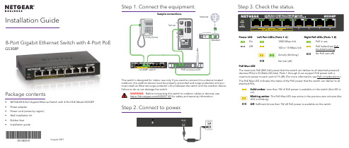
8-Port Gigabit Ethernet Switch with 4-Port PoEGS308PPackage contents• NETGEAR 8-Port Gigabit Ethernet Switch with 4-Port PoE Model GS308P • Power adapter• Power cord (varies by region)• Wall installation kit • Rubber feet •Installation guideAugust 2021This switch is designed for indoor use only. If you want to connect it to a device located outdoors, the outdoor device must be properly grounded and surge protected, and you must install an Ethernet surge protector inline between the switch and the outdoor device. Failure to do so can damage the switch.WARNING: Before connecting this switch to outdoor cables or devices, see https:///000057103 for safety and warranty information.Step 2. Connect to power.Step 3. Check the status.Power LED Left Port LEDs (Ports 1–4)Right PoE LEDs (Ports 1–8) On 1000 Mbps link PoE in useOff100 or 10 Mbps link PoE halted (see PoE troubleshooting) Activity (blinking) No PoE use (off)No link (off)PoE Max LEDThe maximum PoE (802.3af) power that the switch can deliver to all attached powered devices (PDs) is 53 Watts (W) total. Ports 1 through 4 can support PoE power with amaximum power to each port of 15.4W. (For more information, see PoE considerations.)The PoE Max LED indicates the status of the PoE power that the switch can deliver to all attached PDs.Solid amber : Less than 7W of PoE power is available on the switch (the LED is on).Blinking amber : The PoE Max LED was active in the previous two minutes (the LED is blinking).Off : Sufficient (more than 7W of) PoE power is available on the switch.Installation Guide© NETGEAR, Inc., NETGEAR and the NETGEAR Logo are trademarks of NETGEAR, Inc. Any non-NETGEAR trademarks are used for reference purposes only.NETGEAR, Inc.350 East Plumeria Drive San Jose, CA 95134, USANETGEAR INTERNATIONAL LTD Floor 1, Building 3University Technology Centre Curraheen Road, Cork, T12EF21, IrelandSupport and CommunityRegulatory and LegalSi ce produit est vendu au Canada, vous pouvez accéder à ce document en français canadien à https:///support/download/.(If this product is sold in Canada, you can access this document in Canadian French at https:///support/download/.)For regulatory compliance information including the EU Declaration of Conformity, visit https:///about/regulatory/.See the regulatory compliance document before connecting the power supply.For NETGEAR’s Privacy Policy, visit https:///about/privacy-policy/.By using this device, you are agreeing to NETGEAR’s Terms and Conditions athttps:///about/terms-and-conditions/. If you do not agree, return the device to your place of purchase within your return period.Do not use this device outdoors. The PoE source is intended for intra building connection only.Visit /support to get your questions answered and access the latest downloads.You can also check out our NETGEAR Community for helpful advice at .PoE Fault ConditionPossible SolutionA PoE-related short circuit occurred on the port.The problem is most likely with the attached PD. Check the condition of the PD or restart the PD bydisconnecting and reconnecting the PD.The PoE power demand of the PD exceeded the maximum level of 16.2W that the switch permits.The PoE current on the port exceeded the classification limit of the PD.The PoE voltage of the port is outside the range that the switch permits.Restart the switch to see if the condition resolves itself.PoE considerationsThe switch prioritizes the PoE (802.3af) power that it supplies in ascending port order (from port 1 to port 4), up to its total power budget (53 Watts). If the power requirements for the attached powered devices (PDs) exceed the total power budget of the switch, the PD on the highest numbered port is disabled to ensure that the PDs that are connected to the higher priority, lower numbered ports are supported first.Just because a PD is listed as an 802.3af PoE powered device does not necessarily mean that it requires the maximum power limit of the specification. Many PDs require less power, allowing all four PoE ports to be active simultaneously.The following table describes the PoE classes and switch allocations.Device Class StandardClass DescriptionMinimum Power Allocated to the Powered Device Range of Power Delivered to the Powered Device 0PoE and PoE+Default power (full)0.44W 0.44W–12.95W 1PoE and PoE+Very low power 4.0W 0.44W–3.84W 2PoE and PoE+Low power 7.0W 3.84W–6.49W 3PoE and PoE+Mid power 15.4W 6.49W–12.95W 4PoE+ onlyHigh power30.0W12.95W–25.5WPoE troubleshootingHere are some tips for correcting PoE problems that might occur:•Make sure that the PoE Max LED is off. If the PoE Max LED is solid amber, disconnect one or more PoE devices to prevent PoE oversubscription. Start by disconnecting the device from the highest numbered port.•Make sure that the Ethernet cables are plugged in correctly. For each powered device (PD) that is connected to the switch, the corresponding right port LED on the switch lights solid green. If the right port LED lights solid amber, a PoE fault occurred and PoE halted because of one of the conditions that are listed in the following table.SpecificationsSpecification DescriptionNetwork interface RJ-45 connector for 1000BASE-T, 100BASE-TX, or 10BASE-T Network cable Category 5 (Cat 5) or higher rated Ethernet cable Ports8Power adapter ****************Power consumption7.0W max. (no PoE)60W max (with PoE)PoE power budgetPorts 1-4: 15.4W maximum per PoE port, up to 53W total PoE power for the switch. For more information, see PoE considerations.Dimensions (W x D x H)6.2 in. x 4.0 in. x 1.1 in.(158 mm x 101 mm x 29 mm)Weight1.02 lb (0.46 kg)Operating temperature 32–104°F (0–40°C)Operating humidity 10%–90% relative humidity, noncondensingComplianceFCC Class A, CE Class A, VCCI Class A, RCM Class A, CCC, CB, KC。
X20(c)PS3300供电模块说明书
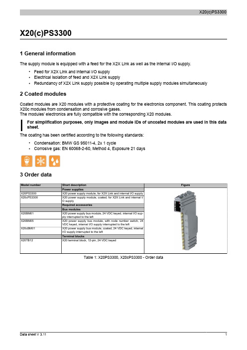
X20(c)PS33001 General informationThe supply module is equipped with a feed for the X2X Link as well as the internal I/O supply.•Feed for X2X Link and internal I/O supply•Electrical isolation of feed and X2X Link supply•Redundancy of X2X Link supply possible by operating multiple supply modules simultaneously2 Coated modulesCoated modules are X20 modules with a protective coating for the electronics component. This coating protects X20c modules from condensation and corrosive gases.The modules' electronics are fully compatible with the corresponding X20 modules.For simplification purposes, only images and module IDs of uncoated modules are used in this data sheet.The coating has been certified according to the following standards:•Condensation: BMW GS 95011-4, 2x 1 cycle•Corrosive gas: EN 60068-2-60, Method 4, Exposure 21 days3 Order dataTable 1: X20PS3300, X20cPS3300 - Order data4 Technical dataTable 2: X20PS3300, X20cPS3300 - Technical dataTable 2: X20PS3300, X20cPS3300 - Technical data1)The values specified here are maximum values. The exact calculation is also available for download as a data sheet with the other module documentation on the B&R website.2)Ta min.: 0°CTa max.: See environmental conditions3)In parallel operation, only 75% of the rated power can be assumed. It is important to make sure that all power supplies operating in parallel are switched on and off at the same time.5 LED status indicatorsFor a description of the various operating modes, see the section "re LEDs" in chapter 2 "System characteristics"of the X20 system user's manual.6 PinoutX 20 P S 3300Ir e7 Connection examplesWith 2 separate suppliesWith a supply and jumper8 DeratingThe rated output current for the supply is 7 W. Derating must be taken into consideration based on mounting orientation.Ambient temperature [°C]-2505740455055Installation position Horizontal VerticalN o m i n a l o u t p u t p o w e r [W ]4609 Register description9.1 General data pointsIn addition to the registers listed in the register description, the module also has other more general data points. These registers are not specific to the module but contain general information such as serial number and hardware version.These general data points are listed in the "General data points" section of chapter 4 "X20 system modules" in the X20 system user's manual.9.2 Function model 0 - Standard9.3 Function model 254 - Bus controllerThe module occupies 1 logical analog slot on CAN I/O.1)The offset specifies the position of the register within the CAN object.9.4 Module statusName:Module statusThe following voltage and current states of the module are monitored in this register:Bus supply current: A bus supply current of >2.3A is displayed as a warning.Bus supply voltage: A bus supply voltage of <4.7V is displayed as a warning.24 VDC I/O supply voltage:An I/O supply voltage of <20.4 V is displayed as a warning.Bit structure:9.5 Bus supply currentName:SupplyCurrentThis register displays the bus supply current measured at a resolution of 0.1 A.9.6 Bus supply voltageName:SupplyVoltageThis register displays the bus supply voltage measured at a resolution of 0.1 V.9.7 Minimum cycle timeThe minimum cycle time defines how far the bus cycle can be reduced without communication errors occurring. It should be noted that very fast cycles decrease the idle time available for handling monitoring, diagnostics and acyclic commands.9.8 Minimum I/O update timeThe minimum I/O update time defines how far the bus cycle can be reduced while still allowing an I/O update to take place in each cycle.。
迅达3300AP操作手册
迅达3300AP无机房3300AP(rel。
4版本),有四个按钮,分别是“ESC ↓↑OK”,四个键。
查故障:1、在标准显示状态下,按OK一次,显示”10”2、按↑键4次,显示”50"3、按OK键,显示”500”4、按↑键,显示"50 1”5、按0K键,就能查看最近的故障代码;按↓键,直到显示"E0****",再按↓显示"E1****",依次类推。
E0表示最新的故障。
6、清除故障方法:在显示”e*****"时,一直按住OK键约3秒,显示“——--——-”,说明清除故障成功。
限速器试验(刹车试验),注意:以下步骤前,先将107改为1(关闭称重),机房检修盒插上。
1、1、在标准显示状态下,按OK一次,显示102、按↑键一次,显示"20 0"3、按↑键一次,显示”20 1"4、按OK键5、显示”20 --”,同时电梯跑到最顶层,开门后,6、按↑键直到显示"20 75”,按OK键,同时显示”75 1”7、门开始关闭,之后显示”75 2"8、打机房检修,并按”下行键“,待电梯蜂鸣器长响后,按DBV键,刹车。
如果成功会显示”75 1”9、按ok键确认,显示”20 1",按↑键,显示”20 0",按OK键,显示”20“,再按”esc”退回返回主菜单。
10、刹车完后,机房检修拉起轿厢,(如果实在拉不起来,就搬走一部分砝码)11、最后,限速器开关复位操作:在主菜单上按”ok"键一次,显示”10",按OK键一次,显示”101",在按↑键直到显示125,按OK键一次,显示"125 0”,按↑键一次,显示”125 1”,按OK键一次,限速器开关就复位。
以上"*”是代表某个数字,显示屏上是不会显示的消防自学习消防板是装在基站带4个IO接口的板(SLCUX板),(仅适用于REL4。
8PT低压柜操作说明书

标准威胜电气8PT低压柜操作说明书文案目录一、开关柜主要性能参数 (3)二、操作规程 (5)1、开关柜的操作 (5)1.1断路器柜的操作 (5)1.2储能弹簧的储能 (8)2、抽屉柜的操作 (8)三、维护 (11)3.1 检查 (11)3.2 保养 (12)一、开关柜主要性能参数二、操作规程1、开关柜的操作1.1断路器柜的操作1.1.2抽出式断路器的准备往导向框架中装入断路器1、检查断路器位置指示器,确保显示的是DISCON,否则断路器将不能被放入。
2、抽出导轨。
3、将断路器放入导向框架中。
4、推到断开位置。
5、关闭柜门1.1.2断路器在导向框架中的位置示意图位置指示器电源回路辅助回路柜门安全挡板维护位置断开断开开关闭断开位置断开断开关关闭测试位置断开连接关关闭连接位置连接连接关开(1)辅助回路,(2)电源回路,(3)柜门,(4)安全挡板1.1.3松开摇查手柄/退出摇进手柄1、断开断路器2、前推摇进机构3、拉出手柄4、将控制杠杆抬起,并维持5、退出摇进机构1.1.4将断路器摇入连接位置1.1.5插入摇进手柄注意:不要将摇柄转到超出挡块的位置!否则会损坏摇进机构。
1.2储能弹簧的储能1.2.1手动储能F 手柄手柄力n 储能次数(1)弹簧已储能注意:储能时完全握住手柄,每次都要将手柄压到尽可能最底端!尽管感到手柄力会明显地增加,每次都要尽可能稳定地用力。
当储能结束后,手柄力即消失。
1.2.2通过电动储能操作机构储能在施加控制电压后,电动操作机构会自动启动。
当储能完毕后,电动机会自动停止转动。
在弹簧释能后(合闸操作后),电机会方始重新启动。
2、抽屉柜的操作2.1抽屉的操作8E、16E、24E抽屉单元与8E/4、8E/2抽屉单元不同,抽屉的操作手柄和主开关手柄分开,操作手柄具有四个位置,各个位置设计有电气和机械联锁。
转动该手柄,即可对抽屉单元进行相应的操作。
操作手柄上可加挂锁(最多加三把),以避免抽屉被误抽插或误合开关。
LT-3300 系列 安装指南说明书
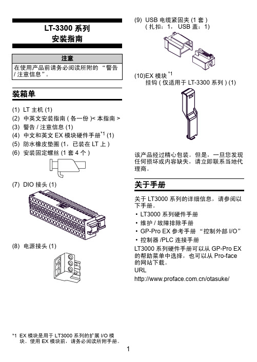
LT-3300系列安装指南装箱单(1)LT 主机(1)(2)中英文安装指南(各一份)<本指南>(3)警告/注意信息(1)(4)中文和英文EX 模块硬件手册*1(1)(5)防水橡皮垫圈(1,已装在LT 上)(6)安装固定螺丝(1套4个)(7)(8)电源接头(1)(9)USB 电缆紧固夹(1套)((10)EX 模块挂钩(仅适用于LT-3300系列) (1)该产品经过精心包装。
但是,一旦您发现任何损坏或内容缺失,请立即联系当地代理商。
关于手册关于LT3000系列的详细信息,请参阅以下手册。
•LT3000系列硬件手册•维护/故障排除手册•GP-Pro EX 参考手册“控制外部I/O ”•控制器/PLC 连接手册LT3000系列硬件手册可以从GP-Pro EX 的帮助菜单中选择,也可以从Pro-face 的网站下载。
URL/otasuke/注意在使用产品前请务必阅读所附的“警告/注意信息”。
*1EX 模块是用于LT3000系列的扩展I/O 模块。
使用EX 模块前,请务必阅读所附手册。
部件名称和功能名称描述A 状态指示灯B DIO 接口(DIO)连接外部I/O 设备的接口C 辅助模块接口/扩展模块(EXT2)用于连接附加模块(通讯功能等)。
D EX 模块接口(EXT1)用于连接Pro-face 制造的EX 模块E 电源接头F 以太网接口(10BASE-T/100BASE-TX)使用RJ-45型Modular Jack 接头(8孔)。
G USB 主机接口(USB)1接口符合USB1.1。
(TYPE-A 连接)电源电压: DC5V ± 5%输出电流: 500mA (最大)最大通讯距离是5米。
H 串口(COM1)D-Sub 9针凸型接头。
通讯方式(RS-232C/RS-422/RS-485)通过软件来切换。
正视图后视图底视图右视图颜色指示灯操作模式(绘图)程序执行模式(启用逻辑程序时)绿ON 离线运行中运行闪烁运行中停止红ON 上电时闪烁运行中严重错误橙ON 背光灯烧毁闪烁软件启动过程中一般规格电气规格环境规格电源输入电压DC24V额定电压DC19.2~28.8V 允许失电3ms 以下功耗27W 以下瞬时电流30A 以下绝缘强度AC1000V 20mA 时1分钟(电源端与FG 端子之间)绝缘电阻DC500V 10M Ω以上(电源端和FG 端子之间)物理工作环境温度0~+50°C *1*1如果在温度为40°C 以上的环境中使用并持续一段时间,人机界面屏幕对比度会有所下降。
EX3300 交换机

Junos操作系统 EX3300与其它瞻博网络EX系列以太网交换机、瞻博网络路由 器和瞻博网络SRX系列业务网关一样,采用了相同的Junos操 作系统。利用一个通用操作系统,瞻博网络能够在所有产品中 一致地实施和运行控制平面特性。为了保持这种一致性,Junos 操作系统严格遵守开发流程,使用单一源代码,坚持每个季度 推出一个新版本,并采用高度可用的模块化架构,能够有效地 防止组件故障对整个系统产生影响。
这些特性对于软件实现其核心价值至关重要,它们支持所有安 装Junos操作系统的产品可以同时升级到相同的软件版本。所有 的功能都经过完全的回归测试,能够确保每个新版本在功能上 都是前一个版本的超集。用户可以完全放心地部署软件,因为 以前版本的所有功能都将被保留,而且照常运行。
接入层
10GbE链路, 将EX3300连接 到汇聚/核心层
10/100/1000 端口总数
上行链路
24 48 48 24 PoE+ 48 PoE+ 24
4个双模式
10GbE/GbE SFP+/SFP
端口
风冷
前进后向 前进后向 后进前向 前进后向 前进后向 前进后向
电源类型
AC AC AC AC AC DC
POE+ 功率预算
(W)
3300八组合说明书

7.5 再次按下向右键进入画面 4,显示如下信息:
4
参数整定
项目
参数名称
1 额定电流
2 速断电流倍数
3 运行方式
4 程控前级回路
5 程控自动延时
6 另一低速回路/程控后级回路
7 程控停车延时
8 本机高速回路
9 第一低速回路
10 双速切换时间
接触器 #1 数值
A
0,0s 0,0s
0,0s
在此画面中进行参数设置:按向下或向上键选来选定 1~10 中任意一项;设置每一 项中的参数时,需按确认+向下或向上两键来实现,且操作时先按下确认 2 秒,接着 再按下向下或向上 键来整定,按确认+向下键数值递增,按确认+向上键数值递减。 各回路所需设定参数及基本含义如下表:
2-程控
当本回路为程控运行首回
路时选本回路序号
5 程控起动延时 程控工况时,前级起动 0~40.0S 后,本回路须延时起动 时间
当本回路为程控运行首回 路时选为 1
6 程控后级回路 程控工况时,其后一级 1~6 运行回路序号
另一低速回路 双机双速控制时,设定 1、3、5 另一电机的低速回路
另一高速回路 双 机 双 速 控 制 时 设 定 2、4、6 另一电机的高速回路
7.4 再次按下向右键进入画面 3,显示如下信息:
故障显示 3 漏电闭锁 短路 过载 断相 过压 欠压 通讯 其它 #1 #2 #3 #4 #5 #6 #7 #8 在此画面中,当发生故障后可以显示#1~#8 回路是哪种故障方式。故障排除后除
-6-
“短路”和“其它”两种故障方式需按复位键返回画面 1 运行状态,其余故障方式排除 后将自动返回画面 1 运行状态。 注“其它”故障为上述故障之外的故障。
- 1、下载文档前请自行甄别文档内容的完整性,平台不提供额外的编辑、内容补充、找答案等附加服务。
- 2、"仅部分预览"的文档,不可在线预览部分如存在完整性等问题,可反馈申请退款(可完整预览的文档不适用该条件!)。
- 3、如文档侵犯您的权益,请联系客服反馈,我们会尽快为您处理(人工客服工作时间:9:00-18:30)。
8-PORT 10/100/1000M SWITCH WITH 8-PORT 803.2at POE
To fulfill the demand of PoE for network applications with Gigabit speed transmission, the ONV PoE Gigabit Ethernet Switch -POE33008P-at is an ideal solution. Each 10/100/1000Mbps port of POE33008P-at features IEEE 802.3at Power over Ethernet (PoE) that combines up to 220 Watts power output and data per port over one Cat.5E / 6 Ethernet cable, with totally 220 Watts PoE budget on whole system
》It is designed specifically to satisfy the growing demand of higher power consuming network PD (powered devices) such as PTZ (Pan, Tilt & Zoom) / Speed Dome network cameras, multi- channel (802.11a / b / g / n) wireless LAN access points and other network devices by providing double PoE power than conventional 802.3af PoE currently
Product features
◆IEEE 802.3at power on up to 8 ports
◆Supply power to wireless access points and surveillance cameras over Cat-5 cabling
◆8 10/100/1000 Mbps Ports with AutoUplink™
◆Supports PoE power up to 25.5W for each PoE port
◆Supports PoE power up to 210W for all PoE ports
◆Supports PoE IEEE 802.3at compliant PDs
◆Hardware based 10/100/1000Mbps Auto-Negotiation and Auto MDI/MDI-X
◆8K entry MAC address table of the PoE Switch POE33008P-at with auto-learning and auto-aging ◆LED indicators for monitoring power, link, activity and speed
◆External power adapter supply
Target Industries
◆HD monitor transmission and power supply
◆Wireless AP layout transmission and power supply
◆Network telephone transmission , intelligent house and home
system
◆Intelligent transportation supervisory system(ITS)
◆High-speed Way supervisory/Tele-Communication System
◆Security protection system, TV medical treatment
◆Long-distance Muti-media Schooling, Campus monitoring
◆Long-distance broadcast television transmission system
◆High-building Security Protection, Military Tele-Com projects
Specifications
Order Information:
Product:POE33008P-AT
Type:8-PORT 10/100/1000M SWITCH WITH 8-PORT 802.3at POE,IEEE 802.3at,PoE Power Output:
25.5Watts,PoE Budget:210Watts
Power Pin Assignment:Data provided over pairs over 1/2and 3/6 ,Power over spare pairs4/5(+) and 7/8 (-) Accessories in the package:
Product size(mm):279 x 195 x 44mm
A.POE power supply port
B. AC 220V,50Hz input port
Application
Department / Workgroup PoE Switch:
Providing 8-Port 802.3at PoE in-line power interfaces, the POE33008P-AT-at can easily build a power centrally-controlled IP phone system, IP Camera system and Wireless AP group for the enterprise. For instance, up to 8 PoE IP cameras can be installed around the corner in the company for surveillance demands or up to 8 PoE Wireless AP to build a wireless roaming environment in the office. Without the power-socket limitation, the
Switch makes the installation of cameras or Wireless AP more easily and efficiently.。