AL-7480B升级版用户指南
AL-7480-8B报警主机安装指南

d开1号锁防区: 一直处于激活状态,不论撤布防与否,只要一触发就操作输出1。 e an ---- 9 ---
fo AL-7480-8B 报警主机安装指南 od 开2号锁防区: 一直处于激活状态,不论撤布防与否,只要一触发就操作输出2。
go 旁路防区: 若某防区允许旁路,用户留守布防后,该防区触发无效。
e and A ---- 1 ---
ood fo AL-7480-8B 报警主机安装指南
一、概述
re g AL-7480-8B 系列报警主机具有很强的实用性,被广泛地应用在小区、厂矿院校、以及办公大楼等各类 a 大型安保系统中,可实现不同方式的联网报警,根据用户需求,有多种不同选择。
eing 1. 系列产品描述
e 1. AL-7480-8B 支持的防区类型及说明 ‥‥‥‥‥‥‥‥‥‥‥‥‥‥‥‥‥‥ 9 b 2. AL-7480-8B 防区报警时间跟随属性说明 ‥‥‥‥‥‥‥‥‥‥‥‥‥‥‥‥ 10 ir 3. AL-7480-8B 无线自学防区和遥控器 ‥‥‥‥‥‥‥‥‥‥‥‥‥‥‥‥‥‥ 10 the 4. 交叉防区 ‥‥‥‥‥‥‥‥‥‥‥‥‥‥‥‥‥‥‥‥‥‥‥‥‥‥‥‥‥ 11
AL-7480-8B 系列主要功能及性能介绍
ir b 联网类型:分别支持总线பைடு நூலகம் IP; the 显示模式:分别有 16 个 LED 或汉字 LCD。
in 2. 主要功能
gs 支持 8 个防区,有线无线兼容,防区号为 1-8。另外 9-16 防区可以外扩 8 个独立无线防区 in 8 个有线防区通过 4 个接口输入,每个有线接口最多可以接 2 个防区,通过两个不同阻值的电阻
ood fo AL-7480-8B 报警主机安装指南
AL-2010S操作说明

AL-2010S操作说明1.1 第一步点击“获取序列号”文件进入以下界面点击“获取”就会生成的一组数字,请将该组数字回馈给我公司,将会给一个软件启动的序列号。
1.2第二步点击“” ,出现以下界面输入序列号就可以进入软件。
(第一次使用时才需要)1.3 第三步点击“” ,运行程序该程序。
进入以下界面:输入系统管理员初始名称:ADMIN系统管理员初始密码:ADMIN初始安装的系统中拥有系统管理员用户,具有所有权限,其他用户的增加及权限设置有系统管理员管理注意:第一次进入后应更改此口令。
2.1 软件用户界面用户界面主要包括主显示界面、系统菜单、工具栏。
主显示界面主要显示报警板,用户/防区地图,用户防区资料,报警历史记录等数据,但这些内容不能同时显示。
弹出式窗口主要显示报警处理界面,主机参数设置,系统参数设置等内容,允许同时弹出多个窗口,这些窗口覆盖主显示界面。
AL-2010S所有功能全部在系统菜单中有相应选项,常用功能在工具栏中列出。
2.2 基本操作AL-2010S所有功能可以通过系统菜单实现,系统菜单如下:3.1 进入参数设置进入主菜单“配置中心”—“参数设置”,对用户本身的基本信息和其他系统参数进行设置。
参数设置主界面3.2 通过串口或TCP/IP连接的中心设备3.2.1修改中心设备编号进入“参数设置”—“全局配置”串口连接:修改中心设备编号为“1-10”,“1-10”号中心设备可通过串口连接多台报警主机和通讯机(AL-7480B、AL-3280等报警主机系列);1-10分别代表的电脑上的每个串口。
TCP/IP连接:修改中心设备编号为“11”,“11”号中心设备可通过网络连接多台报警主机和通讯机注:1、在首次设置时出现“Warning”提示,可直接确定2、在已经设置好相应中心设备下的相关参数后,修改该编号,将会删除原来该中心设备下的所有信息。
3.2.2 通讯参数设置进入以下界面:此UDP端口(也就是本机端口)必须与网络(TCP/IP)主机的UDP端口一致。
Dell Latitude 7480 Product Compliance Datasheet说明书

Product Compliance DatasheetMARKETING NAME…………Latitude 7480/Latitude 7480-01REGULATORY MODEL (73)REGULATORY TYPE……….P73G001EMC EMISSIONS CLASS….BEFFECTIVE DATE……December 28, 2016Table of contentsI.Statement of Compliance (2)II.Global Environmental Information (2)III.Power Cords and User Documentation (3)IV.Trade (Import/Export) Compliance Data (3)V.Product Dimensions and Weight (3)VI.Performance Data (3)VII.Product Materials Information (3)VIII.P ackaging (5)IX.Batteries (5)X.Design for Environment (6)XI.Recycling / End-of-Life Service Information (6)XII.Helpful Links (6)A Appendix A: ErP Lot 3 Product Energy Consumption Information (7)B Appendix B: ErP Lot 26 Network Standby Energy Consumption Information (9)1 Product Compliance Datasheet | ENV0023 | A12I. Statement of ComplianceThis equipment has been determined to be compliant with the applicable standards, regulations, anddirectives for the countries where the equipment is marketed. The equipment is affixed with regulatorymarking and text as necessary for the country/agency. Dell manufacturers and markets MultimediaEquipment (MME), Information Technology Equipment (ITE), Audio Visual Equipment (A/V), Industrial,Scientific, Medical Equipment (ISM) or combinations of these. Generally, equipment Safety and EMCcompliance is based on International IEC and CISPR standards and their national equivalent along withnational standards for Radio (wireless), and Energy. Dell products have been verified to comply with the EURoHS Directive 2011/65/EU. Dell equipment does not contain any of the restricted substances inconcentrations and applications not permitted by the RoHS Directive. EMC Emissions Class refers to one ofthe following use environments:•EMC Class B equipment is intended for use in residential/domestic environments but may also be used in nonresidential/non-domestic environments.•EMC Class A equipment is intended for use in non-residential/non-domestic environments. Class Aequipment may also be utilized in residential/domestic environments but may cause interference and requirethe user to take adequate corrective measures.For Safety and EMC compliance, this equipment has been assigned a unique regulatory model andregulatory type that is imprinted on the equipment regulatory labeling to provide traceability to the regulatoryapprovals noted on this datasheet. This datasheet applies to any equipment that utilizes the assignedregulatory model and type including marketing names other than those listed on this datasheet. ErPcompliance is tied to the CE mark. REACH (Registration, Evaluation, Authorization and Restriction ofChemicals, 1907/2006) is the European Union’s (EU) chemical substances regulatory framework. Dellcomplies with the REACH directive. For information on SVHC (Substances of Very High Concern), see/REACH. Compliance documentation, such as certification or Declaration of Compliance for theequipment is available upon request to ***************************. Please include equipment identifierssuch as marketing name, regulatory model, regulatory type and country that compliance information isneeded in request.II. Global Environmental Information2 Product Compliance Datasheet | ENV0023 | A12III. Power Cords and User DocumentationDell products are provided with the power cord and user documentation suitable for the intended country of delivery. Products that are relocated to other countries should use nationally certified power cords and plugs to ensure safe operation of the product. Contact Dell to determine if alternate power cords or userdocumentation in other languages is available for your market.IV. Trade (Import/Export) Compliance DataFor any questions related to importing & exporting classification of Dell products, please obtain information from the following link: /import_export_compliance or send request to*****************************.V. Product Dimensions and WeightVI. Performance DataErP Lot 3 & Lot 26 information is located in section XIV Appendix AFor additional information on ENERGY STAR models refer to the following databases:/en-us/work/learn/power-and-cooling-energy-starUSA: https:///productfinder/EU: /db-currentlists.htmThe battery[ies] in this product cannot be easily replaced by users themselves.VII. Product Materials InformationInformation on Dell’s material use is available here.Dell’s Restricted Material for Use guidance document is available here.∙The case material is, cover: >PC-GF50FR(40)< , cover-CF: >EP-(CF70)FR(40)<; >PC-(CF+GF)64FR(40)< , log up: >PC-GF50FR(40)< , Bezel: >TPC-ET, PC+ABS FR(40)<∙This product contains 7% post-consumer recycled plastic/closed loop recycled plastics(Measured as a percentage of total amount of plastic (by weight) in the product as per guidance in EPEAT standard as applies to plastics parts)4 Product Compliance Datasheet | ENV0023 | A12Flame Retardants Used in MotherboardMercury Information∙ RoHS and REACH declaration - see product material information section at:/environmental_information∙ Products MSDS (Material Safety Data Sheets):1 Mechanical plastic part: plastic parts that do not internally carry an electrical signal such as housings, brackets, bezels, latches, etc. that form the basicstructure of the product and/or have mechanical functions. Plastic parts such as fans, connectors, printer fuser assemblies, etc. are not considered“mechanical plastic parts” in the context of this specification. Plastics parts do not contain no more than 0,1% weight (1000 ppm) bromine and 0,1% weight (1000 ppm) chlorine attributable to brominated flame retardants, chlorinated flame retardants, and polyvinyl chloride (Per Dell Spec ENV0424)2 Dell will adopt the BFR/CFR/PVC-free definition as set forth in the "iNEMI Position Statement on the Definition of 'Low-Halogen' Electronics (BFR/CFR/PVC-Free)." Plastic parts contain <1000 ppm (0.1 percent) of bromine (if the Br source is from BFRs) and <1000 ppm (0.1 percent) of chlorine if the Cl source is from CFRs, PVC or PVC copolymers. All printed circuit board (PCB) and substrate laminates contain bromine/chlorine totaling less than 1,500 ppm (0.15 percent), with maximum chlorine of 900 ppm (0.09 percent) and maximum bromine of 900 ppm (0.09 percent)Batteries: Battery MSDS Documentation and DeclarationPrinter Toner and Ink: MSDS DocumentationVIII. PackagingInformation on Dell’s sustainable packaging effort available here.IX. Batteries3 Non-wood, biobased material may include, but is not limited to: bagasse, bamboo, mushroom, straw, agricultural waste or byproduct. * Recycled content in packaging material is supplier dependent.X. Design for EnvironmentDell systems are, when applicable, designed for easy assembly, disassembly, and servicing.For more information on product Recyclability please visit /environmental_informationXI. Recycling / End-of-Life Service InformationTake back and recycling services are offered for this product in certain countries. If you want to dispose ofsystem components, please visit /recyclingworldwide and select the relevant country. XII. Helpful Links∙Environmental Policy/sites/content/corporate/corp-comm/en/Documents/dell-global-environmental-policy.pdf ∙Environment Website/environmental_information∙Corporate Sustainability Report/Learn/us/en/uscorp1/report?c=us&l=en&s=corp&delphi:gr=true∙ISO 14001 Certification/sites/content/corporate/corp-comm/en/Documents/dell-iso14001-worldwide.pdf ∙Materials Restricted for Use/downloads/global/corporate/environ/restricted_materials_guid.pdf ∙Chemical Use Policy/sites/doccontent/corporate/environment/en/Documents/chemical-use-policy.pdf ∙Product Carbon Footprint/us/en/corp/d/corp-comm/environment_carbon_footprint_products ∙RoHS Compliance/rohsinfo∙REACH Compliance/REACH∙Recycling Information/recycling∙Supplier Responsibility/us/en/corp/d/corp-comm/standards-for-suppliers.aspx6 Product Compliance Datasheet | ENV0023 | A12A Appendix A: ErP Lot 3 Product Energy ConsumptionInformationErP Lot 3 (EU No 617/2013)The ErP Lot 3 regulation includes requirements for certain product specific information to be provided by the manufacturer. This is applicable to Desktops, Integrated Desktops (All-in-One), Notebooks, Tablets, Slates, Notebook Thin Clients, Desktop Thin Clients, Workstations, Mobile Workstations, Computer Servers, and Small Scale Servers.ErP Lot 3 provides certain exclusions based upon product type, screen size, and/or the amount of power consumed in idle mode. Product energy and acoustic information might be reported for products that are out of scope of ErP Lot 3 for informational purposes only.* Energy Consumption results are based solely upon the laboratory testing of the System Configuration listed above. Energy consumption is tested at 230 Volts / 50 Hz.Energy Consumption*Energy efficiency benefits the environment and lowers the total cost of equipment ownership by reducing power consumption. Dell offers energy calculators that help estimate power needs, potential emissions avoidance and potential cost savings. Click here for Dell’s Client Energy Savings Calculator, Data Center Capacity Planner, and Monitor Power Savings Calculator. Information on Energy Efficiency is available here* This document is informational only and reflects laboratory performance. Your product may perform differently, depending on the software, components and peripherals you ordered. Accordingly, the customer should not rely upon this information in making decisions about electrical tolerances or otherwise. No warranty as to accuracy or completeness is expressed or implied.For more details visit /environmental_information8 Product Compliance Datasheet | ENV0023 | A12B Appendix B: ErP Lot 26 Network Standby EnergyConsumption InformationErP Lot 26 (EU No 801/2013)The ErP Lot 26 regulation includes Network Standby power requirements to be provided by the manufacturer. This is applicable to multiple product categories. If no information is reported, it’s assumed it is out of scope of ErP Lot 26.。
(完整版)AL-7480-8B报警主机安装指南
目录一、概述‥‥‥‥‥‥‥‥‥‥‥‥‥‥‥‥‥‥‥‥‥‥‥‥‥‥‥‥‥‥‥‥‥2二、安装‥‥‥‥‥‥‥‥‥‥‥‥‥‥‥‥‥‥‥‥‥‥‥‥‥‥‥‥‥‥‥‥‥4三、系统配置及连线说明‥‥‥‥‥‥‥‥‥‥‥‥‥‥‥‥‥‥‥‥‥‥‥‥‥‥4四、防区类型和属性‥‥‥‥‥‥‥‥‥‥‥‥‥‥‥‥‥‥‥‥‥‥‥‥‥‥‥‥91.AL—7480—8B支持的防区类型及说明‥‥‥‥‥‥‥‥‥‥‥‥‥‥‥‥‥‥92.AL-7480—8B防区报警时间跟随属性说明‥‥‥‥‥‥‥‥‥‥‥‥‥‥‥‥ 103.AL-7480-8B无线自学防区和遥控器‥‥‥‥‥‥‥‥‥‥‥‥‥‥‥‥‥‥104.交叉防区‥‥‥‥‥‥‥‥‥‥‥‥‥‥‥‥‥‥‥‥‥‥‥‥‥‥‥‥‥11五、AL-7480—8B的键盘操作说明‥‥‥‥‥‥‥‥‥‥‥‥‥‥‥‥‥‥‥‥‥‥‥121。
密码说明‥‥‥‥‥‥‥‥‥‥‥‥‥‥‥‥‥‥‥‥‥‥‥‥‥‥‥‥‥122. 用户操作指南‥‥‥‥‥‥‥‥‥‥‥‥‥‥‥‥‥‥‥‥‥‥‥‥‥‥‥13六、AL—7480—8B编程说明‥‥‥‥‥‥‥‥‥‥‥‥‥‥‥‥‥‥‥‥‥‥‥‥‥‥16编程举例‥‥‥‥‥‥‥‥‥‥‥‥‥‥‥‥‥‥‥‥‥‥‥‥‥‥‥‥‥‥‥18编码功能列表‥‥‥‥‥‥‥‥‥‥‥‥‥‥‥‥‥‥‥‥‥‥‥‥‥‥‥‥‥21地址编码表‥‥‥‥‥‥‥‥‥‥‥‥‥‥‥‥‥‥‥‥‥‥‥‥‥‥‥‥‥‥29一、概述AL—7480—8B系列报警主机具有很强的实用性,被广泛地应用在小区、厂矿院校、以及办公大楼等各类大型安保系统中,可实现不同方式的联网报警,根据用户需求,有多种不同选择。
AL-7480—8B系列主要功能及性能介绍1。
系列产品描述联网类型:分别支持总线和IP;显示模式:分别有16个LED或汉字LCD.2. 主要功能●支持8个防区,有线无线兼容,防区号为 1-8.另外9—16防区可以外扩8个独立无线防区●8个有线防区通过4个接口输入,每个有线接口最多可以接2个防区,通过两个不同阻值的电阻来区分防区。
艾礼安AL-7480(II)说明书
AL-7480用户使用手册深圳艾礼安安防设备有限公司说明AL-7480通讯主机系统是具有很强的使用性被广泛地应用在小区住家及周界报警系统大楼安保系统、以及工厂学校仓储等各类大型安保系统可实现计算机管理并方便地与其它系统集成。
AL-7480主要功能及性能指标一. 主要功能●最多可接2042个防区:自身带有2个有线, 通过通讯接口1可以外接最多127个总线扩展模块或者总线主机, 通过通讯接口2可以外接最多128个总线扩展模块或者总线主机,每个扩展输入设备最多可接8个的防区●所有防区以分区的形式管理,最多有2x128个分区:自身带有的2个防区,为第1-127分区;外接的接警设备(报警模块或主机)从第00分区开始,按照地址码的顺序,每一个设备为1个独立分区。
每个键盘可以拥有其中的1个或多个分区,各键盘分别对自己的所管辖的所有分区独立同时进行布防、撤防等操作;主键盘可以对单个分区、防区独立进行布防、撤防操作●可最多接入15个键盘,独立操作,汉字界面。
其中1个主键盘、14个从键盘通讯口1和通讯口2分别最多可接7个从键盘),通过主键盘编程可以让任意键盘跟随所有报警并显示报警信息。
●设备、防区名称汉字任意更改,电脑配置,每个设备、防区最多支持7个汉字●挂在通讯总线上的设备都可以带有1-64个输出,其中报警模块最多带有1个输出,联动输出设备最多可带64个输出。
每个防区可以联动最多3个输出,联动包括:防区报警联动、防区布撤防联动、防区异常联动。
可以达到电子地图、DVR报警输入、就地报警等功能●有3个密码权限,包括管理、编程、操作●通过局域网(TCP/IP)可实现与中心计算机连接,最多支持两个中心(必须外加IP800接口模块)●可通过电话线与报警中心通过Contact ID协议连接,并可电话通知用户●通过键盘密码、遥控器、中心计算机、电话进行撤/布防●通过管理员密码撤布防,同时对所有键盘进行撤布防;对主键盘(键盘地址位0,挂接在键盘总线上)的撤布防,通过编程跟随设置,可以让其中一个从键盘或所有从键盘同时布撤防。
fi-7480 fi-7460 消耗品替换和清洁指南说明书
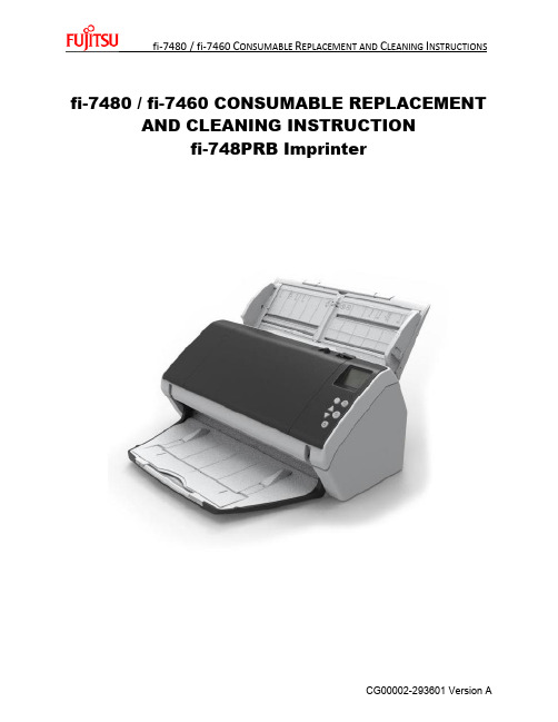
fi-7480 / fi-7460 CONSUMABLE REPLACEMENT AND CLEANING INSTRUCTIONfi-748PRB ImprinterConsumable Replacement ProcedurePick Rollers Qty 2 Brake Roller Qty 1Brake Roller Assembly (with shaft) Pick Roller Assembly (with shaft)REPLACING THE BRAKE ROLLERThe Glass inside the ADF becomes very hot when the scanner is being used. Before you replace the consumables, turn off the power, unplug the power cable, and let cool for 15 minutes1. Remove all documents from the ADF paper chute2. Open the ADFWhen the ADF is open, it might close accidentally. Use caution when the ADF is open.3. Remove the Brake Roller Shaft Assemblya. Hold both Ends of the cover and open it in the direction of the arrow.b. Lift the right side of the roller. Pull out the shaft form the slot on the left4. Remove the brake roller from the Brake Roller Shaft Assembly5. Attach a new brake roller on the Brake Roller Shaft Assemblya. Insert the Protrusion on the Brake Roller Shaft Assembly into the slot on the brake roller.6. Attach the Brake Roller Shaft Assemblya. Insert the left end of the Brake Roller Shaft Assembly into the hole in accordance with thehole shape and then attack the right side of the shaftb. Close the cover7. Close the ADF8. Reset the Brake Roller CounterReplacing the Pick RollerThe Glass inside the ADF becomes very hot when the scanner is being used. Before you replace the consumables, turn off the power, unplug the power cable, and let cool for 15 minutes1. Remove the documents from the ADF paper Chute2. Remove the ADF Paper Chute3. Open the ADF - Open the ADF by pressing the ADF Open Lever and Pull the ADF towardsthe front of the scanner in the direction of the arrow shown in the pictures below.When the ADF is open, it might close accidentally. Use caution when the ADF is open.4. Remove the Pick Shaft Assemblya. Open the sheet guide by lifting the tabsb. Rotate the bushing on the Pick Shaft Assembly in the direction of the arrowc. Remove the Pick Shaft Assemblyd. Hold and lift the bushing in the direction of the arrow below (1)e. Pull the bushing up in the direction of the arrow below (2)f. Lift the Pick Shaft Assembly up in the direction of the arrow below (3)*Be careful not to touch the gear near the bushing on the shaft as it contains grease*5. Remove the two (2) pick rollers from the Pick Shaft Assembly on at a time.a. Pull out one of the pick rollers from the as you press the retaining clip.b. Pull out the other pick roller from the Pick shaft Assy as you press the retaining clip6.Attach two (2) new pick rollers on the Pick shaft Assembly one at a timea.Insert the retaining clip of the pick roller into the slotb.Insert the retaining clip of the other pick roller into the slotCheck that the pick rollers are attached properly. Otherwise, it may cause feedingerrors such as paper jams. Make sure to insert the pick rollers until they lock in place.7.Reinstall the Pick Shaft Assemblya.Insert the left end of the shaft into the slot and lower the other end gradually.b.Rotate the bushing on the pick shaft in the direction of the arrow belowc.Close the sheet guide. Make sure that both ends of the sheet guide are locked firmly.Confirm that the pick Shaft Assembly is installed properlyOtherwise, it may cause feeding errors such as paper jams8.Close the ADF9.Attach the ADF paper Chute10.Reset the pick Roller CounterIf you find the counts are close to or over 200,000 and cleaning doesn’tresolve a feeding issue it might be time to replace the consumables.1. Checking and resetting the Sheet Counters After Consumable Replacementa. Start up the Software Operation Panel (SOP)b. From the listing on the left, Select “Device Setting”c. Resetting the sheet countersd. Click the “Clear(2) button for “Brake Roller” -> the counter is reset to “0”e. Click the “Clear(3) button for “Pick Roller” -> the counter is reset to “0”If the glass surface or the rollers are still dirty after they are wiped with a dry cloth, use a cloth moistened with 90% or higher Isopropyl Alcohol. As the scanner continues to feed documents, paper dust will accumulate inside the ADF and it may cause scanning errors. Cleaning should be performed approximately every 5,000 sheers scanned.∙The glass inside the ADF can be very hot when the scanner is being used. Before you start cleaning the inside, make sure to turn off the power, unplug the power cable and wait at least 15 minutes for the inside of the ADF to cool down.Note -∙Do not use water or mild detergent to clean the ADF∙When using Isopropyl Alcohol, use small quantities. Excessive amount of alcohol may take a while to dry∙Do not us alcohol on the plastic frame. It may deteriorate the frameCLEANING INSTRUCTIONSThe following table shows the specifications of consumables and their standard replacement cycle. It is recommended that you stock extra consumables before the ones in the scanner reach the end of their service life. The consumables must be replaced periodically. You can check the number of scanned pages for the Brake roller unit and the Pick roller unit by referring to each counter on this scanner.Description Qty Life Fujitsu P/NPick Rollers (2) 1 200,000 PA03710-0001Brake Roller 1 200,000 PA03670-0002Note: Replacement Cycles are estimated guidelines established by testing with A4/Letter sized wood free and wood based 17 lb. paper. NCR or Carbonless paper has chemical composition which damages the pad and the pick roller. Cleaning of the consumables will be required more frequently to avoid feed problems. Consumable life will be reduced if NCR or Carbonless paper is scanned.C LEANING THE S CANNERThe Scanners Automatic Document Feeder (ADF) should be cleaned at least every 5000 pages. This is very dependent on the types of paper being scanner, when scanning documents with toner that has not fused will or have ink, the scanner may require more frequent cleaning.2. Turn off the scanner and wait for at least 15 minutes3. Open the ADF by pressing the ADF Open Lever and Pull the ADF towards the front of thescanner in the direction of the arrow shown in the pictures below.When the ADF is open, it might close accidentally. Use caution when the ADF is open.4. Clean the following parts with a dry lint free cloth or moistened with F1[1] Cleaning the Brake Roller (x2)a. Remove the Brake Roller (Refer to )b. Gently wipe off any dirt or dust along the grooves, taking care not to damage the rollersurface.[2] Cleaning the Pick Roller (x2)Gently wipe off any dirt along the grooves as you rotate the roller manually, taking care not to damage the roller surface. Make sure that it is wiped properly because black residue on the roller will affect the feeding performance.[3] Cleaning the Plastic Idler Roller (x4)Gently wipe off any dirt or dust on the roller, taking care not to damage the roller surface.Make sure that it is wiped properly because black residue on the roller will affect the feeding performance. When wiping the roller, be careful not to damage the sponge that is attached to the middle of the plastic idler roller.[4] Cleaning the Glass (x2)Gently wipe off any dirt or dust on surface of the glass sections[5] Ultrasonic Senor (x2)See pictures below[6] Document Sensor (x8)Gently wipe the dirt and dust off the surface of the ultrasonic/ document sensorsIf it is difficult to clean, use a cotton swab[7] Feed Roller (x2)[8] Eject Roller (x2)To Clean the Feed/Eject rollers, turn the rollers in the machine to clean all of theroller5. Checking and resetting the Sheet Counters After Cleaninga. Start up the Software Operation Panel (SOP)b. From the listing on the left, Select “Device Setting”1. C hecking when to perform Cleaning2. C heck After Cleaning3. T his counter turns yellow when the page count after cleaning reaches 100% ofthe value specified in “Cleaning Cycle” (Scanner cleaning cycle setting) inSoftware Operation Panel.c. Resetting the sheet countersd. Click the “Clear(1) button for “After Cleaning” -> the counter is reset to “0”The following message may appear while the scanner is in use. In this case check the message and perform cleaning.Replacing the Print Cartridge (Consumable) for the ImprinterThe Print Cartridge is replaced approx. 4,000,000 characters depending on the font or Every 6 months Check the expiration date on the package to make sure it hasn’t expiredo The install-by date is printed on the package of the print cartridge. The Cartridge needs to be installed by the date specifiedo The cartridge can be used for six months from the time the package is opened.Notice – when installing the print cartridge, make sure it is installed properly1. Turn of the Scanner2. Place your hand in the middle part of the print cartridge cover and open it as shown below.3. When using the imprinter for the first time, remove the tape on the print cartridge holder.4. Lift the print cartridge holder by pinching the lever with your fingers as shown below.5. If there is a print cartridge already installed, remove the print cartridge.6. When replacing the print cartridge, prepare a new print cartridge as shown below. Notice – Do not touch the metal part of the print cartridge or put the tape back on again.7. Put the print cartridge into the holder with its tabs pointing to the right.Notice – be careful not to let the print cartridge catch the print circuit film8. Lower the print cartridge holder gently until it locks in place.9. Place the print cartridge within the printing area.a. Hold the print cartridge as shown below and slide it left and right to place it wherethe document will pass through.10. Close the print cartridge cover11. If you replace the print cartridge, reset the ink counter after replacing the print cartridge.a. Using the Service Operation Panel see page 9 or 1412. After replacing the print cartridge, run a test print in maintenance menua. Hit the Menu button in the Operator Control Panelb. Use the down arrow to go to option 3 – Test Printc. Hit the Scan/Enter buttoni. 1: If you select “1” printing is not performedii. 2: if you select “2”, the test proceeds to print patternd. Select the print pattern you wish to printi. L = Landscape and P= Portrait for paper orientation。
AL-7480-1A 单防区模块说明书
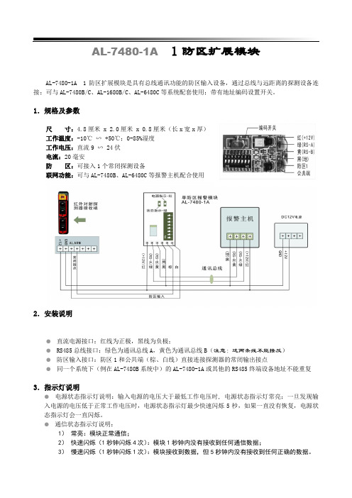
AL-7480-1A 1 防区扩展模块AL-7480-1A 1防区扩展模块是具有总线通讯功能的防区输入设备,通过总线与远距离的探测设备连接;可与AL-7480B/C 、AL-1680B/C 、AL-6480C 等系统配套使用;带有地址编码设置开关。
1.规格及参数尺 寸:4.8厘米 x 2.0厘米 x 0.8厘米(长x 宽x 厚)工作温度:-10℃ ∽ +50℃;0-85%湿度工作电压:直流9 ∽ 24伏电流:20毫安防 区:可接入1个常闭探测设备联网功能:可与AL-7480B 、AL-6480C 等报警主机配合使用2.安装说明● 直流电源接口:红线为正极,黑线为负极;● RS485总线接口:绿色为通讯总线A ,黄色为通讯总线B (注意:这两条线不能接反) ● 防区输入接口:防区1和公共端(棕、白线)直接连接探测器的常闭输出接点● 同一个系统下(例在AL-7480B 系统中)的AL-7480-1A 或其他的RS485终端设备地址不能重复3.指示灯说明● 电源状态指示灯说明:输入电源的电压大于最低工作电压时, 电源状态指示灯常亮;一旦发现输入电源的电压低于正常工作电压时,电源状态指示灯最少快速闪烁5秒,如果一直没有恢复,电源状态指示灯会一直闪烁。
● 通信状态指示灯说明:1) 常亮:模块正常通信;2) 快速闪烁(1秒钟闪烁4次):模块1秒钟内没有接收到任何通信数据;3) 慢速闪烁(1秒钟闪烁1次):模块接收到数据,但5秒钟内没有接收到任何正确的数据。
4. 地址编码开关在将AL-7480-1A接入系统使用时,必须对其进行地址编码,编码通过编码开关进行设置,地址编码采用2进制编码方式。
编码开关按“12345678”顺序排列设置二进制地址。
例如:某防区扩展模块的编码为13;对应的位二进制数为:00001101,在地址拨码开关对应的顺序为1-8(即高位为1,低位为8)1,2,3,4,7位不动, 5,6,8位拨到”ON”一边附:地址编码表注意:请按照本安装指南进行安装;在连接AL-7480-1A之前请先断开系统电源。
艾礼安ALII说明书

可最多接入15个键盘,独立操作,汉字界面。其中1个主键盘、14个从键盘通讯口1和通讯口2分别最多可接7个从键盘),通过主键盘编程可以让任意键盘跟随所有报警并显示报警信息。
设备、防区名称汉字任意更改,电脑配置,每个设备、防区最多支持7个汉字
挂在通讯总线上的设备都可以带有1-64个输出,其中报警模块最多带有1个输出,联动输出设备最多可带64个输出。每个防区可以联动最多3个输出,联动包括:防区报警联动、防区布撤防联动、防区异常联动。可以达到电子地图、DVR报警输入、就地报警等功能
有3个密码权限,包括管理、编程、操作
通过局域网(TCP/IP)可实现与中心计算机连接,最多支持两个中心(必须外加IP800接口模块)
可通过电话线与报警中心通过Contact ID协议连接,并可电话通知用户
通过键盘密码、遥控器、中心计算机、电话进行撤/布防
通过管理员密码撤布防,同时对所有键盘进行撤布防;对主键盘(键盘地址位0,挂接在键盘总线上)的撤布防,通过编程跟随设置,可以让其中一个从键盘或所有从键盘同时布撤防。
报警状态ﻩﻩﻩ850mA
输出电源ﻩﻩDC12V800mA
报警输出口ﻩ常开信号
外观尺寸ﻩﻩﻩ264 x217 x46mm
键盘端口总线总长度不得大于1200m
通讯端口总线总长度每个接口不得大于1200m,两个接口最多可达2400m
ﻬ第一章. 系统配置及连线说明
- 1、下载文档前请自行甄别文档内容的完整性,平台不提供额外的编辑、内容补充、找答案等附加服务。
- 2、"仅部分预览"的文档,不可在线预览部分如存在完整性等问题,可反馈申请退款(可完整预览的文档不适用该条件!)。
- 3、如文档侵犯您的权益,请联系客服反馈,我们会尽快为您处理(人工客服工作时间:9:00-18:30)。
AL-7480B升级版用户指南
键盘布防
键盘布防有两种方法,其操作如下:
方法一:遥控器按“B”键
方法二:键盘操作【密码】+【进入】键
在退出延时期间,蜂鸣器将鸣音。
同时LCD显示“正在布防…”,所设置的退出延时时间结束后,键盘的布防状态指示灯将持续闪烁,同时LCD显示“布防状态”。
注意:如果某一分区同时被两个或两个以上键盘拥有,只有这几个键盘全都处在布防状态下,公共分区才会布防,否则该分区撤防。
键盘撤防
键盘撤防有两种方法,其操作如下:
方法一:遥控器按“C”键
方法二:键盘操作【密码】+【退出】键
布防状态指示灯将熄灭,同时LCD显示“撤防状态”字样表示此键盘所管辖的所有分区已进入撤防状态。
键盘报警后,撤防会停止当前报警。
单个设备操作(包括单个分区、防区撤布防、联动设备打开和关闭):
键盘操作:【密码】+【旁路】
第一步:【密码】+【旁路】键→此时键盘显示“输入设备号:”;
第二步:输入设备号,共5位数字:前面三位代表设备编号,后面两位代表该设备上的防区号或输出点数(具体请参考下面说明)→输入完成后,键盘显示设备名称;
第三步:按【进入】键,对设备进行布防或合上;按【退出】键,对设备进行撤防或断开;如果被操作的设备为报警主机,提示输入该主机的密码,然后再按【进入】或【退出】键进行布撤防
操作。
重复第二、第三步,对相关设备进行操作。
在这过程中:如果没有输入5位设备号,直接按【退出】键,退出当前操作;在设备号输入错误时,可以按【↓】或【↑】来取消输入的设备号。
注意:
5位设备编号说明,前面三位代表设备编号,000-127,表示128个分区设备(其中127号设备为ES6100本身的2个防区);后面两位代表该设备上的防区编号或输出点数,如果后面两位输入为00,表示对该设备所有防区或输出进行同时操作。
如果该设备为报警模块或报警主机,此时是对该设备或某个防区进行撤布防操作;如果该设备为继电器模块,是合上或断开该设备的所有或某一继电器;如果该设备为指示灯模块,是点亮或熄灭该设备的所有或某一路指示灯。
举例:
1)假设000号设备为报警模块,输入00000,表示对000号模块进行单分区布撤防;
输入00001,表示对000号模块的第一防区进行单防区布撤防。
2)假设060号设备为指示灯模块,输入06000,表示点亮或熄灭60号设备上的所有指示灯;
输入06028,表示点亮或熄灭60号设备上的28号指示灯。
停止当前报警:
【密码】+【↓】(操作密码权限)
主机和键盘正在报警时,输入【密码】+【↓】键,键盘和主机的警号停止报警,同时键盘的蜂鸣器停止鸣响。
停止当前报警显示:
【密码】+【↑】(操作密码权限)
主机报警后,键盘上会显示报警过的信息。
此时,输入【密码】+【↑】键,键盘上的所有报警显示信息清除,同时所有的报警联动指示灯熄灭。
键盘显示说明
在没有报警的情况下,键盘会显示异常的防区;一旦有报警,键盘会显示报警信息,直到下一次布防后,或通过输入【密码】+【↓】键,清除显示信息。
如果在同一时间内有多个信息显示,键盘会轮流显示。
功能编程操作:
【密码】+【功能】
输入要操作的键盘数(如果没有输入键盘数,默认为选择主键盘),按【进入】键,根据显示的菜单,按【进入】键进入相关功能,按【↓】和【↑】键选择相邻项功能,根据提示输入数字或其它键,按【退出】键退回上一级菜单。
注意:
1) 对主键盘(键盘地址编码为“0”,挂接在键盘总线上)进行布防、撤防操作时,同时对其它键盘
进行布防、撤防操作;
2) 对从键盘的操作,如布防、撤防只对当前键盘所分配的分区有效,不影响其他键盘所分配的分区
设备;
3) 在任意键盘上通过管理员密码进行布防、撤防操作时,同时对其它键盘进行布防、撤防操作。