7-1393480-6中文资料
上海市建筑和装饰工程概算定额(2010)人工、材料、机械价格清单

材料 材料 材料 材料 材料 材料 材料 材料 材料 材料 材料 材料 材料 材料 材料 材料 材料 材料 材料 材料 材料 材料 材料 材料 材料 材料 材料 材料 材料 材料 材料 材料 材料 材料 材料 材料 材料 材料 材料 材料 材料 材料 材料 材料 材料 材料 材料
波形瓦 150×150×8 钢化玻璃普型 厚6 磨砂普通平板玻璃 彩釉地砖 镭射玻璃地砖 耐酸瓷板 180×110×30 铸石板 180×110×30 耐酸瓷板 150×150×30 花岗石 600×400×120 耐酸瓷砖 230×113×113 普通橡胶板 厚3 橡胶密封条 PVC-U雨水管管卡 75×50 PVC-U雨水斗方管 75×50 PVC-U方接圆 50 PVC-U雨水管 60×40 PVC-U 梯型檐钩 PVC-U有嘴檐沟接头 PVC-U梯型横水流闷头 PVC-U梯型檐钩接头 PVC横水流铁质托钩 聚氯乙烯薄膜 塑料隔断 塑料排水板 橡胶止水带 红泥PVC波形板 720×1800×1 红泥PVC脊瓦 250×720 橡胶条 橡皮条 耐热胶垫 2×38 橡胶条(大) 橡胶条(小) 橡皮垫片 250宽 橡皮垫片 25宽 密封胶条 高压胶管 普通橡胶管 橡皮球胆 皮管摊销 1" 磨艺术线条 密封膏 592ml 大力胶 有机玻璃板 聚氯乙烯薄膜粘带 厚0.14 PVC软管 Ф 20 黑胶布 铝收口条
10.17
3035.40 2580.09 2584.17 2584.17 50.00 5500.00
45 46 47 48 49 50 51 52 53 54 55 56 57 58 59 60 61 62 63 64 65 66 67 68 69 70 71 72 73 74 75 76 77 78 79 80 81 82 83 84 85 86 87 88 89 90 91
苯基硅橡胶在航空航天领域的应用研究

苯基硅橡胶在航空航天领域的应用研究刘 琳,金 磊(同济大学材料科学与工程学院,上海201804)摘要:对比研究牌号为SE6660,SE6635和SE5563U的甲基乙烯基苯基硅橡胶(简称苯基硅橡胶)及其硫化剂DCBP 和DBPH对航空航天领域的适用性。
结果表明:SE5563U苯基硅橡胶的综合性能较好;采用硫化剂DBPH的SE5563U苯基硅橡胶交联密度大,抗撕裂性能好,压缩永久变形小,脆化温度为-110 ℃,非常适用于航空航天器材门窗系统密封材料。
关键词:甲基乙烯基苯基硅橡胶;压缩永久变形;脆化温度;航空航天中图分类号:TQ333.93;TQ336.4+2 文章编号:1000-890X(2020)02-0119-04文献标志码:A DOI:10.12136/j.issn.1000-890X.2020.02.0119甲基乙烯基苯基硅橡胶(简称苯基硅橡胶)是在乙烯基硅橡胶的分子链中引入二苯基硅氧烷链节(或甲基苯基硅氧烷链节)而制成的,是通过引入大体积的苯基破坏二甲基硅氧烷结构的规整性来降低聚合物的结晶温度和玻璃化温度[1-2]。
苯基含量(苯基与硅原子物质的量比)为5%~10%的苯基硅橡胶通称低苯基硅橡胶,其脆化温度低(最低-115 ℃),具有优异的耐低温性能,在-100 ℃下仍具有弹性[3-4]。
随着苯基含量的增大,分子链的刚性增大,其结晶温度上升。
苯基含量为15%~25%的苯基硅橡胶通称中苯基硅橡胶,具有耐燃烧特点[5]。
苯基含量在30%以上的苯基硅橡胶通称高苯基硅橡胶,具有优良的耐辐射性能。
高苯基硅橡胶应用在要求耐低温、耐烧蚀、耐高能辐射、隔热等的场合[6]。
苯基硅橡胶由于具有独特的耐高低温、耐氧、耐光和耐气候老化等性能,是航空航天等国防尖端工业不可缺少的密封材料胶种[7-8]。
本工作选择两种过氧化物硫化剂[硫化剂DCBP(2,4-二氯过氧化苯甲酰)和硫化剂DBPH (2,5-二甲基-2,5-二叔丁基过氧化己烷)进行对比研究,旨在确定合适的硫化剂,以制得性能优异的苯基硅橡胶,为苯基硅橡胶在航空航天领域中的应用提供参考。
MT78740 02-2017 数据手册说明书

MTMT00A08-1415034-19-1415043-17-1393163-37-1415043-1 8-1393163-3MTMT00A0..MT7874002-2017, Rev. © 2015 Tyco Electronics Corporation,a TE Connectivity Ltd. company Datasheets and product specification according to IEC 61810-1 and to be used only together with the ‘Definitions’ section.Datasheets and product data is subject to the terms of the disclaimer and all chapters of the ‘Definitions’ section, available at /definitionsDatasheets, product data, ‘Definitions’ sec-tion, application notes and all specifications are subject to change.1SCHRACKn Snap-on mounting on DIN-rail n Screw mountingn Pozidrive screws with rising clamp terminals n Logical layout of input-/output connections n White marking areaMT DIN-rail sockets with screw-type terminalsMT 78 750 MT3 DIN-rail socket with screw-type terminals, 11-pin MT 78 755 MT2 DIN-rail socket with screw-type terminals, 8-pinMT78 760 MT3 DIN-rail socket with screw-type terminals, 11-pinMT 78 740 MT3 DIN-rail socket with screw-type terminals, 11-pin MT 78 745 MT2 DIN-rail socket with screw-type terminals, 8-pinGeneral Purpose Relays AccessoriesAccessories Multimode Relay MTZF0235-BF0103-BS0414-AB S0414-ACF0103-BS0311-BB S0414-AAF0200-BS0366-ASocket system MT 78 740 and MT 78 745n 8/11 pin socket for MT2 / MT3n Double A2 screw for simple further connection of coil supplyZ Zb02-2017, Rev. 0217© 2015 Tyco Electronics Corporation, a TE Connectivity Ltd. company Datasheets and product specificationaccording to IEC 61810-1 and to be usedonly together with the ‘Definitions’ section.Datasheets and product data is subject to theterms of the disclaimer and all chapters ofthe ‘Definitions’ section, available at/definitionsDatasheets, product data, ‘Definitions’ sec-tion, application notes and all specificationsare subject to change.2SCHRACKType Part NumberMT 28 800Metal retaining clip MT 8-1393163-0LED and Protection modules for MT 78 740, MT 78 745Type Part NumberMTM T0 0A0Protection diode 1N4007 (A1+, A2-) 7-1393163-6MTM U0 730RC-network 110...230 VAC 7-1393163-8MTM L0 024red LED 24 VAC / VDC 7-1393163-4Function modules for MT 78 740, MT 78 745Type Part NumberMTM Z0 W00 Delay ON 7-1393163-9MTM F0 W00Multifunction 7-1393163-3Technical data - Function modulesNominal voltage 24...240 VDC / VACMains frequency 48...63 HzPrecision of time setting + 0.5 %Readiness for repetition ≤ 0.5 % or 5 msInfluence of temperature ≤ 0.1 %/°CTime range switchable 0.05s...240h in 8 rangesMaterial compliance: EU RoHS/ELV, China RoHS, REACH, Halogen contentrefer to the Product Compliance Support Center at/customersupport/rohssupportcenterAmbient temperature range -25…+55˚CGeneral Purpose RelaysAccessoriesAccessories Multimode Relay MT (Continued)ApprovalsVDE Cert. No. 40009096, cULus E135149Technical data MT78 750/755/760/740/745Rated voltage/Max. switching voltage AC 240/400 VACRated current 10 ADielectric strengthcoil-contact circuit 2500 V rmsopen contact circuit 1500 V rmsadjacent contact circuit 2500 V rmsClearance / creepage coil-contact circuit ≥ 2.8/4 mmMaterial group of insulation parts IIIaInsulation to IEC 60664-1Type of insulation coil-contact circuit basicopen contact circuit functionaladjacent contact circuits basicRated insulation voltage 250 VPollution degree 2Rated voltage system 230/400 VOvervoltage category IIIMaterial compliance: EU RoHS/ELV, China RoHS, REACH, Halogen contentrefer to the Product Compliance Support Center at/customersupport/rohssupportcenterAmbient temperature range -20…+80˚CTerminals screwTerminal screw torque acc. IEC 61984 0.5 Nmmax. 0.7 NmWire strip length 9 mmWire cross sectionsingle wire 2 x 2.5 mm2fine wire 2 x 2.5 mm2with bootlace crimp (DIN 46228/1) 2 x 1.5 mm2Insertion cycles A (10)Max. Insertion Force total 100 NMounting distance ≥ 0 mm, dense packingWeightMT 78 750/760 54 gMT 78 755 47 gMT 78 740 62 gMT 78 745 56 gPackaging unit 25 pcsDIN-rail sockets with screw-type terminalsType Part NumberMT 78 750DIN-rail socket with screw-type 1415035-1terminals, 11-pinMT 78 755DIN-rail socket with screw-type 3-1415035-1terminals, 8-pinMT 78 760DIN-rail socket with screw-type 8-1415034-1terminals, 11-pinMT 78 740DIN-rail socket with screw-type 8-1393163-3terminals, 11-pinMT 78 745DIN-rail socket with screw-type8-1393163-4F0201-BF0203-BF0204-B02-2017, Rev. 0117© 2015 Tyco Electronics Corporation, a TE Connectivity Ltd. company Datasheets and product specificationaccording to IEC 61810-1 and to be usedonly together with the ‘Definitions’ section.Datasheets and product data is subject to theterms of the disclaimer and all chapters ofthe ‘Definitions’ section, available at/definitionsDatasheets, product data, ‘Definitions’ sec-tion, application notes and all specificationsare subject to change.3SCHRACKFunction modules for MT 78 740, MT 78 745FunctionDelay ONDelay OFFsingle shot leading edgesingle shot trailing edgeDelay ONtriggerd by signal contactsingle shotflasher starting with pauseflasher starting with pulseAccessories Multimode Relay MT(Continued)Technical data MT78 602/603/612/613Rated voltage/Max. switching voltage AC 240/400 VACRated current 10 ADielectric strengthcoil-contact circuit 2500 V rmsopen contact circuit 1500 V rmsadjacent contact circuits 2500 V rmsClearance / creepage coil-contact circuit ≥ 2.8/4 mmMaterial group of insulation parts IIIaInsulation to IEC 60664-1Type of insulation coil-contact circuit basicopen contact circuit functionaladjacent contact circuits basicRated insulation voltage 250 VPollution degree 2Rated voltage system 230/400 VOvervoltage category IIIMaterial compliance: EU RoHS/ELV, China RoHS, REACH, Halogen contentrefer to the Product Compliance Support Center at/customersupport/rohssupportcenterAmbient temperature range -40…+70˚CTerminals pcb, solder terminalsInsertion cycles A (10)Max. Insertion Force total 100 NMounting distance ≥ 0 mm, dense packingResistance to soldering heat 270°C/10sWeight 7 gPackaging unit 25 pcsSockets with solder and PCB terminalsType Part NumberMT 78 612Socket 8-pin with solder terminals 7-1415043-1MT 78 613Socket 11-pin with solder terminals 8-1415043-1MT 78 602Socket 8-pin with PCB terminals 9-1415043-1MT 78 603Socket 11-pin with PCB terminals 1415044-1MT 78 613Socket 11-pin with solder terminalsMT 78 603Socket 11-pin with PCB terminalsF0107-AS0309-AAF0104-AS0309-ABF0105-AS0309-ACF0106-AS0309-ADGeneral Purpose RelaysAccessoriesMTMT00A08-1415034-19-1415043-17-1393163-37-1415043-1 8-1393163-3MTMT00A0..MT78740。
1884678资料

Extract from the onlinecatalogVC-MP-S1Order No.: 1884720The illustration shows versions, powder-coated and EMC-coated box mounting basehttp://eshop.phoenixcontact.de/phoenix/treeViewClick.do?UID=1884720Box mounting base, made of metal, powder-coated type 1, number of modules 2, cable screw connection Pg16http://Please note that the data givenhere has been taken from theonline catalog. For comprehensiveinformation and data, please referto the user documentation. TheGeneral Terms and Conditions ofUse apply to Internet downloads. Technical dataGeneral characteristicsNote When using fiber optics, the bending radii of the cablemanufacturers must be observed.Design VC 4Degree of protection IP65/IP66/IP67Type of the screw connection Pg21Pg screw connection NoneHeight61 mmNumber of module slots5Housing material Zinc die-castHousing surface material Nickel-platedSeal material EPDM, conductiveAmbient temperature (operation)-40 °C ... 125 °CAccessoriesItem Designation DescriptionGeneral1885619VC-M-KV-PG21 1X6/2X9Multiple screw connection Pg21, made of metal, consisting ofrubber seal with several holes and a pressure screw, for cablescrew connection support VC-M-KV-PG21...1885635VC-M-KV-PG21 2X6/2X8Multiple screw connection Pg21, made of metal, consisting ofrubber seal with several holes and a pressure screw, for cablescrew connection support VC-M-KV-PG21...1885648VC-M-KV-PG21 2X7,2/1X10,5Multiple screw connection Pg21, made of metal, consisting ofrubber seal with several holes and a pressure screw, for cablescrew connection support VC-M-KV-PG21...1885651VC-M-KV-PG21 3X7Multiple screw connection Pg21, made of metal, consisting ofrubber seal with several holes and a pressure screw, for cablescrew connection support VC-M-KV-PG21...1885664VC-M-KV-PG21 3X9Multiple screw connection Pg21, made of metal, consisting ofrubber seal with several holes and a pressure screw, for cablescrew connection support VC-M-KV-PG21...1885677VC-M-KV-PG21 4X6,5Multiple screw connection Pg21, made of metal, consisting ofrubber seal with several holes and a pressure screw, for cablescrew connection support VC-M-KV-PG21...1885680VC-M-KV-PG21 4X8Multiple screw connection Pg21, made of metal, consisting ofrubber seal with several holes and a pressure screw, for cablescrew connection support VC-M-KV-PG21...1853997VC-M-KV-PG21( 7-10,5)Half screw connection Pg21, made of metal, consisting ofrubber seal with one hole and one pressure screw, for type 2 - 4housings, cable [mm] 7 - 10.51854006VC-M-KV-PG21( 9-13)Half screw connection Pg21, made of metal, consisting ofrubber seal with one hole and one pressure screw, for type 2 - 4housings, cable [mm] 9 - 131854035VC-M-KV-PG21(11,5-15,5)Half screw connection Pg21, made of metal, consisting ofrubber seal with one hole and one pressure screw, for type 2 - 4housings, cable [mm] 11.5 - 13.51854048VC-M-KV-PG21(14-18)Half screw connection Pg21, made of metal, consisting ofrubber seal with one hole and one pressure screw, for type 2 - 4housings, cable [mm] 14 - 181854051VC-M-KV-PG21(17-20,5)Half screw connection Pg21, made of metal, consisting ofrubber seal with one hole and one pressure screw, for type 2 - 4housings, cable [mm] 17 - 20.51885305VC-M-KV-PG21(20X 7)Single screw connection PG21, made of metal, consisting ofrubber seal with a long hole and pressure screw, for type 2-4housings, cable [mm] 20 x 7 mm (for flat-ribbon cable) 1854970VC-M-KV-PG21- 1X8,5/1X12Half screw connection Pg21, made of metal, consisting of rubberseal with several holes and one pressure screw, for type 2 - 4housings:Marking1852875VC-BZS WH Marker labels, unprinted, 5-section, for individual labeling with M-PEN or CMS system, whiteDrawings Dimensioned drawingAddressPHOENIX CONTACT GmbH & Co. KGFlachsmarktstr. 832825 Blomberg,GermanyPhone +49 5235 3 00Fax +49 5235 3 41200http://www.phoenixcontact.de© 2008 Phoenix ContactTechnical modifications reserved;。
1773789资料

Page 1 / 3 Mar 1, 2008
元器件交易网
HC-HV 6-AMQ Order No.: 1773789
http://eshop.phoenixcontact.de/phoenix/treeViewClick.do?UID=1773789
Length Housing type Locking type Degree of protection Ambient temperature (operation) Housing material Housing surface material Seal material Locking latch material Material grip body interlock Length of the assembly cutout Width of the assembly cutout Certificates / Approvals
Technical data General data Note Design Height Width For contact inserts HV-HV6 HV6 27 mm 43 mm
ቤተ መጻሕፍቲ ባይዱ
PHOENIX CONTACT GmbH & Co. KG http://www.phoenixcontact.de
114 mm Panel mounting base, straight With double locking latch IP65 -40 °C ... 125 °C Aluminum, die-cast Powder-coated, gray NBR High-grade steel PA-GF 86 mm 35 mm
HC-HV 6-AMQ Order No.: 1773789
1777086中文资料

Extract from the onlinecatalogMSTBV 2,5/ 3-GF-5,08Order No.: 1777086The figure shows a 10-position version of the producthttp://eshop.phoenixcontact.de/phoenix/treeViewClick.do?UID=1777086Header, nominal current: 12 A, rated voltage: 250 V, pitch: 5.08 mm, no. of positions: 3, mounting: Solderinghttp://Please note that the data givenhere has been taken from theonline catalog. For comprehensiveinformation and data, please referto the user documentation. TheGeneral Terms and Conditions ofUse apply to Internet downloads. Technical dataDimensions / positionsPitch 5.08 mmDimension a10.16 mmNumber of positions3Pin dimensions 1 x 1 mmHole diameter 1.4 mmTechnical dataInsulating material group IIIaRated surge voltage (III/3) 4 kVRated surge voltage (III/2) 4 kVRated surge voltage (II/2) 4 kVRated voltage (III/2)320 VRated voltage (II/2)400 VConnection in acc. with standard EN-VDENominal current I N12 ANominal voltage U N250 VMaximum load current12 AInsulating material PBTInflammability class acc. to UL 94V0Certificates / ApprovalsCSANominal voltage U N300 VNominal current I N10 ACULNominal voltage U N300 VNominal current I N10 AULNominal voltage U N300 VNominal current I N10 ACertification CB, CSA, CUL, GL, GOST, RS, UL, VDE-PZI AccessoriesItem Designation DescriptionAssembly1755477MSTB-BL Keying cap, for forming sections, plugs onto header pin, greeninsulating materialMarking1051993B-STIFT Marker pen, for manual labeling of unprinted Zack strips, smear-proof and waterproof, line thickness 0.5 mm0804293SK 5,08/3,8:FORTL.ZAHLEN Marker card, printed horizontally, self-adhesive, 12 identicaldecades marked 1-10, 11-20 etc. up to 91-(99)100, sufficient for120 terminal blocks0805085SK 5,08/3,8:SO Marker card, special printing, self-adhesive, labeled acc. tocustomer requirements, 12 identical marker strips per card, max.25-position labeling per strip, color: white0805412SK 5,08/3,8:UNBEDRUCKT Marker cards, unprinted, with pitch divisions, self-adhesive, 10-section marker strips, 12 strips per card, can be labeled with theM-PENPlug/Adapter1734401CR-MSTB Coding section, inserted into the recess in the header or theinverted plug, red insulating materialAdditional productsItem Designation DescriptionGeneral1873210FKC 2,5/ 3-STF-5,08Plug with screw flange, nominal current: 12 A, rated voltage: 250V, pitch: 5.08 mm, no. of positions: 3, type of connection: Spring-cage connection1902314FKCT 2,5/ 3-STF-5,08Plug component, nominal current: 12 A, rated voltage: 250 V,pitch: 5.08 mm, no. of positions: 3, type of connection: Spring-cage connection1874112FKCVR 2,5/ 3-STF-5,08Plug component, nominal current: 12 A, rated voltage: 250 V,pitch: 5.08 mm, no. of positions: 3, type of connection: Spring-cage connection1873812FKCVW 2,5/ 3-STF-5,08Plug component, nominal current: 12 A, rated voltage: 250 V,pitch: 5.08 mm, no. of positions: 3, type of connection: Spring-cage connection1777811FRONT-MSTB 2,5/ 3-STF-5,08Plug with screw flange, nominal current: 12 A, rated voltage: 250V, pitch: 5,08 mm, no. of positions: 3, type of connection: Screwconnection1777992MSTB 2,5/ 3-STF-5,08Plug component, nominal current: 12 A, rated voltage: 250 V,pitch: 5.08 mm, no. of positions: 3, type of connection: Screwconnection1809747MSTBC 2,5/ 3-STZF-5,08Plug component, nominal current: 12 A, rated voltage: 320 V,pitch: 5.08 mm, no. of positions: 3, type of connection: Crimpconnection1805314MSTBT 2,5/ 3-STF-5,08Plug with T-shape and screw flange, nominal current: 12 A,rated voltage: 250 V, pitch: 5.08 mm, no. of positions: 3, type ofconnection: Screw connection1835106MVSTBR 2,5/ 3-STF-5,08Plug with screw flange, nominal current: 12 A, rated voltage: 250V, pitch: 5,08 mm, no. of positions: 3, type of connection: Screwconnection1834916MVSTBW 2,5/ 3-STF-5,08Plug component, nominal current: 12 A, rated voltage: 250 V,pitch: 5.08 mm, no. of positions: 3, type of connection: Screwconnection1918104QC 0,75/ 3-STF-5,08Plug components, 5.08 mm pitch, color: green, no. of positions 3,dimension a 10.16 mm1883365QC 1/ 3-STF-5,08Plug, nominal current: 10 A, rated voltage: 500 V, pitch: 5.08mm, number of positions: 3, connection method: Insulationdisplacement connection QUICKON1853117TMSTBP 2,5/ 3-STF-5,08Plug component, nominal current: 12 A, rated voltage: 250 V,pitch: 5.08 mm, no. of positions: 3, type of connection: Screwconnection1873029ZFKK 1,5-ICV-5,08Modular terminal blocks with plug entry, cross section: 0.2 - 1.5mm², width: 5.1 mm, color: grayDrawingsDrilling diagramDimensioned drawingAddressPHOENIX CONTACT GmbH & Co. KGFlachsmarktstr. 832825 Blomberg,GermanyPhone +49 5235 3 00Fax +49 5235 3 41200http://www.phoenixcontact.de© 2008 Phoenix ContactTechnical modifications reserved;。
GL823K Datasheet
GL823KUSB 2.0 SD Card Reader ControllerDatasheetRevision HistoryTable of ContentsCHAPTER 1GENERAL DESCRIPTION (6)CHAPTER 2FEATURES (7)CHAPTER 3PIN ASSIGMENT (8)3.1SSOP16 Pinout (8)3.2Pin Description (9)CHAPTER 4BLOCK DIAGRAM (10)4.1OCCS USB PHY (10)4.2SIE (10)4.3EPFIFO (10)4.4MCU (10)4.5MHE (11)4.6Regulator (11)4.7PMOS (11)CHAPTER 5ELECTRICAL CHARACTERISTICS (12)5.1Temperature Conditions (12)5.2Operating Conditions (12)5.3DC Characteristics (12)5.4Memory Card Clock Frequency (12)5.5Maximum Ratings (13)CHAPTER 6PACKAGE DIMENSION (14)CHAPTER 7ORDERING INFORMATION (15)List of FiguresFigure 3.1 – SSOP 16 Pinout Diagram (8)Figure 6.1 – SSOP 16 Pin Package (150 mil) (14)List of TablesTable 3.1 – Pin Description (9)Table 4.1 – Functional Block Diagram (10)Table 5.1 – Temperature Conditions (12)Table 5.2 – Operating Conditions (12)Table 5.3 – DC Characteristics (12)Table 5.4 – SD/MMC Card Clock Frequency (12)Table 5.5 – Maximum Ratings (13)Table 7.1 – Ordering Information (15)CHAPTER 1GENERAL DESCRIPTIONThe GL823K is a USB 2.0 Single-LUN card reader controller which can support SD/MMC Flash Memory Cards. It supports USB 2.0 high-speed transmission to Secure Digital TM(SD), SDHC, SDXC, miniSD TM, microSD TM(T-Flash), MultiMediaCard TM (MMC), RS MultiMediaCard TM (RS MMC), MMCmicro , HS-MMC and MMCmobile. As a single chip solution for USB 2.0 flash card reader, the GL823K complies with Universal Serial Bus specification rev. 2.0, USB Storage Class Specification ver.1.0, and each flash card interface specification.The GL823K integrates a high speed 8051 microprocessor and a high efficiency hardware engine for the best data transfer performance between USB and flash card interfaces. Its pin assignment design fits to card sockets to provide easier PCB layout. Inside the chip, it integrates 5V to 3.3V regulator, 3.3V to 1.8V regulator and power MOSFETs and it enables the function of on-chip clock source (OCCS) which means no external 12MHz XTAL is needed and that effectively reduces the total BOM cost.The GL823K implements USB disconnect function; it can be used for Mobile cable/ OTG reader/ PC card reader application.CHAPTER 2FEATURES●USB specification compliance-Comply with 480Mbps Universal Serial Bus specification rev. 2.0-Comply with USB Storage Class specification rev. 1.0-Support one device address and up to four endpoints: Control (0)/Bulk Read (1)/Bulk Write (2)/Interrupt (3) ●Integrated USB building blocks-USB2.0 transceiver macro (UTM), Serial Interface Engine (SIE), Build-in power-on reset (POR) and low-voltage detector (LVD)●Embedded 8051 micro-controller-Operate @ 60 MHz clock, 12 clocks per instruction cycle-Embedded mask ROM and internal SRAM●Secure Digital TM (SD) and MultiMediaCard TM (MMC)-Supports SD specification v1.0 / v1.1 / v2.0 / SDHC (Up to 32GB)-Compatible with SDXC (Up to 2TB)-Supports MMC specification v3.x / v4.0 / v4.1 / v4.2-Supports 1 / 4 bit data bus-Compliant with Secure Digital TM v5.0●Support boost mode for SD3.0 for better performance●Support non-SD Card Detect pin, non-MS Insertion/Removal pin design to save BOM cost●Support non-SD Write Protection pin design to save BOM cost●Support LED function to indicate power and access status●On chip clock source and no need of 12MHz Crystal Clock input●On-Chip 5V to 3.3V and 3.3V to 1.8V regulators●On-Chip power MOSFET for supplying flash media card power●Support USB disconnection by memory card unplug or manual switch for Mobile cable/ OTG reader/ PCcard reader application●Available in SSOP16 package (150 mil)CHAPTER 3 PIN ASSIGMENT3.1 SSOP16 Pinout38765214D 0D 2P M O S C M D V S S D 1D 3C L KFigure 3.1 – SSOP 16 Pinout Diagram3.2Pin DescriptionTable 3.1 – Pin DescriptionNotation:Type O OutputI InputB Bi-directionalpu internal pull-up when inputpd internal pull-down when inputP Power / GroundA AnalogCHAPTER 4BLOCK DIAGRAMTable 4.1 – Functional Block Diagram4.1OCCS USB PHYThe USB 2.0 Transceiver Macrocell is the analog circuitry that handles the low level USB protocol and signaling, and shifts the clock domain of the data from the USB 2.0 rate to one that is compatible with the general logic. On chip clock source and no need of 12MHz Crystal Clock input.4.2SIEThe Serial Interface Engine, which contains the USB PID and address recognition logic, and other sequencing and state machine logic to handle USB packets and transactions.4.3EPFIFOEndpoint FIFO includes Control FIFO (FIFO0) and Bulk In/Out FIFO●EP0 FIFO FIFO of control endpoint 0. It is 64-byte FIFO and used for endpoint 0 data transfer.●Interrupt FIFO 64-byte depth FIFO of endpoint 3 for status interrupt●Bulk FIFO It can be in the TX mode or RX mode:1. It contains ping-pong FIFO (512 bytes each bank) for transmit/receive data continuously.2. It can be directly accessed by micro-controller4.4MCU8051 micro-controller inside.●8051 Core Compliant with Intel 8051 high speed micro-controller●ROM FW code on ROM●SRAM Internal RAM area for MCU access4.5MHE●MIF Media Interface: SD/MMC●MCFIFO It can access by MCU for memory card short data packet.4.6Regulator●5V to 3.3V Band Gap Regulator for stable voltage supply for USB PHY, PMOS●3.3V to 1.8V For core logic and internal memory.4.7PMOSOn-Chip power MOSFETs for memory card powerCHAPTER 5ELECTRICAL CHARACTERISTICS 5.1Temperature ConditionsTable 5.1 – Temperature Conditions5.2Operating ConditionsTable 5.2 – Operating Conditions5.3DC CharacteristicsTable 5.3 – DC Characteristics5.4Memory Card Clock FrequencyTable 5.4 – SD/MMC Card Clock Frequency5.5Maximum RatingsTable 5.5 – Maximum RatingsCHAPTER 6PACKAGE DIMENSIONInternalNo.Lot CodeDateGL823KAAAAAAAAAAYWWXXXXVersionNo.Figure 6.1 – SSOP 16 Pin Package (150 mil)CHAPTER 7ORDERING INFORMATIONTable 7.1 – Ordering Information。
74649-1004中文资料
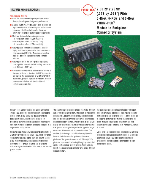
FEATURES AND SPECIFICATIONS2.00 by 2.25mm (.079 by .089") Pitch 5-Row, 6-Row and 8-Row VHDM-HSD ™Module-to-BackplaneConnector SystemFeatures and Benefitss Up to 5.0 Gbps bandwidth per signal pair enables state-of-the-art system design and performance s2.00 by 2.25mm (.079 by .089”) pitch provides real signal density of 10 differential pairs for 5-row and 6-row and 15 differential pairs for 8-row per centimeter (25 and 38 pairs respectively per inch) sMinimum distance between daughtercards:– 5-row system offers 15.00mm (.591")– 6-row system offers 18.00mm (.709")– 8-row system offers 22.00mm (.866")sGround planes between signal columns provide tightly controlled impedance for rise times down to 50 picoseconds (10-90%). This ensures very low cross talk between signals within and between columnssGround pins are in the same grid as signal pins, allowing wider channels for PCB routing and traces up to 0.25mm (.010”) wides6-row or 8-row VHDM-HSD wafers can be applied to the same stiffener as standard VHDM ® 6-row or 8-row wafers. The combination of VHDM and VHDM-HSD wafers, grouped together in the same stiffener, provides cost effective solutions to different performance parametersThe Very High Density Metric High Speed Differential (VHDM-HSD) connector system has been expanded to include 5-row, 6-row and 8-row daughtercard and backplane modules. VHDM-HSD is designed for differential-pair architecture applications that require very high interconnect density and signal integrity in a single-ended configuration.The same great modularity features and components ofVHDM are provided in the VHDM-HSD. The 5-row and 6-row systems feature 2 signal pairs per column and the8-row system features 3 signal pairs per column inincrements of 10 and 25 columns. All circuits areutilized as signal circuits without the need to use some asground circuits.The daughtercard connector consists of a metal stiffener just as with the VHDM system. The system combines the signal wafers, power modules and guidance modules into one continuous connector that can be ordered as a single specific part number. The card pitch of the VHDM-HSD 8-row system is the same as the standard VHDM 8-row system, allowing both signal wafer types for single ended and differential pair to be used together. Thismodularity and design flexibility allow engineers toincorporate both connector systems on the sameplatforms. The system is based on a 2.00mm (.079")pitch and includes vertical and right angle products thatcan be configured up to 2000 circuits. The maximumlength of a daughtercard connector on a single stiffeneris 300mm (12").The backplane connectors feature headers with open ends for continuous side-to-side stacking and headers with guide pins and polarizing keys on either end to aid in proper alignment of the mating daughtercard. The power modules occupy just a small width and hold sequentially matable pins that each manage 10.0 amps of current.Molex offers application tooling for pressing VHDM-HSD connectors into PCBs as separate modules or as complete assemblies. VHDM-HSD cable assemblies are also available for connecting backplane headers to high-performance cables.Note: VHDM and VHDM-HSD are trademarks or registered trademarks of Teradyne,Inc.元器件交易网FEATURES AND SPECIFICATIONS2.00 by 2.25mm (.079 by .089") Pitch 5-Row, 6-Row and 8-Row VHDM-HSD ™Module-to-Backplane Connector SystemPress Fit Right Angle ReceptacleApplicationsThe VHDM-HSD products are used in very high speed, short rise-time, high circuit count applications connecting daughtercards to the backplane:s Network Switches s Routerss Computer Serverss Telecommunication Equipment sInternetworking DevicesORDERING INFORMATIONDaughtercard AssemblyConfiguration 5-Row 6-Row 8-Row Signal wafers, power modules and guide modules sequentiallyassigned by application VHDM-HSD wafers74670-XXXX 74880-XXXX 74680-XXXX Combination of VHDM and VHDM-HSD wafers74686-XXXX 74886-XXXX74686-XXXXBackplane Header Signal Module Standard Loaded Pin Height 0.76µm (30µ”) Gold5-Row6-Row8-Row10-Column 25-Column 10-Column 25-Column 10-Column 25-Column Open Ended4.25mm (.167”)74695-100374695-250374979-100374979-250374649-100374649-25034.75mm (.187”)74695-100174695-250174979-100174979-250174649-100174649-25015.15mm (.203”)74695-100474695-250474979-100474979-250474649-100474649-25046.25mm (.266”)74695-100274695-250274979-100274979-250274649-100274649-2502Left Guide PinNo Polarizing Key 4.25mm (.167”)74696-100374696-2503––74650-100374650-25034.75mm (.187”)74696-100174696-2501––74650-100174650-25015.15mm (.203”)74696-100474696-2504––74650-100474650-25046.25mm (.266”)74696-100274696-2502––74650-100274650-2502Left Guide Pin“A” Polarizing Key 4.25mm (.167”)74696-101374696-2513––74650-101374650-25134.75mm (.187”)74696-101174696-2511––74650-101174650-25115.15mm (.203”)74696-101474696-2514––74650-101474650-25146.25mm (.266”)74696-101274696-2512––74650-101274650-2512Right Guide PinNo Polarizing Key 4.25mm (.167”)74697-100374697-2503––74651-100374651-25034.75mm (.187”)74697-100174697-2501––74651-100174651-25015.15mm (.203”)74697-100474697-2504––74651-100474651-25046.25mm (.266”)74697-100274697-2502––74651-100274651-2502Right Guide Pin“A” Polarizing Key 4.25mm (.167”)74697-101374697-2513––74651-101374651-25134.75mm (.187”)74697-101174697-2511––74651-101174651-25115.15mm (.203”)74697-101474697-2514––74651-101474651-25146.25mm (.266”)74697-101274697-2512––74651-101274651-2512Backplane Power and Guide Components5-Row and 6-Row 8-Row Power Module 74029-600074029-8000Keying Post 74069-001074069-0010Guide Pin74076-0001/000274076-0001/0002Americas Headquarters Lisle, Illinois 60532 U.S.A.1-800-78MOLEX amerinfo@ Far East North Headquarters Yamato, Kanagawa, Japan 81-462-65-2324feninfo@ Far East South Headquarters Jurong, Singapore 65-6-268-6868fesinfo@ European Headquarters Munich, Germany 49-89-413092-0eurinfo@ Corporate Headquarters 2222 Wellington Ct.Lisle, IL 60532 U.S.A.630-969-4550Visit our Web site at /product/backplan/hsd.htmlOrder No. USA-158 Rev. 2Printed in USA/2.5K/JI/JI/2003.03©2003, MolexNote: VHDM and VHDM-HSD are trademarks or registered trademarks of Teradyne,Inc.元器件交易网。
- 1、下载文档前请自行甄别文档内容的完整性,平台不提供额外的编辑、内容补充、找答案等附加服务。
- 2、"仅部分预览"的文档,不可在线预览部分如存在完整性等问题,可反馈申请退款(可完整预览的文档不适用该条件!)。
- 3、如文档侵犯您的权益,请联系客服反馈,我们会尽快为您处理(人工客服工作时间:9:00-18:30)。
7-1393480-6 Product Details
Home | Customer Support | Suppliers | Site Map | Privacy Policy | Browser Support
© 2008 Tyco Electronics Corporation All Rights Reserved Search
Products Documentation Resources My Account Customer Support Home > Products > By Type > D Subminiature > Product Feature Selector > Product Details
7-1393480-6 (V23529B1222C225) TE Part Number: 7-1393480-6
Active
Add to Part List Standard Board Mount Connectors
Always EU RoHS/ELV Compliant (Statement of Compliance)
Product Highlights:
?Number of Positions = 25
?Plug
?PCB Mount Angle = Right Angle
?Product Series = HD 20 Type B -
Solder Terminal
?With Mating Connector Lock
View all Features | Find Similar
Products
Check Pricing &
Availability
Search for Tooling
Product Feature
Selector
Contact Us About
This Product
Request Samples
Quick Links
Documentation & Additional Information
Product Drawings:
?D-Sub 90? solder pin connector (mounting height 3.6 mm)(PDF, English)
Catalog Pages/Data Sheets:
?COMMUNICATION PRODUCTS ADDENDUM(PDF, English)
?AMPLIMITE SUBMINATURE D TYPE CONNECTORS(PDF, English) ?AMPLIMITE Subminiature D Connectors -Right-Angle Po...(PDF, English)
Product Specifications:
?None Available
Application Specifications:
?None Available
Instruction Sheets:
?None Available
CAD Files:
?None Available
List all Documents Additional Information:
?Product Line Information
Additional Product Images: ?Schematic
?PCB Layout
Related Products:
?Tooling
Product Features (Please use the Product Drawing for all design activity)
Product Type Features:
?Number of Positions = 25
?Gender = Plug
?PCB Mount Angle = Right Angle
?Product Series = HD 20 Type B -Solder
Terminal
?Mating Connector Lock = With
?Mating Connector Lock Type = Threaded Insert,
M3
?PCB Retention Feature = Yes
?Shell Type = Full Metal
?Shell Size = 3
?Footprint (mm [in]) = 10.70 [.421]
?PCB Thickness (in [mm]) = 0.062 [1.57]
?Grounding Indents = With
?Grounding Straps = Without
?PCB Mount Style = Thru Hole
?Color Code = None
?Sealed = No
?Profile = Eurostyle -3.6 mm Installation Height
?Post Size (mm [in]) = 0.70 [.028]
?Color = Gray
?Shell Material = Steel
?Comment = Connectors are preloaded with
contacts.; With 4-40 UNC thread on request. Mechanical Attachment:
?Panel Attachment = Without
Termination Related Features:
?Grounding Clips = Without
?Termination (Solder) Post Length (mm [in]) =
3.20 [0.126]
?Solder Tail Contact Plating = Tin Body Related Features:
?PCB Retention Method = Boardlock(s)
?Insert Flammability Rating = UL 94V-0
?Insert Material = PBTP -Glass Fiber-Reinforced
Thermoplastic
?Shell Plating = Tin over Nickel
?Mounting Bracket(s) = With
Contact Related Features:
?Contact Mating Area Plating Material = Gold
(20)
?Contact Shape = Round
?Contact Material = Copper Alloy
?Mounting Bracket Insulation = Without
Industry Standards:
?RoHS/ELV Compliance = RoHS compliant, ELV
compliant
?Lead Free Solder Processes = Wave solder
capable to 240°C, Wave solder capable to 260°
C, Wave solder capable to 265°C
?RoHS/ELV Compliance History = Always was
RoHS compliant
Operation/Application:
?Application = Standard
Other:
?Brand = AMP
Provide Website Feedback | Need Help?。