MAX211ECAI+中文资料
新开普A211智能消费终端说明书

新开普A211智能消费终端说明书新开普餐饮收费机是一款基于ARM Cortex-M3平台的32位智能卡支付终端产品,采用非接触式的IC卡实现电子货币消费功能。
智能卡支付终端专为读写 CPU卡而设计,并全面兼容Mifare One卡系列卡片,具有低功耗、响应速度快,抗干扰能力强、坚固耐用等优点。
刷卡消费时,持卡人只需将存有现金的IC卡靠近消费机刷卡感应区便可完成交易。
终端机支持USB数据下载和重采集,可选择通过485、TCP、GPRS、CDMA等方式联机上传消费数据。
消费机在一卡通消费系统管理平台软件的配合下,实现消费数据的采集、查询统计、报表和帐务等管理功能。
产品新特征1.兼容原串口升级基础上;新增全速USB接口,最大速率达到12Mpbs。
2.双屏汉显。
汉字显示提示信息,人机交互更人性化。
3.选配支持无线通讯,满足分散客户需要。
4.密码按键使用触摸按键,大方美观。
5.硬件支持金融IC卡支付。
通过QPBOC认证。
6.ARM Cortex-M3 CPU,主频达到120MHz,运行速度快,稳定性高。
功能特点1. 支持13.56频率非接触式卡片,符合ISO/ICE 14443A/B标准,数据安全可靠;2. 支持符合PBOC2.0规范CPU卡片,支持金融IC卡;3. 双面3.2英寸汉字点阵液晶显示,单行支持最多8个汉字显示;4. 支持智能语音提示;5. 通讯接口可选,支持GPRS、CDMA、TCP/IP、CANBUS、RS485;6. 具有下载黑名单, 黑名单排序整理, 黑名单校验检索, 黑卡挂失等功能;7. 具有完成交易保存流水记录功能, 记录通过约定通讯方式上传上位机数据库;8. 具有简单的交易查询功能, 能设置设备工作参数,对设备进行维护和管理等;9. 具有USB接口,支持U盘升级、补采等;10. 机械按键与触摸按键相结合。
MAX2021
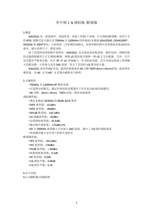
零中频I/Q调制器/解调器1.概述MAX2021是一款低噪声、高线性度、直接上变频/下变频、正交调制/解调器,适用于手持RFID、便携式读卡器以及750MHz至1200MHz的单载波/多载波GSM/EDGE、CDMA2000®、WCDMA和iDEN®基站。
与传统的二次变频结构相比,直接变频结构可显著降低发射/接收机成本,减小系统尺寸、降低功耗。
除了高线性度和低噪声优势外,MAX2021还具备很高的集成度。
器件包括:两路匹配的无源混频器用于正交调制/解调、两路LO缓冲放大器和一路LO正交分配器。
另外,芯片还内置非平衡变压器,允许RF和LO单端输入。
作为附加功能,芯片内部还集成了基带输入匹配电路,可直接与发送DAC连接,省去了昂贵的I/Q缓冲放大器。
MAX2021采用单+5V供电,提供结构紧凑的36引脚TQFN (6mm x 6mm)封装,底部带有裸焊盘。
在-40°C至+85°C范围内确保电气特性。
2.关键特性•750MHz至1200MHz RF频率范围•可选择功率模式:通过外部电阻设置器件工作在低功耗/低性能模式•36引脚、(6mm x 6mm)、TQFN封装,提供高隔离度调制器性能:•满足4载波WCDMA的65dBc ACLR要求•OIP3典型值:+21dBm•OIP2典型值:+58dBm•OP1dB典型值:+16.7dBm•LO泄漏典型值:-32dBm•边带抑制典型值:43.5dBc•输出噪声谱密度:-174dBm/Hz•DC至550MHz基带输入可直接与DAC连接,减少了I/Q缓冲器的成本•直流耦合输入允许用户控制失调电压解调器性能:•IIP3典型值:+35.2dBm•IIP2典型值:+76dBm•IP1dB典型值:> 30dBm•转换损耗典型值:9.2dB•NF典型值:9.3dB•I/Q增益平衡:0.06dB•I/Q相位平衡:0.15°3.芯片结构3.1引脚配置/功能框图引脚说明MAX2021是专为在同相(I)和正交(Q)基带的输入在650MHz到1200MHz的RF频率范围中的上变频差。
MAX213CAI-T中文资料

General DescriptionThe MAX200–MAX211/MAX213 transceivers are designed for RS-232 and V.28 communication inter-faces where ±12V supplies are not available. On-board charge pumps convert the +5V input to the ±10V need-ed for RS-232 output levels. The MAX201 and MAX209operate from +5V and +12V, and contain a +12V to -12V charge-pump voltage converter.The MAX200–MAX211/MAX213 drivers and receivers meet all EIA/TIA-232E and CCITT V.28 specifications at a data rate of 20kbps. The drivers maintain the ±5V EIA/TIA-232E output signal levels at data rates in excess of 120kbps when loaded in accordance with the EIA/TIA-232E specification.The 5µW shutdown mode of the MAX200, MAX205,MAX206, and MAX211 conserves energy in battery-powered systems. The MAX213 has an active-low shut-down and an active-high receiver enable control. Two receivers of the MAX213 are active, allowing ring indica-tor (RI) to be monitored easily using only 75µW power.The MAX211 and MAX213 are available in a 28-pin wide small-outline (SO) package and a 28-pin shrink small-outline (SSOP) package, which occupies only 40% of the area of the SO. The MAX207 is now avail-able in a 24-pin SO package and a 24-pin SSOP. The MAX203 and MAX205 use no external components,and are recommended for applications with limited circuit board space.ApplicationsComputersLaptops, Palmtops, Notebooks Battery-Powered Equipment Hand-Held Equipment Next-Generation Device Features ♦For Low-Cost Applications:MAX221E: ±15kV ESD-Protected, +5V, 1µA, Single RS-232 Transceiver with AutoShutdown™♦For Low-Voltage and Space-Constrained Applications:MAX3222E/MAX3232E/MAX3237E/MAX3241E/MAX3246E: ±15kV ESD-Protected, Down to 10nA,+3.0V to +5.5V, Up to 1Mbps, True RS-232Transceivers (MAX3246E Available in UCSP™Package)♦For Space-Constrained Applications:MAX3228E/MAX3229E: ±15kV ESD-Protected,+2.5V to +5.5V, RS-232 Transceivers in UCSP ♦For Low-Voltage or Data Cable Applications:MAX3380E/MAX3381E: +2.35V TO +5.5V, 1µA,2Tx/2Rx RS-232 Transceivers with ±15kV ESD-Protected I/O and Logic Pins ♦For Low-Power Applications:MAX3224E–MAX3227E/MAX3244E/MAX3245E:±15kV ESD-Protected, 1µA, 1Mbps, +3.0V to+5.5V, RS-232 Transceivers with AutoShutdown Plus™MAX200–MAX211/MAX213+5V , RS-232 Transceivers with 0.1µF External Capacitors ________________________________________________________________Maxim Integrated Products 119-0065; Rev 6; 10/03For pricing, delivery, and ordering information,please contact Maxim/Dallas Direct!at 1-888-629-4642, or visit Maxim’s website at .Ordering Information appears at end of data sheetAutoShutdown, AutoShutdown Plus, and UCSP are trademarks of Maxim Integrated Products, Inc.MAX200–MAX211/MAX213+5V , RS-232 Transceiverswith 0.1µF External Capacitors______________________________________________________________________________________19Ordering Information*Contact factory for dice specifications.M A X 200–M A X 211/M A X 213+5V , RS-232 Transceiverswith 0.1µF External Capacitors Maxim cannot assume responsibility for use of any circuitry other than circuitry entirely embodied in a Maxim product. No circuit patent licenses are implied. Maxim reserves the right to change the circuitry and specifications without notice at any time.20____________________Maxim Integrated Products, 120 San Gabriel Drive, Sunnyvale, CA 94086 408-737-7600©2003 Maxim Integrated ProductsPrinted USAis a registered trademark of Maxim Integrated Products.Package Information(The package drawing(s) in this data sheet may not reflect the most current specifications. For the latest package outline information,go to /packages .)。
CSC211系列说明书1
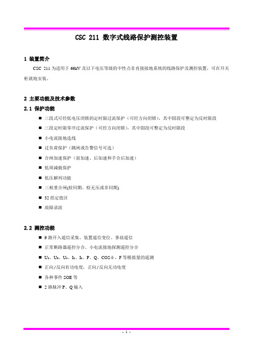
CSC 211 数字式线路保护测控装置1 装置简介CSC 211为适用于66kV及以下电压等级的中性点非直接接地系统的线路保护及测控装置,可在开关柜就地安装。
2 主要功能及技术参数2.1 保护功能⏹三段式可经低电压闭锁的定时限过流保护(可经方向闭锁),其中Ⅲ段可整定为反时限段⏹三段定时限零序过流保护(可经方向闭锁),其中Ⅲ段可整定为反时限段⏹小电流接地选线⏹过负荷保护(跳闸或告警信号可选)⏹合闸加速保护(前加速、后加速和手合后加速)⏹低周减载保护⏹低压解列功能⏹三相重合闸(检同期、检无压或非同期)⏹32组定值区⏹故障录波2.2 测控功能⏹9路开入遥信采集、装置遥信变位、事故遥信⏹正常断路器遥控分合、小电流接地探测遥控分合⏹U a、U b、U c、I a、I c、P、Q、COSф、F等模拟量的遥测⏹正向/反向有功电度,正向/反向无功电度⏹各种事件SOE等⏹2路脉冲P、Q输入2.3 技术参数3 保护元件3.1 过电流元件本装置设三段定时限过流保护,各段电流及时间定值可独立整定。
为了躲开线路避雷器的放电时间,I段可以整定适当延时时间。
方向元件及低电压元件由控制字选择投退。
注:Idzn为n段电流定值,IΦ为相电流, Tn 为n段延时定值3.2 低电压元件低电压元件在三个线电压中的任意一个低于低电压定值时动作,开放经低电压闭锁的过流元件。
利用此元件,可以保证装置在电机反充电等非故障情况下不出现误动作。
低电压元件用控制字投退。
3.3 零序过流元件在经小电阻接地系统中,接地零序电流相对较大,一般采用零序过流直接跳闸方法。
零序过流元件的实现方式基本与过流元件相似,各段电流及时间定值可独立整定。
注:I0dn为接地n段定值,T0n为接地n段延时定值3.4 方向元件相间方向元件采用90︒接线方式,按相起动,各相电流元件仅受下表中所示相应方向元件的控制。
为消除死区,方向元件带有记忆功能。
本装置Arg(U/I)= -30︒~90︒,边缘模糊角度误差<±5︒。
西门子7KM2112资料(说明书)

Sinusoidal or distorted 45 65 RMS 185.8 P
1 TRMS
65 45 AC/DC CATIII
8 6 10
IP65 IP20 II
100
5
Installation in stationary control panels in closed rooms 10
Yes Yes Yes Yes Yes Yes
s s
kbit/s kbit/s
V V V
mA mA
LCD, graphical, monochrome 4 white ger, en, fr, spa, ita, por, tur, chi
128 96
0.33 1 Yes
MODBUS TCP SEAbus TCP / MODBUS TCP (switchable)
10 000 10 000
Acc. to IEC62053-22 and IEC62053-23
Class 2 according to IEC61557-12 and/or IEC6205323 +/- 0,5 % +/- 0,5 % +/- 0,3 % +/- 0,2 % Cl. 0.5 acc. to... IEC62053-22
Measuring category / for supply voltage
Apparent power consumption
● with expansion module / maximum
V·A
● without expansion module / typical
V·A
Relative symmetrical tolerance / of the supply voltage %
AXIS 210A和AXIS 211A网络摄像头数据手册说明书

DATASHEETAXIS 210A and AXIS 211A deliver superior image quality using progressive scan, in up to 30 frames per second in 640x480 VGA resolution.Simultaneous MPEG-4 and Motion JPEG video streams can be provided, allowing for optimization in image quality and bandwidth.AXIS 210A and AXIS 211A support two-way audio, enabling remote users to not only view, but also listen in on an area and communicate orders or requests to visitors, customers or intruders.AXIS 210A and AXIS 211A Network Cameras offer a cost-effective, IP-based solution for professional security surveillance and remote monitoring, which make them an ideal choice for securing offices, shops and other indoor and outdoor facilities.AXIS 210A/211A Network CamerasSuperior video quality for professional indoor and outdoor applications.> Superior image quality > Simultaneous MPEG-4 and Motion JPEG > Two-way audio > Video motion detection > Power over EthernetAXIS 210A and AXIS 211A support video motion detection and advanced event management, including pre/post alarm image buffering. Both cameras support Power over Ethernet, allowing power to be delivered via the network, which eliminates the need for power cables and reduces installationcosts.©2008 Axis Communications AB. AXIS COMMUNICATIONS, AXIS, ETRAX, ARTPEC and VAPIX are registered trademarks or trademark applications of Axis AB in various jurisdictions. All other company names and products are trademarks or registered trademarks of their respective companies. We reserve the right to introduce modifications without notice.3 3 8 1 5 / E N / R 1 / 0 8 1 1More information is available at 5 mm (0.2”) (x3)32 mm (1.3”)。
马拉松MX系列发电机英文说明书

MAGNAMAXGENERATOR INSTALLATION OPERATION, AND MAINTENANCEMANUALTABLE OF CONTENTSTABLE OF CONTENTS (2)SAFETY (6)GENERAL INFORMATION (7)MECHANICAL DESIGN (7)General (7)Conduit Box (7)MagnaMAX Unirotor TM Construction (7)Adapters and Drive Discs (7)ELECTRICAL DESIGN (8)Temperature Rise (8)Standby Generator Ratings (8)Premium Insulation System (8)Power Factor (8)MagnaMAX Voltage Regulator (8)HOW TO READ A MODEL NUMBER (9)INSTALLATION (10)RECEIVING YOUR MAGNAMAX GENERATOR (10)UNPACKING AND HANDLING (10)STORAGE (10)PREPARATION FOR USE (10)GENERATOR MOUNTING - SINGLE BEARING (10)GENERATOR MOUNTING-TWO BEARING (11)BELT DRIVE (11)ENVIRONMENTAL CONCERNS (11)ELECTRICAL CONNECTIONS (12)GENERATOR LEAD CONNECTIONS (12)12 LEAD HIGH WYE CONNECTION (13)12 LEAD LOW WYE CONNECTION (13)12 LEAD HIGH DELTA CONNECTION (14)12 LEAD LOW DELTA CONNECTION (14)10 LEAD HIGH WYE CONNECTION (15)10 LEAD LOW WYE CONNECTION (15)6 LEAD WYE CONNECTION (16)6 LEAD DELTA CONNECTION (16)3 LEAD DELTA CONNECTION (17)4 LEAD WYE CONNECTION (17)DOUBLE DELTA -- SINGLE PHASE CONNECTION (18)LOW ZIG ZAG -- SINGLE PHASE CONNECTION (18)HIGH ZIG ZAG -- SINGLE PHASE CONNECTION (18)PARALLELING OPERATIONS (19)PRIME MOVER (19)VOLTAGE REGULATOR (19)SWITCHGEAR (19)PARALLELING BASICS (19)REACTIVE LOAD CONTROL (20)PARALLELING CIRCUITRY (20)THYRISTOR OR SCR LOADING (21)OPERATION (21)PRE-START INSPECTION (21)STARTING-UP THE GENERATOR (22)FIELD FLASHING (22)VOLTAGE ADJUSTMENTS (22)OTHER ADJUSTMENTS (23)MAINTENANCE (23)GENERAL INFORMATION (23)AIR INTAKE AND EXHAUST (23)ELECTRICAL CONNECTIONS, WINDINGS (24)LUBRICATION (24)DRYING ELECTRICAL INSULATION (26)Space Heaters (26)Oven (26)Forced Air (26)“Short Circuit” Method (26)CLEANING METHODS (27)Solvents (27)Cloth and Compressed Air (27)Brushing and Vacuum Cleaning (27)Shell Blasting (27)Steam Cleaning (27)DISASSEMBLY (28)REMOVAL FROM PRIME MOVER (28)CONDUIT BOX REMOVAL (29)EXCITER STATOR (FIELD) REMOVAL (30)EXCITER ARMATURE (ROTOR) REMOVAL (30)PMG STATOR REMOVAL (31)MAIN ROTOR REMOVAL (33)FRONT END BRACKET REMOVAL (35)EXCITER INSPECTION (35)EXCITER STATOR (35)EXCITER (ROTOR) ARMATURE (36)PMG INSPECTION (37)PMG STATOR (37)PMG ROTOR (37)MAIN ROTOR INSPECTION (37)BEARING (37)FAN (38)MAIN ROTOR CORE AND WINDINGS (40)DRIVE DISCS (SINGLE BEARING GENERATORS ONLY) (40)FRONT (EXCITER) END BRACKET INSPECTION (40)DRIVE END BRACKET OR SAE ADAPTER INSPECTION (41)MAIN STATOR INSPECTION (42)FRONT END BRACKET INSTALLATION (42)MAIN ROTOR INSTALLATION (42)PMG INSTALLATION (45)EXCITER INSTALLATION (46)CONDUIT BOX INSTALLATION (47)ASSEMBLY TO PRIME MOVER (48)TROUBLESHOOTING (50)INTRODUCTION (50)SYMPTOM: (51)NO VOLTAGE OR RESIDUAL VOLTAGE (51)LOW VOLTAGE - (52)NO LOAD (52)LOW VOLTAGE WHEN LOAD IS APPLIED (53)HIGH VOLTAGE (53)VOLTAGE IS FLUCTUATING (54)OPERATES SATISFACTORILY WHEN COLD, BUT SHUTS DOWN WHEN WARM (54)BUILDS VOLTAGE FROM STARTUP,THEN GOES TO LOW (RESIDUAL) VOLTAGE (54)EQUIPMENT RUNS NORMALLY ON UTILITY POWER, BUT WILL NOT RUN ON GENERATOR SET (54)GENERATOR TESTING (55)VISUAL INSPECTION (55)CONSTANT EXCITATION (12V BATTERY) TEST (55)MEASURING VOLTAGES (56)TYPICAL VOLTAGE MEASUREMENTS (57)Generator Output Voltage (57)Regulator Output (Exciter Stator Input) (57)Regulator Sensing (57)Regulator Input Volts (PMG Output Volts) (57)CURRENT (AMP) MEASUREMENTS (57)MEASURING RESISTANCE (58)Main Stator (58)Exciter Rotor (58)TESTING DIODES (RECTIFIERS) (58)INSULATION RESISTANCE - MAIN STATOR (59)GENERATOR TESTING (59)INSULATION RESISTANCE - MAIN ROTOR (59)INSULATION RESISTANCE - EXCITER STATOR (60)INSULATION RESISTANCE - EXCITER ROTOR (60)MAIN ROTOR FIELD AC IMPEDANCE TEST (60)MAGNAMAX EXPLODED VIEW (61)STANDARD TOOLS (64)SPECIAL TOOLS (65)MISCELLANEOUS (66)PREPARATION FOR SHIPMENT OR EXTENDED STORAGE (66)SHIPPING INSTRUCTIONS (66)STORAGE INSTRUCTIONS (66)TABLE 12-1: MAGNA MAX - FASTENER AND TORQUE SPECIFICATIONS (68)TABLE 12-2: CAPSCREW TORQUE VALUES (69)TABLE 12-3:EXCITATION DATA -60 HZ - 1800 RPM (70)TABLE 12-3:EXCITATION DATA -50 HZ - 1500 RPM (71)TABLE 12-5: RESISTANCE VALUES - MAIN WINDINGS (72)TABLE 12-6: RESISTANCE VALUES - EXCITER WINDINGS (73)SAFETYPLEASE REMEMBER SAFETY FIRST. If you are not sure of the instructions or procedures, seek qualified help before continuing.This service manual emphasizes the safety precautions necessary during the installation, opera-tion, and maintenance of your generator.Each section has caution and warning messages. These messages are for your safety and the safety of the equipment involved. If any of the cautions or warnings is not readily understood, seek clarification from qualified personnel before proceeding.Before any service work is done, disconnect all power sources and, where appropriate, lock out all controls, to prevent an unexpected start-up of the generator set. Proper grounding in compliance with local and national electrical codes must be provided. These safety precautions are necessary to prevent potential serious personal injury, or even death.The hazards associated with lifting or moving the generator are pointed out in the installation and service sections; incorrect lifting or moving can result in personal injury or property damage.Whenever the generator is running, always assume and proceed as if voltage is present. Residual voltage is present at the generator leads and at the regulator panel connections, even with the regulator fuse removed. Caution must be observed, or serious personal injury or death can result.Whenever solvents, cleaners, or flammable liquids are present, adequate ventilation must be available to avoid fire, explosion, and health hazards. Always avoid breathing vapors and use suitable personal protective equipment to prevent personal injuries. (Such as eyes, face, and hand protection.)This manual is not intended to be a substitute for properly trained personnel. Only qualified trained people should attempt repairs. The cautions and warnings point out known conditions that are potentially dangerous. Each installation will create its own set of circumstances. No manual can cover every possible situation.When in doubt, ask. Don’t be embarrassed to ask, “dumb questions”. Remember that dumb questions are much easier to handle than dumb mistakes.GENERAL INFORMATION MECHANICAL DESIGNGeneralAll single and two bearing units are manufactured with cast iron end brackets and adapters, and fabricated steel frames. Flexible drive discs and SAE adapters are machined to SAE standards. Pre-lubricated, regreasable, shielded ball bearings are used on MagnaMAX generators. Standard units are fully guarded. Drip proof shields are available as an option.Conduit BoxThe large end mounted conduit box is con-structed of formed sheet steel that will allow the addition of top mounted control packages. Refer to Marathon Electric for top mounted controls of more than 240 lbs. There is ample room inside the conduit box for a circuit breaker (through 800A Frame) and other options. The conduit box cover properly directs outside ventilating air through the generator.MagnaMAX Unirotor TM Construction An aluminum die cast rotor core affords high mechanical integrity and low vibration at operating speeds. Amortisseur winding and coil supports are die cast as an integral part of the rotor. Laminations are 4-pole, one piece laminations which are shrunk fit and keyed to the shaft. No dovetails, cross bolts or other pole to shaft connecting devices are used. The cast unidirectional aluminum alloy ventilation fan provides even air distribution to maximize cooling and generator efficiency.Adapters and Drive DiscsAll single bearing units are available with several adapters and drive disc arrangements. These can be shipped to order or can be changed in the field with standard shop tools. When changing flexible drive discs, spacers are used between the discs and the cast iron hub to maintain SAE standard dimensions.ELECTRICAL DESIGNAll standard products have 2/3 pitch main windings to eliminate the third harmonic. This serves to lower operating temperatures, give lower harmonic content and better waveform, and extend the overall life of the generator.Temperature RiseAll ratings and frame sizes are based on NEMA and CSA Class F and Class H temperature rises on both the rotor and stator windings. Ratings for British, German, French, IEC and all popular marine agencies are available.Standby Generator Ratings Synchronous generators used on emergency backup power can have temperature rises up to 25°C above those for continuous operation. (NEMA MG1 -22.40 and MG 1-22.84).Premium Insulation SystemAll MagnaMAX generators are built with Class H or better insulation materials. All standard generators are suitable for continuous duty at Class F temperature rise and will give equivalent or better winding life expectancy to generators supplied with Class A or B insulation systems operated within their temperature limits. The varnishes and epoxies used are synthetic, non-hygroscopic. Multiple dip and bake cycles of the main winding, plus a final coat of epoxy, make the standard winding moisture and fungus resistant. The MagnaMAX rotor is wet wound with thermo-setting epoxy applied between each layer, plus a final coating of epoxy for moisture and abrasion resistance. MagnaMAX generators can be ordered with an epoxy vacuum pressure impregnated insulation system as an option. (MagnaMAX generators with form wound coils include VPI as standard.)Power FactorAll standard generators are designed for operation at rated kVA at 0.8 lagging power factor but can be operated at rated kVA over the 0.8 to 1 .0 power factor range. MagnaMAX Voltage RegulatorThe standard voltage regulator is a fully encapsulated, static types with a solid state build up circuit. Standard features include 3-phase RMS sensing, paralleling, adjustable under frequency protection, and over excitation protection. The regulator meets EMI suppression to Mil Std-461B, part 9. An optional feature is adjustable armature current limiting. See the regulator manual for more information.HOW TO READ A MODEL NUMBERIt is extremely important to properly identify the machine when requesting parts or service. Always have the generator model number and serial number when requesting information from the factory. We cannot help you without this information.An Example For MagnaMAX Generators 431RSL 2000 AA - 000Character Category Description1st three characters Frame Number4th character Winding type R—Random WoundF—Form Wound5th character Bearing arrangement S—1 BearingD—2Bearings6th character Voltage range L—Up to 480 voltsM—1000-6600 voltsS—600 volts7th Character Product style4-Magna8th Character Type9th & 10th Character Wk2 Code11th Character Modification A-Z assigned sequentially 12th Character Mounting Arrangement A-Y see chart figurer 2-1 13th, 14th & 15th characters Modification numbers For internal use only Arrangement Adapter SAE Size Drive Disc SAE SizeA311-1/2B211-1/2C48D310E111-1/2F114G47-1/2H1DelcoJ1/214K210L1/2DelcoM014N2Small Delco0None NoneP018S0DelcoU0018V46-1/2W0021Y410Figure 2-1INSTALLATIONRECEIVING YOUR MAGNAMAX GENERATORUpon receipt of the generator, it is recommended that it be carefully examined for possible damage incurred in shipment. The generator was given to the Freight Company in good condition, and they are responsible for the product from our dock to yours. Any damage should be noted on the freight bill before accepting the shipment. Claims for damages must be promptly filed with the Freight Company. UNPACKING AND HANDLINGRead all instruction cards carefully. When lifting, attach an overhead crane to the lifting lugs on the generator frame. Apply lifting forces in a vertical direction.WARNINGTHE LIFTING LUGS ON THE GENERATOR ARE DESIGNED TO SUPPORT THE GENERATOR ONLY.DO NOT LIFT COMPLETE GENERATOR SET BY MEANS OF LIFTING DEVICES ON THE GENERATOR. PERSONAL INJURYOR QUIPMENT DAMAGE MAYOCCUR.STORAGEIn the event that the generator is not to be installed on the prime mover immediately, it is recommended that it be stored in a clean, dry area that is not subject to rapid changes in temperature and humidity. See "STORAGE INSTRUCTIONS" for more information.PREPARATION FOR USEAlthough the generator is carefully inspected and tested in operation before it leaves the factory, it is recommended the unit be thoroughly inspected. The insulation on the wire should be inspected and all bolts should be checked for tightness.Remove all shipping tapes, bags, blocks, and skids, which are used to prevent vibration and rotor movement during shipment. Dry, low-pressure compressed air of approximately 30 PSI (206 KPA) can be used to blow out the interior of the generator. In the case of two bearing machines, it is possible to turn the rotor by hand to make sure that it rotates smoothly without binding.If the machine has been in storage for a year or longer it is recommended that it be lubricated according to the lubrication instructions and chart supplied in the maintenance section.If the machine has been exposed to damp, humid conditions the insulation resistance should be checked. Refer to the instructions supplied in this manual.GENERATOR MOUNTING - SINGLE BEARINGSingle bearing generators are provided with an SAE flywheel adapter and flexible drive discs. Very close tolerances are maintained in the manufacture of the generator so that the alignment procedure is extremely simple. A coupling hub of nodular iron is shrunk on the shaft and special steel drivediscs are bolted to the hub. Holes are provided in the periphery of the coupling disc, which correspond to tapped holes inthe flywheel. The outside diameter of the discs fits in a rabbet in the flywheel so that concentricity is assured in all cases.WARNINGDO NOT APPLY ANY FORCE TO THE GENERATOR FAN FOR LIFITNG OR FOR ROTATING THE GENERATORROTOR. DISREGARDING THESEINSTRUCTIONS MAY CAUSE PERSONAL INJURY OR EQUIPMENTDAMAGECAUTION:GRADE 8 CAPSCREWSOR GRADE 8 PLACE-BOLTS AND HARDENED WASHERS ARE REC-OMMENDED TO MOUNT THE DRIVE DISCS TO THE FLYWHEEL.DO NOT USE HELICAL OR OTHER LOCKING DEVICES UNLESS APPROVED.The SAE adapter and the flywheel housing are designed to match each other with no further alignment necessary. Shims may be necessary under the feet of the generator to insure a solid mounting. See THE SERVICE SECTION for more information. GENERATOR MOUNTING-TWOBEARINGTwo bearing generators are provided with a shaft extension and key way. For direct-coupled sets the assembler furnishes a flexible coupling which is installed between the driver and the generator shaft.IMPORTANT: Aligning the two machinesas accurately as possible will reduce vibration, increase-bearing life, and insures minimum coupling wear. It may be necessary to shim the generator feet for proper support and alignment. Consult the coupling manufacturer’s instructions for alignment specifications and procedures. BELT DRIVEPlease refer to Marathon Electric for applications involving belt driven installations.ENVIRONMENTAL CONCERNSDirt, moisture, heat, and vibration are enemies of electrical equipment. The ambient temperature should not exceed the value shown on the generator nameplate. Generators for outdoor application should be protected from the elements by housings with proper openings for ventilation. This protection should be designed to prevent the direct contact of wind driven rain, snow, or dust with the generator. In moist or humid areas, such as the Tropics and marine serv-ice, additional protection is recommended. Although the standard windings are humidity and moisture resistant, special insulation and accessories such as space heaters can increase generator life. In extremely dirty and dusty environments a means of providing filtered cooling air to the generator is recommended. Please refer to Marathon Electric for filter kits that are available.ELECTRICAL CONNECTIONSThe generator conduit box construction allows conduit to enter the top, bottom, or either side of the box. A hole-saw or any suitable tool can be used to provide for the conduit entrance. Protect the interior of the generator from shavings when drilling or sawing. An approved connector must be used in conjunction with the conduit.To minimize the transmission of vibration, it is essential that flexible conduit be used for all electrical cable entrance to the generator. Refer to the connection diagram supplied with the generator and / or the proper diagrams shown in this section. Install all intercomponent and external wiring in accordance with the regulations of the national and local electrical codes. Clean all contact surfaces to assure good electrical bonding with the generator lugs or bus bars. Use heavy-duty terminal lugs or good quality clamps for making all connections. Insulate all connections in accordance with national and local regulations.Be sure the generator frame is grounded to all the other components of the system with a ground wire in accordance with national and local regulations.GENERATOR LEAD CONNECTIONS The electrical connections in the conduit box should be made in accordance with the appropriate “connection diagram.” Use the diagram appropriate for the number of leads and voltage range required. Refer to the drawings supplied with the generator and to drawings in this section.The final voltage setting is established within the selected range by an adjustment of the voltage regulator.CAUTION:SOME GENERATORS HAVE MULTIPLE, IDENTICALLY MARKED, CABLES FOR EACH LEAD. CONNECT ALL IDENTICALLY MARKED CABLES TOGETHER WHEN MAKING CONNECTIONS.PARALLELING OPERATIONSMagnaMAX generators come standard with amortisseur windings die cast as an integral part of the rotor. This exclusive, Unirotor TM, construction makes all MagnaMAX generators suitable for paralleling operations when the proper control equipment is added. Paralleling with other generator sets and / or with the utility power grid offers a number of advantages. Multiple unit installations increase power capacity; they can be added or removed from the line depending on the load requirements; they can be better maintained and repaired (since single source breakdown would mean total loss of power), and they often provide more reliable, efficient, and economical operation.Successful parallel operation means that the generators deliver power to the external system without delivering power to each other, or accepting power from the load bus or power grid. Additional equipment is necessary to insure safe and successful operation. PRIME MOVERThe prime mover provides the speed and torque which will be necessary to keep the machines in synchronized operation. A governor controls the prime mover's speed. The governor will directly control the watt or kW output and frequency of the unit. The governor must have special paralleling provisions to permit parallel operation with the other machines.VOLTAGE REGULATORThe voltage regulator controls the generator output voltage and the reactive power supplied by the generator. When two or more ac generators operate in parallel, the voltage regulator must have paralleling provisions (either internally or external to the regulator) to control the reactive or VAR load while it is in parallel operation. A separate paralleling current transformer is required to sense the reactive current and signal the voltage regulator. This additional paralleling circuitry is absolutely necessary to control the reactive current flowing between the generator sets. SWITCHGEARThere are additional relays and breaker controls that are necessary to insure safe, trouble free operation of paralleled units. Reverse power relays monitor the direction of power flow to insure that the generator is delivering power, not accepting it. These power relays control breakers, which are a means of connecting and disconnecting the gen-erator from the load. The total system can include over-voltage, over-current protection, under fre-quency protection, power factor correction provi-sion and a variety of associated control equipment from manual switchgear to microprocessors. The amount of control gear and level of sophistication will be determined by the needs and requirements of the particular application.PARALLELING BASICSThe following points are basic criteria which must be met before two units can be paralleled. THIS IS NOT MEANT TO BE SPECIFIC INSTRUCTIONS FOR PARALLELING OPERATION.1. Additional paralleling circuitryA. Voltage regulator-paralleling provisionsB.Paralleling current transformer(s)C. Paralleling provisions on governor controlsD. Switchgear2. The voltage and frequency must be the same for all sets with voltages in phase.3. The voltage regulation characteristics of the individual generators should be similar.4. The generators must have the same phase rotation.5.The driving engines should have the same speed regulation characteristics and the governors should be adjusted to give the same speed regulation.Before operating generator sets in parallel, each set should be checked by starting, operating, and adjusting the sets as individual units before attempting paralleling. REACTIVE LOAD CONTROLWhen two identical generators are operating together in parallel and an unbalance occurs in field excitation, circulating currents begin to flow between the generators. This current will appear as a lagging power factor or inductive load to the highly excited generator, and as a leading power factor or capacitive load to the generator with the lower field current. This is known as the reactive circulating current and there are two methods of controlling it in parallel operation:1. Reactive droop compensation. (Formerly known as parallel droop compensation.)The bus voltage droops, or decreases, as the reactive lagging power factor load is increased.2. Reactive differential compensation. (Formerly known as cross current compensation.) The reactive differential compensation circuit allows parallel generators to share reactive loads with no decrease or droop in generator voltage.The circuit must meet the following criteria:A.All paralleling current transformers for all the generators being paralleled must be included in the secondary interconnection loop.B. When different size generators are paralleled all paralleling current transformers must have the same proportional ratios that give approximately the same secondary current.C. Voltage regulator paralleling circuitry must be the same.D. Current transformer secondary and the generator lines must be isolated electrically.E. It is also desirable to have an auxiliary contact on the main generator breaker to short the parallel CT secondary when that breaker is open (not connected to the load bus).Because of the above criteria, reactive differential compensation cannot be used when paralleling with the utility power grid. There is no limit, however, in the number of generators that can be included in this type of circuit. PARALLELING CIRCUITRYBecause of the number of variables involved in paralleling generator sets, every installation will have its own circuitry and methods or procedure of bringing paralleled units on line. There are numerous ways of connecting paralleled units and an almost unlimited variety of applications and associated equipment.When parallel operation is desired, it is important that the control manufacturer, the generator manu-facturer, and the systems engineer work together to insure the proper selection of all components. Please refer to Marathon Electric for application assistance.THYRISTOR OR SCR LOADING Solid state electronic control devices which utilize thyristors or SCR firing circuits (such as variable frequency induction motor controls, precision motor speed controls, no-break powered battery chargers, etc.) can introduce high frequency harmonics which adversely affect or destroy the normal waveform of the generator. This creates additional heat in the generator stator and rotor, and can cause overheating. These devices can and do present problems to non-utility power generating equipment or any limited power bus system. The problems that can occur are not limited to the generator itself, but can effect the solid state control device, the equipment it controls, other associated loads, monitoring devices or a number of combinations over the entire system.MagnaMAX generators can supply power to thyristor or SCR loads when properly applied. The standard voltage regulator is PMG powered and senses 3 phase RMS voltages for maximum stability against severely distorted waveforms. SCR type applications such as cranes, shovels, etc., require special consideration of the generator insulation system due to greater dielectric stress and severe environmental conditions. It is impor-tant that the control manufacturer, the generator manufacturer, and the systems engineer work together to insure the proper selection of all components. Please refer to Marathon Electric for application assistance. OPERATIONPRE-START INSPECTIONBefore operating the generator for the first time, the following checks are recommended.1. A visual inspection should be made to check for any loose parts, connections, or foreign materials2. Check for clearance in the generator and exciter air gap. Be sure the generator set turns over freely. Bar the generator over by hand at least 2 revolutions to be sure there is no interference.WARNINGDO NOT APPLY ANY FORCE TO THEGENERATOR FAN FOR LIFITNG ORFOR ROTATING THE GENERATORROTOR. DISREGARDING THESEINSTRUCTIONS MAY CAUSE PERSONAL INJURY OR EQUIPMENTDAMAGE3. Check all wiring against the proper connection diagrams and make sure all connections are properly insulated. Support and tie leads to keep them from being damaged by rotating parts or by chafing on sharp corners.4. Be sure the equipment is properly grounded.5. Inspect for any remaining packing materials and remove any loose debris, building materials, rags, etc. that could be drawn into the generator.6. Check fasteners for tightness.7. Check to be sure no tools or other hardware have been left inside or near the machine.8. Install and check to be sure all covers and guards are in place and secure.WARNINGRESIDUAL VOLTAGE IS PRESENT AT THE GENERATOR LEADS AND AT THE REULATOR PANEL CONNECTIONS EVEN WITH THE REGULATOR FUSE REMOVED.CAUTION MUST BE OBSERVED OR SERIOUS PERSONAL INJURY OR DEATHCAN RESULT.STARTING-UP THE GENERATORThe following procedure should be followed for starting-up the generator for the first time:1.The generator output must be disconnected from the load. Be certain that the main circuit breaker is open.2.D isable the voltage regulator by removing the fuse.WARNINGDO NOT OVERSPEED THEGENERATOR. EXCESSIVE CENTRIFUGAL FORCES COULD DAMAGE THE ROTATING FIELDS. BE PREPARED FOR AN EMERGENCYSHUTDOWN.3.F ollow the manufacturer's instructions and start the prime mover. Check the speed and adjust to the RPM shown on the generator nameplate.4.Replace the regulator fuse and adjust the voltage to the required. Check all line to line and line to neutral voltages to be sure they are correct and balanced. If the voltages are not correct shut down immediately and recheck all connections.5. Close the main circuit breaker and apply the load.6. Monitor the generator output current to verify it is at or below nameplate amps.7. Adjust engine speed at full load to 1800 rpm for 60 hertz, 1500 rpm for 50 hertz. (Refer to prime mover/governor instruction manuals.)8. Before stopping the engine, remove the load by tripping the main circuit breaker.FIELD FLASHINGThe standard MagnaMAX generator is supplied with a PMG (permanent magnet generator). It will never require field flashing. In rare cases where a special generator may be furnished without a PMG, refer to the factory for more detailed information. Include the complete generator model and serial number.VOLTAGE ADJUSTMENTSThe voltage regulator controls the generator output voltage. There is a cover to access the controlpanel on the side of the generator conduit boxFigure 4-1Figure 4-2 Regulator Access Refer to the regulator manual for detailed information. In cases where special or remote mounted regulators are used, refer to instructions supplied by the generator set assembler and to the voltage regulator manual.。
MAX2118EVKIT中文资料

General DescriptionThe MAX2116/MAX2118 evaluation kits (EV kits) simpli-fy evaluation of the MAX2116/MAX2118 complete DBS direct-conversion tuner ICs. They enable testing of the devices’ performance and require no additional support circuitry. The EV kits’ signal inputs and outputs use SMA and F-type connectors to facilitate the connection of RF/cable test equipment.Featureso Easy Evaluation of the MAX2116/MAX2118o 4.75V to 5.25V Single-Supply Operation o Jumpers for Digital Power Controlo All Critical Peripheral Components Included o PC Control Software(Available at )Evaluate: MAX2116/MAX2118MAX2116/MAX2118 Evaluation Kits________________________________________________________________Maxim Integrated Products 1For pricing, delivery, and ordering information,please contact Maxim/Dallas Direct!at 1-888-629-4642,or visit Maxim’s website at .19-2509; Rev 0; 7/02Ordering InformationE v a l u a t e : M A X 2116/M A X 2118MAX2116/MAX2118 Evaluation Kits 2_______________________________________________________________________________________Quick StartThe MAX2116/MAX2118 EV kits are fully assembled and factory tested. Follow the instructions in the Connections and Setup section for proper device evaluation.Test Equipment RequiredThis section lists the recommended test equipment need-ed to verify operation of the MAX2116/MAX2118. I t is intended as a guide, and substitutions are possible:• One RF signal generator capable of delivering5dBm of output power at the operating frequency (HPE4433B or equivalent)• One RF power sensor capable of handling 20dBmof output power at the operating frequency (HP 8482A or equivalent)• One RF power meter capable of measuring 20dBmof output power at the operating frequency (HP 437B or equivalent)• An RF spectrum analyzer that covers the MAX2116/MAX2118 operating frequency range, as well as a few harmonics (FSEB20, for example)• Two power supplies capable of 500mA at 5V • SMA cables • One SMA 20dB pad• (Optional) An ammeter for measuring the supplycurrent • (Optional) A network analyzer (HP 8753D, for exam-ple) to measure small-signal return loss and gain • (Optional) A digital oscilliscope (TDS 3014, forexample)• An F-connector to SMA adapter and matching PAD • A PC loaded with control softwareEvaluate: MAX2116/MAX2118MAX2116/MAX2118 Evaluation Kits_______________________________________________________________________________________3Measurement CorrectionsCorrections on both the input and the output are neces-sary for accurate measurements. On the MAX2116/MAX2118 EV kit boards, F-connectors (75Ωimped-ance) are mounted at the RFI N port. To use 50Ωtest equipment, an adapter is needed. Thus, the input power must be adjusted to compensate for the adapter loss (typically 5.7dB for a “min-loss ” pad).At the baseband output ports, there are 1k Ωresistors in series with the output pins, which lead to 26.4dB loss if 50Ωtest equipment is used. Therefore, for the MAX2116 EV kit, full-scale output (800mV P-P ) corre-sponds to -24.4dBm. For the MAX2118 EV kit, when DL = 1, full-scale output (1V P-P , differential) corresponds to -28.4dBm on each output port, while for DL = 0, full-scale output (590mV P-P , differential) corresponds to -33dBm on each output port. When connecting to 50Ωtest equipment, always ensure that DC blocking is used so that I/Q output bias networks are not disrupted.Note on MAX2118:All power levels specified in this EV kit description refer to single-ended measurements.Connections and SetupThis section provides a step-by-step guide to operating the EV kit and testing the device ’s function. Do not turn on the DC power or RF signal generators until all con-nections are made:1)Verify that all jumpers are in place.2)Connect the PC to the EV kit using the parallelcable.3)Connect a DC power supply set to +5V (through anammeter, if desired) to the VCC and GND terminals on the EV kit. Set the current limit to 300mA. Do not turn on the supply.4)Connect the second DC power supply set to 0.75V(max RF gain) to GC1 (TP7). Set the current limit to 10mA. Do not turn on the supply.5)Connect an RF signal generator to the RFI N con-nector. Use a 75Ωto 50Ωadapter if necessary. Do not turn on the generator ’s output.6)Connect the I or Q output to a spectrum analyzer ora digital oscilloscope. If using a spectrum analyzer or an oscilloscope in 50Ωmode, insert a DC block to protect the analyzer from damage. 7)Turn on the DC supplies. The 5V supply shouldread approximately 190mA. The 0.75V supply should be less than 1mA.8)Open the MAX2116/MAX2118 software. The soft-ware opens in either the MAX2116 or MAX2118mode. You can change to the appropriate part under the Option Menu: “Select EVkit type:MAX2116 or MAX2118”.9)Click on the Synthesizer tab and configure thefollowing:a)Ref = 4b)R Divider = 4 (This sets the comparison fre-quency to 1MHz when using the on-board 4MHz crystal)c)Calibrate VCOs by clicking the “VCO Cal ” button. d)Check “Auto Div Select ” and “Auto BandSelect ” (This allows the software to pick the appropriate divider (div by 2 or div by 4) and to select the appropriate VCO for the entered LO frequency.)e)Enter the desired LO frequency 10)Select the Base tab and set the following:a)Gain Control 2 = 0 (max baseband gain)b)M Divide = 2 and FDAC = 127 (max basebandfilter bandwidth)c)If using the MAX2118, select the desired base-band peak-to-peak output under the “Drive Level ” box (1V P-P or 590mV P-P ).11)Set the RF generator ’s output power to approxi-mately -65dBm. Activate the RF generator ’s output and select the desired CW input frequency so that the generator ’s frequency is 5MHz higher than the frequency set in Step 9d. This creates a single 5MHz tone at the baseband output ports.12)Set the spectrum analyzer: CF = 5MHz, Span =200kHz, RBW = 1kHz, and VBW = 1kHz. Or, using an oscilloscope, observe a tone at 5MHz. Adjust the RF power to obtain the proper output levels as specified in the “Measurement Corrections ” section of this procedure.Analog Gain Control (GC1) Test:1)Adjust the power supply connected to TP7 (GC1) to0.75V (max RF gain).2)Ensure that the baseband gain setting is set fordecimal 0 (max baseband gain).3)Set the RF signal generator ’s frequency to 5MHzhigher than the desired LO frequency and its input power to -65dBm. (The signal generator power might need to be adjusted to produce a full-scale baseband output level.)E v a l u a t e : M A X 2116/M A X 21184)Put a delta marker on the desired tone and increasethe GC1 voltage.5)The gain delta is greater than 60dB.Digital Gain Control (GC2) Test:1)Adjust the power supply connected to TP7 to 0.75V(max RF gain).2)Set the baseband gain control to 0 (max basebandgain).3)Set the RF signal generator ’s frequency to 5MHzhigher than the desired LO frequency and its input power to -65dBm. (The signal generator power might need to be adjusted to produce a full-scale baseband output level.)4)Put a delta marker on the desired tone and increasethe baseband gain control to 31.5)The gain delta is larger than 20dB.Lowpass Filters Test:1)Adjust the power supply connected to TP7 to 0.75Vand GC2 to decimal 0 (max baseband gain).2)Set the RF generator to -65dBm and 10MHz higherthan the desired LO frequency.3)Set the spectrum analyzer to measure from 0 to50MHz and put a delta marker on the desired tone.(Adjust GC1 level for a full-scale baseband output level.)4)While monitoring the 10MHz tone on the spectrumanalyzer, decrease FDAC.5)Note the decrease in filter-noise-floor bandwidth.When the computed 3dB BW equals 10MHz, the desired tone is attenuated by more than 1dB.Layout IssuesA good PC board is an essential part of an RF circuit design. The EV kit PC board can serve as a guide for laying out a board using the MAX2116/MAX2118. Keep traces carrying RF signals as short as possible to mini-mize radiation and insertion loss. Use impedance con-trol on all RF signal traces. The VCC node on the PC board should have decoupling capacitors to the clo-sest ground. Refer to the Layout section of the MAX2116/MAX2118 data sheet for more information.MAX2116/MAX2118 Evaluation Kits 4_______________________________________________________________________________________Evaluate: MAX2116/MAX2118MAX2116/MAX2118 Evaluation Kits_______________________________________________________________________________________5Figure 1. MAX2116/MAX2118 EV Kit SchematicE v a l u a t e : M A X 2116/M A X 2118MAX2116/MAX2118 Evaluation Kits 6_______________________________________________________________________________________Figure 2. MAX2116/MAX2118 EV Kit Component Placement GuideMAX2116/MAX2118 Evaluation Kits Maxim c annot assume responsibility for use of any c irc uitry other than c irc uitry entirely embodied in a Maxim produc t. No c irc uit patent lic enses areimplied. Maxim reserves the right to change the circuitry and specifications without notice at any time.Maxim Integrated Products, 120 San Gabriel Drive, Sunnyvale, CA 94086 408-737-7600 _____________________7©2002 Maxim Integrated Products Printed USAis a registered trademark of Maxim Integrated Products.Figure 3. MAX2116/MAX2118 EV Kit Component PlacementGuide—Component Side Figure 4. MAX2116/MAX2118 EV Kit Component PlacementGuide—Solder SideEvaluate: MAX2116/MAX2118。
- 1、下载文档前请自行甄别文档内容的完整性,平台不提供额外的编辑、内容补充、找答案等附加服务。
- 2、"仅部分预览"的文档,不可在线预览部分如存在完整性等问题,可反馈申请退款(可完整预览的文档不适用该条件!)。
- 3、如文档侵犯您的权益,请联系客服反馈,我们会尽快为您处理(人工客服工作时间:9:00-18:30)。
________________________________________________________________Maxim Integrated Products 1General DescriptionThe MAX202E–MAX213E, MAX232E/MAX241E line drivers/receivers are designed for RS-232 and V.28communications in harsh environments. Each transmitter output and receiver input is protected against ±15kV electrostatic discharge (ESD) shocks, without latchup.The various combinations of features are outlined in the Selector Guide.The drivers and receivers for all ten devices meet all EIA/TIA-232E and CCITT V.28specifications at data rates up to 120kbps, when loaded in accordance with the EIA/TIA-232E specification.The MAX211E/MAX213E/MAX241E are available in 28-pin SO packages, as well as a 28-pin SSOP that uses 60% less board space. The MAX202E/MAX232E come in 16-pin TSSOP, narrow SO, wide SO, and DIP packages. The MAX203E comes in a 20-pin DIP/SO package, and needs no external charge-pump capacitors. The MAX205E comes in a 24-pin wide DIP package, and also eliminates external charge-pump capacitors. The MAX206E/MAX207E/MAX208E come in 24-pin SO, SSOP, and narrow DIP packages. The MAX232E/MAX241E operate with four 1µF capacitors,while the MAX202E/MAX206E/MAX207E/MAX208E/MAX211E/MAX213E operate with four 0.1µF capacitors,further reducing cost and board space.________________________ApplicationsNotebook, Subnotebook, and Palmtop Computers Battery-Powered Equipment Hand-Held EquipmentNext-Generation Device Featureso For Low-Voltage ApplicationsMAX3222E/MAX3232E/MAX3237E/MAX3241E/MAX3246E: ±15kV ESD-Protected Down to10nA, +3.0V to +5.5V, Up to 1Mbps, True RS-232Transceivers (MAX3246E Available in a UCSP™Package)o For Low-Power ApplicationsMAX3221/MAX3223/MAX3243: 1µA SupplyCurrent, True +3V to +5.5V RS-232 Transceivers with Auto-Shutdown™o For Space-Constrained ApplicationsMAX3233E/MAX3235E: ±15kV ESD-Protected,1µA, 250kbps, +3.0V/+5.5V, Dual RS-232Transceivers with Internal Capacitorso For Low-Voltage or Data Cable ApplicationsMAX3380E/MAX3381E: +2.35V to +5.5V, 1µA,2Tx/2Rx RS-232 Transceivers with ±15kV ESD-Protected I/O and Logic PinsMAX202E–MAX213E, MAX232E/MAX241E±15kV ESD-Protected, +5V RS-232 TransceiversSelector Guide19-0175; Rev 6; 3/05Pin Configurations and Typical Operating Circuits appear at end of data sheet.YesPARTNO. OF RS-232DRIVERSNO. OF RS-232RECEIVERSRECEIVERS ACTIVE IN SHUTDOWNNO. OF EXTERNAL CAPACITORS(µF)LOW-POWER SHUTDOWNTTL TRI-STATE MAX202E 220 4 (0.1)No No MAX203E 220None No No MAX205E 550None Yes Yes MAX206E 430 4 (0.1)Yes Yes MAX207E 530 4 (0.1)No No MAX208E 440 4 (0.1)No No MAX211E 450 4 (0.1)Yes Yes MAX213E 452 4 (0.1)Yes Yes MAX232E 220 4 (1)No No MAX241E454 (1)YesFor pricing, delivery, and ordering information,please contact Maxim/Dallas Direct!at 1-888-629-4642, or visit Maxim’s website at .AutoShutdown and UCSP are trademarks of Maxim Integrated Products, Inc.Ordering InformationOrdering Information continued at end of data sheet.2_______________________________________________________________________________________M A X 202E –M A X 213E , M A X 232E /M A X 241EABSOLUTE MAXIMUM RATINGSV CC ..........................................................................-0.3V to +6V V+................................................................(V CC - 0.3V) to +14V V-............................................................................-14V to +0.3V Input VoltagesT_IN............................................................-0.3V to (V+ + 0.3V)R_IN...................................................................................±30V Output VoltagesT_OUT.................................................(V- - 0.3V) to (V+ + 0.3V)R_OUT......................................................-0.3V to (V CC + 0.3V)Short-Circuit Duration, T_OUT....................................Continuous Continuous Power Dissipation (T A = +70°C)16-Pin Plastic DIP (derate 10.53mW/°C above +70°C)....842mW 16-Pin Narrow SO (derate 8.70mW/°C above +70°C).....696mW 16-Pin Wide SO (derate 9.52mW/°C above +70°C)......762mW 16-Pin TSSOP (derate 9.4mW/°C above +70°C)...........755mW20-Pin Plastic DIP (derate 11.11mW/°C above +70°C)...889mW 20-Pin SO (derate 10.00mW/°C above +70°C).............800mW 24-Pin Narrow Plastic DIP(derate 13.33mW/°C above +70°C) ...............................1.07W 24-Pin Wide Plastic DIP(derate 14.29mW/°C above +70°C)................................1.14W 24-Pin SO (derate 11.76mW/°C above +70°C).............941mW 24-Pin SSOP (derate 8.00mW/°C above +70°C)..........640mW 28-Pin SO (derate 12.50mW/°C above +70°C)....................1W 28-Pin SSOP (derate 9.52mW/°C above +70°C)..........762mW Operating Temperature RangesMAX2_ _EC_ _.....................................................0°C to +70°C MAX2_ _EE_ _...................................................-40°C to +85°C Storage Temperature Range.............................-65°C to +165°C Lead Temperature (soldering, 10s).................................+300°CELECTRICAL CHARACTERISTICS(V CC = +5V ±10% for MAX202E/206E/208E/211E/213E/232E/241E; V CC = +5V ±5% for MAX203E/205E/207E; C1–C4 = 0.1µF for MAX202E/206E/207E/208E/211E/213E; C1–C4 = 1µF for MAX232E/241E; T A = T MIN to T MAX ; unless otherwise noted. Typical values are at T A = +25°C.)Stresses beyond those listed under “Absolute Maximum Ratings” may cause permanent damage to the device. These are stress ratings only, and functional operation of the device at these or any other conditions beyond those indicated in the operational sections of the specifications is not implied. Exposure to absolute maximum rating conditions for extended periods may affect device reliability.ELECTRICAL CHARACTERISTICS (continued)MAX202E–MAX213E, MAX232E/MAX241E (V CC= +5V ±10% for MAX202E/206E/208E/211E/213E/232E/241E; V CC= +5V ±5% for MAX203E/205E/207E; C1–C4 = 0.1µF forMAX202E/206E/207E/208E/211E/213E; C1–C4 = 1µF for MAX232E/241E; T A= T MIN to T MAX; unless otherwise noted. Typical valuesare at T A= +25°C.)Note 1:MAX211EE_ _ tested with V CC= +5V ±5%._______________________________________________________________________________________34______________________________________________________________________________________M A X 202E –M A X 213E , M A X 232E /M A X 241E__________________________________________Typical Operating Characteristics(Typical Operating Circuits, V CC = +5V, T A = +25°C, unless otherwise noted.)5.00MAX211E/MAX213ETRANSMITTER OUTPUT VOLTAGEvs. LOAD CAPACITANCELOAD CAPACITANCE (pF)V O H , -V O L (V )5.56.06.57.07.58.0100020003000400050000MAX211E/MAX213E/MAX241E TRANSMITTER SLEW RATE vs. LOAD CAPACITANCELOAD CAPACITANCE (pF)S L E W R A T E ( V /µs )5101520253010002000300040005000_______________________________________________________________________________________5MAX202E–MAX213E, MAX232E/MAX241E____________________________Typical Operating Characteristics (continued)(Typical Operating Circuits, V CC = +5V, T A = +25°C, unless otherwise noted.)2MAX202E/MAX203E/MAX232E TRANSMITTER SLEW RATE vs. LOAD CAPACITANCELOAD CAPACITANCE (pF)S L E W R A T E ( V /µs )468101214100020003000400050005.07.5-7.53000MAX205E–MAX208ETRANSMITTER OUTPUT VOLTAGEvs. LOAD CAPACITANCE-5.02.5LOAD CAPACITANCE (pF)O U T P U T V O L T A G E (V )10002000400050000-2.54550203000MAX205E–MAX208E SUPPLY CURRENT vs. LOAD CAPACITANCE2540LOAD CAPACITANCE (pF)S U P P L Y C U R R E N T (m A )100020004000500035302.55.0-10.0180MAX205E –MAX208EOUTPUT VOLTAGE vs. DATA RATE-7.50DATA RATE (kbps)O U T P U T V O L T A G E (V )601202401503090210-2.5-5.010.07.56_______________________________________________________________________________________M A X 202E –M A X 213E , M A X 232E /M A X 241EMAX203EMAX205E_____________________________________________________________Pin DescriptionsMAX202E/MAX232E_______________________________________________________________________________________7MAX202E–MAX213E, MAX232E/MAX241EMAX208E________________________________________________Pin Descriptions (continued)MAX206EMAX207E8_______________________________________________________________________________________M A X 202E –M A X 213E , M A X 232E /M A X 241EMAX211E/MAX213E/MAX241E)(MAX205E/MAX206E/MAX211E/MAX213E/MAX241E)________________________________________________Pin Descriptions (continued)MAX211E/MAX213E/MAX241EFigure 3. Transition Slew-Rate Circuit_______________Detailed Description The MAX202E–MAX213E, MAX232E/MAX241E consist of three sections: charge-pump voltage converters, drivers (transmitters), and receivers. These E versions provide extra protection against ESD. They survive ±15kV discharges to the RS-232 inputs and outputs, tested using the Human Body Model. When tested according to IEC1000-4-2, they survive ±8kV contact-discharges and ±15kV air-gap discharges. The rugged E versions are intended for use in harsh environments or applications where the RS-232 connection is frequently changed (such as notebook computers). The standard (non-“E”) MAX202, MAX203, MAX205–MAX208, MAX211, MAX213, MAX232, and MAX241 are recommended for applications where cost is critical.+5V to ±10V Dual Charge-PumpVoltage Converter The +5V to ±10V conversion is performed by dual charge-pump voltage converters (Figure 4). The first charge-pump converter uses capacitor C1 to double the +5V into +10V, storing the +10V on the output filter capacitor, C3. The second uses C2 to invert the +10V into -10V, storing the -10V on the V- output filter capacitor, C4.In shutdown mode, V+ is internally connected to V CC by a 1kΩpull-down resistor, and V- is internally connected to ground by a 1kΩpull up resistor.RS-232 Drivers With V CC= 5V, the typical driver output voltage swing is ±8V when loaded with a nominal 5kΩRS-232 receiver. The output swing is guaranteed to meet EIA/TIA-232E and V.28 specifications that call for ±5V minimum output levels under worst-case conditions. These include a 3kΩload, minimum V CC, and maximum operating temperature. The open-circuit output voltage swings from (V+ - 0.6V) to V-.Input thresholds are CMOS/TTL compatible. The unused drivers’ inputs on the MAX205E–MAX208E, MAX211E, MAX213E, and MAX241E can be left unconnected because 400kΩpull up resistors to V CC are included on-chip. Since all drivers invert, the pull up resistors force the unused drivers’ outputs low. The MAX202E, MAX203E, and MAX232E do not have pull up resistors on the transmitter inputs._______________________________________________________________________________________9MAX202E–MAX213E, MAX232E/MAX241E10______________________________________________________________________________________M A X 202E –M A X 213E , M A X 232E /M A X 241E±15kV ESD-Protected, +5V RS-232 Transceivers When in low-power shutdown mode, the MAX205E/MAX206E/MAX211E/MAX213E/MAX241E driver outputs are turned off and draw only leakage currents—even if they are back-driven with voltages between 0V and 12V. Below -0.5V in shutdown, the transmitter output is diode-clamped to ground with a 1k Ωseries impedance.RS-232 ReceiversThe receivers convert the RS-232 signals to CMOS-logic output levels. The guaranteed 0.8V and 2.4V receiver input thresholds are significantly tighter than the ±3V thresholds required by the EIA/TIA-232E specification.This allows the receiver inputs to respond to TTL/CMOS-logic levels, as well as RS-232 levels.The guaranteed 0.8V input low threshold ensures that receivers shorted to ground have a logic 1 output. The 5k Ωinput resistance to ground ensures that a receiver with its input left open will also have a logic 1 output. Receiver inputs have approximately 0.5V hysteresis.This provides clean output transitions, even with slow rise/fall-time signals with moderate amounts of noise and ringing.In shutdown, the MAX213E’s R4 and R5 receivers have no hysteresis.Shutdown and Enable Control (MAX205E/MAX206E/MAX211E/MAX213E/MAX241E)In shutdown mode, the charge pumps are turned off,V+ is pulled down to V CC , V- is pulled to ground, and the transmitter outputs are disabled. This reduces supply current typically to 1µA (15µA for the MAX213E).The time required to exit shutdown is under 1ms, as shown in Figure 5.ReceiversAll MAX213E receivers, except R4 and R5, are put into a high-impedance state in shutdown mode (see Tables 1a and 1b). The MAX213E’s R4 and R5 receivers still function in shutdown mode. These two awake-in-shutdown receivers can monitor external activity while maintaining minimal power consumption.The enable control is used to put the receiver outputs into a high-impedance state, to allow wire-OR connection of two EIA/TIA-232E ports (or ports of different types) at the UART. It has no effect on the RS-232 drivers or the charge pumps.N ote: The enabl e control pin is active l ow for the MAX211E/MAX241E (EN ), but is active high for the MAX213E (EN). The shutdown control pin is active high for the MAX205E/MAX206E/MAX211E/MAX241E (SHDN), but is active low for the MAX213E (SHDN ).Figure 4. Charge-Pump DiagramMAX202E–MAX213E, MAX232E/MAX241EV+V-200µs/div3V 0V 10V 5V 0V -5V -10VSHDNMAX211EFigure 5. MAX211E V+ and V- when Exiting Shutdown (0.1µF capacitors)X = Don't care.*Active = active with reduced performanceSHDN E N OPERATION STATUS Tx Rx 00Normal Operation All Active All Active 01Normal Operation All Active All High-Z 1XShutdownAll High-ZAll High-ZTable 1a. MAX205E/MAX206E/MAX211E/MAX241E Control Pin ConfigurationsTable 1b. MAX213E Control Pin ConfigurationsThe MAX213E’s receiver propagation delay is typically 0.5µs in normal operation. In shutdown mode,propagation delay increases to 4µs for both rising and falling transitions. The MAX213E’s receiver inputs have approximately 0.5V hysteresis, except in shutdown,when receivers R4 and R5 have no hysteresis.When entering shutdown with receivers active, R4 and R5 are not valid until 80µs after SHDN is driven low.When coming out of shutdown, all receiver outputs are invalid until the charge pumps reach nominal voltage levels (less than 2ms when using 0.1µF capacitors).±15kV ESD ProtectionAs with all Maxim devices, ESD-protection structures are incorporated on all pins to protect against electrostatic discharges encountered during handling and assembly. The driver outputs and receiver inputs have extra protection against static electricity. Maxim’s engineers developed state-of-the-art structures to protect these pins against ESD of ±15kV without damage. The ESD structures withstand high ESD in all states: normal operation, shutdown, and powered down. After an ESD event, Maxim’s E versions keep working without latchup, whereas competing RS-232products can latch and must be powered down to remove latchup.ESD protection can be tested in various ways; the transmitter outputs and receiver inputs of this product family are characterized for protection to the following limits:1)±15kV using the Human Body Model2)±8kV using the contact-discharge method specifiedin IEC1000-4-23)±15kV using IEC1000-4-2’s air-gap method.ESD Test ConditionsESD performance depends on a variety of conditions.Contact Maxim for a reliability report that documents test set-up, test methodology, and test results.Human Body ModelFigure 6a shows the Human Body Model, and Figure 6b shows the current waveform it generates when discharged into a low impedance. This model consists of a 100pF capacitor charged to the ESD voltage of interest, which is then discharged into the test device through a 1.5k Ωresistor.S H D N ENOPERATION STATUS Tx 1–400Shutdown All High-Z 01Shutdown All High-Z 10Normal Operation 11Normal OperationAll ActiveAll Active Active1–34, 5High-Z ActiveHigh-Z High-Z High-Z Active*High-Z RxM A X 202E –M A X 213E , M A X 232E /M A X 241EIEC1000-4-2The IEC1000-4-2 standard covers ESD testing and performance of finished equipment; it does not specifically refer to integrated circuits. The MAX202E/MAX203E–MAX213E, MAX232E/MAX241E help you design equipment that meets level 4 (the highest level) of IEC1000-4-2, without the need for additional ESD-protection components.The major difference between tests done using the Human Body Model and IEC1000-4-2 is higher peak current in IEC1000-4-2, because series resistance is lower in the IEC1000-4-2 model. Hence, the ESD withstand voltage measured to IEC1000-4-2 is generally lower than that measured using the Human Body Model. Figure 7b shows the current waveform for the 8kV IEC1000-4-2 level-four ESD contact-discharge test.The air-gap test involves approaching the device with a charged probe. The contact-discharge method connects the probe to the device before the probe is energized.Machine ModelThe Machine Model for ESD tests all pins using a 200pF storage capacitor and zero discharge resistance. Its objective is to emulate the stress caused by contact that occurs with handling and assembly during manufacturing. Of course, all pins require this protection during manufacturing, not just RS-232 inputs and outputs. Therefore,after PC board assembly,theMachine Model is less relevant to I/O ports.Figure 7a. IEC1000-4-2 ESD Test ModelFigure 7b. IEC1000-4-2 ESD Generator Current WaveformFigure 6a. Human Body ESD Test ModelFigure 6b. Human Body Model Current Waveform__________Applications InformationCapacitor Selection The capacitor type used for C1–C4 is not critical for proper operation. The MAX202E, MAX206–MAX208E, MAX211E, and MAX213E require 0.1µF capacitors, and the MAX232E and MAX241E require 1µF capacitors, although in all cases capacitors up to 10µF can be used without harm. Ceramic, aluminum-electrolytic, or tantalum capacitors are suggested for the 1µF capacitors, and ceramic dielectrics are suggested for the 0.1µF capacitors. When using the minimum recommended capacitor values, make sure the capacitance value does not degrade excessively as the operating temperature varies. If in doubt, use capacitors with a larger (e.g., 2x) nominal value. The capacitors’ effective series resistance (ESR), which usually rises at low temperatures, influences the amount of ripple on V+ and V-.Use larger capacitors (up to 10µF) to reduce the output impedance at V+ and V-. This can be useful when “stealing” power from V+ or from V-. The MAX203E and MAX205E have internal charge-pump capacitors. Bypass V CC to ground with at least 0.1µF. In applications sensitive to power-supply noise generated by the charge pumps, decouple V CC to ground with a capacitor the same size as (or larger than) the charge-pump capacitors (C1–C4).V+ and V- as Power Supplies A small amount of power can be drawn from V+ and V-, although this will reduce both driver output swing and noise margins. Increasing the value of the charge-pump capacitors (up to 10µF) helps maintain performance when power is drawn from V+ or V-.Driving Multiple Receivers Each transmitter is designed to drive a single receiver. Transmitters can be paralleled to drive multiple receivers.Driver Outputs when Exiting Shutdown The driver outputs display no ringing or undesirable transients as they come out of shutdown.High Data Rates These transceivers maintain the RS-232 ±5.0V minimum driver output voltages at data rates of over 120kbps. For data rates above 120kbps, refer to the Transmitter Output Voltage vs. Load Capacitance graphs in the Typical Operating Characteristics. Communication at these high rates is easier if the capacitive loads on the transmitters are small; i.e., short cables are best.Table 2. Summary of EIA/TIA-232E, V.28 SpecificationsMAX202E–MAX213E, MAX232E/MAX241EM A X 202E –M A X 213E , M A X 232E /M A X 241E____________Pin Configurations and Typical Operating Circuits (continued)Table 3. DB9 Cable ConnectionsCommonly Used for EIA/TIAE-232E and V.24 Asynchronous Interfaces____________Pin Configurations and Typical Operating Circuits (continued)MAX202E–MAX213E, MAX232E/MAX241EM A X 202E –M A X 213E , M A X 232E /M A X 241E____________Pin Configurations and Typical Operating Circuits (continued)MAX202E–MAX213E, MAX232E/MAX241E____________Pin Configurations and Typical Operating Circuits (continued)M A X 202E –M A X 213E , M A X 232E /M A X 241E____________Pin Configurations and Typical Operating Circuits (continued)MAX202E–MAX213E, MAX232E/MAX241E____________Pin Configurations and Typical Operating Circuits (continued)M A X 202E –M A X 213E , M A X 232E /M A X 241E____________Pin Configurations and Typical Operating Circuits (continued)______________________________________________________________________________________21MAX202E–MAX213E, MAX232E/MAX241E Ordering Information (continued)*Dice are specified at T A= +25°C.M A X 202E –M A X 213E , M A X 232E /M A X 241E22________________________________________________________________________________________________________________________________________________Chip Topographies___________________Chip InformationC1-V+C1+V CC R2INT2OUT R2OUT0.117"(2.972mm)0.080"(2.032mm)V-C2+ C2-T2IN T1OUT R1INR1OUT T1INGNDR5INV-C2-C2+C1-V+C1+V CC T4OUTR3IN T3OUTT1OUT 0.174"(4.420mm)0.188"(4.775mm)T4IN R5OUT R4OUT T3IN R4IN EN (EN) SHDN (SHDN)R3OUT T2OUT GNDR1IN R1OUT T2IN R2OUTR2IN T1IN ( ) ARE FOR MAX213E ONLYTRANSISTOR COUNT: 123SUBSTRATE CONNECTED TO GNDTRANSISTOR COUNT: 542SUBSTRATE CONNECTED TO GNDMAX202E/MAX232EMAX211E/MAX213E/MAX241EMAX205E/MAX206E/MAX207E/MAX208E TRANSISTOR COUNT: 328SUBSTRATE CONNECTED TO GNDMAX202E–MAX213E, MAX232E/MAX241E Package InformationM A X 202E –M A X 213E , M A X 232E /M A X 241EPackage Information (continued)MAX202E–MAX213E, MAX232E/MAX241E±15kV ESD-Protected, +5V RS-232 TransceiversMaxim cannot assume responsibility for use of any circuitry other than circuitry entirely embodied in a Maxim product. No circuit patent licenses are implied. Maxim reserves the right to change the circuitry and specifications without notice at any time.Maxim Integrated Products, 120 San Gabriel Drive, Sunnyvale, CA 94086 408-737-7600 ____________________25©2005 Maxim Integrated ProductsPrinted USAis a registered trademark of Maxim Integrated Products, Inc.Package Information (continued)(The package drawing(s) in this data sheet may not reflect the most current specifications. For the latest package outline information go to /packages .)。