UPC8181TB-E3中文资料
华川产品一览表
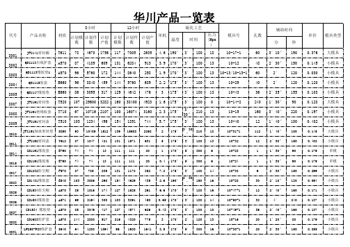
QD1115胶套
E660 96 3840 459 144 5760 689 2.2 175° 3′ 180 13
10-29
QD1117橡胶垫 E660 86 3095 317 129 4642 476
3 175° 3′ 180 13
10-43
JFZ191密封垫 T520 107 25600 3282 160 38400 4923 1.6 175° 3′ 180 0
E790
152
1364 187
227
2046
280
3.6 175° 2′ 120 13
10-11
9
8036
“□”67.8×63.5 ×2.3
E790
220
1979 271
330
2968
406
3.6 175° 2′ 120 13
10-10
9
8037 5×2
O形圈 F751 192 12288 525 288 18432 788 0.21 190° 2′ 120 13
大模具 小模具 小模具 小模具 小模具 大模具 小模具 小模具 大模具 小模具
单模 单模 小模具 小模具 小模具 小模具 小模具 小模具 小模具
8033
110J橡胶插头 G540 87 3142 255 131 4713 383 0.6 175° 3′7.8×64.5 ×2.3
1′30″ 90
1′30″ 90
2′30″ 150
2′10″ 130
2′40″ 160
4′
240
2′40″ 160
1′20″ 80
2′30″ 150
单价 模具类型
0.376 0.145 0.030 0.120 0.103 0.128 0.197 0.402 0.145 0.402 0.179 0.179 0.299 0.094 0.171 0.137 0.137 0.179 0.855
德国工业实际联系部件编号说明说明书

0460-256-12**
12 PIN
1.5 mm² 16 AWG 1.0 mm²
18 AWG 0.75 mm²
35 [156] 25 [111]
.222-.284 [5.64-7.21]
0460-215-16** 0462-209-16**
16 PIN 16 SOC
14 AWG 2.0 mm²
70 [311]
7 CYCLE TOOL TO OPEN HANDLES. REMOVE LOCK CLIP. RAISE AND ROTATE DIAL TO SELECT WIRE SIZE. REPLACE LOCK CLIP.
6 WHEN **= 31, PLATING IS GOLD. WHEN **=141, PLATING IS NICKEL.
3 USE 1.5 SETTING FOR THIS PART WITH 14 AWG.
2 CAUTION: NEVER CLOSE TOOL ON GAGE G454. CLOSE TOOL FIRST AND THEN INSERT GAGE.
1 USE GAGE G454 IN DCHECK WEAR ANNUALLY. CHECK
1.5 mm² 16 AWG 1.0 mm²
18 AWG 0.75 mm²
4.0 mm² 12 AWG 3.0 mm² 2.5 mm²
35 [156] 25 [111]
.222-.284 [5.64-7.21]
75 [334]
.222-.284 [5.64-7.21]
SLOTTED (SPLIT) PIN 11
NOTES: UNLESS OTHERWISE SPECIFIED
B18系列产品说明书

*(XXX)CO
4
MC/AC
4
1/2" [13] & 3/4" [19]
Attaches to 1/8" [3] through 1/4" [6] flange.
4
1" [25]
4
MC/AC
4
1/2" [13] & 3/4" [19]
other purpose.
NOTE: All load ratings are for static conditions and do not account for dynamic loading such as wind, water or seismic loads, unless otherwise noted.
Pentair, CADDY, ERICO CADWELD, ERICO CRITEC, ERICO, ERIFLEX, and LENTON are owned by Pentair or its global affiliates. All other trademarks are the property of their respective owners. Pentair reserves the right to change specifications without prior notice.
CADDY B18 series with threaded rod going through both
the B18 and the box, this single support is appropriate.
C2003系列 changjiang 连接器商品说明书

1.90±0.25
0.20 SEC:A-A
2.00±0.25
8.73±0.25 0.84
1.30 0.65
5.54±0.20
A B C
A B C
1.00
0.50
0.72 0.40
1.50±0.25 SEC:B-B
1.50±0.25
1.60±0.25
2.00mm pitch Crimp Terminal
2.00mm pitch wire to wire connector
0.20 2.40±0.25
2.68±0.25
3.00±0.25 0.80
1.30
1.50±0.25
A
A
B
B
1.50±0.20
7.50±0.25
1.60±0.25
SEC:A-A
B
2.00
5.70
4.00
7.70
6.00
9.70
8.00
11.70
10.00
13.70
14.00
17.70
18.00
21.70
Unit: mm
Reference Informations: *Material:Nylon 66,UL94V-0 *Suitable CJT C2003MB-T series Terminal *Mates with CJT C2003HFB-XP series Housing and C2003SB-XP series Seal *Color:White
5.20±0.20 9.20±0.25
2.10±0.20
2.70±0.25
UPC3241TB-E3-A;UPC3241TB-A;UPC3241TB-EVAL-A;中文规格书,Datasheet资料

MMIC
MEDIUM
OUTPUT
POWER
PO (sat) (dBm) + 9.0 (0.9 GHz) + 8.5 (1.9 GHz) + 11.0 (0.9 GHz) + 8.0 (1.9 GHz) + 12.5 (0.9 GHz) + 11.0 (1.5 GHz) + 9.5 (0.9 GHz) + 9.0 (1.9 GHz) + 9.0 (2.4 GHz) + 11.0 (0.9 GHz) + 10.5 (1.9 GHz) + 10.0 (2.4 GHz) + 12.5 (1.0 GHz) + 10 (2.2 GHz)
This device exhibits low noise figure and high power gain characteristics. This IC is manufactured using our UHS0 (Ultra High Speed Process) bipolar process.
Parameter Supply Voltage Total Circuit Current Power Dissipation Operating Ambient Temperature Storage Temperature Input Power Symbol VCC ICC PD TA Tstg Pin TA = +25°C Conditions TA = +25°C, pin 4 and 6 TA = +25°C, pin 4 and 6 TA = +85C Note Ratings 4.0 55 270 40 to +85 55 to +150 10 Unit V mA mW °C °C dBm
航洋压敏电阻(型号很全)

53
6.0
5.0
1000
14K330 33
30-36
20
26
65
7.5
6.0
1000
14K390 39
35-43
25
31
77
8.6
7.0
1000
高
14K470 47
42-52
30
38
93
10.
8.5
1000
能
14K560 56
50-62
35
45
110
11.
10
1000
I
14K680 68
61-75
40
100
200
20
14.5
3500
高
10K151 150 135-165 95 125
250
25
18
3500
能
II
10K181 180 162-198 115 150
300
31
21
3500
10K201 200 185-225 130 170
340
35
25
3500
型
10K221 220 198-242 140 180
航洋电子 压敏电阻器
普
通 浙江黄岩航洋电子有限公司
型 Zhejiang Huangyan Hangyang Electronics Co.,Ltd.
高 MYG 型氧化锌压敏电阻器
能 I 型
功能
相关标准
高
●过电压保护、防雷、抑制浪涌电流、高压灭 ●IEC61051
能
弧、消噪等
II
●UL1449 ●VDE CECC42000
UPC8181TB-E3-A;UPC8181TB-EVAL-A;中文规格书,Datasheet资料

TYPICAL PERFORMANCE CURVES (Unless otherwise specified, TA = 25˚C)
CIRCUIT CURRENT vs. SUPPLY VOLTAGE
40 No Signal
35
CIRCUIT CURRENT vs. OPERATING AMBIENT TEMPERATURE
Input Return Loss,
f = 0.9 GHz f = 1.9 GHz f = 2.4 GHz
Output Return Loss,
f = 0.9 GHz f = 1.9 GHz f = 2.4 GHz
UNITS dBm
dBm dB dB
UPC8181TB S06
MIN
TYP
MAX
+5.5
SYMBOLS
PARAMETERS AND CONDITIONS
PO(1dB) PO(SAT)
RLin RLout
1 dB Gain Compression Output Level, f = 0.9 GHz f = 1.9 GHz f = 2.4 GHz
Saturated Output Power Level, f = 0.9 GHz, PIN = -5 dBm f = 1.9 GHz, PIN = -5 dBm f = 2.4 GHz, PIN = -5 dBm
+8.0
–
+4.5
+7.0
–
+4.5
+7.0
–
–
+9.5
–
–
+9.0
–
–
+9.0
–
易安电子产品说明书

Eaton 189884Eaton Moeller® series PKZM01 Motor-protective circuit-breaker, 660 V 690 V: 0.55 kW, Ir= 0.63 - 1 A, IP20General specificationsEaton Moeller® series PKZM01 Motor-protective circuit-breaker189884PKZM01-1-EA401508187880293 mm 90 mm 45 mm 0.261 kgCE Marked RoHS conformProduct NameCatalog Number Model Code EANProduct Length/Depth Product Height Product Width Product Weight Compliances0.25 kW0.63 AThermomagnetic15.5 A0.12 kWBuilt-in device fixed built-in technique Phase failure sensitiveScrew connectionThree-pole690 V50 kA1 A5.33 W15.5 A1 A690 VPush button Motor Starters in System xStart - brochureSave time and space thanks to the new link module PKZM0-XDM32MESwitching and protecting motors - catalogProduct Range Catalog Switching and protecting motorseaton-manual-motor-starters-characteristic-characteristic-curve-008.eps eaton-manual-motor-starters-characteristic-characteristic-curve-009.eps eaton-manual-motor-starters-characteristic-characteristic-curve-005.epsDA-DC-00004883.pdfeaton-manual-motor-starters-circuit-breaker-pkzm01-dimensions.eps eaton-manual-motor-starters-circuit-breaker-pkzm01-3d-drawing-002.epseaton-general-ie-ready-dilm-contactor-standards.epseaton-manual-motor-starters-mounting-3d-drawing-002.epsDA-CE-ETN.PKZM01-1-EAIL034045ZUWIN-WIN with push-in technologyDA-CD-pkzm01DA-CS-pkzm01Rated operational power at AC-3, 380/400 V, 50 Hz Overload release current setting - minSwitch off techniqueAdjustment range undelayed short-circuit release - min Rated operational power at AC-3, 220/230 V, 50 Hz Device constructionFunctionsElectrical connection type of main circuitNumber of polesRated operational voltage (Ue) - minRated short-circuit breaking capacity Icu at 400 V AC Rated uninterrupted current (Iu)Power lossAdjustment range undelayed short-circuit release - max Overload release current setting - maxRated operational voltage (Ue) - maxActuator typeDegree of protection BrochuresCatalogsCharacteristic curveDeclarations of conformity DrawingseCAD modelInstallation instructions Installation videosmCAD modelEaton Corporation plc Eaton House30 Pembroke Road Dublin 4, Ireland © 2023 Eaton. All Rights Reserved. Eaton is a registered trademark.All other trademarks areproperty of their respectiveowners./socialmediaIP20。
- 1、下载文档前请自行甄别文档内容的完整性,平台不提供额外的编辑、内容补充、找答案等附加服务。
- 2、"仅部分预览"的文档,不可在线预览部分如存在完整性等问题,可反馈申请退款(可完整预览的文档不适用该条件!)。
- 3、如文档侵犯您的权益,请联系客服反馈,我们会尽快为您处理(人工客服工作时间:9:00-18:30)。
•SUPPLY VOLTAGE:V CC = 2.7 to 3.3 V•CIRCUIT CURRENT:I CC = 23.0 mA TYP at V CC = 3.0 V•POWER GAIN:G P = 19.0 dB TYP at f = 0.9 GHz G P = 21.0 dB TYP at f = 1.9 GHz G P = 22.0 dB TYP at f = 2.4 GHz •MEDIUM OUTPUT POWER:P O(1dB) = +8.0 dBm TYP at f = 0.9 GHz P O(1dB) = +7.0 dBm TYP at f = 1.9 GHz P O(1dB) = +7.0 dBm TYP at f = 2.4 GHz•UPPER LIMIT OPERATING FREQUENCY:f U = 4.0 GHz TYP at 3 dB bandwidth (Standard value)•HIGH-DENSITY SURFACE MOUNTING:6-pin super minimold package (2.0 x 1.25 x 0.9 mm)FEATURES3 V, SILICON MMICMEDIUM OUTPUT POWER AMPLIFIERFOR MOBILE COMMUNICATIONSUPC8181TBDESCRIPTIONThe UPC8181TB is a silicon Monolithic Microwave Integrated Circuit designed as an amplifier for mobile communications.This IC operates at 3 volts. The medium output power is suitable for RF-TX of mobile communication systems.This IC is manufactured using NEC's 30 GHz f max UHS0 (Ultra High Speed process) silicon bipolar process. This process uses direct silicon nitride passivation film and gold electrodes.These materials can protect the chip surface from pollution and prevent corrosion/migration. This IC has excellent perfor-mance, uniformity, and reliability.NEC's stringent quality assurance and test procedures ensurethe highest reliability and performance.APPLICATIONS• Buffer amplifiers for 1.9 GHz to 2.4 GHz mobile communication systems.G PN FV CC = 3.0 V3025201510503450.10.31.03.0G a i n , G P (d B )Frequency, f (GHz)NOISE FIGURE, POWER GAIN vs.FREQUENCYELECTRICAL CHARACTERISTICS(T A = 25°C, V CC = V OUT = 3.0 V, Z S = Z L = 50Ω)PART NUMBER UPC8181TBPACKAGE OUTLINES06SYMBOLSPARAMETERS AND CONDITIONSUNITS MIN TYP MAX I CC Circuit Current (no signal)mA –23.030.0G PPower Gain,f = 0.9 GHz dB16.019.022.0f = 1.9 GHz 18.021.024.0f = 2.4 GHz 19.022.025.0NF Noise Figure, f = 0.9 GHz dB– 4.5 6.0f = 1.9 GHz – 4.5 6.0f = 2.4 GHz – 4.5 6.0f U Upper Limit Operating Frequency, 3 dB down below from gain at f = 0.1 GHz GHz – 4.0–ISLIsolation,f = 0.9 GHz dB28.033.0–f = 1.9 GHz 27.032.0–f = 2.4 GHz26.531.5–N o i s e F i g u r e , N F (d B )元器件交易网UPC8181TBTYPICAL PERFORMANCE CURVES (Unless otherwise specified, T A = 25˚C)CIRCUIT CURRENT vs.OPERATING AMBIENT TEMPERATUREOperating Ambient Temperature, T A (°C)C i r c u i t C u r r e n t , I C C (m A )CIRCUIT CURRENT vs. SUPPLY VOLTAGEC i r c u i t C u r r e n t , I C C (m A )Supply Voltage, V CC (V)No Signal 4035302025151050012344035302025151050-60-40-200+20+40+60+80+100No Signal V CC = 3.0 VELECTRICAL CHARACTERISTICS (cont.)(T A = 25°C, V CC = V OUT = 3.0 V, Z S = Z L = 50Ω)PART NUMBER UPC8181TBPACKAGE OUTLINES06SYMBOLS PARAMETERS AND CONDITIONSUNITS MIN TYP MAX P O(1dB)1 dB Gain Compression Output Level,f = 0.9 GHz dBm+5.5+8.0–f = 1.9 GHz +4.5+7.0–f = 2.4 GHz+4.5+7.0–P O(SAT)Saturated Output Power Level,f = 0.9 GHz, P IN = -5 dBm dBm–+9.5–f = 1.9 GHz, P IN = -5 dBm –+9.0–f = 2.4 GHz, P IN = -5 dBm –+9.0–RL in Input Return Loss,f = 0.9 GHz dB4.57.5–f = 1.9 GHz 7.510.5–f = 2.4 GHz 8.011.0–RL out Output Return Loss, f = 0.9 GHz dB6.09.0–f = 1.9 GHz7.010.0–f = 2.4 GHz9.012.0–SYMBOLSPARAMETERS UNITS MIN TYP MAX V CCSupply Voltage 1V2.73.03.3ABSOLUTE MAXIMUM RATINGS 1SYMBOLSPARAMETERS UNITS RATINGSV CC Supply Voltage 2V 3.6I CC Total Cicuit Current mA 60P D Power Dissipation 3mW 270T A Operating Ambient °C -40 to +85Temperature T STG Storage Temperature °C -55 to +150P INInput Power 4dBm+10Notes:1.Operation in excess of any one of these conditions may result in permanent damage.2.T A = 25°C, pins 4 and 6.3.Mounted on a double-sided copper clad 50x50x1.6 mm epoxy glass PWB, T A = +85°C.4.T A = +25 °CRECOMMENDEDOPERATING CONDITIONSNote:1.Same voltage applied to pins 4 and 6元器件交易网UPC8181TBTYPICAL PERFORMANCE CURVES (Unless otherwise specified, T A = 25˚C)I s o l a t i o n , I S O L (d B )Frequency, f (GHz)ISOLATION vs. FREQUENCY-10-20-30-400.10.3 1.0 3.0V CC = 3.0 V+15+10+5-5-10-15-20-25-30-50-40-30-20-100+10f = 0.9 GHz V CC = 3.0 VO u t p u t P o w e r , P O U T (d B m )Input Power, P IN (dBm)OUTPUT POWER vs. INPUT POWERINPUT RETURN LOSS, OUTPUT RETURN LOSS vs.FREQUENCYI n p u t R e t u r n L o s s , R L I N (d B )Frequency, f (GHz)O u t p u t R e t u r n L o s s , R L O U T (d B m )-5-10-150.10.31.03.0O u t p u t P o w e r , P O U T (d B m )Input Power, P IN (dBm)OUTPUT POWER vs. INPUT POWER+15+10+5-5-10-15-20-25-30-50-40-30-20-100+10f = 1.9 GHz V CC = 3.0 VO u t p u t P o w e r , P O U T (d B m )Input Power, P IN (dBm)OUTPUT POWER vs. INPUT POWER+15+10+5-5-10-15-20-25-30-50-40-30-20-100+10f = 2.4 GHz V CC = 3.0 VS a t u r a t e d O u t p u t P o w e r , P O (s a t ) (d B m )SATURATED OUTPUT POWER vs.FREQUENCY+12+10+8+6+4+200.10.31.03.0Frequency, f (GHz)UPC8181TBTYPICAL PERFORMANCE CURVES (Unless otherwise specified, T A = 25˚C)Output Power of Each Tone, P OUT (dBm)T h i r d O r d e r I n t e r m o d u l a t i o n D i s t o r t i o n , I M 3 (d B c )THIRD ORDER INTERMODULATION DISTORTION vs.OUTPUT POWER OF EACH TONE-10-20-30-40-50-60-15-10-5+5+10+15Output Power of Each Tone, P OUT (dBm)T h i r f O r d e r I n t e r m o d u l a t i o n D i s t o r t i o n , I M 3 (d B c )THIRD ORDER INTERMODULATION DISTORTION vs.OUTPUT POWER OF EACH TONE-15-10-50+5+10-10-20-30-40-50-60Output Power of Each Tone, P OUT (dBm)T h i r f O r d e r I n t e r m o d u l a t i o n D i s t o r t i o n , I M 3 (d B c )THIRD ORDER INTERMODULATION DISTORTION vs.OUTPUT POWER OF EACH TONE-15-10-50+5+10-10-20-30-40-50-60V CC = V OUT = 3.0 V, I CC = 23.0 mA FREQUENCYS 11S 21S 12S 22GHz MAG ANG MAG ANG MAG ANG MAG ANG K 0.10.452-2.79.078-2.00.020 4.30.338-1.6 1.890.20.467-5.79.098-4.90.021 4.20.346-2.1 1.730.30.470-7.59.143-6.90.0218.20.344-1.0 1.720.40.460-9.39.237-10.10.0219.80.335-2.7 1.750.50.438-11.59.284-11.90.02111.40.328-4.8 1.840.60.415-14.79.442-14.60.0228.10.337-7.5 1.730.70.397-18.69.670-17.00.02211.50.350-7.9 1.720.80.395-22.49.897-19.70.02216.30.354-6.8 1.690.90.399-25.610.166-22.70.02314.50.342-6.0 1.561.00.404-28.110.496-26.00.02213.40.331-7.9 1.601.10.396-29.010.903-29.00.02318.00.332-10.8 1.481.20.394-28.511.329-32.80.02516.60.353-13.4 1.331.30.385-28.011.895-37.90.02517.40.376-14.3 1.261.40.368-28.812.145-42.40.02422.00.374-15.0 1.281.50.347-29.512.356-47.60.02524.30.361-16.3 1.281.60.335-30.912.670-51.80.02620.60.356-19.3 1.221.70.327-31.512.966-56.40.02421.40.356-22.0 1.291.80.328-31.213.410-61.40.02623.20.366-23.9 1.171.90.327-29.413.722-66.80.02727.50.367-25.6 1.112.00.325-29.414.151-72.30.02624.60.369-28.5 1.112.10.316-28.514.412-78.10.02826.40.363-31.7 1.052.20.295-29.414.747-84.10.02726.50.361-35.4 1.082.30.288-30.815.144-90.30.02927.50.359-37.1 1.022.40.291-34.115.463-97.40.02927.10.346-39.0 1.012.50.303-38.315.264-104.60.02927.70.323-40.6 1.042.60.317-41.115.137-112.60.02825.50.303-43.1 1.092.70.335-41.314.774-119.80.02925.50.294-43.9 1.072.80.349-41.014.176-127.70.03125.00.299-43.0 1.032.90.347-39.413.710-133.70.02932.90.304-41.3 1.093.00.345-43.212.808-139.80.02924.80.317-44.9 1.153.10.341-45.412.313-146.00.03128.90.325-46.7 1.133.20.331-47.911.587-149.30.02931.60.318-48.7 1.253.30.323-49.811.003-154.50.03131.2 0.315-52.1 1.273.40.311-52.110.638-157.70.03129.50.307-56.1 1.323.50.302-52.610.228-162.00.02932.50.302-60.0 1.443.60.289-54.99.985-166.50.03031.40.303-63.7 1.473.70.266-56.59.543-170.10.03039.60.301-65.1 1.543.80.253-61.59.184-174.50.03134.10.294-67.5 1.553.90.238-65.68.816-177.70.03036.20.275-68.8 1.714.00.238-70.78.488178.20.03238.90.270-71.0 1.704.10.244-74.08.186174.30.03237.00.266-75.11.75TYPICAL SCATTERING PARAMETERS (T A = 25˚C)Coordinates in Ohms Frequency in GHzV CC = V OUT = 3.0 V, I CC = 23S11S22UPC8181TBUPC8181TB(Pin Voltage is measured at V CC = 3.0 V)APPLICATION EXAMPLE (Digital Cellular Telephone)UPC8181TBOUTLINE DIMENSIONS (Units in mm)6-PIN SUPER MINIMOLDLEAD CONNECTIONS1.INPUT2.GND3.GND4.OUTPUT5.GND6.V CC(Top View)(Bottom View)321456C 3E3214560 t-0.05-0.05TEST CIRCUITOUT*10 nH for f = 2 GHzAPPLICATION BOARD1. double sided copper clad GETEK board (H = .028, εr = 4.2.)2. Back side: GND pattern.3. Solder plated on patterns.4. o O : Through holes.PART NUMBER PACKAGE QUANTITY UPC8181TB-E36-pin super minimold3kpcs/ReelORDERING INFORMATIONNote: Embossed tape 8 mm wide. Pins 1,2,3 face tape perforation side.EXCLUSIVE NORTH AMERICAN AGENT FOR NEC RF, MICROWAVE & OPTOELECTRONIC SEMICONDUCTORS• Headquarters • 4590 Patrick Henry Drive • Santa Clara, CA 95054-1817 • (408) 988-3500 • Telex 34-6393 • FAX (408) 988-0279Internet: 04/24/2002Life Support ApplicationsThese NEC products are not intended for use in life support devices, appliances, or systems where the malfunction of these products can reasonably be expected to result in personal injury. The customers of CEL using or selling these products for use in such applications do so at their own risk and agree to fully indemnify CEL for all damages resulting from such improper use or sale.元器件交易网。