PC-碳纳米管复合材料制备与表征
碳纳米材料的制备与表征

碳纳米材料的制备与表征碳纳米材料是一类由纳米级碳结构构成的材料,具有广泛的应用前景。
其制备与表征是研究领域的关注点之一,本文将介绍碳纳米材料的制备方法以及常用的表征技术。
一、碳纳米材料的制备1. 碳纳米管的制备碳纳米管是一种具有纳米级管状结构的碳材料。
常用的制备方法有化学气相沉积、电化学沉积和机械法。
化学气相沉积是最常见的方法,通过在高温下将碳源气体进行分解,使其在催化剂表面生成碳纳米管。
电化学沉积是利用电解质溶液中的电流控制碳纳米管的形成。
机械法则是通过机械剥离或拉伸碳纤维等方式来获得碳纳米管。
2. 石墨烯的制备石墨烯是一种由碳原子构成的二维材料,具有良好的导电性和光学透射性。
石墨烯的制备方法主要包括机械剥离、化学气相沉积和化学剥离。
机械剥离是最早的方法,通过对石墨进行化学氧化后再进行剥离得到。
化学气相沉积则是在金属催化剂的表面上将碳源气体分解生成石墨烯。
化学剥离则是通过对石墨化合物进行化学反应,将其转化为石墨烯。
3. 碳量子点的制备碳量子点是一种具有纳米级尺寸的碳化合物颗粒,具有荧光性和电化学性能。
常用的制备方法有氧化法、溶剂热法和微乳液法。
氧化法是将含碳化合物溶解于酸性溶液中进行氧化反应,生成碳量子点。
溶剂热法则是将碳源溶解在有机溶剂中,进行高温热解得到碳量子点。
微乳液法是将碳源溶解在适当的表面活性剂溶液中,通过控制反应条件得到碳量子点。
二、碳纳米材料的表征1. 扫描电子显微镜(SEM)SEM是一种常用的表征碳纳米材料形貌和表面形貌的技术。
利用SEM,可以观察到碳纳米材料的表面结构、孔隙结构以及分散性等特征。
2. 透射电子显微镜(TEM)TEM是一种可以获得碳纳米材料高分辨率图像的技术。
通过TEM,可以观察到碳纳米材料的晶体结构、晶格参数以及异质结构等细节。
3. X射线衍射(XRD)XRD是一种用于分析碳纳米材料晶体结构的技术。
通过分析X射线材料与物质相互作用引起的衍射图案,可以确定碳纳米材料的晶体结构、晶面取向以及晶体尺寸等信息。
一种PC纳米复合材料及其制备方法[发明专利]
![一种PC纳米复合材料及其制备方法[发明专利]](https://img.taocdn.com/s3/m/df0308dd580216fc710afd6f.png)
专利名称:一种PC纳米复合材料及其制备方法
专利类型:发明专利
发明人:马永梅,郑鲲,张京楠,曹新宇,叶钢,尚欣欣,卢佳欣申请号:CN201810184816.2
申请日:20180306
公开号:CN110229490A
公开日:
20190913
专利内容由知识产权出版社提供
摘要:本发明涉及纳米复合材料领域,具体地说,涉及一种PC纳米复合材料,PC纳米复合材料是由混料经熔融共混制得;混料包括PC,PC颗粒上结合有纳米材料和液体介质。
还涉及一种PC纳米复合材料的制备方法,包括:(1)将纳米材料、液体介质混合,制得膏状物;(2)将膏状物和PC混合,使膏状物粘覆在PC颗粒表面,制得混料;(3)将混料熔融共混,制得纳米复合材料。
本发明的混料加入到挤出机等设备中后不会打滑,可直接制备纳米复合材料,无需在制备过程中加入其它物质,便于生产加工,且避免了现有技术中液体介质过早气化导致的纳米复合材料性能较差的问题,经实验发现,相比于现有技术,本发明的混料制得的纳米复合材料性能更加优越。
申请人:中国科学院化学研究所
地址:100190 北京市海淀区中关村北一街2号中国科学院化学研究所
国籍:CN
代理机构:北京元中知识产权代理有限责任公司
代理人:王明霞
更多信息请下载全文后查看。
基于碳纳米管的生物材料制备与表征及生物医学应用研究的开题报告
基于碳纳米管的生物材料制备与表征及生物医学应用研究的开题报告一、选题背景和研究意义基于碳纳米管的生物材料近年来备受关注,因其独特的物理化学性质和生物相容性,被广泛应用于生物医学领域。
碳纳米管可以用于制备纳米生物传感器、生物成像、药物输送等领域,具有极高的应用价值。
在实际应用中,大多数碳纳米管的制备方法涉及到一定程度的处理和改装,这种处理和改装也让碳纳米管装置具有了不同应用领域的功能。
尽管在这几年里,碳纳米管的制备技术已经有了很大的进展,但是如何在医学领域合理、安全、高效地应用碳纳米管,仍是一个亟待解决的问题。
本研究旨在探究基于碳纳米管的生物材料制备与表征及生物医学应用,从纳米尺度入手,研究碳纳米管在生物医学应用上的独特性质,并通过制备、表征、评价及实验验证,建立碳纳米管在生物医学领域应用的理论和技术基础,为其未来的广泛应用奠定基础。
二、研究内容和方法本研究的主要内容包括:1. 碳纳米管的制备方法研究:综观碳纳米管的制备技术,选择最优制备方法,以得到高质量的碳纳米管。
2. 材料表征研究:借助扫描电镜(SEM)、透射电镜(TEM)、X射线衍射(XRD)等不同表征手段,对制备的碳纳米管进行结构表征和物理化学性质分析。
3. 生物相容性评价研究:通过细胞毒性测试、细胞摄取实验、药物释放等实验评价碳纳米管的生物相容性和生物安全性,为其在医学领域的应用提供保障。
4. 生物医学应用研究:选择代表性的生物医学应用领域,如生物成像、药物输送、肿瘤治疗等,探索碳纳米管在这些应用领域中的应用优势和局限性。
研究方法主要包括:1. 碳纳米管的制备方法与表征:采用化学气相沉积(CVD)方法制备碳纳米管,并采用SEM、TEM、XRD等方法对其进行表征。
2. 生物相容性评价:采用细胞毒性测试、细胞摄取实验,以及药物释放等实验,评价碳纳米管的生物相容性和生物安全性。
3. 生物医学应用研究:选取代表性应用领域,研究碳纳米管在这些领域的应用及其局限性。
碳纳米管pc导电

碳纳米管pc导电
碳纳米管PC导电材料是一种将碳纳米管添加到聚碳酸酯(PC)基础材料中的复合材料。
这种材料利用了碳纳米管的优异力学、电学和导热性能,以改善PC材料的性能。
碳纳米管具有高强度、高刚度和高导电性,可以增加聚碳酸酯材料的强度和刚度,并提高其导电性能。
此外,碳纳米管还具有一些特殊的电学性质,如大范围的离域π键和良好的导电性能。
这些性质使得碳纳米管PC在电子、防静电保护等领域有广泛的应用前景。
在制备碳纳米管PC导电材料时,需要选择合适的碳纳米管和聚碳酸酯材料,并控制制备工艺,以确保碳纳米管在聚碳酸酯基体中均匀分散并发挥良好的导电性能。
此外,还需要对碳纳米管PC复合材料的性能进行测试和表征,以确保其满足实际应用的要求。
总之,碳纳米管PC导电材料是一种具有广泛应用前景的新型复合材料,其制备和应用需要综合考虑材料性能、制备工艺和应用需求等多个方面。
碳纳米管及其复合材料的制备与性能研究进展

是近 来 研究的 年 人们 一个热 题f2一〕 化处理 点问 0 ,纯 .
后的碳纳米管, 不仅纯度和分散性有了很大的提高, 而且表面结构也发生了变化, 碳纳米管的端帽被打 开, 曲折点断裂处以及其他不饱和的碳原子被氧化 为带有经基、 拨基和梭基等有机极性的官能基团, 利 用这些官能基团和非共价键、 侧壁、 二键堆垛、 豆荚 型缺陷等进行功能化修饰, 可使其表面接枝多种官 能团, 引人增溶基团, 提高碳纳米管与聚合物之间的
壁碳纳米管的直径一般为I nm 一 nm, 6 大于6 nm后 特别不稳定, 易塌陷, 长度为几百纳米至几微米, 多壁 碳纳米管的 距约为0.3 nm, 层间 4 直径为几纳米至几 十纳米, 长度一般在微米量级, 最长者可达数毫米. 由 于碳纳米管具有较大的长径比, 所以可以把其看成准 一维纳米材料. 碳纳米管并不总是笔直的, 局部区域
Key wor d :carbon nanotubes ; pr par ion ; modif ca ion s e a t i t
0
引言
会出现凸凹现象, 这是因 为在石墨烯片层六元环编织 过程中出现了五元环和七元环, 产生了大小不同的张
碳纳米管是由碳原子形成的石墨片层卷成的无 缝、 中空的管体, 是一种新型的纳米材料. 依据石墨片 层的多少可以分为单壁碳纳米管和多壁碳纳米管. 单
力 致〔 〕 合物材料具有密度小、 所 ‘.聚 一 耐腐蚀、 易加
工、 韧性好、 耐磨等优良 特性, 但强度、 刚度不够, 耐热 性差, 尺寸稳定性不好、 易老化. 而碳纳米管具有许多 优异的性能, 如超高的力学强度、 优良的化学热稳定 性、 较好的导电性及电磁屏蔽效应等. 二者复合以后 加工简便, 效果明显, 优势互补, 可以用来制造不同于 常规高分子聚合物的增强材料、 导电材料、 信息材料、 隐身材料、 生物医用材料等, 在复合材料制造领域中
碳纳米管的制备和表征研究
碳纳米管的制备和表征研究碳纳米管是一种非常重要的纳米材料,由于其具有优异的物理和化学性质,能够广泛应用于电子、化学、生物和医学等领域,成为了当今最热门的研究课题之一。
本文将介绍碳纳米管的制备和表征研究,旨在尽可能全面深入地介绍它的相关研究进展。
一、碳纳米管的制备方法碳纳米管的制备方法主要有以下几种:1. 等离子体增强化学气相沉积法该方法先用金属作为催化剂,在氧化镁或氧化铝的载体上制备成催化剂阵列,通过引入碳源和氢气,使用等离子体的方式来生成碳纳米管。
2. 化学气相沉积法该方法将催化剂和碳源同时放置在反应器内,不用外加能量,通过化学反应来制备碳纳米管。
3. 化学还原-热解法该方法先用催化剂将氧化石墨烯还原为石墨烯,然后利用热解技术进行碳化反应,制备碳纳米管。
以上三种方法是主流的制备碳纳米管的方法,但随着研究的深入,其它方法,如水热合成法、溶液-液相界面法等也逐渐被应用于制备碳纳米管。
二、碳纳米管表征技术为了对制备的碳纳米管进行表征和刻画,研究人员开发出了各种表征技术来研究其结构和性质,下面我们来介绍一些常用的表征技术:1. 透射电子显微镜(TEM)透射电子显微镜是最常用的碳纳米管表征技术之一,通过它可以直观的获得碳纳米管的观察图像。
2. 扫描电子显微镜(SEM)与TEM不同,扫描电子显微镜可以观察到碳纳米管的表面形貌,并能够获得表面形貌的三维结构图像。
3. 拉曼光谱(Raman)拉曼光谱具有非常高的灵敏性和分辨率,能够通过对碳纳米管的拉曼光谱图像进行功率谱分析,可以获得碳纳米管的结构、相互作用和物理特性等信息。
4. X射线粉末衍射(XRD)利用X射线的衍射实验,可以得到碳纳米管的晶格结构,晶格常数以及结晶度等信息。
5. 热重分析(TGA)热重分析可以帮助我们展现出材料在温度变化下的失重信息,从而推断出碳纳米管的热稳定性和热分解温度等相关信息。
以上技术对于制备和表征碳纳米管都有非常大的帮助,不同的表征方法可以从不同角度来对碳纳米管进行综合分析,有助于我们更好地了解碳纳米管的结构和性质。
碳纳米管复合材料研究进展

碳纳米管复合材料研究进展碳纳米管(Carbon nanotubes,CNTs)是由碳原子构成的长管状结构,直径在纳米级别范围内,具有优异的力学性质、电学性质和热学性质等特性。
碳纳米管的应用极其广泛,涉及到材料、化学、电子、生物和医学等领域。
在材料领域,由碳纳米管复合材料制成的材料在机器人、汽车、飞机、结构材料等方面具有广泛的应用前景。
本文将就碳纳米管复合材料研究进展,从制备、性质及其应用等方面进行论述。
一、制备方法碳纳米管复合材料的制备方法有许多种,包括机械法、溶液法、气相法、离子液体法等。
其中机械法制备的碳纳米管复合材料具有制备工艺简便、低成本、易扩展等优点,但是因为机械法的制备方式较为粗糙,可能会导致制备的复合材料的性能不佳。
离子液体法制备的碳纳米管复合材料具有制备工艺简便、成品纯度高等优势,但是由于离子液体具有较大的粘度,可能限制了碳纳米管的扩散,并形成束缚作用,从而影响复合材料的性能。
相比之下,气相法制备的碳纳米管具有制备工艺简单、制备效率高、碳纳米管纯度高等优势,但是气相法制备的碳纳米管需要高分辨率的仪器进行纯化处理,且气相法制备出的碳纳米管质量与管径分布不均匀。
二、材料性质碳纳米管复合材料具有优异的力学性质、电学性质和热学性质等。
碳纳米管复合材料的力学性能优于传统材料,其拉伸强度达到多千兆帕,弹性模量达到10万吨/立方厘米以上。
电学性质方面,碳纳米管的宽禁带结构使其表现出了金属和半导体的一些性质。
电学性质的优异性可用于电子器件的开发。
热学性质方面,碳纳米管的热传导性能突出,热扩散系数高达4000至6000W/mK左右,是金属的数倍。
然而,碳纳米管在制备和应用时也存在一些问题。
由于碳纳米管的外壳和内腔具有不同的物理结构,也导致了其结构多样化的特性。
复合材料内的碳纳米管方向性效应的强弱决定了复合材料的最终性能,因此研究碳纳米管在复合材料中的应用及取向问题至关重要。
同时,单根碳纳米管的直径和长度均较小,因此用于制备纳米复合材料时需要用到大量碳纳米管,制备过程的成本较高。
聚氨酯/碳纳米管复合材料的制备与表征

平板 硫 化 机 , L X B型 , 岛亚 东 橡 胶 集 团有 限 青
公司; 橡胶强力试验机 , M 40 , C T 24 深圳新 三思材料
检测 有 限 公 司 ; 态 力 学 分 析 ( MA) , MA 8 动 D 仪 D 93
型, 国T 美 A公 司 ; 描 电镜 ( E ,S 3 C型 , 扫 S M) JM. 5 日
聚氨酯 ( u) P 弹性体 有 良好 力学 、 工 性 能 和粘 加 结性能, 目前用 C T 增 强 P Ns u体 系 的导 电性研 究 还 不 多 。本研 究 采 用 预 聚体 法 制 备 了 P / N s复 U CT 合 材料 , 并对 其 导 电性 和力 学性 能进 行 了考察 。
MO A 交联 的 P / N s 合材 料 导 电性 能好 ; T C UC T 复 用 MP作 交联 剂制 备 的 P / N s 合 材料 的 力 学 UC T 复 性 能 明显低 于 以 MO A 为扩 链 剂 的 P / N s复合 材 料 的 力 学性 能 ; C UC T 随着 C T N s的加 入 ,U C T P/ Ns
本 电子公 司 ; 高 电阻测 试 仪 ,C 8型 , 超 P6 上海 精 密科 学仪 器有 限公 司 。
1 3 P / NT 复合材 料 的制 备 . U C s
将 C T 在 10 干燥 1 , Ns 5% 2h 密封保 存备 用 。 将 10g聚酯多 元 醇 和定 量 的 C T 混 合 物 加 0 Ns 入到备 有 搅 拌 器 、 度 计 的三 口瓶 中 , 真 空 度 为 温 在 00 a温 度 为 10 .9MP 、 2 %左 右 的条 件下 脱 水 2h 。降 温 至 4 % 时 , 入 2 D , 拌 , 慢 升 温 至 0 加 5 gT I搅 缓 8% , 8 0 在 0~8 %保 温 2h 使 其 和 T I 分 反 应 , 5 , D 充 再 真 空 脱 泡 0 5h左 右 , 得 N O 质 量 分 数 为 . 制 C 47 .%左 右 的 预 聚 物 ; 后 加 入 交 联 剂 2 C 然 6gMO A 或 1 MP, 0gT 搅拌 均匀 , 倒入 到 预热 好 的模 具 中 , 在 平 板硫 化机 中 10 硫 化 1 i, 模后 , 10 2% 0rn 脱 a 在 0 %
- 1、下载文档前请自行甄别文档内容的完整性,平台不提供额外的编辑、内容补充、找答案等附加服务。
- 2、"仅部分预览"的文档,不可在线预览部分如存在完整性等问题,可反馈申请退款(可完整预览的文档不适用该条件!)。
- 3、如文档侵犯您的权益,请联系客服反馈,我们会尽快为您处理(人工客服工作时间:9:00-18:30)。
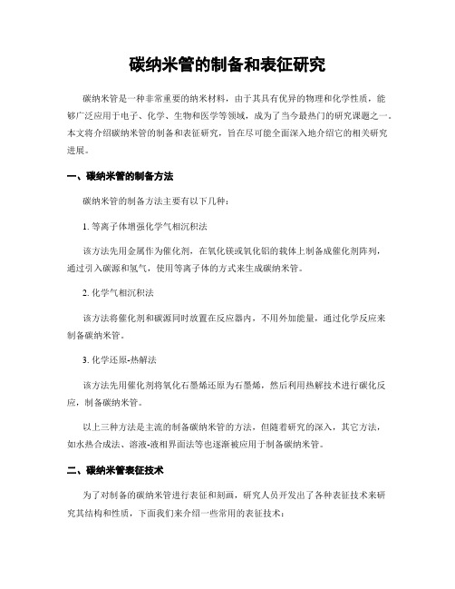
Short communicationFabrication and characterization of polycarbonate/carbonnanotubes compositesLi Chena,*,Xiu-Jiang Pang b ,Mei-Zhen Qu c ,Qing-tang Zhang c ,Bin Wang c ,Bai-Lan Zhang c ,Zuo-Long Yu c,*aKey Laboratory of Rubber-Plastics,Qingdao University of Science and Technology (QUST),Ministry of Education,Zhengzhou Road,Qingdao,Shandong 266042,ChinabDepartment of Chemistry and Molecular Engineering,QUST,Qingdao 266042,China cChengdu Institute of Organic Chemistry,Graduate School of Chinese Academy of Sciences,National Center for Nanoscience and Nanotechnology,Chengdu 610041,ChinaReceived 10November 2004;received in revised form 27August 2005;accepted 29August 2005AbstractPolycarbonate composites containing carbon nanotubes can be prepared through a method combined solution mixing and precipi-tation together.The surface chemical state of the purified carbon nanotubes was studied through X-ray photoelectron spectroscopy,and the state of carbon nanotubes in the composites through transmission electron microscopy and scanning electron microscopy.Results showed that some polar functional groups such as C A O,C @O and O A C @O were present on the surface of the purified carbon nanotubes,and carbon nanotubes coated with polycarbonate layers were well dispersed through the polycarbonate matrix.Ultrasound is supposed to play an important role in the uniform dispersion of carbon nanotubes into the polycarbonate solution and the formation of the composites.The preparing method is regarded as an easy way of producing polymer based nanocomposites on a large scale.Ó2005Elsevier Ltd.All rights reserved.Keywords:A:Carbon nanotubes;A:Polymer–matrix composites;B:Microstructures;D:Electron microscopy1.IntroductionSince the discovery of carbon nanotubes (CNTs),poly-mer based composites including CNTs have attracted considerable attention in the research and industrial com-munities,due to their good electrical conductivity,high stiffness and high strength at relatively low CNTs content [1–8].This can be attributed to the special electrical and mechanical properties of CNTs.For example,CNTs have diverse electrical properties,capable of acting as either con-ductors or semiconductors depending upon the chirialities of the CNTs [9,10].What is more,various studies have demonstrated that CNTs have moduli and strength levelsin the range 200–1000GPa and 200–900MPa,respectively [11,12].So,CNTs have been regarded as good candidates for producing new functional composites.A key issue in producing polymer/CNTs composites is how to achieve a homogeneous dispersion of CNTs in tar-get polymer base.Currently,three methods are commonly used to introduce CNTs into polymers:(1)solution mixing or film casting of suspensions of CNTs in dissolved poly-mer [13],(2)in situ polymerization of CNTs-polymer monomer mixture [14],and (3)mechanically melt mixing of CNTs with polymer melts [15].Studies using melt pro-cessed thermoplastic polymer/CNTs composites have been quite limited.The tendency of nanotubes to form aggre-gates may be minimized by appropriate application of shearing force during melt mixing.For example,Hag-genmueller et al.[4]applied a method that combined sol-vent casting and melt processing together to produce1359-835X/$-see front matter Ó2005Elsevier Ltd.All rights reserved.doi:10.1016/positesa.2005.08.009*Corresponding authors.Tel./fax:+8653284023977(L.Chen).E-mail address:chenli720516@ (L.Chen)./locate/compositesaComposites:Part A 37(2006)1485–1489films of poly(methyl methacrylate)(PMMA)containing single walled carbon nanotubes(SWNTs).Thefilms ob-tained by this melt processing technique had a more uni-form nanotube distribution than the castfilm and led to much better mechanical properties.Ferguson et al.[7]re-ported on kilogram quantities of polycarbonate(PC)-based nanotube formulations produced in a Buss Kneader.The results showed a better dispersion of thefibrils in as pro-duced composites.PO¨tschke et al.[16]examined the rheo-logical properties of multi-walled carbon nanotubes (MWNTs)filled PC nanocomposites formed by melt extrusion.Ultrasonic irradiation,as a new technology,has been widely used not only in chemical synthesis,but also in dis-persion,emulsifying,crushing,and activation of particles. By taking advantage of the multi-effects of ultrasound, the aggregates and entanglements of CNTs can be effec-tively broken down.Xia et al.[17,18]prepared polymer-encapsulated spherical inorganic nanoparticles through ultrasonic irradiation.Here,we produced PC based composites incorporating MWNTs by a combination of solution mixing and precip-itating,and examined the state of CNTs in the composites through transmission electron microscopy(TEM)and scanning electron microscopy(SEM).Results showed that CNTs were disentangled and well dispersed through the PC matrix,from which a tight interface binding can also be de-duced.X-ray photoelectron spectroscopy(XPS)was also used to study the surface chemical state of the purified MWNTs.2.ExperimentalMWNTs used were synthesized from methane via cata-lytically chemical vapor deposition(CCVD).A horizontal quartz glass reactor,30mm in diameter and1000mm in length,was used for the growth of MWNTs.The heat source was a tubular electric furnace.Temperatures were monitored using thermocouples coated with thin quartz tubes inserted into the reactor.The gasflow into the reac-tor was controlled by massflow controllers with an accu-racy of0.1ml for all gases.In all experiments,the reaction pressure was maintained at the ambient level. First,the catalysts were reduced from their oxidized state in aflow of H2(20ml/min)starting at room temperature and rising to1073K,then held at the latter temperature for0.5h.Then the reactor temperature was lowered to 973K for the reaction.After sweeping with N2gas,meth-ane was introduced into the reactor,passing over the cata-lyst at30ml/min for60min.After cooling to ambient temperature in aflow of N2,the products were collected. The as produced MWNTs were treated with acid to remove the remained catalyst particles and the support of catalysts. The as purified MWNTs were dried in a oven at150°C for 24h.The as produced MWNTs existed as agglomerates and curved intertwined entanglements[19]with an average diameter of20nm.The PC powder was obtained from Gang Yang-da Plastics Co.Ltd.Guang Zhou,China, and dried at110°C under vaccum prior to use.The production of the PC-based composites containing MWNTs was as follows:Firstly,10g PC powder was sol-ubilized in60ml chloroform(HCCl3);Secondly,under a power output of130W,the as purified MWNTs were dis-persed into the above solution of PC by sonicating at a fre-quency of20kHz for10min;Finally,precipitation was carried out to extract the PC/MWNTs composite particles which were then separated and fully dried in a vacuum oven.In this way,composites with different contents of MWNTs can be conveniently produced just by changing the amount of MWNTs incorporated.The as purified MWNTs and PC/MWNTs nanocom-posites were characterized by TEM using a JEM-100cx instrument with an accelerating voltage of20kV.The sam-ples were ultrasonicated in ethanol suspensions with ultra-sonic bath and then the dispersion was dropped on a copper grid to observe the morphology.Thermo-gravimetric analysis(TGA)was used to deter-mine the purity of purified CNTs,and a SEIKO EX-STAR6000was used to characterize weight loss during the oxidation of the samples in air heating to750°C at a rate of10°C/min.The surface state analysis of purified CNTs were per-formed by XPS employing a Kratos XSAM800spectrom-eter with Al K a(1.48keV)radiation.The system pressure was normally maintained at6.7·10À7Pa.The spectrome-ter was run infixed retarding ratio(FAT)mode at a pass energy12kV and15mA.All binding energies were re-ferred to the carbon1s(BE=284.6eV)peak for sample charging.SEM was also carried out on the fracture surface of the thin slice molded from the aforesaid PC/MWNT compos-ites by using a JSM-5900LV instrument with an accelerat-ing voltage of20kV.3.Results and discussionIt is well-known that most as produced CNTs contain some impurities such as amorphous carbon,fullerenes, Fig.1.TEM image of as purified MWNTs.1486L.Chen et al./Composites:Part A37(2006)1485–1489nanocrystalline graphite and catalyst particles,which were a serious impediment for CNTs to be directly used as func-tional filler in polymer based composites.Fig.1showed the TEM image of purified MWNTs in which the long inter-twined CNTs with a diameter of about 20nm were very clean and almost all impurities have been removed without destroying the basic structure of nanotubes.Thus,the puri-fication for MWNTs was effective.TGA results in Fig.2further indicated that the residue weight of purified MWNTs was rather low and the purity was about 98.0%.XPS analysis was applied to elucidate the surface state of the as purified MWNTs.Fig.3shows the XPS spectrum.According to the XPS studies about surface oxidized car-bon fibers [20,21],activated carbons [22,23],carbon black [24],and carbon nanotubes [25],the broader C 1s peak re-gion at 284.6eV could be fitted to four line shapes with binding energies at 285.024,286.620,288.950,291.070eV.These different binding energy peaks were assigned to C A C at 285.024eV,C A O at 286.620eV,C @O at 288.950eV and O A C @O at 291.070eV [26].So,in addition to the C A C groups,the surface of as purified MWNTs still contained other carbon-based surface polar oxygenatedgroups which were beneficial to the combination with PC matrix.These surface polar functional groups mainly come from the oxidation in its purification process.From the above results,the total area of the C 1s peak region of the MWNTs sample consists of 69.79%C A C,18.55%C A O, 6.352%C @O and 5.299%O A C @O.These data are summarized in Table 1.Fig.4shows the TEM images of PC/MWNTs compos-ites with different contents of CNTs.It is not difficult to find that the diameters of MWNTs coated by PC matrix in the composites are larger and untangled,and the two different components combined with each other due to the strong attraction between their molecules.The PC mol-ecules could be absorbed onto the surface of the as purified MWNTs with many polar functional groups.Because of the similar polar oxygen containing groups in these two molecules,they combined with each other through either Van derWaals force,H bond or other forms of covalent bond.Thus,the PC/MWNTs composites with a solid inter-face could be naturally formed in the process of mixing and precipitating.However,ultrasonic wave as well as mechan-ically stirring played important roles in the formation of the composites with a uniform particle size,for when the ultrasonic wave passes through a liquid medium,the chem-ical effects of ultrasound are due to high pressure produced during violent collapse of cavitation bubbles [27]in about a few microseconds.Sonochemical theory calculation and the corresponding studies suggested that ultrasonic cavita-tion can generate a high local temperature of 5000K and a local pressure of 500atm [28],which is a very rigorous environment.So,the ultrasound here was supposed to play a key role in the untangling,emulsifying and activation of the initial intertwined CNTs,in the uniform dispersion of nanotubes into PC solution,and even in the formation of the composites.It can also be found that the amount of PC layer on CNTs reduced with the increase of CNTs Õweight percentage in the composites,for an example,the area of naked parts of CNTs in the composites with 17wt%of CNTs was larger than that in the composites with 5.6wt%of CNTs.In order to further observe the dispersion state of MWNTs in the PC matrix,SEM characterization was per-formed on the PC/MWNTs composite.Fig.5shows SEM images of PC/MWNTs composites with 16.9wt.%of CNTs obtained at two different magnifications.The CNTs were uniformly distributed through the matrix,and even single nanotubes could be distinguished from each other.FromFig.2.TGA curve of as purifiedMWNTs.Fig.3.XPS spectrum of purified MWNTs.Table 1Relative concentrations of functional components obtained from curve fitting the C1s peak of the as purified MWNTs sample Surface functional group Binding energy (eV)Relative concentration (%)C A C 285.02469.79C A O 286.62018.55C @O 288.950 6.352O A C @O291.075.299L.Chen et al./Composites:Part A 37(2006)1485–14891487the two images,it can be concluded that the CNTs were well dispersed into the matrix.4.ConclusionGenerally speaking,the PC/CNTs composites could be produced through solution mixing and precipitation.The purified CNTs were untangled and well dispersed into the polymer matrix due to both ultrasonics and stiring.Fur-thermore,the polar functional groups on the purified CNTs Õsurface played an important role in accelerating both the dispersion of CNTs and the interfacial adhesion in the composites.The method of fabricating the compos-ites is a convenient route to produce polymer-based nano-composites on a large scale.AcknowledgmentsThe supports from the National High Technology Research and Development Program of China (No.2002AA302615,863Program),the Knowledge Innovation Program of Chinese Academy of Sciences (KJCX1-06-04)and the Scientific Research Initiation Funding of Qingdao University of Science and Technology are gratefully acknowledged.References[1]Shaffer MSP,Windle AH.Adv Mater 1999;11(11):937–41.[2]Andrews R,Jacques D,Minot M,Rantell T.Macromol Mater Eng2002;287:395–403.[3]Cooper CA,Ravich D,Lips D,Mayer J,Wagner pos SciTechnol 2002;62:1105–12.[4]Haggenmueller R,Gommans HH,Rinzler AG,Fischer JE,WineyKI.Chem Phys Lett 2000;330:219–25.[5]Jin Z,Pramoda KP,Xu G,Goh SH.Chem Phys Lett 2001;337:43–7.[6]Hagerstrom JR,Greene mercialization of nanostructuredmaterials,Miami,USA,April 2000.[7]Ferguson DW,Bryant EWS,Fowler HC.ESD thermoplastic productoffers advantages for demanding electronic applications.ANTEC 1998:1219–22.[8]Sandler J,Shaffer MSP,Prasse T,Bauhofer W,Schulte K,WindleAH.Polymer 1999;40:5967–71.[9]WoldO¨er JWG,Venema LC,Rinzler AG,Smalley RE,Dekker C.Nature 1998;391:59–62.[10]Odom TW,Huang JL,Kim P,Lieber C.Nature 1998;73(9):1197–9.[11]Walters DA,Ericson LM,Casavant MJ,Lui J,Colbert DT,SmithKA,et al..Appl Phys Lett 1999;74(25):3803–5.[12]Li F,Cheng HN,Bai S,Su G,Dresselhaus MS.Appl Phys Lett2000;77(20):3161–3.[13]Haggenmuller R,Gonmas HH,Rinzler AG,Fischer JE,Winey KI.Chem Phys Lett 2000;330:219–25.[14]Jia ZJ,Wang ZY,Xu CL,liang J,Wei BQ,Wu DH,et al..Mater SciEng A 1999;271:395–400.[15]Jin JX,Pramoda KP,Xu GQ,et al..Mater Res Bull2002;37:271–8.Fig.5.SEM images of PC/MWNTs composites with 16.9wt.%of CNTs at two differentmagnifications.Fig.4.TEM images of PC MWNTs composites with different contents of CNTs (a)5.6%and (b)17%.1488L.Chen et al./Composites:Part A 37(2006)1485–1489[16]Po¨tschke P,Fornes TD,Paul DR.Polymer2002;43:3247–55.[17]Xia HS,Zhang CH,Wang Q.J Appl Poly Sci2001;80:1130–9.[18]Xia HS,Wang Q.Chem Mater2002;14:2158–65.[19]Shaffer MSP,Fan X,Windle AH.Carbon1998;36(11):1603–12.[20]Zielke U,Huttinger J,Hoffman W.Carbon1996;34:983–98.[21]Lee WH,Lee JG,Reucroft PJ.Appl Surf Sci2001;171:136–42.[22]Lee WH,Reucroft PJ.Carbon1999;37:7–14.[23]Puziy A,Poddbnaya O.Carbon1998;36:45–50.[24]Lee WH,Kim JY,Reucroft PJ,Zondlo JW.Appl Surf Sci1999;141:107–13.[25]Yu R,Chen LW,Liu QP,Lin JY,et al..Chem Mater1998;10:718–22.[26]Bond AK,Miao W,Raston ngmuir2000;16:6004–12.[27]Farooq R,Lin FK,Huang JJ,Shaukat SF,et al..J Shanghai Univ2002;6:255–9.[28]Xia H,Wang Q,Qiu G.Chem Mater2003;15(20):3879–86.L.Chen et al./Composites:Part A37(2006)1485–14891489。