cispr16-1-amd1 ed2.0en
CNAS-CL01-A008检测和校准实验室能力认可准则在电磁兼容检测领域的应用说明

检测和校准实验室能力认可准则 在电磁兼容检测领域的应用说明
Guidance on the Application of Testing and Calibration Laboratories Competence Accreditation Criteria in the
2018 年 03 月 01 日发布
2018 年 09 月 01 日实施
CNAS-CL01-A008:2018
第 4 页 共 202 页
检测和校准实验室能力认可准则 在电磁兼容检测领域的应用说明
1 范围
本文件是 CNAS 根据电磁兼容(EMC)检测领域的专业特点制定的特定领域应 用说明,适用于电磁兼容检测领域。本文件主要是针对实验室质量和能力要求所 做出的进一步说明,内容没有包含环境保护和安全方面的内容。对在非固定场所 进行的检测活动,应参照 CNAS-CL01-G005《检测和校准实验室能力认可准则在 非固定场所检测活动中的应用说明》的相关要求。
2018 年 03 月 01 日发布
2018 年 09 月 01 日实施
CNAS-CL01-A008:2018
第 2 页 共 202 页
附录 M(规范性附录)领域代码:1215 ..............................................................................89 附录 N(规范性附录)领域代码:1216 ............................................................................101 附录 O(规范性附录)领域代码:1217 ............................................................................112 附录 P(规范性附录)领域代码:1218、1219 .................................................................123 附录 Q(规范性附录)领域代码:1220 ............................................................................143 附录 R(规范性附录)领域代码:1221 ............................................................................144 附录 S(规范性附录)领域代码:1222 ............................................................................147 附录 T(规范性附录)领域代码:1223 ............................................................................149 附录 U(规范性附录)领域代码:1224 ............................................................................151 附录 V(规范性附录)领域代码:1225 ............................................................................155 附录 W(规范性附录)领域代码:1226 ............................................................................166 附录 X(规范性附录)领域代码:1227 ............................................................................178
英捷思500系列变频器
~2~
500 系列环境 .............................................................................................. 22 3.1.2 安装空间要求 ........................................................................................ 22 3.1.3 机械安装注意事项 ................................................................................. 23 3.2 电气安装 ........................................................................................................ 23 3.2.1 主回路端子说明..................................................................................... 23 3.2.2 变频器主回路接线方式 ........................................................................... 24 3.2.3 主回路配线注意事项 .............................................................................. 24 3.2.4 控制回路端子说明 ................................................................................. 26 3.2.5 端子接线图 ........................................................................................... 28 3.2.6 主控板跳线设置..................................................................................... 30 第四章 键盘操作说明 .................................................................................................. 31 4.1 操作与显示界面介绍 ....................................................................................... 31 4.1.1 功能指示灯说明..................................................................................... 31 4.2 键盘按键说明 ................................................................................................. 32 4.2.1 参数设置 .............................................................................................. 32 4.2.2 电机参数自学习..................................................................................... 33 4.2.3 密码设置 .............................................................................................. 35 第五章 功能参数表 ..................................................................................................... 35 5.1 基本功能参数简表........................................................................................... 35 5.2 监视参数简表 ................................................................................................. 68 第六章 参数说明 ........................................................................................................ 71 P0 组 基本功能组................................................................................................. 71
CISPR发射测量中测量仪器不确定度的评定

352020年第6期 安全与电磁兼容1 概述判定待测设备(EUT)是否符合发射限值时,应根据CISPR 16-4-2[1]考虑测量仪器的不确定度(MIU)。
CISPR 16-4-2详细介绍了评定和处理MIU 时应考虑的输入量,包括测量接收机以及辅助设备(如连接电缆、人工电源网络(AMN)之类的转换器、吸收钳和天线)和测试场地(如场地衰减、天线距离和测试桌)的不确定度影响。
由待测设备以及测试方法(如EUT 和电缆布置、测量程序)的可重复性导致的不确定度未包括在内,这些被归纳在“符合标准的不确定度”中。
技术报告CISPR 16-4-1[2]提供了符合标准的不确定度大小的评定指导。
必须评估每种测量类型的MIU。
当测试实验室不确定度大于CISPR 16-4-2中给出的扩展不确定度U cispr 时,用于确定测量结果的计算以及对测试结果的任何调整都应包括在测试报告中。
CISPR 和IEC 产品标准中用于发射测试的MIU 的实施情况见表1。
用于汽车设备发射测量的CISPR 12和CISPR 25 暂时不需要在其实际版本中考虑MIU。
对基础标准CISPR 16-4-2的引用也将纳入汽车设备产品标准CISPR 12和CISPR 25的未来版本中。
在这些标准中,评定符合性时无需考虑MIU,但应计摘要判定待测设备是否符合发射限值时,必须考虑测量仪器的不确定度。
基础标准CISPR 16-4-2中描述了EMI 测量需要考虑的不确定度的影响。
CISPR 16-4-2第2版修正案2于2018年发布,相对上一版本,新的要求随之生效。
介绍了CISPR 产品标准的实施情况以及重大的技术变化。
关键词CISPR ;EMI 测试接收机;测量仪器不确定度;发射测量AbstractMeasurement instrumentation uncertainty shall be taken into account when determining compliance or non-compliance with an emission limit. The corresponding uncertainty contributions to be considered for EMI measurements are described in the basic standard CISPR 16-4-2. With the publication of the 2nd Amendment to Edition 2 of CISPR 16-4-2 in 2018 new requirements became effective compared with the previous edition. The current status of implementation in CISPR product standards and the significant technical changes are presented.KeywordsCISPR; EMI test receiver; measurement instrumentation uncertainty; emission measurementCISPR 发射测量中测量仪器不确定度的评定Treatment of Measurement Instrumentation Uncertainty for CISPR Emission Measurements罗德与施瓦茨公司 Jens Medler表1 CISPR 和IEC 发射标准中MIU的实施状态算测量仪器的测量不确定度,且测量结果和计算出的不确定度均应出现在测试报告中。
PolyTron

Product features•PolyTron™ radial leaded thru-hole PTC device •Maximum 16 V•Current ratings from 0.9 A to 15 A •Fast time-to-trip •Low resistance•Halogen free, lead free, RoHS compliantApplications•Medical equipment •Telecommunications •White goods•Computers and peripheralsAgency information•cURus: Recognized Card: File E343021 (Ihold 3A-15 A)•TUV File: J 50194729Ordering information/part number systemPTR016V16 Volt DC radial leaded, PolyTron™ PTC devicesPbHALOGENHF FREEPT R 016V 0090-TRPolyTron™ PTC Device Series Radial Leaded Maximum Voltage Current Holding (I hold )Packaging and Lead Type CodeLead Codes:TR & BK - Straight Leads,TR1 & BK1 - Kinked LeadsTR & TR1 On ReelsBK & BK1 In Poly Bags • 0.9-1.60 A - 1000 devices •1.85-9.00 A - 1000 devices • 10.00-15.00 A - 250 devices• 0.9-1.85 A - 3000 devices • 2.5-4 A - 2500 devices • 5-7 A - 1500 devices • 8-15 A - 1000 devicesNot e s:I hold – Hold current: Maximum current device will pass without interruption in +23 °C still air.I trip – Trip current: Minimum current that will switch the device from low resistance to high resistance in +23 °C still air.V max : Maximum continuous voltage device can withstand without damage at rated current.I max : Maximum fault current device can withstand without damage at rated voltage.Pd: Power dissipated from device when in the tripped state in +23 °C still air.R i (min.): Minimum resistance of device as supplied at +23 °C unless otherwise specified.R 1(max.): Maximum resistance of device when measured one hour post reflow (SMD) or one hour post trip (radial-leaded device) at +23 °C unless otherwise specified.2Technical Data 4399Effective August 2021PTR016V16 Volt DC radial leaded, PolyTron™ PTC devices/electronicsStyle 2Style 1Dimensions - mmB Max Figure/Lead Type Lead Style PartA Straight Kink D E Straight Kink NumberMax.(-TR)(-TR1)C Min.Max.F TR TR1PTR016V00907.412.212.2 5.0±0.87.6 3.50.5±0.0221PTR016V01107.414.214.2 5.0±0.87.60.5±0.0221PTR016V01358.913.513.5 5.0±0.87.60.5±0.0221PTR016V01608.915.215.2 5.0±0.87.60.5±0.0221PTR016V018510.215.715.7 5.0±0.87.60.5±0.0221PTR016V025011.418.320.5 5.0±0.87.60.5±0.0221PTR016V03007.111.014.0 5.0±0.87.60.8±0.0221PTR016V04008.912.814.8 5.0±0.87.60.8±0.0221PTR016V050010.414.316.0 5.0±0.87.60.8±0.0221PTR016V060010.717.119.0 5.0±0.87.60.8±0.0221PTR016V070011.219.722.0 5.0±0.87.60.8±0.0221PTR016V080012.720.923.0 5.0±0.87.60.8±0.0221PTR016V090014.021.924.0 5.0±0.87.60.8±0.0221PTR016V100016.525.228.0 5.0±0.87.60.8±0.0221PTR016V110017.526.029.0 5.0±0.87.60.8±0.0221PTR016V120017.528.031.010.0±0.87.6 1.0±0.0221PTR016V130021.629.232.010.0±0.87.6 1.0±0.0221PTR016V140023.527.930.010.0±0.87.6 1.0±0.0221PTR016V150025.129.032.010.0±0.87.61.0±0.0221Packaging/Taping SpecificationsIEC Dimension Tolerance DescriptionMark (mm)(mm)Sprocket hole pitchP 012.7±0.3Ordinate to adjacent component lead:P 1 3.6±1.0P 1 4.5±1.0PTR016V0090~PTR016V0250PTR016V0300~PTR016V1100PTR016V1200~PTR016V1500P 17.2±1.0Device pitch:P 12.7±1.0P 25.4±1.0PTR016V0090~PTR016V0600PTR016V0700~PTR016V1400PTR016V1500P 38.1±1.0Lead spacing C *--Carrier tape widthW 18±1.0Top distance between tape edges W 0 3.0Max.Hold-down tape width W 112±1.0Sprocket hole position W 29.0+0.75/-0.5Abscissa to top:H 132.2Max.PTR016V0090~PTR016V0600PTR016V0700~PTR016V1500H 147.5Max.Abscissa to plane(straight lead)H 18.0(kinked lead)H 016.0+2/-0±0.5Sprocket hole diameter D 04±0.2Lead protrusion L 11Max.Tape thicknesst 0.9Max.Body lateral deviation Δh 0±1.0Body tape plane deviation Δp 0±1.3Reel width W 356Max.Reel diameter340±10Arbor hole diameter n 031±1Core diametern80Min.* See Dimensions table.Style 1 - PTR016V0090,PTR016V0110,PTR016V0135,3.53.53.53.53.53.53.53.53.53.53.53.53.53.53.53.53.53.5Technical Data 4399Effective August 2021PTR016V16 Volt DC radial leaded, PolyTron™ PTC devices3/electronicsTime-to-Trip Curves at +23 °C - 0.9-2.5 A0.0010.010.11101001000110100T I M E I N S E C O N D SFault Current (A )G:PTR016V0300H:PTR016V0400I:PTR016V0500J:PTR016V0600K:PTR016V0700L:PTR016V0800M:PTR016V0900N:PTR016V1000O:PTR016V1100P:PTR016V1200Q:PTR016V1300R:PTR016V1400S:PTR016V1500M N O P Q R SL I G H J K Time-to-Trip Curves at +23 °C - 3.0-15 A© 2021 EatonAll Rights Reserved Printed in USAPublication No. 4399 August 2021Technical Data 4399Effective August 2021PTR016V16 Volt DC radial leaded, PolyTron™ PTC devicesRecommended Wave Solder ProfileMaterial Composition•Lead material:-PTR016V0090-PTR016V0250 Tin-plated copper clad steel -PTR016V0300-PTR016V1500 Tin-plated copper•Insulating material:Cured epoxy resin meeting UL 94V0 requirementsEnvironmental SpecificationsCharacteristicValueOperating Temperature Range -40 °C to +85 °C Surface Temperature Trip State +125 °C max.Thermal Shock +85 °C to -40 °C , 10 cycles, 5% typical resistance changeSolvent Resistance MIL-STD-202 Method 215,no change Humidity Age Test+85 °C, 85% R.H., 1000 hours ±5% typical resistance change.Specified temperature (+23°C ± 3 °C)Storage Temperature Range -10 °C to +40 °C Storage DurationOne year Storage Relative Humidity <_75%Storage ConditionsKeep away from corrosive atmosphere and sunlightRecommended Reworking Conditions with Soldering Iron•Soldering Iron Tip Temperature: +360 °C max.•Solder Time: 3 seconds max.•Distance from Thermistor: 2 mm min.0.020.0 40.0 60.0 80.0 100.0 120.0 140.0 160.0 180.0 200.0 -40-2020040680P e r c e n t a g e o f D e r a t e d C u r r e n tTem perature (°C)Thermal Derating CurveLife Support Policy: Eaton does not authorize the use of any of its products for use in life support devices or systems without the express written approval of an officer of the Company. Life support systems are devices which support or sustain life, and whose failure to perform, when properly used in accordance with instructions for use provided in the labeling, can be reasonably expected to result in significant injury to the user.Eaton reserves the right, without notice, to change design or construction of any products and to discontinue or limit distribution of any products. Eaton also reserves the right to change or update, without notice, any technical information contained in this bulletin.EatonElectronics Division 1000 Eaton Boulevard Cleveland, OH 44122United States/electronics Eaton is a registered trademark.All other trademarks are property of their respective owners.Follow us on social media to get the latest product and support information.。
D ATA S H E E T

HostBusAdapter.TheQLE2462istheindustry’sfirst,trueenterpriseclass,4Gbps-to-PCIExpress®x4adapter.TheQLE2462deliversunprecedentedlevelsofperformanceandavailability,aswellasintelligentnetworkingfeaturesspecifictoenterpriseclassdatacenters. EnterpriseClassFeatures.TheQLE2462adapteristhehighestperformingandmostreliableadapterintheindustry.ItdeliversunmatchedperformanceleveragingasingleASICdesign,combininguniquehardwarearchitecturetodeliverover300,000IOPS,nearly1.6GBpsthroughput,andPCIExpressx4busspeeds.Moreimportantly,theQLE2462adapterprovidesnewintelligentstoragenetworkingfeaturesthatredefinetheenterpriseclassadapter,providingincreaseddataprotection,advancedframerouting,andenterprise-widemanagementcapabilities.Setup.Point-and-clickinstallationandconfigurationwizardsadaptersetupprocess.StorageadministratorscanquicklydeployadaptersacrossaSANusingstandardadaptermanagementtoolsutilities.TheQLE2462isfullycompatiblewithSNIAAPIandSMI-S,therebyallowingadministratorstomanageQLogicadaptersusingthird-partysoftwareapplications.ComprehensiveOSSupport.QLogicoffersthebroadestrangeofsupportforallmajoroperatingsystemstoensureOSandhardwareservercompatibility.Driversareavailableforallmajoroperatingsystemsandhardwareserverplatforms.AsingledriverstrategyperOSallowsstorageadministratorstoeasilydeployandmanageadaptersinheterogeneousSANconfigurations.combinedwithagencyandregulatorytesting,ensuresallproductsmeetworldcompliancehardwareandsoftwarespecifications.Alladaptersaretestedextensivelywiththird-partyhardware,alongwithmultiplesoftwareapplications,toensurebest-in-classSANinteroperabilityandcompatibility.YoucanbeconfidentpurchasingQLogicadapterstomeetyourFibreChannelstoragenetworkingneeds.Forover15years,QLogichasbeenatechnologicalcurrentneeds.Inaddition,QLogicprovidesstronginvestmentprotectiontosupportemergingtheindustrywithsuccessfullydeliveringtechnologicalsolutionsthataddresstheneedsoftodayandtomorrow.Corporate Headquarters QLogic Corporation 26650 Aliso Viejo Parkway Aliso Viejo, CA 92656 949.389.6000 Europe Headquarters QLogic (UK) LTD. Quatro House Lyon Way, Frimley Camberley Surrey, GU16 7ER UK +44 (0) 1276 804 670© 2004–2010 QLogic Corporation. Specifications are subject to change without notice. All rights reserved worldwide. QLogic, the QLogic logo, and SANsurfer are registered trademarks of QLogic Corporation. AMD and Opteron are trademarks or registered trademark of Advanced Micro Devices, Inc. Apple, Mac OS, Power Mac, and Xserve are registered trademarks of Apple, Inc. Cisco is a registered trademark of Cisco Systems, Inc. Citrix and XenServer are trademarks or registered trademarks of Citrix Systems, Inc. Linux is a registered trademark of Linus Torvalds. Oracle is a registerd trademark of Oracle Corporataion. PCI Express is a registered trademark of PCI-SIG Corporation. Red Hat is a registered trademark of Red Hat, Inc. Solaris and OpenSolaris are trademarks or registered trademarks of Sun Microsystems, Inc. SPARC is a registered trademark of SPARC International, Inc. SUSE, Novell, and NetWare are registered trademarks of Novell, Inc. VMware, and ESX are trademarks or registered trademarks of VMware, Inc. Windows, Windows Server, and Windows Vista are registered trademarks of Microsoft Corporation. All other brand and product names are trademarks or registered trademarks of their respective owners. Information supplied by QLogic Corporation is believed to be accurate and reliable. QLogic Corporation assumes no responsibility for any errors in this brochure. QLogic Corporation reserves the right, without notice, to make changes in product design or specifications.PX2458003-00P2。
(完整版)信息安全标准目录

军队通用计算机系统使用安全要求
GJB 1281-1991
指挥自动化计算机网络安全要求
GJB 2256-1994
军用计算机安全术语
GJB 2434-1995
军用软件测试与评估通用要求
GJB 2646—1996
军用计算机安全评估准则
GJB 2824-1997
军用数据安全要求
GJB 3180-1998
《计算机信息系统安全等级保护网络技术要求》
GA 391-2002
《计算机信息系统安全等级保护管理要求》
GJB/Z 78—1996
军用计算机网络实现与应用导则
GJB/Z 102-1997
软件可靠性和安全性设计准则
GJB 322A-1998
军用计算机通用规范
GJB 663-1989
军用通信设备及系统安全要求
ISO/IEC 14888-1:1998
38
GB/T 17903.1-1999
信息技术安全技术抗抵赖第1部分:概述
ISO/IEC 13888-1:1998
标准号
标准名称
对应国际标准号
39
GB/T 17903.2-1999
信息技术 安全技术 抗抵赖 第2部分:使用对称技术的机制
ISO/IEC 13888-2:1998
9
GB/T 9387.2-1995
信息处理系统开放系统互连基本参考模型 第2部分:安全体系结构
ISO 7498-2:1989
10
GB 9813-2000
微型计算机通用规范
11
GB/T 14805.5-1999
用于行政、商业和运输业电子数据交换的应用级语法规则第5部分:批式
不同测量标准对1 GHz 以上RE 要求的解读

34SAFETY & EMC No.1 2021引言随着电磁兼容(EMC)测试标准的不断发展,对于EMC 测试流程也越来越完善。
不仅充分考虑了被测产品(EUT)的典型工作状态,还深究其空间的辐射特性,其目的是使EMC 测试的结果更加准确或者接近真实值。
最近有些标准对于1 GHz 以上的RE 测量的完善就充分体现了这一点,特别是接收天线在高度方向上需要连续扫描问题,甚至还需要俯仰对准EUT 进行扫描。
这些新的要求与以前的传统测量方法有很大的不同,那么会给日常的测量带来什么样的影响呢?针对上述问题,本文对相关标准进行深入解读,并对新标准要求所需采取的措施进行了相应探讨。
希望为广大的电波暗室供应商以及测试工程师提供更加合理的技术方案,以提高测量的准确性。
1 RE 测量相关的EMC 标准对于1 GHz 以上的RE 测量标准(表1)应注意的是:● CISPR 16-1-4规定了测试环境应是全电波暗室或者地面铺设吸波材料的半电波暗室,并要求暗室满足S VSWR (场地电压驻波比)的要求,但并没有规定测量方法。
● CISPR 16-2-3则规定了RE 的测量方法,即根据EUT 的高度和喇叭天线的3 dB 波瓣宽度来进行固定高度的覆盖。
如在规定的测量距离,喇叭天线的3 dB 波摘要不同标准对1 GHz 以上辐射发射(RE)测量要求有所不同,尤其是对测试环境(即电波暗室)的要求或者设计,需考虑多项影响因素,特别是内部净空使用高度问题。
基于多年的工程经验,总结了不同标准需要注意的地方,重点解读了接收天线在高度上是否需要连续升降扫描、方向上是否需要俯仰测量等问题,并给出了相应的应用分析。
关键词辐射发射;电波暗室;3 dB 波瓣宽度;天线塔;扫描;俯仰AbstractDifferent standards have different requirements for the measurement of radiated emission (RE) above 1 GHz, especially for the requirements or design of the test environment (i.e. anechoic chamber), many factors need to be considered, especially the internal clearance height. Based on many years of engineering experience, this paper summarizes the points that need to be paid attention to in different standards, focuses on whether the receiving antenna needs continuous up and down scanning in height, whether it needs pitch measurement in direction and so on, and gives the corresponding application analysis.Keywordsradiation emission; anechoic chamber; 3 dB lobe width; antenna tower; scanning; tilt不同测量标准对1 GHz 以上RE 要求的解读Interpretation of RE Requirements above 1 GHz in Different Measurement Standards奥尔托射频科技(上海)公司 黄敏昌352021年第1期 安全与电磁兼容瓣宽度如果不能覆盖EUT 的高度情况下,需要再测量第二个甚至第三个高度,直至覆盖到EUT 最高度。
阿尔卡特1642EM 介绍
2010年8月28日
阿尔卡特北京分公司
6
2、 MB4-1 (1槽位)的板卡功能
两路STM-4/1 光口 .管理和控制功能 .电路的交叉连接 .同步时钟 .保护倒换(SNCP MSP) .SDH的数据存储在MB4-1板上的一张FLASH 卡上
2010年8月28日
阿尔卡特北京分公司
7
DE1B32 (或)
阿尔卡特北京分公司
8
ISA-ES1 8FE (3)槽位
1、板卡指示灯含义:
(1)板卡运行灯 绿色正常 红色严重告警 黄色一般告警 (2) 以太网接 口状态灯 亮为连接状态 闪烁为激活状态 (3)以太网接口速率指示灯 不亮为10M速率 亮为100M速率
2、 ISA-ES1 8FE 板卡功能:
8路10M/100M的以太网接口 .以太网的二层交换 .以太网的数据存储在ISA-ES1板上的一张FLASH 卡
(1)
(2)
(3)
2010年8月28日
阿尔卡特北京分公司
9
风扇及电源介绍
(7)槽位 DC48_24B 电源单元 (6)槽位的板卡功能 FB板: . 风扇单元 .一路外部电源供电 DC48_24B电源单元 : .一路外部电源(48V /24V)供电
2010年8月28日
阿尔卡特北京分公司
10
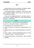
外形图
1642EM设备
2010年8月28日
阿尔卡特北京分公司
1
1642EM功能介绍
1、1642EM是上海贝尔阿尔卡特的光多业务产品系列OMSN中的 一员,作为一款采用紧凑型结构设计的产品,1642EM适用于城 域网络的接入层和用户侧,可向用户侧设备提供以太网、SDH和 其它数据业务的传送。 2、1642 EM的核心是一块紧凑型ADM板卡,即MB板。该板卡集 成了2个STM-1/4线路接口和交叉矩阵,该ADM板卡还具备时钟 功能,设备控制功能。设备上总共提供7个槽位:最下面是主控 盘,提供STM-1/4的ADM,主控盘槽位上方是4个业务槽位,设 备的左侧和右侧分别为风扇盘和电源接入盘,可用于大型企业网络 接入城域网。 3、1642EM的交叉连接矩阵为所有配置提供VC12,VC3或VC4级 别的全交叉。同时,支持模块化的STM-1或STM-4的接口设计, 光接口可以灵活的组合(任何短距或长距的光口),主要接口如 下:
- 1、下载文档前请自行甄别文档内容的完整性,平台不提供额外的编辑、内容补充、找答案等附加服务。
- 2、"仅部分预览"的文档,不可在线预览部分如存在完整性等问题,可反馈申请退款(可完整预览的文档不适用该条件!)。
- 3、如文档侵犯您的权益,请联系客服反馈,我们会尽快为您处理(人工客服工作时间:9:00-18:30)。
4,0 V
SEL>> 0V 4,0 V
V (video)
0V 0 V (AV) 1,0 2,0 Time s 3,0 4,0
IEC 1913/02
NOTE The response shown is caused by an intermittent narrowband signal with a duration of 0,3 s and a repetition frequency of 1 Hz, when a time constant of 100 ms is used. If the time constant is 160 ms, the peaks at the output of the meter simulating network will be lower.
IEC 2002 Droits de reproduction réservés Copyright - all rights reserved
International Electrotechnical Commission, 3, rue de Varembé, PO Box 131, CH-1211 Geneva 20, Switzerland Telephone: +41 22 919 02 11 Telefax: +41 22 919 03 00 E-mail: inmail@iec.ch Web: www.iec.ch
X.1
X.1.1
Description
Introduction of the monopole (1 m rod) antenna system
Monopole (rod) antennas are typically used at frequencies below 30 MHz but are sometimes used at higher frequencies. Because of the long wavelength associated with the low frequency range, methods used to calibrate or characterize antennas at higher frequencies are not applicable. The techniques defined in this annex are applicable for frequencies up to 30 MHz. Using due care, this method has been used commercially with small (less than 1 dB) error. The primary method for traceability of antenna factor to national standards is to illuminate the whole antenna by a plane wave. An alternative method, capacitor substitution of the monopole element, is contained in this annex. Although it is possible to determine the antenna factor by the capacitor substitution method, it requires expert knowledge to achieve the true antenna factor to within ±1 dB during the actual calibration process. This is especially the case when designing jigs for types of antenna whose monopole element is not attachable by a coaxial connector. Finally, care in the use of the capacitor substitution method is required especially at frequencies above 10 MHz and for active antennas. X.1.2 Monopole (rod) antenna performance equations
FDIS CISPR/A/374/FDIS Report on voting CISPR/A/395/RVD
Full information on the voting for the approval of this amendment can be found in the report on voting indicated in the above table. The committee has decided that the contents of the base publication and its amendments will remain unchanged until 2003. At this date, the publication will be • • • • reconfirmed; withdrawn; replaced by a revised edition, or amended. __________ Page 5 CONTENTS Add, before the figures, the title of the new Annex X as follows: Annex X (normative) Monopole (1 m rod antenna) performance equations and characterization of the associated antenna matching network Amend, at the end of the contents, the list of figures as follows: Figures 1 to X.3
COMMISSION ÉLECTROTECHNIQUE INTERNATIONALE INTERNATIONAL ELECTRO1
1999
AMENDEMENT 1 AMENDMENT 1 2002-08
COMITÉ INTERNATIONAL SPÉCIAL DES PERTURBATIONS RADIOÉLECTRIQUES INTERNATIONAL SPECIAL COMMITTEE ON RADIO INTERFERENCE
Pour prix, voir catalogue en vigueur For price, see current catalogue
CISPR 16-1 Amend.1 © IEC:2002
–3–
FOREWORD
This amendment has been prepared by CISPR subcommittee A: Radio-interference measurements and statistical methods. The text of this amendment is based on the following documents:
Repeated rectangular pulses for modulation Duration = T M Period = 1,6 s Band A/B receiver T M = 0,16 s 0,353 ( = –9,0 dB) Band C/D receiver T M = 0,1 s 0,353 ( = –9,0 dB)
The response to intermittent, unsteady and drifting narrowband disturbances shall be such that the measurement result is equivalent to the peak reading of a meter with a time constant of 160 ms for bands A and B and of 100 ms for bands C and D, as depicted in Figure 61. The time constant is as defined in A.3.1. This can be accomplished by a meter simulating network following the envelope detector of the receiver. The peak reading may be taken, for example, by continuous monitoring of the meter output using an A/D converter and a microprocessor, as shown in Figure 60.
Page 407 Add the following new annex:
Annex X (normative) Monopole (1 m rod antenna) performance equations and characterization of the associated antenna matching network 1
Amendement 1 Spécifications des méthodes et des appareils de mesure des perturbations radioélectriques et de l'immunité aux perturbations radioélectriques – Partie 1: Appareils de mesure des perturbations radioélectriques et de l'immunité aux perturbations radioélectriques Amendment 1 Specification for radio disturbance and immunity measuring apparatus and methods – Part 1: Radio disturbance and immunity measuring apparatus