ABB MNS Service Manual_CN
ABB MOTION SERVICES ACW600到ACS880LC的转型服务说明书

Minimize planned downtimeDelivered in pre-assemblies to be assembled on siteRapid deploymentReduced waste and investment—A B B MOTI O N S ERV I CE SACW600 to ACS880LC retrofitExtending life cycle. Enhancing performance.ABB Retrofit service is a fast and efficient way to modernize your ACW600 drive and to bringreliability improvements to your plant and process. The Retrofit service can be done in challenging environments and carried out in line with your own productionschedules to minimize unexpected downtime and avoid additional maintenance breaks.Fast and efficient way to modernize your drives ACW600 drives are coming to the end of their life cycle and it will become difficult, if not impossible, to maintain them with normal maintenance programs. ABB enables you to continue to extract value from your asset with retrofit solutions that will update the drive to new ACS880 technology with the latest features and change its life cycle phase back to Active, ensuring the full spare part and technicalsupport is available after the retrofit.The benefits of ACW600 to ACS880LC retrofitsEnsure customer support for your equipmentRobust ACW600 drives are reaching the end of their life cycle, which means that support and spare part availability cannot be guaranteed in the near future. Retrofitting your drive with new ACS880 technology with the latest features changes the life cycle phase of the drive back to Active and ensures that full spare part and technical support will be available.Perform modernization in places, where it is difficult to accessRetrofit is built on-site, so there is no need for docking/cutting holes in the construction. The existing motor and grid connection is used, which means that there is no need for structural work. The retrofit will be delivered in parts that can be transported through a narrow access. There is no need to make changes in the surrounding constructions.Minimize the downtimeKeep the ship operating at sea during themodernization action. The retrofit can be done one drive at a time, so the ship can operate during the upgrade. If redundant drives are used, the redundancy allows operation with reduced capacity.Modernization can be done during operation,causing minimum production losses.ABB Retrofit service in a nutshell What will change after the retrofit?The ABB Retrofit service is a fast, effective way to modernize installed drives,bringing immediate performance improvements to a plant or process.The retrofit is designed so that the drive units can be replaced with new ACS880inverter modules using the installation hardware and instructions included in the delivery. The existing infrastructure, cabinets and cabling, electrical machinery and automation system do not need to be replaced.Delivery in small sub-assemblies to enable installation in places with limited accessNo change to incoming cablesCompatible ACS880supply units modules with internal AC chokes—Supply ACW631/ACW633 to ACS880R-307LCS6INU ACW610 to ACS880R-107LCS6—LCU ACW695 to ACS880R-1007LCS6 New ACS880 technology with a possibility for digital connectivity MarinecompatibledesignNo change to the motor connection– old motor cablescan be usedInternal watercircuit renewedto increase robustnessLiquid inlet/remains in the original placeTechnical dataSelection table for upgrade and retrofit types —Retrofit types for ABB ACW600 drives*) Includes 400 mm cabling section**) Includes 600 mm cabling section4F P S 10001452777 R E V B E N 24.5.2022—We reserve the right to make technical changes or modify the contents of this document without prior notice. With regard to purchase orders, the agreed particulars shall prevail. ABB does not accept any responsibility whatsoever for potential errors or possible lack of information in this document.We reserve all rights in this document and in the subject matter and illustrations contained therein.Any reproduction, disclosure to third parties or utilization of its contents – in whole or in parts – is forbidden without prior written consent of ABB. Copyright© 2022 ABB. All rights reserved.—For more information, please contact your local ABB representative or visit/service/motion /service/motion/modernization-and-performance-improvement-services/drives /drives/channel-partners/search—Service delivery processCheck the drive typeACW600 drives are at the end of their Classic life cycle phase; now is the time to consider a retrofit service.Assess the existing system with ABBAssessing the existing installation allows ABB specialists to identify all required elements in order to determine retrofit options as well as to schedule and plan the installation.Configure the solution with ABBThe retrofit service is configured to match the current system demands,often without updating external components. In case the configured solution doesn’t match your requirements, ABB can also provide engineering to fulfill specific demands.Scheduling the installationRetrofit is convenient and easy to integrate into your maintenance schedules. It can be carried out by minimizing the need for production stoppage.Installation and commissioning with ABBThe retrofit service is designed to save installation time. ABB-certified service engineers install and commission the retrofit.Continue efficient operationThe drive system is restored to the active life cycle phase with full support, including spare parts and technical advice. The retrofit is supplied with atwo-year warranty.。
ABB机器人维护手册

ABB机器⼈维护⼿册ABB机器⼈维护⼿册0.0.1 前⾔本⼿册包含了关于机械和电⽓上的维护及维修说明在维护及维修机器⼈前,请阅读本⼿册本⼿册适⽤于:* ⽤户⾃⼰的维修⼈员* 其它维修⼈员阅读者需要:* 是有⼀定技能的维修⼈员* 有机械维修⽅⾯的知识* 有电⽓维修⽅⾯的知识第⼀章:安全、维护有危险的安全1.2.1 钳⼦的安全确定钳⼦可以阻⽌⼯作件的下落1.2.2 ⼯具/⼯作件的安全见⽤户安全指南1.2.3 ⽓动/液压系统的安全见⽤户安全指南1.2.4 操作中的⼀些危险见⽤户安全指南1.2.5 安装及维护过程中的危险见⽤户安全指南1.2.6 电⽓元件的危险见⽤户安全指南1.3.4 刹车检查正常运⾏前,需检查电机刹车每个轴的电机刹车检查⽅法如下:1、运⾏每个机械⼿的轴到它负载最⼤的位置2、将机器⼈控制器上的电机模式选择开关打到电机关(MOTORSOFF)的位置3、检查轴是否在其原来的位置如果电机关掉后,机械⼿仍保持其位置,说明刹车良好。
1.3.5 失去减速运⾏(250mm/s)功能的危险不要从电脑或者⽰教器上改变齿轮变速⽐或其它运动参数。
这将影响减速运⾏(250mm/s)功能。
1.3.6 安全使⽤⽰教器安装在⽰教器上的使能设备按钮(Enabling device),当按下⼀半时,系统变为电机开(MOTORS ON)模式。
当松开或全部按下按钮时,系统变为电机关(MOTORSOFF)模式。
为了安全使⽤⽰教器,必须遵循以下原则使能设备按钮(Enabling device)不能失去功能编程或调试的时候,当机器⼈不需要移动时,⽴即松开使能设备按钮(Enabling device)。
当编程⼈员进⼊安全区域后,必须随时将⽰教器带在⾝上,避免其他⼈移动机器⼈。
1.3.7 在机械⼿的⼯作范围内⼯作如果必须在机械⼿⼯作范围内⼯作,需遵守以下⼏点:-控制器上的模式选择开关必须打到⼿动位置,以便操作使能设备来断开电脑或遥控操作-当模式选择开关在<250mm/s位置时候,最⼤速度限制在250mm/s .进⼊⼯作区,开关⼀般都打到这个位置.只有对机器⼈⼗分了解的⼈才可以使⽤全速(100%full speed)-注意机械⼿的旋转轴,当⼼头发或⾐服搅到上⾯.另外注意机械⼿上其它选择部件或其它设备-检查每个轴的电机刹车(见1.3.4)第⼆章、相关信息2.0.1 本章介绍了⼀些普通元件信息,特殊信息将在以后提到2.1.2 旋转关节本节描述如何上紧机械⼿或控制器上的旋转接头这些旋转部位的说明和扭矩值只适⽤于⾦属部件,不适⽤于软的易碎的材料该说明只适⽤于标准的旋转接头UNBRAKO UNBRAKO是⼀种由ABB推荐的特殊的螺钉,表⾯经过特殊处理,很耐⽤在⽤到这种螺钉的地⽅会有说明,并且不能⽤其它螺钉替代.⽤其它螺钉将不会保证不发⽣事故.Gleitmo Gleitmo是⼀种表⾯处理⽅法,经过这种处理后,在拧紧螺栓的时候会减⼩表⾯的摩擦.这种螺栓可以重复使⽤3-4次,当表⾯的覆盖层消失后,必须更换新的当拧动这种螺栓时,需戴上橡胶⼿套润滑螺栓的润滑⽤Molycote 1000(或其它润滑油),这在维修或安装⼿册中有说明按以下步骤操作:1、加润滑油在螺栓的螺纹上2、加润滑油在螺栓的平垫和螺帽上3、M8以上的螺栓,必须⽤扳⼿上紧润滑编号Molycote 1000 1171 2016-618以下的表格描述不同螺栓的扭矩值平⼝及⼗字型螺栓六⾓套筒型螺栓六⾓套筒型并带润滑的螺栓2.1.5 标准⼯具 IRB6600/6650/7600以下包含了⼀些标准⼯具说明 IRB66X0(数量) 序列号⽌脱螺栓(M16X60) 2 3HAB 3409-86 校准笔 1 3HAC 15716-1 降下臂的⼯具 1 3HAC 13659-1 齿轮箱曲柄 1 3HAC 16488-1定位销M12X150 2 3HAC 13056-2定位销M12X200 2 3HAC 13056-3定位销M12X250 1 3HAC 13056-4定位销M8X100 2 3HAC 15520-1定位销M8X150 2 3HAC 15520-2定位销M10X100 2 3HAC 15521-1定位销M10X150 2 3HAC 15521-2定位销M16X300 2 3HAC 13120-5定位销连接ax2,3,100mm 1 3HAC 14628-2定位销连接ax2,3,80mm 1 3HAC 14628-1 液压滚筒 1 3HAC 11731-1 特殊⼯具说明 IRB66X0(数量)序列号液压泵80Mpa 1 3HAC 13086-1 起重设备,基座 1 3HAC 15560-1 起重设备,机器⼈ 1 3HAC 15607-1 起重设备,上臂 13HAC 15994-1 吊物孔VLBG M12 1 3HAC 16131-1吊物孔M12 2 3HAC 14457-3 吊物孔M16 2 3HAC 14457-4 起重⼯具(链条) 1 3HAC 15556-1 起重⼯具,变速箱ax2 1 3HAC 13698-1 起重⼯具,电机ax1,4,5 1 3HAC 14459-1 起重⼯具,电机ax2,3,4 1 3HAV 15534-1⽌脱螺栓ax 3 2 3HAC 12708-1压⼒⼯具ax 2 轴承 1 3HAC 13527-1压⼒⼯具ac 2 轴 1 3HAC 13452-1压⼒⼯具,平衡设备轴 1 3HAC 17129-1压⼒⼯具,平衡设备 1 3HAC 15767-1拉⼒⼯具,平衡设备轴 1 3HAC 12475-1移动⼯具,电机M10x 2 3HAC 14972-1移动⼯具,电机M12x 2 3HAC 14631-1移动⼯具,电机M12x 2 3HAC 14973-1旋转⼯具 1 3HAC 17105-1底座 1 3HAC 15535-1调平⼯具 1 3HAC 15943-2机械停⽌轴3的垫圈 2 3HAA 1001-1862.1.6 检漏测试当更换或修理电机或变速箱后,必须对变速箱内的油作个检查,这就是检漏测试所需设备为专门的检查装置,序列号为3HAC 0207-1⽅法及步骤步骤⽅法说明1按要求完成电机或齿轮的更换2 打开齿轮箱顶端的油盖,然后将测漏装置放在上⾯.可能还需要⼯具包⾥的测漏装置的调节器3 使⽤压缩空⽓,然后提⾼压⼒到推荐值:⼀个特定值 (20-25KPa)4 断开压⼒空⽓连接5 等待8-10分钟.(检查是否有压⼒如果压缩空⽓的温度与齿轮周损失) 围的油的温度相差太⼤,或许有轻微的压⼒增减,这是正常的6 看压⼒是否下降明显7 ⽤测漏喷嘴对怀疑有泄漏的地⽅喷射,起泡则说明有泄漏8 发现有泄漏,请采取必要的措施改正2.1.7 起重设备不同的修理及维护⼯作需要不同的起重设备,这在维修指南中有指明,但怎样使⽤在维修指南中没有说明,所以⼀定要保留这些⼯具的使⽤说明书第三章、维护信息系统(SIS)3.0.1 使⽤SIS系统这是⼀个简短的维护信息系统(SIS)的使⽤说明,详细的资料可在以下⼏处找到: * 维护信息系统,SIS* 定义SIS输⼊参数* 设置SIS参数* SIS参数的交换* 读出SIS的输出⽇志基本⽅法及步骤3.0.2 维护信息系统(SIS)维护信息系统(SIS)是⼀个在机器⼈控制器⾥的软件功能,其简单化了机器⼈系统的维护.其管理⼯作时间及模式,并在预定的维护时间到后为提醒操作⼈员管理功能计数器可以设为:* ⽇历时间计数,基于⽇历时间的报警* ⼯作时间计数,基于⼯作时间的报警* 变速箱1的⼯作时间计数,基于变速箱1的维护周的百分⽐报警* 变速箱2的⼯作时间计数,基于变速箱2的维护周的百分⽐报警* 变速箱3的⼯作时间计数,基于变速箱3的维护周的百分⽐报警* 变速箱6的⼯作时间计数,基于变速箱6的维护周的百分⽐报警下图显⽰了⼏种不同的选择“OK”表⽰计数器⾥⾯没有维护时限到,如果有维护时间到,计数器的名字为变为”NOK”⽇历时间(Calendar Time)这是⼀个内部控制系统的时间,基于这个时间,可以设定维护周期Prev service 计数器上⼀次被复位的⽇期,也就是上次维护的⽇期.如何输⼊在设定SIS参数(Setting the SISparameters)中有说明Elapsed time 从上次复位到现在的时间Next service 计划中下次维护的时间. 如何输⼊在设定SIS参数(Setting the SIS parameters)中有说明Remaining time 到下次维护所剩的时间⼯作时间(Operation time)这是⼀个内部控制系统的时间,当电机开(MOTORS ON)信号激活时开始计数.也就是机器⼈⼯作的时间.Service interval 指定的维护周期. 如何输⼊在设定SIS参数(Setting the SIS parameters)中有说明Elapsed time 从上次复位到现在的时间Remaining time 到下次维护以前,剩余的⼯作时间变速箱(Gearbox)基于度量单位,如扭矩(Torque)和转速(RPM),系统计算⼀个预期的维护周期,需要维护时,在⽰教器上会有显⽰,如何存取会在读出SIS的输出⽇志(Reading the SIS output logs)中说明Axis x OK 维护状态,也就是说⾃动计算出来的时间还没到Axis x NOK 维护周期到Axis x N/A ⽆可⽤的维护周期参数,⽤于轴4和5上图显⽰了轴1的例⼦,其它轴也如此Consumed time 消耗的时间,占总时间的百分⽐Elapsed time 从上次复位到现在的时间Remaining time 到下次维护以前,剩余的⼯作时间复位 Reset Values 所有的计数器都可以随时复位⼀旦复位,变量都sisRestartDate和sisCalendarT复位,如上图参数的说明,见参数输出(Exporting the SIS date) Yes将计数器复位到0No不复位,并回到上级菜单复位后,运⾏时间也被复位,如上图Yes将计数器复位到0No不复位,并回到上级菜单复位后,变量sisL10h_x和sisL10h_Time也被复位Yes将计数器复位到0No不复位,并回到上级菜单达到维护周期当超过维护周期的间隔时间后,⼀条信息(ServiceService Interval exceeded Interval exceeded!)会显⽰在计数器的参数下⽅这个窗⼝可以在任何⼀个模式下显⽰,⽇历时间(calendar time)、运⾏时间(operation time)、变速箱时间(gearbox time)另外,⼀条错误信息也会显⽰在⽰教器上⽆可⽤的参数对于所选的模式⽆可⽤参数,在窗⼝下⽅会有⼀条No date available 信息(No date available!)显⽰这个窗⼝可以在任何⼀个模式下显⽰,⽇历时间(calendar time)、运⾏时间(operation time)、变速箱时间(gearbox time)退出ExitYes 退出维护信息系统No 回到维护信息系统3.0.3 定义SIS输⼊参数本节详细描述了可以被设定的各种参数.这些参数可以由对机器⼈的⼯作环境⾮常熟悉的⼈来设定.由于计数器是由⽤户⾃定义,所以ABB不能提供任何推荐值下图显⽰了被选参数的选项运⾏时间限制(维护标准)Operation time limit(service level)选择维护周期的运⾏⼩时数,例如,设定值为”20,000”,SIS将会这个时间标准来启动报警,运⾏时间报警(Operatiom time warning)上⾯定义的运⾏时间限制(Operation time limit)的百分⽐,例如:设定值为”90”,SIS将会在上次复位后18,000⼩时过后报警⽇历时间限制(维护标准)Calendar time limit(service level)选择维护周期的年数,例如:设定值为”2”,SIS系统会以这个时间作为报警标准⽇历时间报警(Calendar time warning)上⾯所设定的⽇历时间(Calendar time limit)的百分⽐,例如:设定值为”90”,系统将在上次复位后两年的90%也就是657天后报警变速箱报警(Gearbox warning)系统计算的变速箱维护周期的百分⽐,例如,设定值为”90”,系统将会在超过预期的每个齿轮的维护时间的90%的时候报警机器⼈⾃动检测并收集所需要的变量来计算每个齿轮的维护周期这是⼀个从早期的运⾏中收集来的推断值,所收集的参数包括:。
ABB 网络保护与控制产品说明书

-Conceptional overview diagrams -Necessary overview panels -Layout of mimic panels
-Specification and adressing of signals -MMI pictures of switchgear components
-Logic diagrams
-Documentation
on system configuration and
settings -Different connecting diagrams
If requested, the drawings Iisted above are submitted to the customer for review and approval.
ABB Relays is able to render assistance and
recommendations during the preparation of concepts and specifications for protection and controi systems. ABB Relays can also assist the customer with network studies and calculations.
ABB Network Controi & Protection
.
1MDBOOOO3-EN
Page 1 March 1992 Changed since August 1990 Data subject to change without
natice
Relays Systems
~Ab' röäffrängeö{protectivereläYSforgenera- ~cluded in this Buyer's Guide and can easily
ABB机器人操作员手册 - 紧急安全信息

操作员手册紧急安全信息IRC5文档编号:3HAC027098-001修订:L ©版权所有2007-2015ABB。
保留所有权利。
本手册中包含的信息如有变更,恕不另行通知,且不应视为ABB的承诺。
ABB对本手册中可能出现的错误概不负责。
除本手册中有明确陈述之外,本手册中的任何内容不应解释为ABB对个人损失、财产损坏或具体适用性等做出的任何担保或保证。
ABB对因使用本手册及其中所述产品而引起的意外或间接伤害概不负责。
未经ABB的书面许可,不得再生或复制本手册和其中的任何部件。
可从ABB处获取此手册的额外复印件。
本出版物的原始语言为英语。
所有其他语言版本均翻译自英语版本。
©版权所有2007-2015ABB。
保留所有权利。
ABB ABRobotics ProductsSe-72168Västerås瑞典目表目表手册概述.............................................................................................................................................7 1紧急安全信息991.1停止系统..........................................................................................................121.2灭火................................................................................................................131.3关闭控制器的所有电源........................................................................................151.4解救受困于机器人手臂的工作人员..........................................................................1.5紧急释放机器人手臂...........................................................................................16251.6从紧急停止状态恢复...........................................................................................27索引3HAC027098-001修订:L5 3HAC027098-001-010修订:L©版权所有2007-2015ABB。
ABB 产品信息说明书
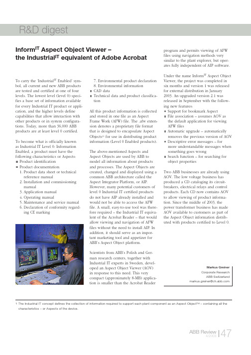
To carry the ‘Industrial IT Enabled’ sym-bol, all current and new ABB products are tested and certified at one of four levels. The lowest level (level 0) speci-fies a base set of information available for every Industrial IT product or appli-cation, and the higher levels define capabilities that allow interaction with other products or in system configura-tions. Today, more than 36,000 ABB products are at least level 0 certified. To become what is officially known as Industrial IT Level 0: Information Enabled, a product must have the following characteristics or Aspects: Product identificationProduct documentation:1.Product data sheet or technicalreference manual2.Installation and commissioningmanual3.Application manual4.Operating manual5.Maintenance and service manual6.Declaration of conformity regard-ing CE marking7.Environmental product declaration8.Environmental informationCAD dataTechnical data and product classifica-tionAll this product information is collectedand stored in one file as an AspectFrame Work (AFW) file. The .afw exten-sion denotes a proprietary file formatthat is designed to encapsulate AspectObjects1)for use in distributing productinformation (Level 0 Enabled products).The above-mentioned Aspects andAspect Objects are used by ABB tomodel all information about productsand processes. The Aspect Objects arecreated, changed and displayed using acommon ABB architecture called theAspect Integrator Platform, or AIP.However, many potential customers oflevel 0 Industrial IT certified productsdo not have AIP already installed andwould not be able to access the AFWfile. A small, easy-to-use tool was there-fore required – the Industrial IT equiva-lent of the Acrobat Reader – that wouldallow viewing and navigation of AFWfiles without the need to install AIP. Inaddition, it should serve as an impor-tant marketing tool and appetizer forABB’s Aspect Object platform.Scientists from ABB’s Polish and Ger-man research centers, together withIndustrial IT experts in Sweden, devel-oped an Aspect Object Viewer (AOV)in response to this need. This verycompact (approximately 8-MB) applica-tion is smaller than the Acrobat Readerprogram and permits viewing of AFWfiles using navigation methods verysimilar to the plant explorer, but oper-ates fully independent of AIP software.Under the name Inform IT Aspect ObjectViewer, the project was completed insix months and version 1 was releasedfor external distribution in January2003. An upgraded version 2.1 wasreleased in September with the follow-ing new features:Support for bookmark AspectFile association – assumes AOV asthe default application for viewingAFW filesAutomatic upgrade – automaticallyremoves the previous version of AOVDescriptive error messages – formore understandable messages whensomething goes wrongSearch function – for searching forobject propertiesTwo ABB businesses are already usingAOV. The low voltage business hasproduced a CD cataloging its circuit-breakers, electrical relays and controlproducts. Each CD now contains AOVto allow viewing of product informa-tion. Since the middle of 2003, thepower transformer business has madeAOV available to customers as part ofthe Aspect Object information distrib-uted with products certified to Level 0.Inform IT Aspect Object Viewer –the Industrial ITequivalent of Adobe AcrobatMarkus GreinerCorporate ResearchABB Switzerland*********************.com 1)The Industrial IT concept defines the collection of information required to support each plant component as an Aspect Object TM– containing all the characteristics – or Aspects of the device.An ABB collaboration has resulted in an improved programming method that not only speeds up the programming of robot automation tasks, but also opens up areas for automation that are presently inaccessible due to traditional programming being too complex and taking too long in relation to production time.ABB robots have to be extremely versa-tile. Used across almost the whole of in-dustry for tasks ranging from automated assembly and materials handling to arc-welding, every extra ounce of versatility added to them can significantly increase their range of application. As a robot is essentially a moving object, spatial in-formation has to be conveyed accurately and reliably to it. Adding flexibility therefore makes traditional program-ming more complex and time-consum-ing. The advantages to be gained fromfinding new, alternative methods of re-laying information fast (and accurately)to the robot make this field of researchas challenging as it is interesting.With robots playing an ever more im-portant role in our everyday lives, theidea that humans should be able tocommunicate with them using methodsas close as possible to those they use tocommunicate with each other is gainingmomentum. Communication amonghumans is multi-modal (ie, a combina-tion of gesture and speech) and oftenintuitive, and institutions like CarnegieMellon University (CMU) have used thisidea to increase human-machine inter-action. As a world leader in industrialrobot technology, ABB is benefitingfrom this experience by working to-gether with the Advanced MechatronicsLaboratory at CMU on a project whichuses the idea of the human arm andhand gestures as a natural way toconvey spatial information – in otherwords, gesture-based programming.ABB’s approach is backed up by Pro-fessor Pradeep Khosla, head of the AMLand Electrical and Computer Engineer-ing Department at CMU when he says,“As robots enter the human environ-ment and come into contact with inex-perienced users, they need to be ableto interact with the users in an intuitiveway. The keyboard and mouse are nolonger acceptable as the only meansof input.”Gesture-based programmingin a nutshellCMU has been working in the area ofgesture-based programming (GBP) formany years now. The goal of GBP is toprovide a more natural environmentfor the user, and to generate morecomplete and successful programs byfocusing on task experts rather thanprogramming experts.The process begins with a persondemonstrating the task to be pro-grammed. The person’s hand and fin-gertips are observed through a sen-sorized glove with special tactilefingertips. The modular glove systemsenses hand pose, finger joint anglesand fingertip contact conditions.Objects in the environment are sensedwith computer vision while a speechrecognition system extracts high-levelcontrol information. Primitive gestureclasses are extracted from the raw sen-sor information and passed to a gestureinterpretation network. The system isself-adaptive in the sense that knowl-edge of previously acquired skillsretained by the system is used to inter-pret the gestures during training, withcontrol feedback provided during run-time. The output of the GBP system isthe executable program for performingThe ‘human touch’ –advanced robot programmingR&D digest the demonstrated task on the targethardware.What it means for ABBSince robotic arc welding is inherentlythree-dimensional, hand gestureswould be an intuitive tool for provid-ing parameters such as position, veloci-ty, acceleration, size, direction, angleand angular velocity to enable fasterand accurate programming of the ro-bot. Speech would also play an impor-tant part in enhancing this system byproviding high-level control informa-tion. Therefore, CMU scientists togetherwith ABB experts have developed andevaluated a programming system witha multi-modal interface for robotic andarc-welding applications.The system has the following main com-ponents:Cyberglove to measure the positionand movement of the fingers andwrist (gesture sensing)Polhemus Fastrak 6-DOF sensors for position sensingMicrosoft speech recognition system PCWebWare for robot-PC communications ABB robotThe PC mediates between the multi-modal input devices (glove and speech) and the ABB robot. On the input side it runs software that translates raw voice and glove inputs into robot controller commands. On the output side it sends commands to the robot that contain cor-rect position and orientation information based on the appropriate coordinate transformations.The robot is programmed in three modes: absolute, jogging and slave. In absolute mode, ‘waypoints’ are pro-grammed by pointing to and storing various positions in space with the in-dex finger. However, due to the limited accuracy of the positioning system (+/– 5 cm), the stored positions have to be adjusted to meet the required accu-racy (< 1mm) for arc-welding. Theseadjustments can be performed by either‘jogging’ or ‘slaving’. Jogging, as it isused in robotics, means controlling theend effector (a device or tool connect-ed to the end of the robot arm) directlyusing either a joystick or push buttons.In this case the joystick and pushbut-tons are replaced by gestures and voicecommands. For example, the ‘jog’ com-mand makes the robot move a certaindistance in the direction of the indexfinger. In slave mode, the robot mimicsthe motion of the hand using an ad-justable scaling factor. This means thatif the human hand moves a distance of1 cm, the robot responds by moving1 mm (depending on the scale settings)and so on until the desired accuracyhas been reachedThe system has been tested and evaluat-ed in a real arc-welding environmentusing ABB’s IRB140 and IRB1400 robots.The programming system has so farproved capable of producing the neces-sary accuracy, allowing high-qualitywelds to be produced. In addition, ob-servations from the evaluation indicatethat it is a very easy method to learnand master.The joint collaboration between engi-neers at CMU and ABB experts has, inaddition to generating valuable results,built up extensive know-how which willbe used within ABB for further researchin the field of robot programming.Dr. John DolanThe Robotics InstituteCarnegie Mellon University**********.eduMartin StrandAdvanced Industrial Communication GroupABB Corporate ResearchVästerås/Sweden********************.comR&D digestA simulation system that makes use of state-of-the-art web technology is used to train Novolen ®gas-phase polypropy-lene process plant operators on a rigor-ous dynamic plant model via Internet,Intranet, or as a stand-alone system.Simulation-based education is themethod preferred by many companies today for providing ‘on the job’ training.As computational capabilities become ever faster and improved tools appear on the market, computer-based educa-tional services, particularly in the chemi-cal process industries, are expanding.These services can mimic true plant operation through computer simulation,thus providing a safe and efficientmethod of training plant operators and other production personnel. In addition,operators may be trained to handle normal and abnormal plant operating conditions without endangering the actual plant [1].ABB Corporate Research has developed a simulation-based process-learning tool for polypropylene plants. Together with Novolen Technology Holdings C.V.(NTH), a joint venture of ABB LummusGlobal and Equistar, ABB has developed a learning tool aimed at the Novolen process owned by NTH. Called Novolen Operator Training Simulation (Novolen OTS), the tool’s strengths lie in its unique model, the robustness of the software and simulator, and its ease of maintenance and extendability. Because plants using the Novolen process are located around the world, using a web-enabled tool is particularly appropriate.Novolen OTS based training is possible over the Internet, Intranet, or on a stand-alone computer.The targeted users are Novolen process plant operators, operator trainers, and process engineers. A major training ob-jective is that the operators learn the dy-namic characteristics of the plant during standard operation and in abnormal sit-uations, including process disturbances,start-up/shutdown of the plant, and transitions between different product grades. Moreover, they obtain an under-standing of the relationship between operating conditions and resulting prod-uct quality. This permits operators to improve their ability to operate plants and to diagnose problems.The Novolen process plantIn the Novolen ®process, polymerization is conducted in one or two gas-phase reactors. Only two reactors connected in series are needed to produce a wide range of products, including super-high impact copolymers. In addition to the reactors, components in the plant in-clude condensers, degassing vessels,product silos, an extruder, controllers,and emergency valves .OTS component overviewThe main components of the Novolen ®OTS system include:1 A simulator, which includes a model of the process, the control system and the safety interlocksA generic operator station as a human system interfaceA software framework, which inte-grates these main components and provides for simulation services over the Internet.The graphical user interface (GUI) is a generic representation of an operator station . As the Novolen ® OTS is used in self-paced mode, no instructor station is required. A standard web browser,such as Internet Explorer, represents the GUI, displaying simulation results aswell as allowing user input.The components in the user interface,such as valves, numeric text boxes,buttons, level indicators, and flares,reflect the current status of the simula-tion. When necessary, the components are used to change the course of the simulation. For instance, valves areclosed/opened by clicking on them, and specific numbers are entered using the numeric text boxes. The condensers,degassing vessels, product silos, extrud-er, controllers, and emergency valves are all represented in the tool.Besides the above-mentioned basic functionality, additional functions are implemented for an enhanced learning experience. For example, the speed of the simulation can be increased in order to use the tool more efficiently,or a snapshot of the current state can be taken and reused in later training sessions.A normal training session starts by navi-gating to the web site of the server.After a login procedure in which access rights are checked, a simulation is start-ed with one of several pre-configured scenarios. The trainee may then change the course of the simulation by chang-ing process parameters, such as flow rates or temperature set-points. These2A new web-based simulation tool for polymer plant operatorsR&D digestchanges result in a dynamic response,which the trainee observes and reacts to accordingly. Stopping the simulation and closing the web browser terminate the session.The Novolen ®OTS can be fully installed and run on a standard off-the-shelf PC.Alternatively, it can be run over theInter/intranet so that only a web browser is needed on the user’s side.TechnologyThe dynamic model is a first-principle based model of the Novolen ®process with major unit operations [2]. It is com-posed of ordinary differential equations and has about 100 states. A wide range of operating conditions was required because the process tool was designed in answer to a major training objective:to focus on the dynamic characteristics of the plant during standard operation (eg, transition between different poly-mer grades) and abnormal situations (eg, a blocked pipe).The model is parameterized to easily permit adjustments that reflect different plant sizes and configurations. Special attention has been given to the integrity of the numerical solution to avoid simu-lation crashes during training.The tool uses a client-server architecture where the simulation services are server based. The GUI is presented on the client’s computer. The interaction be-tween the client and the server takes place via HTTP, the most common com-munication protocol on the Internet.The screens within the tool are built as HTML pages with Java applets repre-senting the data. The HTML-based ap-proach makes it possible to flexibly link to other information sources, and enables integration with other e-learning systems. The use of Java makes it possi-ble to program a variety of specialized components, allowing the user to influ-ence the data in various ways. Despite this, all major browsers with Java capa-bilities can be used for server access.On the server side, a web server frame-work (consisting of a multi-layer archi-tecture) provides the functionalityneeded for dynamic data to flow to and from the web pages. Innermost is an OPC server, which encapsulates the model and provides a standard inter-face to its data. The web server creates an HTTP-based service where data can stream from the OPC to Java servlets.These servlets are connected via HTTP to the Java applets ‘living’ on the client side. ABB developed the internal OPC connectivity by using the Java Native Interface to bridge the gap between Windows 32 applications and Java [3].Value extensionWith Novolen ®OTS, NTH has extended the value proposition of its current tech-nology offering with the creation of a highly robust and extendable tool using standard software and modeling tech-nologies. This tool will enable current and future licensees of the Novolen process to improve the understanding and operation of their plants. Licensees will be able to choose between web-based or stand-alone training sessions.Initial feedback from users has been so positive that many feel such a tool will eventually become essential for any company in the chemical process indus-tries.Reference[1]A. Kroll: Trainingssimulation für die Prozessindustrien: Status, Trends und Ausblick. Teil 1+2. Automatisierungstechnische Praxis atp (2003) 45, no. 2, pp 50–57, and no. 3, pp 55–60.[2]C.-U. Schmidt, R. Böttcher: 2000. ProveT – Training simulator for Novolen Process. 1st European Conf on the Reaction Engineering of Polyolefins, 2000,Lyons, 114–116.[3]R. Nyström, et al: 2003. Web-based training for polymer plant operators using process simulation. Automatisierungstechnik 51, no. 11.Dr. Rasmus NyströmDr. Andreas Kroll Dr. Alexander FrickChristian StichABB Corporate Research CenterLadenburg, GermanyKlaus HüttenDr. Franz Langhauser Dr. Wilhelm Seebass Dr. Meinolf Kersting ABB Lummus GlobalNovolen Technology Division。
ABB机器人实用手册

一、系统安全以下的安全守则必须遵守,因为机器人系统复杂而且危险性大,*万一发生火灾,请使用二氧化炭灭火器。
-急停开关(E-Stop )不允许被短接。
-机器人处于自动模式时,不允许进入其运动所及的区域。
-在任何情况下,不要使用原始盘,用复制盘。
-搬运时,机器停止,机器人不应置物,应空机。
-意外或不正常情况下,均可使用E-Stop键,停止运行。
-在编程,测试及维修时必须注意既使在低速时,机器人仍然是非常有力的,其动量很大,必须将机器人置于手动模式。
-气路系统中的压力可达0.6MP,任何相关检修都要断气源。
-在不用移动机器人及运行程序时,须及时释放使能器(Enable Device)。
-调试人员进入机器人工作区时,须随身携带示教器,以防他人无意误操作。
*在得到停电通知时,要预先关断机器人的主电源及气源。
*突然停电后,要赶在来电之前预先关闭机器人的主电源开关,并及时取下夹具上的工件。
-维修人员必须保管好机器人钥匙,严禁非授权人员在手动模式下进入机器人软件系统,随意翻阅或修改程序及参数。
第一章综述S4C系统介绍:全开放式对操作者友善最先进系统最多可接六个外围设备常规型号:IRB 1400,IRB 2400,IRB 4400,IRB 6400 IRB指ABB机器人,第一位数(1,2,4,6)指机器人大小第二位数(4 )指机器人属于S4或S4C系统无论何型号,机器人控制部分基本相同。
IRB 1400 :承载较小,最大承载为5kg,常用于焊接。
IRB 2400 :承载较小,最大承载为7kg,常用于焊接。
IRB 4400 :承载较大,最大承载为60kg 常用于搬运或大范围焊 接。
IRB 6400 :承载较大,最大承载为200kg ,常用于搬运或大范围 焊接。
、机器人组成:机器人由两部分组成:Con troller: 控制器。
Ma nipulator:机械手。
操作人员通过示教器和操作盘操作机器人壬i 哄o鬥◎ ©ControllerManipulatorA WR963 •8520 ■7 4 1 - 4 t左边是示教器(Teach Pendant)右边是操作盘(Operator 'Panel)1、机械手(Manipulator)-由六个转轴组成空间六杆开链机构,理论上可达空间任何一点。
ABB-MNS低压柜服务手册

由下列事件而导致的一切后果,ABB将不承担任何责任:■不遵守安全及操作规程的行为■ 非专业人员进行不适当的维修■ 任何不经意的运输损坏■ 不当的使用■ 未得到专业人员的授权下修改低压开关柜系统技术保留■ 本样本所涉及的可拆卸式、导轨式技术不适用于中国市场■ 本样本的数据和图片将根据技术发展的要求进行修改目录1 技术说明 41.1 技术数据 41.2 结构设计 51.3 母线系统 51.4 标准模数的组件 142 包装与运输 192.1 概述 192.2 包装 192.3 开关柜各部件的处理 212.4 现场的卸车和运输 212.5 中间存储 232.6 备用抽屉的存储 232.7 到货后检验 232.8 装配要求 232.9 拆除运输外包装 233 安装与调试 243.1 安装 243.2 开关柜的固定 273.3 电缆的连接 283.4 保护导体的连接 333.5 中性排的连接 333.6 特殊信息 343.7 最终准备 343.8 检查 343.9 试车 354 使用操作 354.1 电气设备 354.2 固定式方法 354.3 插入、隔离、导轨式方法 354.4 SR型熔断器开关 384.5 8E/4和8E/2抽屉单元 384.6 4E到48E的抽屉单元 394.7 特别提醒 415 维护与保养 415.1 概述 415.2 插拔式、可拆卸式和导轨式技术 435.3 抽出式技术 455.4 更换和改变抽出式抽屉组件 455.5 设备检查时检查MNS的触头情况 475.6 接触部分的润滑 485.7 润滑抽出式抽屉互锁机构 495.8 安装一次插 495.9 油漆损伤 505.10 机械损伤 505.11 螺栓连接的扭力 505.12 无功功率补偿系统的试车与维护 515.13 测量绝缘电阻 525.14 维护间隔 5441.1 技术数据标准通过型式试验(TTA)的组装式开关柜*IEC 60439-1, CEI 60439-1,DIN EN 60439-1, VDE 0660 第500部分,BS 5486, UTE 63-412试验报告 ASTA英国(按IEC 61641及抗故障电弧试验IEC 60298, 附录AA)DRL德国宇航研究所,核电站震动安全测试振动和冲击试验符合德意志劳埃德 汉堡电气数据额定电压额定绝缘电压U i1000 V 3~, 1500 V- **额定电压Ue690 V 3~, 750 V-**额定脉冲耐压Uimp 6 / 8 / 12 kV **过电压等级II / III / IV **污染等级3额定频率至60 Hz额定电流主母线:额定电流Ie至6300 A额定峰值耐受电流Ipk至250 kA额定短时耐受电流Icw至100 kA配电母线:额定电流Ie至2000 A额定峰值耐受电流Ipk至176 kA额定短时耐受电流Icw至100 kA结构特性尺寸柜体和支件构件DIN 41488推荐高度2200 mm推荐宽度400, 600, 800, 1000, 1200 mm推荐深度600, 800, 1000, 1200 mm模数 E = 25mm 根据IEC43660表面保护/颜色框架覆铝锌板内部小室分隔覆铝锌板内部覆盖层覆铝锌板覆外部覆盖层 铝锌板和亮灰色电漆,RAL7035 防护等级按IEC 60529或者VDE 0470第1部分IP 00至IP 54塑料零件无卤素、自熄、无CFC、阻燃IEC 60707, DIN VDE 0304第三部分内部小室分隔装置小室-装置小室母线小室-电缆小室母线小室-装置小室装置小室-电缆小室小室底板附加说明涂料外壳定制颜色 (标准: RAL 7035)母线系统母线绝缘,镀银,镀锡特殊要求 试验报告见上述的试验报告 *TTA定义:不存在可能会影响性能的差异。
ABB供应商管理手册

Supplier ManagementManualABB's Supply Chain Management Mission StatementABBOur mission is to support ABB’s business strategy by developing and managing a preferred supply base that enhances ABB’s competitiveness and success of our customers.ABB ABB SCM ABB ABBWe will accomplish this with a continuous improvement focus through the development and performance management of our global supply base, early involvement in technology development, coordination of supplier selection decisions, the application of global SCM processes and the on-going support of ABB’s business units.SCM ABB BU ABB SCMOur leadership in Supply Chain Management will ensure a world class supply base focused on continuous improvement and the optimization of total costs that supports ABB’s business requirements and is aligned with our goal to help our customers succeed. ABB SCM ABB ABBABB’s Supply Chain Management StrategyABBOur Supply Chain Management Strategy is to develop and manage a preferred supply base that enhances the success of our customers and the long term competitiveness of ABB.ABB ABB SCM ABBWe will accomplish this by rationalizing our global supply base and focusing on developing and maintaining long-term relationships with world class suppliers. We will continuously strengthen ABB’s SCM organizational and process capabilities and pro-actively collaborate with our preferred suppliers in the early involvement in technology development, continuous improvement of quality, reduction in cycle times and reduction of total costs.ABB SCM ABB ABB ABB SCMABBABBABB ABBABB -- ABB APLVABBABB APLV ABB ISO9001 2000 --ABB'S SUPPLY CHAIN MANAGEMENT MISSION STATEMENT (1)ABB’S SUPPLY CHAIN MANAGEMENT STRATEGY (2) (8) (9)1. (9)1.1 (9)1.2 (9)1.3 (9)1.4 (10)1.5 (10)1.6 (10)1.7 (10)1.8 (10)1.9 (10)1.10 (10)1.11 (10)2. (10)2.1 (10)2.2 (11)2.3 (12)2.4 (12)2.5 (12)2.6 (12)2.7 (12)2.8 (13)2.9 (13)2.10 (14)2.11 (16)2.12 (16) (17)1. (17)2. (17)2.1 (17)2.2 (17)2.3 (17)3. (17)4. (18)4.1 (18)4.2 (18)4.3 (19)5. (19)5.1 (19)5.2 (20)5.3 (20)5.4 (20)5.5 (20)6. (20)6.1 (20)6.2 (20)6.3 (21)7. (21)8. (22)8.1 (22)8.2 ABB (22)9. (22)10. (22)10.1 (22)10.2 (23)11. (24)11.1 (24)11.2 (25)11.3 (25)12. (26)13. (26)14. (26)14.1 (26)14.2 (26)15. (27)16. (27)16.1 (27)16.2 (27) (28)1.ABB (28)1.1ABB (28)1.2 (28)1.3 (28)1.4 (28)1.5 (28)1.6 (28)1.7 (28)1.8 (28)1.9 (29)1.10 (29)1.11 (29)1.12 (29)1.13 (29)2. ROHS (29)2.1 (29)2.2R O HS (30)3. (34)3.1 (34)3.2 (34)3.3 (34)3.4 (35)3.5 (35)3.6 (35)3.7 (35)3.8 (35)4. (35) (36)1. (36)2. (36)3. (36)3.1 (36)3.2 (36)3.3 (37)3.4 (37) (38)1. (38)2. (38)“ ” ABB “ ” ABB“ ” ISO9001:2000 ABB“ ” ABB“ ”“ABB ”ABBABB/ ABB/ ABB1.ABB ABB /supplying to ABB ABB ABB ABB ABB ABB1.1ISO9001:2000 ABBABB ABB1.2ABBABB ABB ABBABB2007 1 1 ABB1.31.4ABBABB ABB ABB1.5ABB1.61.71.81.1-1.7 ABBA ABB ABB ( )BC ABB1.9ABB “ ” “ ” ABB1.10ABB ABB1.11ABBABB2.ABB ABB2.1ABBA ABBB ABBABBABB “ ” ABB ABB3 ABB ABB 10ABB ABB ABBCD ABBABB2.22.2.1ABB ABB “ ” “ ”2.2.2ABCDEF ABB2.2.3ABCDEFABB2.3ABB ABBABB ABBABB2.4ABB ABB2.5ABBABBABB122.6100%ABB ABBABB ABB ABBABB ABB2.7ABB ABB ABBABB2.82.8.1ABCDE /F2.8.2A ABBB ABBCDE2.8.32.92.9.1ABB “ ” (ABB line item No. “ ” “ ” ABB 4500008888 0010 4 “0” 4 “0” “ ” “45000088880010” 14“ ” “ ” 8“ ” “ ” “ ” “ ” “ ” “ ” “ ”“ ” “ ” “ ” .....“ ” ABB ABB2.9.2AB ABBC (EMS)ABB “ ”“ x ”DABB ABB2.102.10.1ABBABB ABB ABBABBABB ABBABB2.10.2ABBABBABB ABB ( )ABB ( )10ABB2.10.3ABBABBABB ABBABB2.10.4ABBABB2.11ABB2.11.1ABB2.11.22.11.32.11.4ABB ABB ABB2.12ABB ICABB1.ISO9001:2000 ---2.“ ” ABB ABB2.1ABB2.2ABB ABBABCD2.3ABBABB 8D ABBABB ABB ABB3./AABBB /ABBC /D /ABB ABBEFABB ABBG /HABBI /ABBJABB ABB4.4.1ABC4.2“3. A-J”ABCABB/4.33ABCDEFGHIJK CCC5.5.1AB ABB5.25.35.3.1/5.3.2ABB5.4ABB ABBABBABB ABB5.55S6.ABB6.1ABCDE6.2AB--ABB ---- IL AQL6.3ABCDABB ABB ABB7./ABB ABBABB ABB8.8.1ABB8.2 ABBABBA ABBB ABB / /C ABB ABB / /D ABB / /9.ABC ABBDE10.10.1/ ABBABB “ ”ABB10.210.2.1ABBABB ABB RT /ABBABBABB / ABB12/ --ABBABB10.2.2ABB ABBABB/1210.2.3A#1 #2 #3B ABB ABB1-2 3 /3 ABBC 8 5ABBD10.2.4A ABBB10.2.5AABBBC RTD11.11.1ABABBC11.2AABB/B ABB /ABB ABB / ABB ABBCQC11.311.3.1A “QC ” “ ” “QC ”B11.3.2 ——/ABC12./ABB13.ABB ABBABB ABBABB ABB14.14.1A ABBABB ABBBABB14.2ABB ABB15.“ ”ABBABB / ABB16.ABB ABB16.1ABB ABBABB16.2ABB ABB “ABB ” /Supplying to ABBABB1. ABB1.1 ABB1.21.31.41.51.61.71.8/1.91.10ABB1.11ABB1.12ABB 1.13ABB ” ” ABB ABB ABB ABB ABB ABBABB2. RoHS2.12.1.1ABB ABBABBABB ISO140012.1.2 ABBABBISO14001GRIABB2.2 RoHSABB RoHS2.2.1 ABBABBABB ABBABBABB RoHSABB ABBABB (27 )CAS1 Cadmium and cadmium compounds 7440-43-9 Cd RoHS2006/07/012 Lead and lead compounds 7439-92-1 Pb RoHS2006/07/013 Mercury and mercury compounds 7439-97-6 Hg RoHS2006/07/014 Chrome VI+ - RoHS2006/07/015 Polybrominated diphenylethersdekabromodiphenyl ether excluded(PBDE)-RoHS2006/07/016 Polybrominated biphenyls PBB - RoHS2006/07/017 Decabromodiphenyl ether 1163-19-5 20078 Gamma-benzene hexachloridelindane58-89-9 20079 CFC-11 75-69-4 200710 CFC-113 354-58-5, 76-13-1 26523-64-8 200711 CFC-114 374-07-2, 76-14-2, 1320-37-2 200712 CFC-115 76-15-3 200713 CFC-12 75-71-8 200714 Halon-1211 1211353-59-3 200715 Halon-1301 130175-63-8 200716 Halon-2402 2402124-73-2, 27336-23-8, 25497-30-7 200717 Trichloroethene tri 79-01-6 200718 Tetrachloromethane (carbontetrachloride) ,CTC56-23-5 200719 1,1,1-trichloroethane 1,1,1- (, TCA71-55-6 200720 1,2-dichloroethane 1,2- 107-06-2 200721 Tetrachloroethene (perchloroethylene ,127-18-4 2007 22 Dichloromethane (methylene chloride) 75-09-2 200723 Dibutylphthalate DBPDBP 84-74-2PVC200724 Dietylhexylphthalate DEHP (2-) DEHP 117-81-7PVC200725 Butylbensylphthalate BBPBBP85-68-7PVC2007CAS 26 Polychlorinated biphenyl PCB PCB 1336-36-3 200727 Asbestos 132207-33-1,132207-32-0,12172-73-5,77536-66-4,77536-68-6,77536-67-52007ABB 38CAS1 Arsenic and arsenic compounds 7440-38-2 As2 Beryllium and beryllium compounds 7440-41-7 Be3 Cadmium and cadmium compounds 7440-43-9 Cd4 Lead and lead compounds 7439-92-1 Pb5 Mercury and mercury compounds 7439-97-6 Hg6 Chrome VI+7 Lead chromate 7758-97-68 Zinc chromate 13530-65-99 Polybrominated diphenylethersPBDE, decabromodiphenyl etherexcludedPBDE10 Polybrominated biphenyls PBB PBB11 Tinorganic compounds12 Diisononylphthalate DINPDINP 28553-12-0PVC13 Diisodecylphthalate DIDPDIDP 26761-40-0PVC14 n-Octyl phthalate DNOPDNOP 117-84-0PVC15 Dimetylphthalate DMP DMP 131-11-3 PVC16 Diisobutylphthalate DIBPDIBP 84-69-5PVC17 Chlorinated paraffins C10-C1310-1385535-84-818 Chlorinated paraffins C14-C1714-1785535-85-919 Nonylphenolethoxylate 9016-45-920 Nonylphenol 25154-52-321 2-ethoxyethanol 110-80-522 2-ethoxyethanol acetate-2- ;111-15-923 2-methoxyethanol 109-86-424 2-metoxyethyl acetateglycolethers2-110-49-625 HCFC-141b HCFC-141b 1717-00-6CAS26 HCFC-142b HCFC-142b75-68-327 HCFC-22 HCFC-22 75-45-628 Tetrafluoromethane CF475-73-029 Methanediisocyanate MDIMDI101-68-82536-05-25873-54-126447-40-530 Toluendiisocyanate TDI TDI 91-08-7, 584-84-9, 26471-62-531 Triglycidylisocyanurate TGICTGIC, 1,3,5-2,3- -1,3,5--2,4,62451-62-932 Diphenylamine 122-39-433 Ethylenediamine 107-15-334 Hexamethylenetetramine 100-97-035 Hexahydrophthalic- 85-42-736 Methylhexahydrophthalic- 25550-51-037 Methyltetrahydrophthalic- 26590-20-538 Tetrahydrophthalic- anhydrides 85-43-8ABB 5CAS1 Sulphurhexafluoride SF6 SF6 2551-62-42 Lead and lead compounds 7439-92-1 Pb3 Cadmium and cadmium compounds 7440-43-9 Cd4 Tetrafluoromethane CF475-73-0 , SF65 Epoxy low molecular 25068-38-6 2.2.2 RoHS( ) RoHS ABB RoHSRoHS RoHS RoHS ABB/ / / /RoHS ABB ABB RoHSRoHS 3.ABB ABBABB OHSAS18001ABB OHS3.1A ABBBCDE3.2ABC /D3.3AB /CDE3.4ABC /3.5A /B / ,C3.6,3.7AB3.8ABC4.ABB1.ABB ABB2.ABBABB /ABB ABB3.ABB3.1ABB ABBABBABB / / ABB ABB / / ABB / /ABB3.2/3.35 73.4ABBABC1.ISO9001ABB2.ABBABBABBAPLVABBABB ABBABB-- ABB ABBABBABBABBABBABB ABBABBABBABBABB ABBABB 1999 1997ABB" " ABB ABBABB ABBABBABB ABBABB " " ABB" " " "ABB ABBABBABB ABB" " ABB ABB ABBABBABB ABBABBABBABBABBABB ABBABB ABBABBABB ABBABBABBABB ABB ABBABBABBABB ABBABB --ABB ABBABBABB ABB ---ABBABBABB ABBABBABB ABBABBABBABBABB ABBABBABBABB ABB “ ”ABB ABBABB ABB ABBABB ABBABBABB ABBABB ABB ABB“ ” ABBABBABB ABB ABBABBABBABB ABB ABB“ ” ABB“ ” ABBABBABB ABB “ ”ABBABBABB。
- 1、下载文档前请自行甄别文档内容的完整性,平台不提供额外的编辑、内容补充、找答案等附加服务。
- 2、"仅部分预览"的文档,不可在线预览部分如存在完整性等问题,可反馈申请退款(可完整预览的文档不适用该条件!)。
- 3、如文档侵犯您的权益,请联系客服反馈,我们会尽快为您处理(人工客服工作时间:9:00-18:30)。
顶标签条架
侧板 标签夹
66
电缆小室门 标签夹
C型骨架 横梁
底板
图. 1 框架外形图
顶板 运输用吊环 后板 M6x10自攻螺钉 侧板 平行连接
角栓 M6自锁螺栓 接地垫圈
技术说明
抽屉门板 8E/4和 8E抽出式抽屉尺寸 16E和24E抽出式抽屉门板尺寸
图. 2 柜体前视图
带通风窗盖板
自锁螺栓 M22螺母 M6x10自攻螺钉 电缆小室门
目录
1 技术说明 4
1.1 技术数据
4
1.2 结构设计
5
1.3 母线系统
5
1.4 标准模数的组件
14
2 包装与运输
19
2.1 概述
铭牌插入槽
安装盘
手柄
INSUM安装槽和控制插头
技术说明
电气联锁辅助开关SEF-10
联锁螺丝
压力弹簧 支撑盘
保护盖把手
图. 12 导轨式机械设计图
Kpl联锁装置
M6x10平头螺钉
小室底盘附件
35
4.2 固定式方法
35
4.3 插入、隔离、导轨式方法
35
4.4 SR型熔断器开关
38
4.5 8E/4和8E/2抽屉单元
38
4.6 4E到48E的抽屉单元
39
4.7 特别提醒
41
5 维护与保养
41
5.1 概述
41
5.2 插拔式、可拆卸式和导轨式技术
标签夹 平行连接
7
技术说明
母线钳位压块
8
3相或4相母线夹 母排 母线钳位压块
N排
图. 3 4极母线系统
图. 4 带N排,保护排 (PE)和中性线(N)
技术说明
4极母排支架 N排母线
PE/PEN垂直连接排
9
N垂直连接排 N排绝缘子 PE/PEN连接排
技术说明
10
图. 5 配电母线展开图
技术说明
19
2.2 包装
19
2.3 开关柜各部件的处理
21
2.4 现场的卸车和运输
21
2.5 中间存储
23
2.6 备用抽屉的存储
23
2.7 到货后检验
23
2.8 装配要求
23
2.9 拆除运输外包装
23
3 安装与调试
24
3.1 安装
图. 10 带马达启动器的插入式组件: 上1部分为带熔断器的插入式组件, 下2部分为无熔断器的插入式组件
技术说明
1.4.2.2 可拆卸式组件 可拆卸式组件与插入式组件具有相同的构件。然 而,可拆卸式组件具有插入和抽出两个手柄。在 插入和抽出的过程中,通过导轨进行移动,见 图.11
在抽出可拆卸式组件之前,必须断开负 载。与插入式组件一样,电气元件能牢固 地被安装。 可拆卸式组件能在组件内操作。
母线系统主要包含: ■ 主母线 (见图.3和4) ■ 配电母线 (见图.5, 6和 7) ■ 保护线和中心线连接排 (PE+N/PEN) (见图.4)
装置小室
1.3.1 主母线
主母线布置在开关柜的背部(母线小室内),可 5
分为上、下层:
■ 双层主母线系统分别布置在上、下两层
母线小室
■ 单层主母线系统布置在上层或下层
组件利用平头螺丝能牢固地直接连接至MNS框架 上。按不同的要求,支撑盘能提供具有多段配电母 线的系统分隔,对于没有多功能板的模块用一个空 盖板盖住。在模块的输出侧,可通过端子或直接连 接到其它单元。
根据不同的设计,组件的操作可以在组件内操作, 也可以通过手柄在组件外操作。
图. 9 带Emax抽出式模块化开关柜
24
3.2 开关柜的固定
27
3.3 电缆的连接
28
3.4 保护导体的连接
33
3.5 中性排的连接
33
3.6 特殊信息
34
3.7 最终准备
34
3.8 检查
34
3.9 试车
35
4 使用操作
35
4.1 电气设备
垂直排 母线连接压块
母排 垂直排连接压块 安装轨道 侧板(右)
13
带出线孔侧板 小室底盘 装配盘
技术说明
1.3.3 保护线和中性线连接排 系统连接用的保护线和中性线连接排水平安装 在装置小室、电缆小室的下方,并用绝缘子作 固定,排的长度按运输单元进行分隔。
供本柜连接用的保护线和中性线连接排垂直安 装在电缆小室内,用绝缘端子固定。
电气数据
额定电压
额定绝缘电压Ui 额定电压Ue
额定脉冲耐压Uimp
过电压等级
污染等级
额定频率
额定电流
主母线:
额定电流Ie
额定峰值耐受电流Ipk
额定短时耐受电流Icw
配电母线:
额定电流Ie
额定峰值耐受电流Ipk
额定短时耐受电流Icw
结构特性
尺寸
柜体和支件构件推荐高度推荐宽度推荐深度模数 4
表面保护/颜色 框架
43
5.3 抽出式技术
45
5.4 更换和改变抽出式抽屉组件
45
5.5 设备检查时检查MNS的触头情况
47
5.6 接触部分的润滑
48
5.7 润滑抽出式抽屉互锁机构
49
5.8 安装一次插
49
5.9 油漆损伤
50
5.10 机械损伤
50
5.11 螺栓连接的扭力
50
5.12 无功功率补偿系统的试车与维护
51
5.13 测量绝缘电阻
1.4.2 插入式、可拆卸式和导轨式方案 插入式、可拆卸式和导轨式组件(最大电流至 630A)通过插入式端子连接到配电母线。
低压高分断SR型断路器包含插入端子,整个完整的 单元通过自身的连接元件直接连接到配电母线。
1.4.2.1 插入式组件 插入式组件方案包括带滚轮的镀锌支撑板,任何高 度的组件安装在具有25mm模数孔的骨架上,最高 1800mm(标准),包含一个或更多的支撑盘。装 置小室的标准宽度是600mm。
按不同要求,框架结构可分割成多个功 能小室:
设备模块安装在装置小室
母线小室包含: ■ 母线 ■ 配电母线
电缆小室包含: ■ 进出线电缆 ■ 功能单元之间的连接线 ■ 附件 (电缆夹、电缆连接件、线槽等)
设备模块间、功能小室间和柜体间可以用隔板进 行分隔。柜体可分为前操作和双面操作。
1.3 母线系统
转接件用于配电母线与8E/4和8E/2抽出式组件。 转接件包括: ■ 连接至配电母线的一次进线端子 ■ 连接出线的控制端子(在电缆小室)
电气元件安装同插入式组件。
■ 包括PE端子的一次出线端子 ■ 每个8E/4组件的控制端子: 16、20、38芯
导轨式组件仅能在组件内通过一个手柄操作。
■ 每个8E/2组件的控制端子: 只有一个控制插头: 16, 20, 38芯
多功能分隔板 垂直母排盖 垂直母排 电缆连接单元支架
11
电缆连接单元 细节A
图. 6 绝缘多功能分隔板内的外引电缆连接单元和2E垂直母排盖的垂直母排小室
技术说明
M5x8锥头螺钉
M6x10锥头螺钉
M6x10 锥头螺钉
防护盖
12
4E金属分隔板
图. 7 金属分隔板作防护盖的配电母线系统
技术说明
图. 8 固定式装置小室 (不带元件)
1000 V 3~, 1500 V- ** 690 V 3~, 750 V-** 6 / 8 / 12 kV ** II / III / IV ** 3 至60 Hz
至6300 A 至250 kA 至100 kA
至2000 A 至176 kA 至100 kA DIN 41488 2200 mm 400, 600, 800, 1000, 1200 mm 600, 800, 1000, 1200 mm E = 25mm 根据IEC43660 覆铝锌板 覆铝锌板 覆铝锌板覆 铝锌板和亮灰色电漆,RAL7035 IP 00至IP 54 IEC 60707, DIN VDE 0304第三部分
单个600mm宽的装置小室包括:
■ 8E/4
4个
■ 8E/2
2个
■ 4E-48E 1个
空抽屉用空前门板盖住。 8E/4和8E/2抽出式组件包括: ■ 小室底盘 ■ 抽出式组件转接件 ■ 导轨 ■ 前盖板
1.4.2.3 导轨式组件 同可拆卸式组件与插入式组件具有相同的构件。 此外,侧板能安装导轨,组件装入后,用螺丝固 定。
内部小室分隔
内部覆盖层
外部覆盖层
防护等级
按IEC 60529或者VDE 0470第1部分
塑料零件
无卤素、自熄、无CFC、阻燃
内部小室分隔
装置小室-装置小室 母线小室-电缆小室 母线小室-装置小室 装置小室-电缆小室 小室底板
附加说明
涂料
外壳
母线系统
母线
特殊要求
试验报告
*TTA定义:不存在可能会影响性能的差异。 **按不同的电元件情况而定
15
20E, 24E, 36E, 40E, 44E及48E (E=25mm)。
元。
等于36E的组件由两个小的抽出式组件组成,仅 上部分可以做成抽出式,下部分固定在框架结构 上。
侧板部分
线槽 BASF插入口 BAYER控制插头插口
标准控制插头插口
测试用螺丝
铭牌插入槽和控制插头
图. 11 可拆卸式机械设计图
定制颜色 (标准: RAL 7035) 绝缘,镀银,镀锡 见上述的试验报告
技术说明
1.2 结构设计
系统结构设计包括: ■ 框架 ■ 外壳 ■ 内部分隔 MNS系统框架的基本组成为2mm厚 且带有25mm间隔模数孔的C型骨 架。框架结构的连接采用自攻螺钉, 所有框架零件均为免维修型。