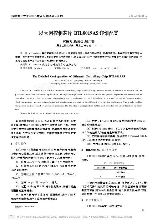
RTL8019型控制器与DSP的接口设计及编程技巧
嵌入式处理器+网卡芯片RTL8019

——ARM与C/OS-Ⅱ
基本概念及设计方法
1
一、嵌入式系统硬件基础
冯· 诺依曼体系结构和哈佛体系结构
CISC与RISC
影响CPU性能的因素
存储器系统
I/O接口
2
典型嵌入式系统基本组成-硬件
电源 模块
时钟
外围电路 微处理器
Flash
RAM
MPU
复位
ROM
14
一个典型的USB通讯系统
通用系统模型 HOST系统
PC机中的情况
应用软件+驱动程序 Ms.Win+接口芯片
嵌入式系统应用
驱动代码+嵌入式处理 器+HOST芯片
HUB
DEVICE D U盘
HUB
其他 U盘
HUB
其他
DEVICE
数据采集器
数据采集器
15
二、嵌入式系统软件基础
操作系统的分类 嵌入式实时操作系统
例如,很多基于微处理器的产品采用前后台系统设计,如微波炉 、电话机、玩具等。从省电的角度出发,平时微处理器处在停机状态 ,所有的事都靠中断服务来完成。
20
前后台系统(后台循环、前台中断)
后台 ISR 前台
时间
ISR
ISR
21
代码的临界区
代码的临界区也称为临界区,指处理时不可分割的代码。 一旦这部分代码开始执行,则不允许任何中断打入。
大家生活中常见的与USB有关的东西有:
U盘、移动硬盘、无驱型的MP3(U盘) USB接口的键盘、Mouse、打印机、数码相机……
即插即用,热插拨,系统不需重启便可工作,且易于扩展 (127个)
RTL8019AS使用手册(个人整理)

序言
本资料为个人整理,由于网上和书本上的关于 RTL8019AS 的资料不详细, 而且很杂、很乱,给刚刚入门以太网的新手带来很大的难度。本人在调试过程中 也遇到了许许多多的问题,借鉴于此,所以本人把自己调试过程当中所遇到的问 题和所用到的关于 RTL8019AS 的资料搜集、整理,方便日后查看,同时也给想用 RTL8019AS 接入以太网的朋友提供一些技术支持。本资料在搜集过程当中,大部 分来自网络,所以,在此我对网络上的大侠们表示谢意。
3.1 写 RAM...................................................................................................................................... 13 3.2 读 RAM...................................................................................................................................... 14 4 发送数据包..................................................................................................................................... 14 5 初始化 RTL8019AS.......................................................................................................................... 16 6 RTL8...................................................................................................... 18
RTL8019AS,RTL8029AS如何读写网卡的RAM

要接收和发送数据包都必须读写网卡的内部的16k的ram,必须通过DMA进行读和写.网卡的内部ram是一块双端口的16k字节的ram.所谓双端口就是说有两套总线连结到该ram,一套总线A是网卡控制器读/写网卡上的ram,另一套总线B是单片机读/写网卡上的ram.总线A又叫Local DMA,总线B又叫Remote DMA.上图中虚线框住的部分为Remote DMA,也就是单片机对网卡ram进行读写的总线,对8019来说就是ISA总线.没有框住的部分(左边的部分),就是Local DMA,网卡控制器对网卡ram进行读写的总线.其中的地址总线没有画出来,只画了数据总线.实际在ram的内部还有一些总线仲裁的逻辑,这里也没有画出来.所谓总线仲裁的逻辑就是为了实现两套总线都能进行对ram的读写,而不互相冲突.网卡控制器读写网卡ram(Local DMA)的优先级比单片机读写网卡ram的优先级要高.优先级要高的意思是:1.当两者都要请求控制总线时.Local DMA优先获得控制权.2.高优先级的Local DMA可以中断Remote DMA,而Remote DMA不能中断Local DMA3.在Remote DMA,也就是单片机对网卡ram读写的过程进行中可以被Local DMA 中断,Local DMA中断Remote DMA,然后进行Local DMA的数据传输,Local DMA传输完毕之后继续刚才被中断的Remote DMA,以完成Remote DMA的传输.上图中的Remote就是Remote DMA的传输,Local burst就是Local DMA的传输.图的左边是一个Remote DMA被Local DMA中断的示意图.Remote DMA是等到Local Burst完成之后才结束该次的传输.被打断多久的时间取决于FT1,FT0(是DCR配置寄存器的位)单片机的总线要比网卡的DMA总线慢很多.网卡的DMA总线大概在10Mhz,而单片机的总线大概1Mhz.所以在Remote DMA的过程中不需要特别的等待时序.但是如果使用较快的CPU,比如DSP,ARM等,可能要考虑时序问题.也就是说IOCHRDY(ISA总线的一个信号,RTL8019AS),或者TRDY(PCI总线的信号RTL8029AS) ,是需要考虑连到CPU上,或者做一定的处理.那么对于不快也不慢的AVR单片机来说,要不要接IOCHRDY?估计是要的.因为我不提供avr的上网方案,所以也没有做太多的研究.对于77E58来说可以不接IOCHRDY,因为77E58可以内部设置外部ram的存取的速度.DMA有8位和16位两种.网卡支持这两种DMA,一般我们使用8位的DMA,8位的DMA的接线比较少,同时适合单片机处理.电脑里一般使用16位DMA.有人问到在电脑里如何使用8位的DMA的问题.有些卡自动检测总线上的IOCS16B来选择总线,比如RTL8019as,我试过RTL8019as使用8位DMA在电脑里是失败的.如果真的要在电脑里使用8位的DMA,要把该引脚IOCS16B断开(可以割断),而不连到ISA总线上,这样这些网卡会自动的进行8位的操作(地址译码为10位).对于使用DM9008芯片的网卡,16位DMA传输是由SLOT引脚决定的。
Rtl8019

RTL8019Realtek Full-Duplex EthernetController with Plug and PlayFunction (RealPNP)REALTEK SEMI-CONDUCTOR CO., LTD.HEAD OFFICE1F, NO. 11, INDUSTRY E. RD. IX, SCIENCE-BASEDINDUSTRIAL PARK, HSINCHU 30077, TAIWAN, R.O.C.TEL:886-35-780211 FAX:886-35-776047OFFICE3F, NO. 56, WU-KUNG 6 RD.,TAIPEI HSIEN, TAIWAN, R.O.C.TEL: 886-2-2980098 FAX: 886-2-2980094, 2980097LS003.61995.04.25CONTENTS1. FEATURES32. GENERAL DESCRIPTION43. PIN CONFIGURATION54. PIN DESCRIPTION4.1.Power Pins 64.2.ISA Bus Interface Pins 64.3.Memory Interface Pins (including SRAM, BROM, EEPROM)74.4.Medium Interface Pins 84.5. LED Output Pins 85. REGISTER DESCRIPTIONS5.1. Group 1: NE2000 Registers 95.1.1. Register Table 95.1.2. Register Functions 115.1.2.1. NE2000 Compatible Registers 115.1.2.2. RTL8019 Defined Registers 115.2. Group 2: Plug and Play (PnP) Registers 175.2.1. Card Control Registers 235.2.2. Logical Device Control Registers 255.2.3. Logical Device Configuration Registers 256. FUNCTIONAL DESCRIPTIONS6.1. RTL8019 Configuration Modes 266.2. Plug and Play 286.2.1. Initiation Key 286.2.2. Isolation Protocol 296.2.3. Plug and Play Isolation Sequence 336.2.4. Reading Resource Data 346.3. 9346 Contents 356.4. Local Memory Bus Control 376.5. LED Behaviors 386.6. Loopback Diagnostic Operation 411. FEATURESm100-pin PQFPm Compliant to Ethernet II and IEEE802.3 10Base5, 10Base2, 10BaseTm Software compatible with NE2000 on both 8 and 16-bit slotsm Supports both jumper and jumperless modesm Supports Microsoft's Plug and Play configuration for jumperless modem Supports Full-Duplex Ethernet function to double channel bandwidthm Supports three level power down modes:- Sleep- Power down with internal clock running- Power down with internal clock haltedm Built-in data prefetch function to improve performancem Provides auto-detect capability between integrated 10BaseT transceiver and Attachment Unit Interface (AUI).m Supports auto polarity correction for 10BaseTm Support 8 IRQ linesm Supports 16 I/O base address optionsm Supports 16K, 32K, 64K and 16K-page mode access to BROM (up to 256 pages with 16K bytes/page)m Supports BROM disable command to release memory after remote bootm Use two 8K or single 32K byte SRAM as local buffer memorym Use 9346 (64*16-bit EEPROM) to store resource configurations and ID parametersm Capable of programming blank 9346 on board for manufacturing conveniencem Support 4 diagnostic LED pins with programmable outputs2. General DescriptionThe RTL8019 is a highly integrated Ethernet Controller which offers a simple solution to implement a Plug and Play NE2000 compatible adapter with full-duplex and power down features. With the three level power down control features, the RTL8019 is made to be an ideal choice of the network device for a GREEN PC system. The full-duplex function enables simultaneously transmission and reception on the twisted-pair link to a full-duplex Ethernet switching hub. This feature not only increases the channel bandwidth from 10 to 20 Mbps but also avoids the performance degrading problem due to the channel contention characteristics of the Ethernet CSMA/CD protocol. The Microsoft's Plug and Play function can relieve the users from pains of taking care the adapter's resource configurations such as IRQ, I/O, and memory address, etc. However, for special applications not to be used as a Plug and Play compatible device, the RTL8019 also supports the jumper and proprietary jumperless options.To offer a fully plug and play solution, the RTL8019 provides the auto-detect capability between the integrated 10BaseT transceiver and AUI interface. Besides, the 10BaseT transceiver can automatically correct the polarity error on its receiving pair. Furthermore, 8 IRQ lines and 16 I/O base address options are provided for grand resource configuration flexibility.The RTL8019 supports 16k, 32k & 64k byte BROM. It also offers the page mode function which can support up to 4M-byte BROM within only 16k-byte system memory space. Besides, the BROM disable command is provided to release the BROM memory space for other system usage (e.g. EMM386, etc.) after the BROM program is loaded.3. PIN CONFIGURATION4. PIN DESCRIPTIONS4.1. Power Pins Type Description2, 47, 57,78, 92VDD P+5V DC power15, 35, 44,52, 84GND P Ground4.2. ISA Bus Interface Pins Type Descriptions33AEN I Address Enable. This ISA signal must be low for a validI/O command.3-10INT7-0I/O Interrupt request lines which are mapped to IRQ15, IRQ12,IRQ11, IRQ10, IRQ5, IRQ4, IRQ3, IRQ2/9 respectively.Only one line is selected to reflect the interrupt requests atone time. All other lines are tri-stated. The RTL8019 alsouses these pins as inputs to monitor the actual state of thecorresponding interrupt lines on ISA bus. The result isrecorded in the INTR register, which may be used bysoftware to detect interrupt conflict.34IOCHRDY O This ISA signal is driven low to insert wait cycles to currenthost read/write command.1IOCS16B[SLOT16]I/O Upon power-on reset, this pin acts as an input named SLOT16 to detect whether a 16-bit or 8-bit slot is in use. Todo this, it is connected to a pull-down resistor (about 27KΩ)externally. At the falling edge of RSTDRV, the RTL8019senses this pin's state. If it is sensed high, the adapter isthought to be placed on a 16-bit slot where this pin isconnected to the host's IOCS16B pin, which is typicallypulled up by a 300Ω resistor on the mother board. If it issensed low, the adapter is thought to be placed on an 8-bitslot where this pin is merely pulled low by the 27KΩresistor. After having latched the input state, this pin isswitched as the IOCS16B signal which is an open-drainoutput and is driven low during a 16-bit host data transfer.It is decoded from AEN and SA9-0.29IORB I Host I/O read command.30IOWB I Host I/O write command.32RSTDRV I High active hardware reset signal from the ISA bus. Pulseswith high level less than 800ns are ignored.28-16, 14-11SA19-14,SA11, SA9-0I Host address bus.93-100,43-36SD15-0I/O Host data bus.31SMEMRB I Host memory read command.4.3. Memory Interface Pins (including SRAM, BROM, EEPROM) Type Description 82BCSB O BROM chip select. Active low signal, asserted when BROMis read.79EECS O9346 chip select. Active high signal, asserted when 9346 isread/write.64-77MA13-0O SRAM address bus.83,85-91MD7-0I/O SRAM data bus.[66-73][BA21-14]O BROM address.[83,85-91][BD7-0]I BROM data bus.[74][EESK]O9346 serial data clock[75][EEDI]O9346 serial data input[76][EEDO]I9346 serial data outputThe following pins are defined for jumper options. Theirstates are latched at the falling edge of RSTDRV, then theyare changed to serve as the SRAM bus. Each of them isinternally pulled down by a 100KΩ resistor. Therefore, theinput will be low when left open and high when pulled upby a 10K resistor externally.[64][JP]I When high, this pin selects jumper mode. When low, itselects jumperless modes (including RT jumperless and Plugand Play).[65][PNP]I When it is high in jumperless mode (i.e. JP=low), theRTL8019 is forced into Plug and Play mode regardless ofthe contents of 9346.The following pins are don't care in jumperless mode(JP=low).[66-70][BS4-0]I Select BROM size and base address.[71,73-75][IOS3-0]I Select I/O base address.[76-77][PL1-0]I Select network medium type.[89-91][IRQS2-0]I Select one interrupt line among INT7-0.81MRDB O SRAM read strobe.80MWRB O SRAM write strobe.4.4.Medium Interface Pins Type Description54,53CD+,CD-I This AUI collision input pair carries the differentialcollision input signal from the MAU.56,55RX+,RX-I This AUI receive input pair carries the differential receiveinput signal from the MAU.49,48TX+,TX-O This AUI transmit output pair contains differential linedrivers which send Manchester encoded data to the MAU.These outputs are source followers and require 270 ohmpull-down resistors to GND.59,58TPIN+,TPIN-I This TP input pair receives the 10 Mbits/s differentialManchester encoded data from the twisted-pair wire.45,46TPOUT+,TPOUT-O This pair carries the differential TP transmit output. The output Manchester encoded signals have been pre-distortedto prevent overcharge on the twisted-pair media and thusreduce jitter.50X1I20Mhz crystal or external oscillator input.51X2O Crystal feedback output. This output is used in crystalconnection only. It must be left open when X1 is driven withan external oscillator.4.5. LED Output Pins Type Description60LEDBNC O This pin goes high when RTL8019's medium type is set to10Base2 mode or auto-detect mode with link test failure.Otherwise, this pin is low. This pin can be used to controlthe power of the DC convertor for CX MAU and connectedto an LED to indicate the used medium type.61LED0O When LEDS0 bit (in CONFIG3 register of RTL8019Page3) is 0, this pin acts as LED_COL. When LEDS0=1, itacts as LED_LINK.62,63LED1,LED2O When LEDS1 bit (in CONFIG3 register of RTL8019 Page3)is 0, these 2 pins act as LED_RX & LED_TX respectively.When LEDS1=1, these pins act as LED_CRS & MCSB.Please refer to section 6.5 for details of the lighteningbehavior of all LEDs.[MCSB]O This is the SRAM chip select signal. It goes low to validatethe SRAM read/write operation. When SRAM is notaccessed, this pin goes high to put SRAM into standby modeand thus save power.5. Register DescriptionsThe registers in RTL8019 can be roughly divided into two groups by their address and functions --one for NE2000, the other for Plug and Play (PnP).5.1. Group 1: NE2000 RegistersThis group includes 4 pages of registers which are selected by bit PS0 & PS1 in the CR register. Each page contains 16 registers. Besides those registers compatible with NE2000, the RTL8019 defines some registers for software configuration and feature enhancement.5.1 1. Register TableNo (Hex)Page0Page1Page2Page3[R][W][R/W][R][R][W]00CR CR CR CR CR CR01CLDA0PSTART PAR0PSTART9346CR9346CR02CLDA1PSTOP PAR1PSTOP BPAGE BPAGE03BNRY BNRY PAR2 -CONFIG0 -04TSR TPSR PAR3TPSR CONFIG1CONFIG105NCR TBCR0PAR4 -CONFIG2CONFIG206FIFO TBCR1PAR5 -CONFIG3CONFIG307ISR ISR CURR - - -08CRDA0RSAR0MAR0 -CSNSAV -09CRDA1RSAR1MAR1 - -HLTCLK0A8019ID0RBCR0MAR2 - - -0B8019ID1RBCR1MAR3 -INTR -0C RSR RCR MAR4RCR - -0D CNTR0TCR MAR5TCR - -0E CNTR1DCR MAR6DCR - -0F CNTR2IMR MAR7IMR - -10-17Remote DMA Port18-1F Reset PortNotes: "-" denotes reserved. Registers with names typed in bold italic format are RTL8019 defined registers and are not supported in a standard NE2000 adapter.Page 0 (PS1=0, PS0=0) Type Bit 7Bit 6Bit 5Bit 4Bit 3Bit 2Bit 1Bit 0 00H CR R/W PS1PS0RD2RD1RD0TXP STA STP 01H CLDA0R A7A6A5A4A3A2A1A0 PSTART W A15A14A13A12A11A10A9A802H CLDA1R A15A14A13A12A11A10A9A8 PSTOP W A15A14A13A12A11A10A9A803H BNRY R/W A15A14A13A12A11A10A9A804H TSR R OWC CDH0CRS ABT COL-PTX TPSR W A15A14A13A12A11A10A9A805H NCR R0000NC3NC2NC1NC0 TBCR0W TBC7TBC6TBC5TBC4TBC3TBC2TBC1TBC0 06H FIFO R D7D6D5D4D3D2D1D0 TBCR1W TBC15TBC14TBC13TBC12TBC11TBC10TBC9TBC8 07H ISR R/W RST RDC CNT OVW TXE RXE PTX PRX 08H CRDA0R A7A6A5A4A3A2A1A0 RSAR0W A7A6A5A4A3A2A1A009H CRDA1R A15A14A13A12A11A10A9A8 RSAR1W A15A14A13A12A11A10A9A80AH8019ID0R01010000 RBCR0W RBC7RBC6RBC5RBC4RBC3RBC2RBC1RBC0 0BH8019ID1R01110000 RBCR1W RBC15RBC14RBC13RBC12RBC11RBC10RBC9RBC8 0CH RSR R DFR DIS PHY MPA0FAE CRC PRX RCR W--MON PRO AM AB AR SEP0DH CNTR0R CNT7CNT6CNT5CNT4CNT3CNT2CNT1CNT0 TCR W---OFST ATD LB1LB0CRC 0EH CNTR1R CNT7CNT6CNT5CNT4CNT3CNT2CNT1CNT0 DCR W-FT1FT0ARM LS LAS BOS WTS 0FH CNTR2R CNT7CNT6CNT5CNT4CNT3CNT2CNT1CNT0 IMR W-RDCE CNTE OVWE TXEE RXEE PTXE PRXE Page 1 (PS1=0, PS0=1) Type Bit 7Bit 6Bit 5Bit 4Bit 3Bit 2Bit 1Bit 0 00H CR R/W PS1PS0RD2RD1RD0TXP STA STP 01H PAR0R/W DA7DA6DA5DA4DA3DA2DA1DA0 02H PAR1R/W DA15DA14DA13DA12DA11DA10DA9DA8 03H PAR2R/W DA23DA22DA21DA20DA19DA18DA17DA16 04H PAR3R/W DA31DA30DA29DA28DA27DA26DA25DA24 05H PAR4R/W DA39DA38DA37DA36DA35DA34DA33DA32 06H PAR5R/W DA47DA46DA45DA44DA43DA42DA41DA40 07H CURR R/W A15A14A13A12A11A10A9A8 08H MAR0R/W FB7FB6FB5FB4FB3FB2FB1FB0 09H MAR1R/W FB15FB14FB13FB12FB11FB10FB9FB8 0AH MAR2R/W FB23FB22FB21FB20FB19FB18FB17FB16 0BH MAR3R/W FB31FB30FB29FB28FB27FB26FB25FB24 0CH MAR4R/W FB39FB38FB37FB36FB35FB34FB33FB32 0DH MAR5R/W FB47FB46FB45FB44FB43FB42FB41FB40 0EH MAR6R/W FB55FB54FB53FB52FB51FB50FB49FB48 0FH MAR7R/W FB63FB62FB61FB60FB59FB58FB57FB56ADVANCE INFORMATION RTL8019 Page 2(PS1=1, PS0=0) Type Bit 7Bit 6Bit 5Bit 4Bit 3Bit 2Bit 1Bit 000H CR R/W PS1PS0RD2RD1RD0TXP STA STP01H PSTART R A15A14A13A12A11A10A9A802H PSTOP R A15A14A13A12A11A10A9A803H-04H TPSR R A15A14A13A12A11A10A9A805H-|0BH0CH RCR R--MON PRO AM AB AR SEP0DH TCR R---OFST ATD LB1LB0CRC0EH DCR R-FT1FT0ARM LS LAS BOS WTS0FH IMR R-RDCE CNTE OVWE TXEE RXEE PTXE PRXEPage 3(PS1=1, PS0=1) Type Bit 7Bit 6Bit 5Bit 4Bit 3Bit 2Bit 1Bit 000H CR R/W PS1PS0RD2RD1RD0TXP STA STP01H9346CR R EEM1EEM0--EECS EESK EEDI EEDOW EEM1EEM0--EECS EESK EEDI-02H BPAGE R/W BP7BP6BP5BP4BP3BP2BP1BP003H CONFIG0R----JP BNC0004H CONFIG1R IRQEN IRQS2IRQS1IRQS0IOS3IOS2IOS1IOS0W*IRQEN-------05H CONFIG2R PL1PL0BSELB BS4BS3BS2BS1BS0W*PL1PL0BSELB-----06H CONFIG3R PNP FUDUP LEDS1LEDS0-SLEEP PWRDN ACTIVEBW*-----SLEEP PWRDN-07H TEST1R/W Reserved08H CSNSAV R CSN7CSN6CSN5CSN4CSN3CSN2CSN1CSN009H HLTCLK W HLT7HLT6HLT5HLT4HLT3HLT2HLT1HLT00AH TEST2R/W Reserved0BH INTR R INT7INT6INT5INT4INT3INT2INT1INT00CH-|0FHNote: The registers marked with type='W*' can be written only if bits EEM1=EEM0=1.5.1.2. Register Functions5.1.2.1. NE2000 Compatible RegistersCR:Command Register (00H; Type=R/W)This register is used to select register pages, enable or disable remote DMA operation andissue commands.Bit Symbol Description7, 6PS1, PS0PS1PS0Register Page Remark000NE2000 compatible011NE2000 compatible102NE2000 compatible113RTL8019 Configuration 5-3RD2-0RD2RD1RD0Function000Not allowed001Remote Read010Remote Write011Send Packet1**Abort/Complete remote DMA 2TXP This bit must be set to transmit a packet. It is internally reset either after thetransmission is completed or aborted. Writing a 0 has no effect.1STA The STA bit controls nothing. It only reflects the value written to this bit.POWER UP=0.0STP This bit is the STOP command. When it is set, no packets will be received ortransmitted. POWER UP=1.STA STP Function10Start Command01Stop CommandISR:Interrupt Status Register (07H; Type=R/W in Page0)This register reflects the NIC status. The host reads it to determine the cause of an interrupt.Individual bits are cleared by writing a "1" into the corresponding bit. It must be cleared after power up.Bit Symbol Description7RST This bit is set when NIC enters reset state and is cleared when a start command isissued to the CR. It is also set when receive buffer overflows and is cleared whenone or more packets have been read from the buffer.6RDC Set when remote DMA operation has been completed.5CNT Set when MSB of one or more of the network tally counters has been set.4OVW This bit is set when the receive buffer has been exhausted.3TXE Transmit error bit is set when a packet transmission is aborted due to excessivecollisions.2RXE This bit is set when a packet received with one or more of the following errors:- CRC error- Frame alignment error-Missed packet1PTX This bit indicates packet transmitted with no errors.0PRX This bit indicates packet received with no errors.IMR:Interrupt Mask Register (0FH; Type=W in Page0, Type=R in Page2)All bits correspond to the bits in the ISR register. POWER UP=all 0s. Setting individual bits will enable the corresponding interrupts.DCR:Data Configuration Register (0EH; Type=W in Page0, Type=R in Page2)Bit Symbol Description7-Always 16, 5FT1, FT0FIFO threshold select bit 1 and 0.4ARM Auto-initialize Remote0: Send Packet Command not executed.1: Send Packet Command executed.3LS Loopback Select0: Loopback mode selected. Bits 1 and 2 of the TCR must also beprogrammed for Loopback operation.1: Normal Operation2LAS This bit must be set to zero. NIC only supports dual 16-bit DMA mode.POWER UP =11BOS Byte Order Select0: MS byte placed on MD15-8 and LS byte on MD7-0. (32xxx,80x86)1: MS byte placed on MD7-0 and LS byte on MD15-8. (680x0)0WTS Word Transfer Select0: byte-wide DMA transfer1: word-wide DMA transferTCR: Transmit Configuration Register (0DH; Type=W in Page0, Type=R in Page2)Bit Symbol Description7-Always 1.6-Always 1.5-Always 1.4OFST Collision Offset Enable.3ATD Auto Transmit Disable.0: normal operation1: reception of multicast address hashing to bit 62 disables transmitter,reception of multicast address hashing to bit 63 enables transmitter.2, 1LB1, LB0LB1LB0Mode Remark000Normal Operation011Internal Lookback102External Lookback113External Lookback 0CRC The NIC CRC logic comprises a CRC generator for transmitter and a CRC checker for receiver. This bit controls the activity of the CRC logic. If this bit set,CRC is inhibited by transmitter. Otherwise CRC is appended by transmitter.Conditions CRC Logic ActivitiesCRC Bit Mode CRC Generator CRC Checker0normal enabled enabled1normal disabled enabled0loopback enabled disabled1loopback disabled enabledTSR:Transmit Status Register (04H; Type=R in Page0)This register indicates the status of a packet transmission.Bit Symbol Description7OWC Out of Window Collision. It is set when a collision is detected after a slot time(51.2us). Transmissions are rescheduled as in normal collisions.6CDH CD Heartbeat. The NIC watches for a collision signal (i.e. CD Heartbeat signal) during the first 6.4us of the interframe gap following a transmission. This bit isset if the transceiver fails to send this signal.5-Always 0.4CRS Carrier Sense lost bit is set when the carrier is lost during transmitting a packet.3ABT It indicates the NIC aborted the transmission because of excessive collisions.2COL It indicates the transmission collided with some other station on the network.1-Always 1.0PTX This bit indicates the transmission completes with no errors.RCR:Receive Configuration Register (0CH; Type=W in Page0, Type=R in Page2)Bit Symbol Description7-Always 1.6-Always 1.5MON When monitor mode bit is set, received packets are checked for address match,good CRC and frame alignment but not buffered to memory. Otherwise, packetswill be buffered to memory.4PRO If PRO=1, all packets with physical destination address accepted.If PRO=0, physical destination address must match the node address programmedin PAR0-5.3AM If AM=1, packets with multicast destination address are accepted.If AM=0, packets with multicast destination address are rejected.2AB If AB=1, packets with broadcast destination address are accepted.If AB=0, packets with broadcast destination address are rejected.1AR If AR=1, packets with length fewer than 64 bytes are accepted.If AR=0, packets with length fewer than 64 bytes are rejected.0SEP If SEP=1, packets with receive errors are accepted.If SEP=0, packets with receive errors are rejected.RSR: Receive Status Register (0CH; Type=R in Page0)Bit Symbol Description7DFR Defferring. Set when a carrier or a collision is detected.6DIS Receiver Disabled. When the NIC enters the monitor mode, this bit is set andreceiver is disabled. Reset when receiver is enabled after leaving the monitormode.5PHY PHY bit is set when the received packet has a multicast or broadcast destinationaddress. It is reset when the received packet has a physical destination address.4MPA Missed Packet bit is set when the incoming packet can not be accepted by NICbecause of a lack of receive buffer or if NIC is in monitor mode. IncrementCNTR2 tally counter.3-Always 0.2FAE Frame Alignment Error bit reflects the incoming packet didn't end on a byteboundary and CRC did not match at last byte boundary. Increment CNTR0 tallycounter.1CRC CRC error bit reflects packet received with CRC error. This bit will also be setfor FAE errors. Increment CNTR1 tally counter.0PRX This bit indicates packet received with no errors.CLDA0, 1:Current Local DMA Registers (01H & 02H; Type=R in Page0)These two registers can be read to get the current local DMA address. PSTART:Page Start Register (01H; Type=W in Page0, Type=R in Page 2)The Page Start register sets the start page address of the receive buffer ring. PSTOP:Page Stop Register (02H; Type=W in Page0, Type=R in Page2)The Page Stop register sets the stop page address of the receive buffer ring. BNRY:Boundary Register (03H; Type=R/W in Page0)This register is used to prevent overwrite of the receive buffer ring. It is typicallyused as a pointer indicating the last receive buffer page the host has read.TPSR:Transmit Page Start Register (04H; Type=W in Page0)This register sets the start page address of the packet to the transmitted.TBCR0,1:Transmit Byte Count Registers (05H & 06H; Type=W in Page0)These two registers set the byte counts of the packet to be transmitted.NCR:Number of Collisions Register (05H; Type=R in Page0)The register records the number of collisions a node experiences during a packettransmission.FIFO: First In First Out Register (06H; Type=R in Page0)This register allows the host to examine the contents of the FIFO after loopback. CRDA0, 1:Current Remote DMA Address registers (08H & 09H; Type=R in Page0)These two registers contain the current address of remote DMA.RSAR0,1:Remote Start Address Registers (08H & 09H; Type=W in Page0)These two registers set the start address of remote DMA.RBCR0,1:Remote Byte Count Registers (0AH & 0BH; Type=W in Page0)These two registers se the data byte counts of remote DMA.CNTR0:Frame Alignment Error Tally Counter Register (0DH; Type=R in Page0)CNTR1:CRC Error Tally Counter Register (0EH; Type=R in Page0)CNTR2:Missed Packet Tally Counter Register (0FH; Type=R in Page0)PAR0-5:Physical Address Registers (01H - 06H; Type=R/W in Page1)These registers contain my Ethernet node address and are used to compare thedestination adderss of incoming packets for acceptation or rejection.CURR:Current Page Register (07H; Type=R/W in Page1)This register points to the page address of the first receive buffer page to be used fora packet reception.MAR0-7: Multicast Address Register (08H - 0FH; Type=R/W in Page1)These registers provide filtering bits of multicast addresses hashed by the CRC logic.5.1.2.2. RTL8019 Defined RegistersPage 0 (PS1=0, PS0=0)Two registers are defined to contain the RTL8019 chip ID. Type Bit7-00AH8019ID0R50H (ASCII code of "P")0BH8019ID1R70H (ASCII code of "p")Page 3(PS1=1, PS0=1)Page3 Power Up Values before loading jumper states and 9346 contents Type Bit 7Bit 6Bit 5Bit 4Bit 3Bit 2Bit 1Bit 0 00H CR R/W00100001 01H9346CR R/W00--**** 02H BPAGE R/W00000000 03H CONFIG0R----**00 04H CONFIG1R/W1******* 05H CONFIG2R/W**0***** 06H CONFIG3R/W*****001 07H-08H CSNSAV R00000000 09H HLTCLK W11111111 0AH-0BH INTR R******** -0CH|0FHPage3 Content Descriptions9346CR: 9346 Command Register (01H; Type=R/W except Bit0=R)Bit Symbol Description7-6EEM1-0These 2 bits select the RTL8019 operating mode.EEM1EEM0Operating Mode00Normal (DP8390 compatible)01Auto-load:Entering this mode will make the RTL8019 loadthe contents of 9346 like when the RSTDRVsignal is asserted.This auto-load operation will take about 2ms.After it is completed, the RTL8019 goes back tothe normal mode automatically (EEM1=EEM0=0) and the CR register is reset to 21H.109346 programming:In this mode, both the local & remote DMAoperation of 8390 are disabled. The 9346 can bedirectly accessed via bit3-0 which now reflect thestates of EECS, EESK,EEDI, & EEDO pinsrespectively.11Config register write enable:Before writing to the Page3 CONFIG1-3registers, the RTL8019 must be placed in thismode. This will prevent RTL8019'sconfigurations from accidental change.5-4-Not used.3EECS These bits reflect the state of EECS, EESK, EEDI & EEDO pins in auto-load or2EESK9346 programming mode.1EEDI0EEDOBPAGE:BROM Page Register (02H; Type=R/W)This register selects a BROM page to be read by the host. Totally it can select 256 pages with 16k bytes per page. Thus the maximum BROM size is 256*16k=4M bytes.CONFIG0: RTL8019 Configuration Register 0 (03H; Type=R)Bit Symbol Description7-4-Not used3JP This bit reflects the state of JP input. It, when set, indicates the RTL8019 is injumper mode.2BNC When set, this bit indicates that the RTL8019 is using the 10Base2 thin cable asits networking medium. This bit will be set in the following 2 cases:(1) PL1=PL0=0 (auto-detect) and link test fails(2) PL1=PL0=1 (10 Base 2)1-0-Always 0s.CONFIG1: RTL8019 Configuration Register 1 (04H; Type=R except Bit7=R/W) Bit Symbol Description7IRQEN IRQ Enable:This bit controls the state of the interrupt request line selected by IRQS2-0. Ifthis bit is set, the interrupt line goes high upon an interrupt request and will below when there is no interrupt request.The interrupt line will be forced to tri-state if this bit is reset.This bit's power-up initial value is 1 and may be modified by software ifEEM1=EEM0=1 in 9346CR register.6-4IRQS2-0IRQ Select :These 3 bits select one of INT7-0 to reflect the RTL8019's interrupt requeststatus. All unselected interrupt lines will be tri-stated.IRQS2IRQS1IRQS0Interrupt Line Assigned ISA IRQ000INT0IRQ2/9001INT1IRQ3010INT2IRQ4011INT3IRQ5100INT4IRQ10101INT5IRQ11110INT6IRQ12111INT7IRQ15 3-0IOS3-0Select I/O base address.IOS3IOS2IOS1IOS0I/O Base0000300H0001320H0010340H0011360H1000380H10013A0H10103C0H10113E0H0100200H0101220H0110240H0111260H1100280H11012A0H11102C0H11112E0HCONFIG2: RTL8019 Configuration Register 2 (05H; Type=R except Bit[7:5]=R/W) Bit Symbol Description7-6PL1-0Select network medium types.PL1PL0Medium Type00TP/CX auto-detect(10BaseT link test isenabled)0110BaseT with link testdisabled1010Base51110Base25BSELB This bit, when set, forces the BROM disabled regardless of the contents of BS4-0. Its power-up initial value is 0 and can be modified by software ifEEM1=EEM0=1 in 9346CR register.4-0BS4-0These bits select the BROM size & memory base address.BS4BS3BS2BS1BS0BROM Base & size00***Disabled0 0 0 011111111C000h, 32KC800h, 32KD000h, 32KD800h, 32K0 011111C000h, 64KD000h, 64K1 1 1 1 1 1 1 10111111111111C000h, 16KC400h, 16KC800h, 16KCC00h, 16KD000h, 16KD400h, 16KD800h, 16KDC00h, 16K1 1 1 1 1 1 1 111111111111111111111C000h, PageC400h, PageC800h, PageCC00h, PageD000h, PageD400h, PageD800h, PageDC00h, PageThe RTL8019 supports a special BROM mode: page mode. In page mode, the BROM always occupies 16K-byte host memory space. However the actual BROM size can be up to 4M bytes.The BROM is divided into several 16K-byte pages. The power on boot page is set to page 0 and the program in page 0 is responsible to select the other pages by the BPAGE register and load their programs.In page mode, bits BP7-0 of BPAGE register are mapped to the BA21-14 pins to select the proper BROM page. In other modes, BA21-16 are not used and the BA15-14 outputs are shown in the following table.。
DSP与以太网通信接口设计

i ) 28 个 独 立 可 编 程 的 多 路 复 用 I/ O 引 脚 ; j ) 串 行 通 讯 接 口 ( SCI ) ; k ) 串 行 外 部 设 备 接 口 ( SPI ) 。 1.2 电路框图 以 TMS320F240 作 为 主 控 制 芯 片 , 以 RTL8019AS 为 网 络 接 口 芯 片, 可方便地实现节点间的互联并进而构成分布式控制系统。 硬 件 电 路 框 图 如 图 1 所 示 , 包 括 主 处 理 器 DSP 控 制 芯 片 TMS320F240 、以 太 网 控 制 芯 片 RTL8019AS、驱 动 串 口 通 信 等 单 元 、片 外 扩 展 FLASH 、译 码 电 路 、电 源 模 块 、看 门 狗 电 路 、串 口 等 电 路 。
- 128-
信息科技
中国高新技术企业
一个标准的以太网物理传输帧由七部分组成, 如表 1 所示(单 位: 字节) 。
表 1 以太网的物理传输帧结构表
IEEE802 .3 帧 格 式 如 图 2 所 示 。
图 2 IEEE802 . 3 帧 格 式 除了数据段的长度不定外, 其他部分的长度固定不变。数据段 为 46 — 1500 字 节 , 以 太 网 规 定 整 个 传 输 包 的 最 大 长 度 不 能 超 过 1514 字 节 , ( 14 字 节 为 DA, SA, TYPE ) , 最 小 不 能 小 于 60 字 节 。 除 去 DA, SA, TYPE 的 14 字 节 , 还 必 须 传 输 46 字 节 的 数 据 , 当 数 据 段 的 数 据 不 足 46 字 节 时 需 填 充 , 填 充 字 符 的 个 数 不 包 括 在 长 度 字 段 里 ; 超 过 1500 字 节 时 , 需 拆 成 多 个 帧 传 送 。 事 实 上 , 发 送 数 据 时 , PR 、 SD、FCS 及 填 充 字 段 这 几 个 数 据 段 由 以 太 网 控 制 器 自 动 产 生 ; 而 接 收 数 据 时 , PR 、SD 被 跳 过 , 控 制 器 一 旦 检 测 到 有 效 的 前 序 字 段 ( PR 、 SD) , 就 认 为 接 收 数 据 开 始 。 2.1.2 网络层 网络层负责将数据报从源节点发送到目的节点, 完成网络内的 IP 寻 址 。 其 主 要 协 议 是 IP ( 网 际 协 议 ) 、ARP ( 地 址 解 析 协 议 ) 、 ICMP (因 特 网 控 制 报 文 协 议 )。 IP 协 议 TCP/ IP 的 核 心 部 分 就 是 网 络 层 , 它 主 要 由 IP 协 议 和 ICMP 两 个 协 议 组 成 , 而 IP 协 议 是 TCP/ IP 协 议 族 中 最 为 核 心 的 协 议 。所 有 的 TCP 、UDP 、ICMP 及 IGMP 数 据 都 以 IP 数 据 包 格 式 传 输 。 IP 协 议 有 三 个 重 要 功 能 : 第 一 个 是 分 配 IP 地 址 和 到 达 目 的 主 机 的 包 发 送 ( 路 由 寻 址 ) 功 能 ; 第 二 个 是 IP 包 的 分 割 处 理 功 能 ; 第 三 个是重新构筑处理功能。 ICMP 协 议 ICMP 是 因 特 网 控 制 报 文 协 议 , 用 来 将 数 据 报 出 现 的 问 题 以 发 送 通 知 的 方 式 反 馈 给 发 送 器 , 是 主 机 和 网 关 使 用 的 一 个 机 制 。 在 IP 协议中, 当数据链路发生了故障而造成包不能到达的时候, 使用 ICMP 协 议 能 够 通 知 发 送 端 发 生 了 故 障 , 所 以 ICMP 是 对 IP 协 议 进 行 辅 助 的 协 议 , 可 以 弥 补 IP 协 议 的 不 足 。 它 包 括 差 错 报 告 和 查 询 两 种 类型的报文。 ARP 协 议 ARP 是 解 析 地 址 协 议 , 主 要 完 成 物 理 地 址 的 映 射 , 即 用 来 将 IP 地 址 与 物 理 地 址 联 系 起 来 并 相 互 转 换 。 因 为 IP 地 址 只 是 主 机 在 抽象网络层中的地址, 是不能直接用来通信的, 在实际网络的链路 上 传 输 数 据 帧 时 必 须 转 变 成 MAC 帧 , 所 以 最 终 还 要 使 用 硬 件 物 理 地 址 。这 样 形 成 了 只 能 使 用 IP 地 址 的 上 层 协 议 软 件 和 只 能 使 用 物 理 地 址 的 下 层 设 备 驱 动 程 序 软 件 之 间 的 分 界 线 。ARP 协 议 包 括 静 态 映 射 和 动 态 映 射 , 一 般 采 用 动 态 映 射 。 ARP 软 件 包 由 三 个 组 件 构 成 : 输 出 处 理 模 块 、输 入 处 理 模 块 和 高 速 缓 存 控 制 模 块 。 传输层 传 输 层 包 括 的 主 要 协 议 有 TCP ( 传 输 控 制 协 议 ) 、UDP ( 用 户 数 据 报 协 议 )。 在 TCP/ IP 协 议 族 中 , 实 现 传 输 层 功 能 的 、有 代 表 性 的
以太网控制器RTL8019

以太网控制器RTL8019RTL8019是高度集成的以太网控制器,为即插即用式NE2000兼容网络适配器提供了简易的解决方案.RTL8019共有32个输入输出地址,对应地址偏移量为00h—lFh.RTL8019的内部寄存器是分页的,每个寄存器都是8位.RTL8019的复位RTL8019的复位引脚RSTDRV是高电平有效的复位信号,高电平时间长度需大于800 ns,通常在RSTDRV从高电平回到低电平之后的100ms时,再对RTL8019进行读写操作,以确保完全复位.当处理器复位时,以太网控制器也复位.热复位:为了保证能够完全复位,可以使用热复位方法.18h一1Fh的8个地址,为复位端口,对该端口的偶数地址读或写入任何数,都会引起以太网控制器的复位,这种方式称为热复位.中断状态寄存器中的第7位RST跟复位有关,它的地址为07h,位于第0页,可直接读写.在以太网控制器执行了正确复位之后该位为1.一般在复位之后检查该标志位,以确认是否复位成功.RTL8019寄存器Ⅰ1.命令寄存器CR:地址偏移量是00h,长度为一个字节.位符号描述7,6 PS1,PS0 选择寄存器页00:0页01:1页10:2页11:3页(为RTL8019AS配置)5—3 RD2—0 表示要执行的功能000:不允许;001:远程读取以太网控制器内存;010:远程写入以太网控制器内存;011:发送包1XX:中止/完成远程DMA2 TXP 要发送数据包时,要将该位置1,该位可能在发送完成后或者发送中止时内部清0,对该位写0操作无效1 STA 写STP组合使用0 STP 该位是停止命令.该位被置1,就停止接收或发送任何数据包,上电时该位为1.STA 与STP组合使用,10:启动命令01:停止命令RTL8019寄存器Ⅱ(1)2.与发送/接收相关的寄存器:①PSTART:接收缓冲区的起始页地址(位于01h,在第0页可写,在第2页可读).②PSTOP:接收缓冲区的结束页地址(该页不用于接收,位于02h,在第0页可写,在第2页可读).③BNRY:边界寄存器(作为读指针使用,位于03h,在第0页可读写).这个寄存器用来避免对环形接收缓冲区中数据的错误覆盖,通常用作指针,指向接收缓冲区中已经被读取的最后一个页.④CURR:当前页寄存器(作为写指针使用,位于07h,在第1页可读写).这个寄存器的内容指向接收缓冲区中第一个可用于接收新数据的页面.⑤DCR:数据配置寄存器.将它设置为使用FIFO缓存,普通模式,8位数据传输模式.字节顺序为高位字节在前,低位字节在后.RTL8019寄存器Ⅱ(2)⑥TPSR:为发送页的起始页地址.初始化为指向第一个发送缓冲区的页.⑦RCR :接收配置寄存器,设置为使用接收缓冲区,仅接收与自己地址相匹配的数据包(以及广播地址数据包)和多点播送地址包;小于64字节的包和校验错的数据包将被丢弃.⑧TCR:发送配置寄存器,启用CRC(循环冗余校验)自动生成和校验功能,工作在正常模式.⑨RSAR0,1:对存储器进行操作的起始地址寄存器,RSAR0存放低8位,RSARl存放高8位.⑩RBCR0,1:对存储器操作的字节计数寄存器,RBCR0存放低8位,RBCRl存放高8位.⑩TBCR0,1:发送字节计数器,这两个寄存器设置了要发送数据包中的字节个数.TBCR0存放低8位,TBCRl存放高8位.RTL8019寄存器Ⅲ3.其他寄存器:①IMR:中断屏蔽寄存器,设置成0x00时,屏蔽所有的中断,设置成0xFF将允许中断.②MAR0一MAR8:多点播送地址,可以全写0xFF.③PAGE2的寄存器是只读的,不用设置.PAGE3的寄存器不是NE2000兼容的,所以也不用设置.RAM空间结构以太网控制器含有16KB的RAM,地址为0x4000—0x7FFF,每256个字节称为一页,共有64页._使用0x40—0x45作为以太网控制器的发送缓冲区,共6页.使用0x46~0x5F作为以太网控制器的接收缓冲区,共32页.CURR和BNRY寄存器是以太网数据收发中用到的两个最主要的寄存器,CURR和BNRY主要用来控制缓冲区的存取过程,保证能顺次写入和读出.CURR是以太网控制器写接收缓冲区的指针.BNRY指向接收缓冲区中已经被读取的最后一个页.网卡的物理地址在完成对寄存器的初始化后,还要对以太网控制器的物理地址(即48位的以太网控制器地址)进行设置.RAM地址中的0x0000~0x000B的12字节是网卡的物理地址.网卡的物理地址本应该是6个字节的,这12字节是单双地址重复存储的.0x000B后面的地址存储的是生产厂商的代码和产品标识代码,也是单双地址重复存储的.以太网模块的接口设计Ⅰ配置RTL8019:为了系统的精简,配置RTL8019为非即插即用模式.有着固定的中断,有着固定的端口地址.以太网模块与处理器的接口电路:以太网模块的接口设计Ⅱ1.寄存器地址映射:采用nGCS5作为以太网模块的地址使能位,将以太网卡映射在了系统的Bank5上,地址从0xa000000开始,由此,要在程序中定义RTL8019的寄存器地址.2.书写RTL8019中的页面切换函数,热复位函数(硬件复位之后的一次热复位)和初始化函数(设置接收缓冲区的位置和以太网物理地址,初始化寄存器,设置中断的模式).通过RTL8019传输数据:数据的发送校验,总线数据包的碰撞检测与避免都由芯片自己完成的,我们只需要配置发送数据的物理层地址的源地址,目的地址,数据包类型以及发送的数据就可以进行数据发送了.PSTART 接收缓冲区的起始页的地址。
以太网控制芯片RTL8019AS详细配置
以太网控制芯片RTL8019AS 详细配置苏锦秀,杨庆江,张广璐(黑龙江科技学院 黑龙江哈尔滨 150027)摘 要:R TL8019AS 是目前实现设备接入以太网普遍采用的一种接口控制芯片,在实际应用中最重要的就是对芯片的配置。
为了使广大工程技术人员能够更好地应用该芯片,对R TL8019AS 工作在不同方式下的配置做了详细的说明解释,并总结了在应用中芯片工作在不同方式下的优缺点。
关键词:R TL8019AS ;跳线方式;非跳线方式;工作方式中图分类号:TP368.4 文献标识码:B 文章编号:10042373X (2007)222151203The Detailed Conf iguration of Ethernet Controlling Chip RT L8019ASSU Jinxiu ,YAN G Qingjiang ,ZHAN G Guanglu(Heilongjiang Institute of Science and Technology ,Harbin ,150027,China )Abstract :R TL8019AS is a kind of interface controlling chip which the equipments access to Ethernet in current.In the practical application ,the most important is the chip ′s configuration.In order to enable the general engineers and technicians u 2sing this chip better ,the article gives detailed configuration showing to the R TL8019AS which working under different styles.And summarizes the chip ′s strongpoint and shortcoming working in the different styles in the application.The article enables the general engineers and technicians understand the the chip ′s configuration better ,and provides certain instruction in prac 2tice.K eywords :R TL8019AS ;jumper ;jumperless ;working style收稿日期:2007204223 以太网控制芯片R TL8019AS 以其优良的性能、低兼的价格,在市场上10Mb/s 网卡中占有相当的比例。
软硬件配置方案设计

软硬件配置方案设计很多时候我们需要将软硬件完美结合在一起才能达到目标要求,下面就是为您收集的软硬件配置方案设计的相关文章,希望可以帮到您,如果你觉得不错的话可以分享给更多小伙伴哦!随着现代网络技术的发展,嵌放式系统如单片机、DSP等系统对接入网络的需求日益增加,例如具有远程抄表功能的电表系统、楞以进行远程控制的信息电系统等。
本文采用TI公司的TMS320VC33DSP 芯片设计与Realtek公司的RTL8019网卡的硬件接口电路,并在DSP 中用软件实现TCP/IP协议,使DSP芯片具备上网功能,从而可以用计算机通过网卡与DSP电路板进行大量数据交换并对其进行控制。
1、硬件设计DSP与网卡的硬件接口电路图如图1所示。
DSP的数据总线低16位接ISA网卡的16位数据线,ISA网卡的IOCS16线接高电平,设置网卡为16位的模式。
网卡共有20根地址线。
将A7~A8、A10~A19接地,A0~A6和A9分别接DSP的A0~A7,用到的网卡地址为0240H~025FH,映射到DSP的Page3空间,地址映射为C000C0H~C000DFH。
DSP的Reset信号用于复位网卡,由于DSP的Reset信号低有效,而网卡的Reset信号高有效,故中间应接非门。
DSP的Page3和R/W信号用于选能网卡的读写信号IOR、IOW,实现的逻辑关系如图2所示。
IORQ是网卡的中断9,通过非门后接DSP的INT1引脚。
RTL8019网卡有三种工作方式:第一种为跳线方式,网卡的I/O和中断由跳线决定;第二种为即插即用方式,由软件进行自动配置plugandplay;第三种为免跳线方式,网卡的I/O和中断由外接的93C46里的内容决定。
计算机上一是即插即用方式,为了降低软件编程的复杂度,将网卡设置为跳线方式。
上述所有的译码逻辑都在EPM7129中实现。
74ALVC16425是总线驱动芯片,可实现3.3V到5V的电平转换。
由于TMS320VC33和EPM7128是3.3V的器件,而ISA总线是5V的,所以信号线不能直接连接,需要通过74ALVC164245进行电平转换和隔离。
- 1、下载文档前请自行甄别文档内容的完整性,平台不提供额外的编辑、内容补充、找答案等附加服务。
- 2、"仅部分预览"的文档,不可在线预览部分如存在完整性等问题,可反馈申请退款(可完整预览的文档不适用该条件!)。
- 3、如文档侵犯您的权益,请联系客服反馈,我们会尽快为您处理(人工客服工作时间:9:00-18:30)。
RTL8019型控制器与DSP的接口设计及编程技巧
技术分类:微处理器与DSP | 2008-04-29
来源:国外电子元器件| 作者:张蓬鹳王群张东辉
基于美国TI公司的高速数字信号处理器(DSP),详细描述RTL8019型以太网控制器的性能特点和引脚功能。
同时给出DSP与RTL8019的硬件电路接口设计方法及DSP控制RTL8019进行网络传输的相应软件编程方法。
1 引言
数字信号处理器(DSP)具有先进的并行处理结构,特别适合于信号处理,已经越来越多地应用于工业控制领域和各类仪器仪表的开发设计。
互联网络硬件和软件的迅猛发展使得网络用户呈指数增长,在使用计算机进行网络互联的同时,各种家电设备、仪器仪表以及工业生产中的数据采集与控制设备逐步走向网络化,以便共享网络中庞大的信息资源。
在电子设备日趋网络化的背景下,利用高速数字信号处理器(DSP)控制RTL8019实现以太网通讯具有十分重要的意义。
TMS320F206是TI公司生产的16-bit定点DSP,它有l条程序总线和3条数据总线,采用了改进的哈佛结构,内含高度并行的32-bit算术逻辑单元、16×16-bit 并行硬件乘法器、片内存储器和片内外设,配备了高度专业化的指令集,功耗相当低,特别适合于信号处理。
RTL8019采用100引脚POFP封装,性能优良,价格低。
它支持PnP自动探测.符合EthernetⅡ与IEEE802.3(10Base5、10Base2、10BoseT)标准,内嵌16 KB SRAM,有全双工通信接口,可以通过交换机(HR901170A,即网络接口)在双绞线上同时发送和接收数据,使带宽从l0 MHz增加到20 MHz,是进行以太网通信的理想器件。
本文即结合DSP处理器的特点,详细介绍Realtek公司生产的RTL8019型以太网控制器的硬件电路设计方法及编程技巧。
(RTL8019AS是以太网控制器
HR901170A是以太网接口)
2 RTL8019的主要引脚功能
AEN(34):地址使能引脚,决定电路被分得的地址空间:
INT0-INT7(97~100,1~4):中断请求引脚;
IOCHRDY(35):读/写命令准备引脚;
IOCSl6B(96):8位/16位数据选择引脚,高电平选择16位数据总线,低电平选择8位数据总线;
IORB,IOWB(29,30):I/O端口读命令、写命令;
SMEMRB,SMEMWB(3l,32):寄存器读命令、写命令;
RSTDRV(33):复位信号;
SD0-SDl5(36~43,87,88,90~96):数据线;
SA0-SDl9(5,7~13,15,16,18~27):地址线;
X1(50):20 MHz晶体振荡器或外部晶体振荡器输入引脚;
LEDBNC,LEDO,LEDl,LED2(60~63):网卡状态指示;
TPOUT+、TPOUT-、TPIN-、TPIN+(45,46,58,59);数据发送和接收引脚。
3 寄存器配置
RTL8019有4页寄存器组,每页寄存器组有16个寄存器。
进行网络通信时需要对这些寄存器进行设置。
CR是控制命令寄存器,地址是00H,这个寄存器用来选择寄存器页,控制远程DMA操作。
其中STP(O bit)是停止命令位,PSO、PSl(6 bit、7 bit)是页寄存器选择位,在实际配置寄存器时,首先要指定要配置的寄存器属于哪一页(就是进行PSI和PSO的设置),然后对该页中的寄存器写入配置信息。
PSTART是接收缓冲区起始页位置,地址是01H。
PSTOP是接收缓冲区中止页位置,地址是02H。
BNRY是边界寄存器,地址是03H。
TSR是发送状态寄存器,TPSR是发送缓冲区起始页位置,地址是04H。
NCR是发送期间碰撞次数,地址是05H。
FIFO是回环检测后,查看FIFO内容,地址是06H。
ISR是中断状态寄存器,写“1”清除内部所有寄存器位,地址是07H。
CRDAO,CRDAl是当前的远程DMA地址寄存器,地址是08H、09H。
RBCR0,RBCRl是远程DMA字节计数寄存器,地址是0AH、OBH。
RSR接收状态寄存器,RCR是接收配置寄存器,地址是0CH。
TCR发送配置寄存器,TSR是发送状态寄存器,CNTR0是帧同步错总计数器,地址是0DH。
DCR是数据配置寄存器,CNTRl是CRC错总计数器,地址是0EH。
CNTR2是丢包总计数器,地址是0FH。
远程DMA端口寄存器,地址是10H。
复位端口寄存器,地址是1AH。
要进行网络通信必须对网络控制器的各个寄存器初始化,初始化比较烦琐,但非常重要,它决定网络通信的一些重要参数。
初始化时需要对上述的各个寄存器进行详细配置。
4 硬件接口电路设计
在具体应用中,由于DSP本身的限制,进行了一系列的简化设计。
采用跳线工作方式即网卡的I/0和中断由跳线决定,JP引脚接高电平时选择16位数据总线。
仅通过4条地址线A0-A3选择RTL8019的寄存器地址和存储器地址,控制并实现数据的读取。
LEDBNC、LEDO、LEDl、LED2网卡状态指示引脚连接发光二极管,便于直观判断网卡状态。
通过GAL22V10型逻辑编程器对RTL8019的片选信号进行控制。
(为什么这样设计,为什么不用DSP直接对RTL8019进行片选信号的控制?)具体的硬件接口电路图如图1所示。
(连接到以太网的器件是HR901170A.)
RTL8019型控制器与DSP的接口设计及编程技巧
技术分类:微处理器与DSP | 2008-04-29
来源:国外电子元器件| 作者:张蓬鹳王群张东辉
5 软件编程
TMS320F206的用户可以用汇编语言或C语言进行源程序的编写,用C语言开发出的系统易于维护,可靠性高,可移植性好。
下面介绍用C语言编写的RTL8019的开发程序。
由于篇幅有限,本文仅给出RTL8019的初始化程序和接收包子程序。
void ethernetinit()
6 结束语
本文详细论述了RTL8019的引脚功能、寄存器配置、硬件配置和软件编程方法,这些同样可以作为单片机、微处理器以及PC等其他应用系统对于网络通信设计的直接参考,用户也可以针对自己的特殊需要进行一些特殊设置。
这些方面的研究和逐步推进将为测控领域注入新的生机和活力。