PEMB20115
Pepperl+Fuchs NJ5-18GK-SN 漏Magnetic感应传感器说明书

17-01-24 15:36D a t e o f i s s u e : 2017-01-24250929_e n g .x m lInstructionManual electrical apparatus for hazardous areas Device category 1Gfor use in hazardous areas with gas, vapour and mist EC-T ype Examination CertificateCE marking ATEX marking ¬ II 1G Ex ia IIC T6…T1 G aThe Ex-related marking can also be printed on the enclosed label.Standards EN 60079-0:2012+A11:2013 EN 60079-11:2012 Ignition protection "Intrinsic safety"Use is restricted to the following stated conditions Appropriate typeNJ 5-18GK-SN...Effective internal inductivity C i ≤ 120 nF ; a cable length of 10 m is considered.Effective internal inductance L i≤ 200 µH ; a cable length of 10 m is considered.G eneralThe apparatus has to be operated according to the appropriate data in the data sheet and in this instruction manual. The EU-type examination certificate has to beobserved. The special conditions must be adhered to! The ATEX directive and there-fore the EU-type-examination certificates generally apply only to the use of electrical apparatus under atmospheric conditions.The device has been checked for suitability for use at ambient temperatures of > 60 °C by the named certification authority. The surface temperature of the device remains within the required limits.For the use of apparatus outside of atmospheric conditions, a reduction of the per-missible minimum ignition energies may need to be considered.Ambient temperatureDetails of the correlation between the type of circuit connected, the maximum per-missible ambient temperature, the temperature class, and the effective internal reac-tance values can be found on the EC-type examination certificate. Note: Use the temperature table for category 1 The 20 % reduction in accordance with EN 1127-1 has already been applied to the temperature table for category 1.Installation, commissioningLaws and/or regulations and standards governing the use or intended usage goal must be observed. The intrinsic safety is only assured in connection with an appro-priate related apparatus and according to the proof of intrinsic safety. The associated apparatus must satisfy the requirements of category ia. Because of the risk of igni-tion, which can occur due to faults and/or transient currents in the equipotential bonding system, galvanic isolation is preferable in the supply and signal circuits. Associated apparatus without electrical isolation can only be used if the correspond-ing requirements of IEC 60079-14 are satisfied. If the Ex-related marking is printed only on the supplied label, then this must be attached in the immediate vicinity of the sensor. The sticking surface for the label must be clean and free from grease. The attached label must be legible and indelible, including in the event of possible chem-ical corrosion.Maintenance No changes can be made to apparatus, which are operated in hazardous areas.Repairs to these apparatus are not possible.Special conditionsProtection from mechanical dangerWhen using the device in a temperature range of -60 °C to -20 °C, protect the sensor against the effects of impact by installing an additional enclosure. The information regarding the minimum ambient temperature for the sensor as provided in the datasheet must also be observed.Electrostatic chargeWhen used in group IIC non-permissible electrostatic charges should be avoided on the plastic housing parts. Avoid electrostatic charges that can cause electrostatic dis-charge when installing or operating the device. Information on electrostatic hazards can be found in the technical specification IEC/TS 60079-32-1.Degree of protection required when installing connecting componentsThe connecting parts of the sensor must be set up in such a way that degree of pro-tection IP20, in accordance with lEC 60529, is achieved as a minimum.R e l e a s e d a t e : 2017-01-24 15:36D a t e o f i s s u e : 2017-01-24250929_e n g .x m lInstructionManual electrical apparatus for hazardous areas Device category 2Gfor use in hazardous areas with gas, vapour and mist EC-T ype Examination CertificateCE marking ATEX marking ¬ II 1G Ex ia IIC T6…T1 G aThe Ex-related marking can also be printed on the enclosed label.Standards EN 60079-0:2012+A11:2013 EN 60079-11:2012 Ignition protection "Intrinsic safety"Use is restricted to the following stated conditions Appropriate typeNJ 5-18GK-SN...Effective internal inductivity C i≤ 120 nF ; a cable length of 10 m is considered.Effective internal inductance L i ≤ 200 µH ; a cable length of 10 m is considered.G eneralThe apparatus has to be operated according to the appropriate data in the data sheet and in this instruction manual. The EU-type examination certificate has to beobserved. The special conditions must be adhered to! The ATEX directive and there-fore the EU-type-examination certificates generally apply only to the use of electrical apparatus under atmospheric conditions.The device has been checked for suitability for use at ambient temperatures of > 60 °C by the named certification authority. The surface temperature of the device remains within the required limits.For the use of apparatus outside of atmospheric conditions, a reduction of the per-missible minimum ignition energies may need to be considered.Maximum permissible ambient temperature T amb Details of the correlation between the type of circuit connected, the maximum per-missible ambient temperature, the temperature class, and the effective internal reac-tance values can be found on the EC-type examination certificate.Installation, commissioningLaws and/or regulations and standards governing the use or intended usage goal must be observed. The intrinsic safety is only assured in connection with an appro-priate related apparatus and according to the proof of intrinsic safety. If the Ex-related marking is printed only on the supplied label, then this must be attached in the imme-diate vicinity of the sensor. The sticking surface for the label must be clean and free from grease. The attached label must be legible and indelible, including in the event of possible chemical corrosion.Maintenance No changes can be made to apparatus, which are operated in hazardous areas.Repairs to these apparatus are not possible.Special conditionsProtection from mechanical dangerWhen using the device in a temperature range of -60 °C to -20 °C, protect the sensor against the effects of impact by installing an additional enclosure. The information regarding the minimum ambient temperature for the sensor as provided in the datasheet must also be observed.Degree of protection required when installing connecting componentsThe connecting parts of the sensor must be set up in such a way that degree of pro-tection IP20, in accordance with lEC 60529, is achieved as a minimum.17-01-24 15:36D a t e o f i s s u e : 2017-01-24250929_e n g .x m lInstructionManual electrical apparatus for hazardous areasDevice category 3G (nA) for use in hazardous areas with gas, vapour and mistX CE marking ATEX marking ¬ II 3G Ex nA IIC T6 GcThe Ex-related marking can also be printed on the enclosed label.Standards EN 60079-0:2012+A11:2013, EN 60079-15:2010 Ignition protection category "n"Use is restricted to the following stated conditionsG eneralThe apparatus has to be operated according to the appropriate data in the data sheet and in this instruction manual. The data stated in the data sheet are restricted by this operating instruction! The special conditions must be observed!Installation, commissioningLaws and/or regulations and standards governing the use or intended usage goal must be observed. If the Ex-related marking is printed only on the supplied label, then this must be attached in the immediate vicinity of the sensor. The sticking surface for the label must be clean and free from grease. The attached label must be legible and indel-ible, including in the event of possible chemical corrosion.MaintenanceNo changes can be made to apparatus, which are operated in hazardous areas.Repairs to these apparatus are not possible.Special conditionsMinimum series resistance R V A minimum series resistance R V is to be provided between the power supply voltage and the proximity switch in accordance with the following list. This can also be assured by using a switch amplifier.Maximum operating voltage U BmaxThe maximum permissible operating voltage UB max is restricted to the values in the following list. T olerances are not permissible.Maximum permissible ambient temperature T Umax Values can be obtained from the following list, depending on the max. operating voltage Ub max and the minimum series resistance Rv. at U Bmax =9 V , R V =562 Ω58 °C (136.4 °F) using an amplifier in accordance with EN 60947-5-6 58 °C (136.4 °F)Protection from mechanical danger The sensor must not be exposed to ANY FORM of mechanical danger.Protection from UV lightThe sensor and the connection cable must be protected from damaging UV-radiation. This can be achieved when the sensor is used in internal areas.Protection of the connection cable The connection cable must be prevented from being subjected to tension and torsional loading.Protection against transients Ensure transient protection is provided and that the maximum value of the transient pro-tection (140% of 85 V) is not exceeded.Material selection accessoriesWhen selecting accessories, ensure that the material allows the temperature of the enclosure to rise to up to 70 °C.R e l e a s e d a t e : 2017-01-24 15:36D a t e o f i s s u e : 2017-01-24250929_e n g .x m lInstructionManual electrical apparatus for hazardous areas Device category 3G (ic) for use in hazardous areas with gas, vapour and mistXCE marking ATEX marking ¬ II 3G Ex ic IIC T6…T1 GcThe Ex-related marking can also be printed on the enclosed label.StandardsEN 60079-0:2012+A11:2013 EN 60079-11:2012 Ignition protection category "ic"Use is restricted to the following stated conditions Effective internal inductivity C i≤ 120 nF ; a cable length of 10 m is considered.Effective internal inductance L i≤ 200 µH ; A cable length of 10 m is considered.G eneralThe apparatus has to be operated according to the appropriate data in the data sheet and in this instruction manual. The data stated in the data sheet are restricted by this operating instruction! The special conditions must be observed! The ATEX Directive applies only to the use of apparatus under atmospheric conditions.If you use the device outside atmospheric conditions, consider that the permissible safety parameters should be reduced.Installation, commissioningLaws and/or regulations and standards governing the use or intended usage goal must be observed. The sensor must only be operated with energy-limited circuits, which satisfy the requirements of IEC 60079-11. The explosion group complies with the connected, supplying, power limiting circuit. If the Ex-relevant identification is printed exclusively on the adhesive label provided, this label must be affixed in the immediate vicinity of the sensor! The background surface to which the adhesivelabel is to be applied must be clean and free from grease! The applied label must be dura-ble and remain legible, with due consideration of the possibility of chemical corro-sion!Maintenance No changes can be made to apparatus, which are operated in hazardous areas.Repairs to these apparatus are not possible.Special conditionsfor Pi=34 mW, Ii=25 mA, T6 70 °C (158 °F) for Pi=34 mW, Ii=25 mA, T5 85 °C (185 °F) for Pi=34 mW, Ii=25 mA, T4-T1 100 °C (212 °F) for Pi=64 mW, Ii=25 mA, T6 69 °C (156.2 °F) for Pi=64 mW, Ii=25 mA, T5 84 °C (183.2 °F) for Pi=64 mW, Ii=25 mA, T4-T1 100 °C (212 °F) for Pi=169 mW, Ii=52 mA, T6 51 °C (123.8 °F) for Pi=169 mW, Ii=52 mA, T5 66 °C (150.8 °F) for Pi=169 mW, Ii=52 mA, T4-T1 80 °C (176 °F) for Pi=242 mW, Ii=76 mA, T6 39 °C (102.2 °F) for Pi=242 mW, Ii=76 mA, T5 54 °C (129.2 °F) for Pi=242 mW, Ii=76 mA, T4-T1 61 °C (141.8 °F)Protection from mechanical danger The sensor must not be mechanically damaged.When used in the temperature range below -20 °C the sensor should be protected from knocks by the provision of an additional housing.Connection partsThe connection parts are to be installed, such that a minimum protection class of IP20 is achieved, in accordance with IEC 60529.17-01-24 15:36D a t e o f i s s u e : 2017-01-24250929_e n g .x m lInstructionManual electrical apparatus for hazardous areas Device category 1Dfor use in hazardous areas with combustible dust EC-T ype Examination CertificateCE marking ATEX marking ¬ II 1D Ex ia IIIC T135°C DaThe Ex-related marking can also be printed on the enclosed label.Standards EN 60079-0:2012+A11:2013 EN 60079-11:2012Ignition protection "Intrinsic safety" Use is restricted to the following stated condi-tionsAppropriate typeNJ 5-18GK-SN...Effective internal inductivity C i ≤ 120 nF ; a cable length of 10 m is considered.Effective internal inductance L i≤ 200 µHA cable length of 10 m is considered.G eneralThe apparatus has to be operated according to the appropriate data in the data sheet and in this instruction manual. The EU-type examination certificate has to beobserved. The ATEX directive and therefore the EU-type-examination certificates generally apply only to the use of electrical apparatus under atmospheric conditions.The device has been checked for suitability for use at ambient temperatures of > 60 °C by the named certification authority. The surface temperature of the device remains within the required limits.For the use of apparatus outside of atmospheric conditions, a reduction of the per-missible minimum ignition energies may need to be considered.Permissible ambient temperature rangeDetails of the correlation between the type of circuit connected, the maximum per-missible ambient temperature, the surface temperature, and the effective internal reactance values can be found on the EC-type-examination certificate. The maxi-mum permissible ambient temperature of the data sheet must be noted, in addition, the lower of the two values must be maintained.Installation, commissioningLaws and/or regulations and standards governing the use or intended usage goal must be observed. The intrinsic safety is only assured in connection with an appro-priate related apparatus and according to the proof of intrinsic safety. If the Ex-related marking is printed only on the supplied label, then this must be attached in the imme-diate vicinity of the sensor. The sticking surface for the label must be clean and free from grease. The attached label must be legible and indelible, including in the event of possible chemical corrosion.Maintenance No changes can be made to apparatus, which are operated in hazardous areas.Repairs to these apparatus are not possible.Special conditionsProtection from mechanical dangerWhen using the device in a temperature range of -60 °C to -20 °C, protect the sensor against the effects of impact by installing an additional enclosure. The information regarding the minimum ambient temperature for the sensor as provided in the datasheet must also be observed.Electrostatic chargeAvoid electrostatic charges that can cause electrostatic discharge when installing or operating the device. Information on electrostatic hazards can be found in the techni-cal specification IEC/TS 60079-32-1. Do not attach the nameplate provided in areas where electrostatic charge can build up.Degree of protection required when installing connecting componentsThe connecting parts of the sensor must be set up in such a way that degree of pro-tection IP20, in accordance with lEC 60529, is achieved as a minimum.R e l e a s e d a t e : 2017-01-24 15:36D a t e o f i s s u e : 2017-01-24250929_e n g .x m lInstructionManual electrical apparatus for hazardous areas Device category 3D for use in hazardous areas with combustible dust CertificateCE marking ATEX marking ¬ II 3D Ex tc IIIC T80°C DcThe Ex-related marking can also be printed on the enclosed label.Standards EN 60079-0:2012+A11:2013, EN 60079-31:2014Protection by enclosure "tc" Some of the information in this instruction manual is more specific than the information provided in the datasheet.G eneralThe corresponding datasheets, declarations of conformity, EC-type examination certifi-cates, certifications, and control drawings, where applicable (see datasheets), form an integral part of this document. These documents can be found at . The maximum surface temperature of the device was determined without a layer of dust on the apparatus. Some of the information in this instruction manual is more specific than the information provided in the datasheet.Installation, commissioningLaws and/or regulations and standards governing the use or intended usage goal must be observed. The adhesive label provided must be affixed in the immediate vicinity of the sensor! The surface to which the label is applied must be clean, flat and free from grease! The affixed adhesive label must be readable and durable, taking account of the possibility of chemical corrosion!MaintenanceNo changes can be made to apparatus, which are operated in hazardous areas.Repairs to these apparatus are not possible.Special conditionsMinimum series resistance R V A minimum series resistance RV is to be provided between the power supply voltage and the proximity switch in accordance with the following list. This can also be assured by using a switch amplifier.Maximum operating voltage U BmaxThe maximum permissible operating voltage UBmax must be restricted to the values given in the following list. T olerances are not permitted.Maximum permissible ambient temperature T Umax Values can be obtained from the following list, depending on the max. operating voltage Ub max and the minimum series resistance Rv. at U Bmax =9 V, R V =562 Ω58 °C (136.4 °F) using an amplifier in accordance with EN 60947-5-6 331 KProtection from mechanical danger The sensor must not be exposed to ANY FORM of mechanical danger.Protection from UV lightThe sensor and the connection cable must be protected from damaging UV-radiation. This can be achieved when the sensor is used in internal areas.Protection of the connection cable The connection cable must be prevented from being subjected to tension and torsional loading.Electrostatic chargeAvoid electrostatic charges that can cause electrostatic discharge when installing or operating the device. Information on electrostatic hazards can be found in the technical specification IEC/TS 60079-32-1. Do not attach the nameplate provided in areas where electrostatic charge can build up.。
日本和泉电气端子台选型手册
BN1U-40W
40A
5.5
35A
注 :对应电线为 1.25mm2,但构造上也可连接 2mm2 的电线。
18-10AWG
CSA 标准
额定绝缘电压 通电电流
对应电线
15A
22-14AWG
15A
22-14AWG
35A
18-10AWG
EN 标准 额定绝缘电压 对应电线
通电电流 (mm2)
接线 螺丝
22A
2 (22-14AWG)
端子台
BN1U 型 BN/BNH 系列 BA 系列
2010-09-10
导轨安装式端子台选型指南
分类 系列名称
軌导轨安装式端子台
BN1U 型
具有螺丝弹升及暂时固定功能,且 UL、CSA 认证产品(600V 额定值)
可对应 FW 的端子台
符合 JIS 标准工业用端子台
符合 EN 规格(TÜV)
BN-W/BNH-W 系列
• 请务必在额定值范围内,或遵守规格使用,以免引起触电或火 灾发生。
• 接线螺丝的尺寸以及推荐扭矩如下表所示。
螺丝尺寸
M3 M3.5 M4 M5
扭矩 (N · m)
0.6 ~ 1.0 1.0 ~ 1.3 1.4 ~ 2.0 2.6 ~ 3.7
螺丝尺寸
M6 M8 M10 M12 M16
扭矩 (N · m)
② 使 用 螺 丝 刀 垂 直 下 压 螺 丝 , ③ 延续第二步骤,用螺丝刀拧
将接线螺丝压入导电体。
紧螺丝。
无 需 暂 时 固 定
④ 松开螺丝时,螺丝会笔直弹 升。
②’把螺丝端子压往导电体之后, ③’拧紧螺丝时,请将接线螺丝 接线螺丝会往箭头方向倾斜。 恢复到垂直状态。
IR公司_大功率MOS管选型

I DContinuous Drain Current(A)70°Micro3Surface Mount PackagesV (BR)DSSDrain-to-Source Breakdown Voltage (V)R DS(on)On-State Resistance ()ΩI D Continuous Drain Current 25°C(A)R ΘMax.Thermal Resistance (°C/W)1FaxonDemand Number Case Outline KeyPartNumberPD Max.PowerDissipation (W)N-ChannelLogic LevelIRLML2402*912570.54200.25 1.20.95230H1IRLML2803912580.54300.251.20.93230P-ChannelLogic LevelIRLML6302*912590.54-200.6-0.62-4.8230H1IRLML5103912600.54-300.6-0.61-4.8230* Indicates low VGS(th), which can operate at VGS = 2.7VMeasured at ambient for Micro3, Micro6, Micro8, SO-8, and SOT-223 package styles. All others measured at case.1Micro3SO-8D-PakD -PakSOT-227Micro6SOT-223Micro82 Illustrations not to scaleI DContinuous Drain Current(A)70°Micro6Surface Mount PackagesV (BR)DSSDrain-to-Source Breakdown Voltage (V)R DS(on)On-State Resistance ()ΩI D Continuous Drain Current 25°C(A)R ΘMax.Thermal Resistance (°C/W)1FaxonDemand Number Case Outline KeyPartNumberPD Max.PowerDissipation (W)N-ChannelLogic LevelIRLMS1902915401.7200.10 3.2 2.675H2IRLMS1503915081.7300.103.22.675P-ChannelLogic LevelIRLMS6702*914141.7-200.20-2.3-1.975H2IRLMS5703914131.7-300.20-2.3-1.975* Indicates low VGS(th), which can operate at VGS = 2.7VMeasured at ambient for Micro3, Micro6, Micro8, SO-8, and SOT-223 package styles. All others measured at case.1Micro3SO-8D-PakD -PakSOT-227Micro6SOT-223Micro82 Illustrations not to scaleI DContinuous Drain Current(A)70°Micro8Surface Mount PackagesV (BR)DSSDrain-to-Source Breakdown Voltage (V)R DS(on)On-State Resistance ()ΩI D Continuous Drain Current 25°C(A)R ΘMax.Thermal Resistance (°C/W)1FaxonDemand Number Case Outline KeyPart NumberP D Max.PowerDissipation (W)N-Channel Logic LevelIRF7601* 912611.820 0.035 5.7 4.6 70 H3IRF7603 912621.830 0.035 5.6 4.5 70Dual N-Channel Logic LevelIRF7501* 912651.220 0.135 2.4 1.9 100 H3IRF7503 912661.2530 0.135 2.4 1.9 100P-Channel Logic LevelIRF7604* 912631.8-20 0.09 -3.6 -2.9 70 H3IRF7606 912641.8-30 0.09 -3.6 -2.9 70Dual P-Channel Logic LevelIRF7504* 912671.25-20 0.27 -1.7 -1.4 100 H3IRF7506 912681.25-30 0.27 -1.7 -1.4 100Dual N- and P-Channel Logic LevelIRF7507* 912691.2520 0.1352.4 1.9 100 H3-20 0.27 -1.7 -1.4IRF7509 912701.2530 0.135 2.4 1.9 100-30 0.27 -1.7 -1.4* Indicates low VGS(th), which can operate at VGS = 2.7VMeasured at ambient for Micro3, Micro6, Micro8, SO-8, and SOT-223 package styles. All others measured at case.1Micro3SO-8D-Pak D -PakSOT-227Micro6SOT-223Micro8 2 Illustrations not to scaleI DContinuous Drain Current(A)70°SO-8Surface Mount PackagesV (BR)DSSDrain-to-Source Breakdown Voltage (V)R DS(on)On-State Resistance ()ΩI D Continuous Drain Current 25°C(A)R ΘMax.Thermal Resistance (°C/W)1FaxonDemand Number Case Outline KeyPart Number P D Max.PowerDissipation (W)N-ChannelIRF7413913302.5300.011139.250H4IRF7413A 916132.5300.0135128.450IRF9410915622.5300.0375.850Dual N-ChannelIRF7311914352.0200.029 6.6 5.362.5H4IRF7313914802.0300.029 6.5 5.262.5IRF7333917002.0300.10 3.5 2.862.5917002.0300.050 4.9 3.962.5IRF9956915592.0300.103.52.862.5Dual P-ChannelIRF7314914352.0-200.058-5.3-4.362.5H4IRF7316915052.0-300.058-4.9-3.962.5IRF9953915602.0-300.25-2.3-1.862.5* Indicates low VGS(th), which can operate at VGS = 2.7VMeasured at ambient for Micro3, Micro6, Micro8, SO-8, and SOT-223 package styles. All others measured at case.1Micro3SO-8D-PakD -PakSOT-227Micro6SOT-223Micro82 Illustrations not to scaleI DContinuous Drain Current(A)70°SO-8Surface Mount PackagesV (BR)DSSDrain-to-Source Breakdown Voltage (V)R DS(on)On-State Resistance ()ΩI D Continuous Drain Current 25°C(A)RΘMax.ThermalResistance(°C/W)1FaxonDemand Number Case Outline KeyPart NumberP D Max.PowerDissipation (W)Dual N- and P-ChannelIRF7317 915682.020 0.029 6.6 5.3 62.5 H42.0-20 0.058 -5.3 -4.3 62.5IRF9952 915622.030 0.103.5 2.8 62.5915622.0-30 0.25 -2.3 -1.8 62.5IRF7319 916062.030 0.029 6.5 5.2 62.52.0-30 0.058 -4.9 -3.9 62.5* Indicates low VGS(th), which can operate at VGS = 2.7VMeasured at ambient for Micro3, Micro6, Micro8, SO-8, and SOT-223 package styles. All others measured at case.1Micro3SO-8D-Pak D -PakSOT-227Micro6SOT-223Micro8 2 Illustrations not to scaleI DContinuous Drain Current(A)70°SO-8Surface Mount PackagesV (BR)DSSDrain-to-Source Breakdown Voltage (V)R DS(on)On-State Resistance ()ΩI D Continuous Drain Current 25°C(A)R ΘMax.Thermal Resistance (°C/W)1FaxonDemand Number Case Outline KeyPart Number P D Max.PowerDissipation (W)N-ChannelLogic LevelIRF7401912442.5200.0228.77.050H4IRF7201911002.5300.0307.0 5.650IRF7403912452.5300.0228.55.450Dual N-ChannelLogic LevelIRF7101908712.0200.10 3.5 2.362.5H4IRF7301912382.0200.050 5.2 4.162.5IRF7303912392.0300.050 4.9 3.962.5IRF7103910952.0500.1303.02.362.5P-ChannelLogic LevelIRF7204911032.5-200.060-5.3-4.250H4IRF7404912462.5-200.040-6.7-5.450IRF7205911042.5-300.070-4.6-3.750IRF7406912472.5-300.045-5.8-3.750IRF7416913562.5-300.02-10-7.150* Indicates low VGS(th), which can operate at VGS = 2.7VMeasured at ambient for Micro3, Micro6, Micro8, SO-8, and SOT-223 package styles. All others measured at case.1Micro3SO-8D-PakD -PakSOT-227Micro6SOT-223Micro82 Illustrations not to scaleI DContinuous Drain Current(A)70°SO-8Surface Mount PackagesV (BR)DSSDrain-to-Source Breakdown Voltage (V)R DS(on)On-State Resistance ()ΩI D Continuous Drain Current 25°C(A)R ΘMax.Thermal Resistance (°C/W)1FaxonDemand Number Case Outline KeyPart Number P D Max.PowerDissipation (W)Dual P-ChannelLogic LevelIRF7104910962.0-200.250-2.3-1.862.5H4IRF7304912402.0-200.090-4.3-3.462.5IRF7306912412.0-300.10-3.6-2.962.5Dual N- and P-Channe Logic LevelIRF7307912421.4200.050 4.3 3.490H4-200.090-3.6-2.9IRF7105910972.0250.1093.5 2.862.52-250.25-2.3-1.862IRF7309912432.0300.050 4.9 3.962.5-300.10-3.6-2.9* Indicates low VGS(th), which can operate at VGS = 2.7VMeasured at ambient for Micro3, Micro6, Micro8, SO-8, and SOT-223 package styles. All others measured at case.1Micro3SO-8D-PakD -PakSOT-227Micro6SOT-223Micro82 Illustrations not to scaleI DContinuous Drain Current(A)70°SOT-223Surface Mount PackagesV (BR)DSSDrain-to-Source Breakdown Voltage (V)R DS(on)On-State Resistance ()ΩI D Continuous Drain Current 25°C(A)R ΘMax.Thermal Resistance (°C/W)1FaxonDemand Number Case Outline KeyPart Number P D Max.PowerDissipation (W)N-ChannelIRFL4105913812.1550.045 3.7 3.060H6IRFL110908612.01000.54 1.50.9660IRFL4310913682.11000.20 1.6 1.360IRFL21090868 2.02001.50.960.660IRFL214908622.02502.00.790.560P-ChannelIRFL9110908642.0-1001.2-1.1-0.6960H6N-ChannelLogic LevelIRLL3303913792.1300.031 4.6 3.760H6IRLL014N 914992.1550.14 2.0 1.660IRLL2705913802.1550.043.83.060* Indicates low VGS(th), which can operate at VGS = 2.7VMeasured at ambient for Micro3, Micro6, Micro8, SO-8, and SOT-223 package styles. All others measured at case.1Micro3SO-8D-PakD -PakSOT-227Micro6SOT-223Micro82 Illustrations not to scaleI DContinuous Drain Current(A)100°D-PakSurface Mount PackagesV (BR)DSSDrain-to-Source Breakdown Voltage (V)R DS(on)On-State Resistance ()ΩI D Continuous Drain Current 25°C(A)R ΘMax.Thermal Resistance (°C/W)1FaxonDemand Number Case Outline KeyPart Number P D Max.PowerDissipation (W)N-ChannelIRFR33039164257300.0313321 2.2H7IRFR024N9133638550.0751610 3.3IRFR41059130248550.0452516 2.7IRFR12059131869550.0273723 1.8IRFR11090524251000.54 4.3 2.75IRFR120N 91365391000.219.1 5.8 3.2IRFR391091364521000.11159.5 2.4IRFR2109052625200 1.5 2.6 1.75IRFR22090525422000.8 4.833IRFR21490703252502 2.2 1.45IRFR2249060042250 1.1 3.8 2.43IRFR3109059725400 3.6 1.7 1.15IRFR3209059842400 1.8 3.123IRFR42090599425003 2.4 1.53IRFRC2090637426004.421.33* Indicates low VGS(th), which can operate at VGS = 2.7VMeasured at ambient for Micro3, Micro6, Micro8, SO-8, and SOT-223 package styles. All others measured at case.1Micro3SO-8D-PakD -PakSOT-227Micro6SOT-223Micro82 Illustrations not to scaleI DContinuous Drain Current(A)100°D-PakSurface Mount PackagesV (BR)DSSDrain-to-Source Breakdown Voltage (V)R DS(on)On-State Resistance ()ΩI D Continuous Drain Current 25°C(A)R ΘMax.Thermal Resistance (°C/W)1FaxonDemand Number Case Outline KeyPart Number P D Max.PowerDissipation (W)P-ChannelIRFR55059161057-550.11-18-11 2.2H7IRFR53059140289-550.065-28-18 1.4IRFR90149065425-600.5-5.1-3.25IRFR90249065542-600.28-8.8-5.63IRFR91109051925-100 1.2-3.1-25IRFR91209052042-1000.6-5.6-3.63IRFR9120N 9150739-1000.48-6.5-4.1 3.2IRFR92109052125-2003-1.9-1.25IRFR92209052242-200 1.5-3.6-2.33IRFR92149165850-250 3.0-2.7-1.7 2.5IRFR93109166350-4007.0-1.8-1.12.5* Indicates low VGS(th), which can operate at VGS = 2.7VMeasured at ambient for Micro3, Micro6, Micro8, SO-8, and SOT-223 package styles. All others measured at case.1Micro3SO-8D-PakD -PakSOT-227Micro6SOT-223Micro82 Illustrations not to scaleI DContinuous Drain Current(A)100°D-PakSurface Mount PackagesV (BR)DSSDrain-to-Source Breakdown Voltage (V)R DS(on)On-State Resistance ()ΩI D Continuous Drain Current 25°C(A)R ΘMax.Thermal Resistance (°C/W)1FaxonDemand Number Case Outline KeyPart Number P D Max.PowerDissipation (W)N-ChannelLogic LevelIRLR27039133538300.0452214 3.3H7IRLR33039131657300.0313321 2.2IRLR31039133369300.0194629 1.8IRLR024N 9136338550.0651711 3.3IRLR27059131746550.042415 2.7IRLR29059133469550.0273623 1.8IRLR120N 91541391000.18511 6.9 3.2IRLR341091607521000.10159.52.4* Indicates low VGS(th), which can operate at VGS = 2.7VMeasured at ambient for Micro3, Micro6, Micro8, SO-8, and SOT-223 package styles. All others measured at case.1Micro3SO-8D-PakD -PakSOT-227Micro6SOT-223Micro82 Illustrations not to scaleI DContinuous Drain Current(A)100°D 2PakSurface Mount PackagesV (BR)DSSDrain-to-Source Breakdown Voltage (V)R DS(on)On-State Resistance ()ΩI D Continuous Drain Current 25°C(A)R ΘMax.Thermal Resistance (°C/W)1FaxonDemand Number Case Outline KeyPart NumberP D Max.PowerDissipation (W)N-ChannelIRFZ24NS 913554555 0.07 17 12 3.3 H10IRFZ34NS 913116855 0.04 29 20 2.2IRFZ44NS 9131511055 0.022 49 35 1.4IRFZ46NS 9130512055 0.020 53 37 1.3IRFZ48NS 9140814055 0.016 64 45 1.1IRF1010NS 913723.855 0.011 84 60 40IRF3205S 9130420055 0.008 110 80 0.75IRFZ44ES 9171411060 0.023 48 34 1.4IRF1010ES 9172017060 0.012 83 59 0.90IRF2807S 9151815075 0.013 71 50 1.0IRF520NS 9134047100 0.2 9.5 6.7 3.2IRF530NS 9135263100 0.11 15 11 2.4IRF540NS 91342110100 0.052 27 19 1.6IRF1310NS 91514120100 0.036 36 25 1.3IRF3710S 91310150100 0.028 46 33 1.0IRF3315S 9161794150 0.082 21 15 1.6IRF3415S 91509150150 0.042 37 26 1.0IRFBC20S 9.101450600 4.4 2.2 1.4 2.5IRFBC30S 9101574600 2.2 3.6 2.3 1.7IRFBC40S 91016130600 1.2 6.2 3.9 1.0* Indicates low VGS(th), which can operate at VGS = 2.7VMeasured at ambient for Micro3, Micro6, Micro8, SO-8, and SOT-223 package styles. All others measured at case.1Micro3SO-8D-Pak D -PakSOT-227Micro6SOT-223Micro8 2 Illustrations not to scaleI DContinuous Drain Current(A)100°D 2PakSurface Mount PackagesV (BR)DSSDrain-to-Source Breakdown Voltage (V)R DS(on)On-State Resistance ()ΩI D Continuous Drain Current 25°C(A)R ΘMax.Thermal Resistance (°C/W)1FaxonDemandNumberCase Outline KeyPart NumberP D Max.PowerDissipation (W)IRFBF20S 9166554900 8.0 1.7 1.1 2.3 H10P-ChannelIRF5305S 91386110-55 0.06 -31 -22 1.4 H10IRF4905S 914783.8-55 0.02 -74 -52 40IRF9520NS 9152247-100 0.48 -6.7 -4.8 3.2IRF9530NS 9152375-100 0.20 -14 -9.9 2.0IRF9540NS 9148394-100 0.117 -19 -13 1.6IRF5210S 91405150-100 0.06 -35 -25 1.0* Indicates low VGS(th), which can operate at VGS = 2.7VMeasured at ambient for Micro3, Micro6, Micro8, SO-8, and SOT-223 package styles. All others measured at case.1Micro3SO-8D-Pak D -PakSOT-227Micro6SOT-223Micro8 2 Illustrations not to scaleI DContinuous Drain Current(A)100°D 2PakSurface Mount PackagesV (BR)DSSDrain-to-Source Breakdown Voltage (V)R DS(on)On-State Resistance ()ΩI D Continuous Drain Current 25°C(A)R ΘMax.Thermal Resistance (°C/W)1FaxonDemand Number Case Outline KeyPart NumberP D Max.PowerDissipation (W)N-Channel Logic LevelIRL3302S 916925720 0.020 39 25 2.2 H10IRL3202S916756920 0.016 48 30 1.8IRL3102S 916918920 0.013 61 39 1.4IRL3402S 9169311020 0.01 85 54 1.1IRL3502S 9167614020 0.007 110 67 0.89IRL2703S 913604530 0.04 24 17 3.3IRL3303S 913236830 0.026 38 27 2.2IRL3103S 9133811030 0.014 64 45 1.4IRL2203NS 9136717030 0.007 116 82 0.90IRL3803S 9131920030 0.006 140 98 0.75IRLZ24NS 913584555 0.06 18 13 3.3IRLZ34NS 913086855 0.035 30 21 2.2IRLZ44NS 9134711055 0.022 47 33 1.4IRL3705NS 9150217055 0.01 89 63 0.90IRL2505S 9132620055 0.008 104 74 0.75IRLZ44S 9090615060 0.028 50 36 1.0IRL530NS 9134963100 0.1 15 11 2.4IRL2910S 91376150100 0.026 48 34 1.0* Indicates low VGS(th), which can operate at VGS = 2.7VMeasured at ambient for Micro3, Micro6, Micro8, SO-8, and SOT-223 package styles. All others measured at case.1Micro3SO-8D-Pak D -PakSOT-227Micro6SOT-223Micro8 2 Illustrations not to scaleI DContinuous Drain Current(A)100°SOT-227Surface Mount PackagesV (BR)DSSDrain-to-Source Breakdown Voltage (V)R DS(on)On-State Resistance ()ΩI D Continuous DrainCurrent 25°C(A)RΘMax.Thermal Resistance (°C/W)1FaxonDemand Number Case Outline KeyPart Number P D Max.PowerDissipation (W)N-ChannelFully Isolated Low ChargeFA38SA50LC 916155005000.1338240.25H21FA57SA50LC916506255000.0857360.20* Indicates low VGS(th), which can operate at VGS = 2.7VMeasured at ambient for Micro3, Micro6, Micro8, SO-8, and SOT-223 package styles. All others measured at case.1Micro3SO-8D-PakD -PakSOT-227Micro6SOT-223Micro82 Illustrations not to scaleI DContinuous Drain Current(A)100°I-PakThrough-Hole PackagesV (BR)DSSDrain-to-Source Breakdown Voltage (V)R DS(on)On-State Resistance ()ΩI D Continuous Drain Current 25°C(A)R ΘMax.Thermal Resistance (°C/W)1FaxonDemand Number Case Outline KeyPart Number P D Max.PowerDissipation (W)N-ChannelIRFU33039164257300.0313321 2.2H8IRFU024N 9133638550.0751610 3.3IRFU41059130248550.0452519 2.7IRFU12059131869550.0273723 1.8IRFU11090524251000.54 4.3 2.7 5.0IRFU120N 91365391000.219.1 5.8 3.2IRFU391091364521000.11159.5 2.4IRFU2109052625200 1.5 2.6 1.7 5.0IRFU22090525422000.80 4.8 3.0 3.0IRFU2149070325250 2.0 2.2 1.4 5.0IRFU2249060042250 1.1 3.8 2.4 3.0IRFU3109059725400 3.6 1.7 1.1 5.0IRFU3209059842400 1.8 3.1 2.0 3.0IRFU4209059942500 3.0 2.4 1.5 3.0IRFUC2090637426004.42.01.33.0I-PakTO-220 FullPakTO-262TO-247HEXDIPTO-220AB Illustrations not to scale** Not ratedI DContinuous Drain Current(A)100°I-PakThrough-Hole PackagesV (BR)DSSDrain-to-Source Breakdown Voltage (V)R DS(on)On-State Resistance ()ΩI D Continuous Drain Current 25°C(A)R ΘMax.Thermal Resistance (°C/W)1FaxonDemand Number Case Outline KeyPart Number P D Max.PowerDissipation (W)P-ChannelIRFU55059161057-550.11-18-11 2.2H8IRFU53059140289-550.065-28-18 1.4IRFU90149065425-600.50-5.1-3.2 5.0IRFU90249065542-600.28-8.8-5.6 3.0IRFU91109051925-100 1.2-3.1-2.0 5.0IRFU91209052042-1000.60-5.6-3.6 3.0IRFU9120N 9150739-1000.48-6.5-4.1 3.2IRFU92109052125-200 3.0-1.9-1.2 5.0IRFU92209052242-200 1.5-3.6-2.3 3.0IRFU92149165850-2503.0-2.7-1.7 2.5IRFU93109166350-4007.0-1.8-1.12.5N-ChannelLogic LevelIRLU27039133538300.0452214 3.3H8IRLU33039131657300.0313321 2.2IRLU31039133369300.0194629 1.8IRLU024N 9136338550.0651711 3.3IRLU27059131746550.04241715IRLU29059133469550.0273623 1.8IRLU120N 91541391000.18511 6.9 3.2IRLU341091607521000.10159.52.4I-PakTO-220 FullPakTO-262TO-247HEXDIPTO-220AB Illustrations not to scale** Not ratedI DContinuous Drain Current(A)100°HEXDIPThrough-Hole PackagesV (BR)DSSDrain-to-Source Breakdown Voltage (V)R DS(on)On-State Resistance ()ΩI D Continuous Drain Current 25°C(A)R ΘMax.Thermal Resistance (°C/W)1FaxonDemand Number Case Outline KeyPart Number P D Max.PowerDissipation (W)N-ChannelIRFD014907001.3600.2 1.7 1.2120H9IRFD024906991.3600.1 2.5 1.8120IRFD110903281.31000.54 1.00.71120IRFD120903851.31000.27 1.30.94120IRFD210903861.3200 1.50.60.38120IRFD220904171.32000.80.80.50120IRFD214912711.3250 2.00.570.32120IRFD224912721.3250 1.10.760.43120IRFD310912251.3400 3.60.420.23120IRFD320912261.3400 1.80.600.33120IRFD420912271.3500 3.00.460.26120IRFDC20912281.36004.40.320.21120I-PakTO-220 FullPakTO-262TO-247HEXDIPTO-220AB Illustrations not to scale** Not ratedI D Continuous Drain Current (A)100°TO-220Qg TotalGate Charge(nC)Through-Hole PackagesV (BR)DSSDrain-to-Source Breakdown Voltage (V)R DS(on)On-State Resistance ()ΩI D Continuous Drain Current 25°C (A)R ΘMax.Thermal Resistance(°C/W)1Faxon Demand Number Case OutlineKeyPart Number P D Max.Power Dissipation (W)N-ChannelLow ChargeIRF737LC91314743000.75 6.1** 1.7 3.9H11IRF740LC 910681254000.5510** 1.039IRF840LC 910691255000.858.0** 1.039IRFBC40LC910701256001.26.2**1.039I-PakTO-220 FullPakTO-262TO-247HEXDIPTO-220AB Illustrations not to scale** Not ratedI DContinuous Drain Current(A)100°TO-220ABThrough-Hole PackagesV (BR)DSSDrain-to-Source Breakdown Voltage (V)R DS(on)On-State Resistance ()ΩI D Continuous Drain Current 25°C(A)R ΘMax.Thermal Resistance (°C/W)1FaxonDemand Number Case Outline KeyPart Number P D Max.PowerDissipation (W)N-ChannelIRFZ24N 9135445550.071712 3.3H12IRFZ34N9127656550.042618 2.7IRFZ44N 9130383550.0244129 1.8IRFZ46N 9127788550.024633 1.7IRFZ48N 9140694550.0165337 1.6IRF1010N 91278130550.0127251 1.2IRF320591279150550.0089869 1.0IRFZ34E 9167268600.0422820 2.2IRFZ44E 91671110600.0234834 1.4IRF1010E 91670170600.01281570.90IRF280791517150750.0137150 1.0IRF520N 91339471000.209.5 6.79.5IRF530N 91351601000.111511 2.4IRF540N 91341941000.0522719 1.6IRF1310N 916111201000.0363625 1.3IRF3710913091501000.0284633 1.0IRF331591623941500.0822115 1.6IRF3415914771501500.0423726 1.0IRFBC209062350600 4.4 2.2 1.4 2.5IRFBC309048274600 2.2 3.6 2.3 1.7IRFBC4090506125600 1.2 6.2 3.9 1.0IRFBE2090610548006.51.81.22.3I-PakTO-220 FullPakTO-262TO-247HEXDIPTO-220AB Illustrations not to scale** Not ratedI DContinuous Drain Current(A)100°TO-220ABThrough-Hole PackagesV (BR)DSSDrain-to-Source Breakdown Voltage (V)R DS(on)On-State Resistance ()ΩI D Continuous Drain Current 25°C(A)R ΘMax.Thermal Resistance (°C/W)1FaxonDemand Number Case Outline KeyPart Number P D Max.PowerDissipation (W)IRFBE3090613125800 3.0 4.1 2.6 2.0H12IRFBF3090616125900 3.7 3.6 2.3 1.0IRFBG209060454100011 1.40.86 2.3IRFBG309062012510005.03.12.01.0P-ChannelIRF9Z24N 9148445-550.175-12-8.53.3H12IRF9Z34N 9148556-550.10-17-12 2.7IRF530591385110-550.06-31-22 1.4IRF490591280150-550.02-64-45 1.0IRF9530N 9148275-1000.20-13-9.2 2.0IRF9540N 9143794-1000.117-19-13 1.6IRF521091434150-1000.06-35-25 1.0IRF62159147983-1500.29-11-7.81.8I-PakTO-220 FullPakTO-262TO-247HEXDIPTO-220AB Illustrations not to scale** Not ratedI DContinuous Drain Current(A)100°TO-220ABThrough-Hole PackagesV (BR)DSSDrain-to-Source Breakdown Voltage (V)R DS(on)On-State Resistance ()ΩI D Continuous Drain Current 25°C(A)R ΘMax.Thermal Resistance (°C/W)1FaxonDemand Number Case Outline KeyPart NumberP D Max.PowerDissipation (W)N-Channel Logic LevelIRL3302 916965720 0.020 39 25 2.2 H12IRL3202 916956920 0.016 48 30 1.8IRL3102 916948920 0.013 61 39 1.4IRL3402 9169711020 0.01 85 54 1.1IRL3502 9169814020 0.007 110 67 0.89IRL2703 913594530 0.04 24 17 3.3IRL3303 913225630 0.026 34 24 2.7IRL3103 913378330 0.014 56 40 1.8IRL2203N 9136613030 0.007 100 71 1.230 0.007 61 43 3.2IRL3803 9130115030 0.006 120 83 1.0IRLZ24N 913574555 0.06 18 13 3.3IRLZ34N 913075655 0.035 27 19 2.7IRLZ44N 913468355 0.022 41 29 1.8IRL3705N 9137013055 0.01 77 54 1.2IRL2505 9132520055 0.008 104 74 0.75IRL520N 9149447100 0.18 10 7.1 3.2IRL530N 9134863100 0.10 15 11 2.4IRL540N 9149594100 0.044 30 21 1.6IRL2910 91375150100 0.026 48 34 1.0I-PakTO-220 FullPakTO-262TO-247HEXDIPTO-220AB Illustrations not to scale** Not ratedI D Continuous Drain Current (A)100°TO-220 FullPak (Fully Isolated)Qg TotalGate Charge(nC)Through-Hole PackagesV (BR)DSSDrain-to-Source Breakdown Voltage (V)R DS(on)On-State Resistance ()ΩI D Continuous DrainCurrent 25°C(A)R ΘMax.Thermal Resistance (°C/W)1Fax on Demand Number Case OutlineKeyPart Number P D Max.Power Dissipation (W)N-ChannelLow ChargeIRFI740GLC91209404000.55 6.0** 3.139H13IRFI840GLC 91208405000.85 4.8** 3.139IRFIBC40GLC91211406001.24.0**3.139I-PakTO-220 FullPakTO-262TO-247HEXDIPTO-220AB Illustrations not to scale** Not ratedI DContinuous Drain Current(A)100°TO-220 FullPak (Fully Isolated)Through-Hole PackagesV (BR)DSSDrain-to-Source Breakdown Voltage (V)R DS(on)On-State Resistance ()ΩI D Continuous Drain Current 25°C(A)R ΘMax.Thermal Resistance (°C/W)1FaxonDemand Number Case Outline KeyPart Number P D Max.PowerDissipation (W)N-ChannelIRFIZ24N 9150126550.07139.2 5.8H14IRFIZ34N9148931550.041913 4.8IRFIZ44N 9140338550.02428200.024IRFIZ46N 9130640550.023122 3.8IRFIZ48N 9140742550.0163625 3.6IRFI1010N 9137347550.0124431 3.2IRFI32059137448550.0085640 3.1IRFIZ24E 9167329600.071149.6 5.2IRFIZ34E 9167437600.0422115 4.1IRFI510G 90829271000.54 4.5 3.2 5.5IRFI520N 91362271000.207.2 5.1 5.5IRFI530N 91353331000.11117.8 4.5IRFI540N 91361421000.0521813 3.6IRFI1310N 91611451000.0362216 3.3IRFI371091387481000.0252820 3.1IRFI620G 90832302000.8 4.1 2.6 4.1IRFI630G 90652322000.4 5.9 3.7 3.6IRFI640G 90649402000.189.8 6.2 3.1IRFI614G 9083123250 2.0 2.1 1.3 5.5IRFI624G 9083330250 1.1 3.4 2.2 4.1IRFI634G 90738322500.45 5.6 3.5 3.6IRFI644G 90739402500.287.953.1I-PakTO-220 FullPakTO-262TO-247HEXDIPTO-220AB Illustrations not to scale** Not ratedI DContinuous Drain Current(A)100°TO-220 FullPak (Fully Isolated)Through-Hole PackagesV (BR)DSSDrain-to-Source Breakdown Voltage (V)R DS(on)On-State Resistance ()ΩI D Continuous Drain Current 25°C(A)R ΘMax.Thermal Resistance (°C/W)1FaxonDemand Number Case Outline KeyPart Number P D Max.PowerDissipation (W)IRFI720G 9083430400 1.8 2.6 1.7 4.1H14IRFI730G 9065032400 1.0 3.7 2.3 3.6IRFI740G 90651404000.55 5.4 3.4 3.1IRFI734G 9100135450 1.2 3.4 2.1 3.6IRFI744G 91002404500.63 4.9 3.1 3.1IRFI820G 9064130500 3.0 2.1 1.3 4.1IRFI830G 9064632500 1.5 3.12 3.6IRFI840G 90642405000.85 4.6 2.9 3.1IRFIBC20G 90850306004.41.71.1 4.1IRFIBC30G 90851356002.2 2.5 1.63.6IRFIBC40G 9085240600 1.2 3.5 2.2 3.1IRFIBE20G 9085330800 6.5 1.4.86 4.1IRFIBE30G 9085435800 3.0 2.1 1.4 3.6IRFIBF20G 90855309008.0 1.2.79 4.1IRFIBF30G90856359003.71.91.23.6P-ChannelIRFI9Z24N 9152929-550.175-9.5-6.7 5.2H14IRFI9Z34N 9153037-550.10-14-10 4.1IRFI49059152663-550.02-41-29 2.4IRFI9540G 9083742-1000.117-13-9.2 3.6IRFI9540N 9148742-1000.117-13-9.2 3.6IRFI52109140448-1000.06-20-14 3.1IRFI9634G 9148835-2501.0-4.1-2.63.6I-PakTO-220 FullPakTO-262TO-247HEXDIPTO-220AB Illustrations not to scale** Not ratedI DContinuous Drain Current(A)100°TO-220 FullPak (Fully Isolated)Through-Hole PackagesV (BR)DSSDrain-to-Source Breakdown Voltage (V)R DS(on)On-State Resistance ()ΩI D Continuous Drain Current 25°C(A)R ΘMax.Thermal Resistance (°C/W)1FaxonDemand Number Case Outline KeyPart Number P D Max.PowerDissipation (W)N-ChannelLogic LevelIRLI2203N 9137847300.0076143 3.2H14IRLI38039132048300.0066747 3.1IRLIZ24N 9134426550.06149.9 5.8IRLIZ34N 9132931550.0352014 4.8IRLIZ44N 9149838550.0222820 4.0IRLI3705N 9136947550.014733 3.2IRLI25059132763550.00858412.4IRLI520N 91496271000.187.7 5.4 5.5IRLI530N 91350331000.10117.8 4.5IRLI540N 91497421000.04420143.6IRLI291091384481000.02627193.1P-ChannelLogic LevelIRFI9520G 9083537-1000.6-5.2-3.6 4.1H14IRFI9530G 9083638-1000.03-7.7-5.4 3.6IRFI9620G 9087430-200 1.5-3.0-1.9 4.1IRFI9630G 9083840-2000.8-4.3-2.7 3.6IRFI9640G9083940-2000.5-6.1-3.93.1I-PakTO-220 FullPakTO-262TO-247HEXDIPTO-220AB Illustrations not to scale** Not ratedI D Continuous Drain Current (A)100°TO-247Qg TotalGate Charge(nC)Through-Hole PackagesV (BR)DSSDrain-to-Source Breakdown Voltage (V)R DS(on)On-State Resistance ()ΩI D Continuous Drain Current 25°C (A)R ΘMax.Thermal Resistance (°C/W)1Fax on Demand Number Case OutlineKeyPart Number P D Max.Power Dissipation (W)1N-ChannelLow ChargeIRFP350LC912291904000.3018**0.6570H16IRFP360LC 912302804000.2023**0.4598IRFP450LC 912311905000.4016**0.6570IRFP460LC 912322805000.2720**0.4598IRFPC50LC 912331906000.6013**0.6570IRFPC60LC912342806000.4016**0.4598I-PakTO-220 FullPakTO-262TO-247HEXDIPTO-220AB Illustrations not to scale** Not rated。
宝钢与日系及部分汽车专用钢板牌号对照
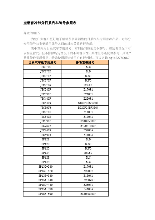
宝钢普冷部分日系汽车牌号参照表
尊敬的用户:
为使广大客户更好地了解钢贸公司销售的日系汽车专用普冷产品,对部分专用牌号与宝钢通用牌号之间的对应关系进行告示:
表中左列为日系汽车专用牌号,右列是对应的宝钢牌号,在通常情况下可以相互替代,但不排除特定情况下的不可替代性,其冲压等级仅供参考,具体产
热镀锌汽车标准对应关系公告
尊敬的宝时达用户:为使广大客户更好地了解钢贸公司销售的汽车热镀锌产品,对部分专用牌号与宝钢通用牌号之间的对应关系进行告示:
表中右列为汽车专用牌号,左列是对应的宝钢牌号,在通常情况下可以相互替代,但不排除特定情况下的不可替代性,其冲压等级仅供参考,具体产品性能详见质保书,特殊使用用途请用户自行判断。
Sensata技术有限公司的感应器产品介绍说明书
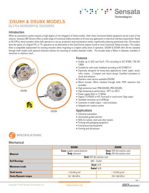
|DSU9H & DSU9X MODELSSIL3 PLe INCREMENTAL ENCODERS SPECIFICATIONSFeatures•Usable up to SIL3 and Cat.4 / PLe according to IEC 61508 / EN ISO 13849•Suitable for safe motor feedback according to IEC 61800-5-2•E specially designed for heavy-duty applications (steel, paper, wood,mills, cranes…) Compact and robust design. Excellent resistance to shock and vibration•Stainless steel version available (DSU9X)•90mm encoder, 30mm standard through shaft, PE E K reduction hub available•High protection level: IP66 (DSU9X), IP65 (DSU9H)•High temperature performance –20°C to +85°C •Power supply 5Vdc or 11/30Vdc•Digital TTL/RS422 or HTL Push-pull or sine/cosine 1Vpp output •Available resolution up to 2048 ppr•Connector or cable output – side orientation •Adapted anti-rotation systemIntroductionApplications•Industrial automation•Automated guided vehicles•Mills for lumber, steel and other metals •Printing and packaging equipment •Food processing equipment •Forming and die pressesDSU9XWhen an automation system requires a high degree of risk mitigation of failure modes, often times Functional Safety equipment can be a part of the solution. Sensata | BEI Sensors offers a wide range of Functional Safety encoders to fit most any application or electrical interface requirement. Rated at SIL3 (PLe), these encoders allow safe operation in set-up, production and maintenance modes, significantly reducing operational risks. All encoders have the option of a Digital HTL or TTL operation as an alternative to the Sine/Cosine outputs found on most Functional Safety encoders. This makes them a compatible replacement for existing encoders when migrating to a higher safety level of operation. DSU9H & DSU9X offer 30 mm standard through shaft models with optional reduction sleeves for mounting on smaller diameter shafts. The encoder body is 90mm in diameter, available in aluminum or stainless steel.(A)Continuous max. speed – ½ max. load – according to ISO 281: 1990, L10(B)Device must be supplied by a Class 2, LPS or SELV limited energy source.(C) UL listed:Electrical ConnectionsNote: All connections are UL certified, except G3 and GP RESOLUTIONS1024 2048DSU9H – radial cable and 20mm reduction hubDSU9X- radial M23 connector - IP66 optionCOUPLING INTERFACE Stator coupling kit M9445/045Tether arm kit M9445/046For a safe installation according to the required safety level needed in the application, refer to the user safety User Manual.The safety User Manual provides the technical information (drawings, electrical data, etc...) for a safe integration.A quick installation guide is provided with each encoder for use by the technician who installs the device on the equipment.GENERAL NOTESORDERING OPTIONSContact the factory for special versions, ex: resolution, connection, flange...* Parts mounted on encoder and fasteners included in the encoder box.AGENCY APPROVALS & CERTIFICATIONSBEI Sensors SASSensata TechnologiesEspace Européen de l’Entreprise9, rue de CopenhagueB.P. 70044 SchiltigheimF 67013 Strasbourg CedexTélFaxMailWeb: +33 (0)3 88 20 80 80: +33 (0)3 88 20 87 87:****************************: Americas+1 (800) 350 2727*******************Europe, Middle East & Africa +33 (3) 88 20 8080****************************Asia Pacific*************************.com China +86 (21) 2306 1500Japan +81 (45) 277 7117Korea +82 (31) 601 2004India +91 (80) 67920890Rest of Asia +886 (2) 27602006 ext 2808Page 7CONTACT USSensata Technologies, Inc. (“Sensata”) data sheets are solely intended to assist designers (“Buyers”) who are developing systems that incorporate Sensata products (also referred to herein as “components”). Buyer understands and agrees that Buyer remains responsible for using its independent analysis, evaluation and judgment in designing Buyer’s systems and products. Sensata data sheets have been created using standard laboratory conditions and engineering practices. Sensata has not conducted any testing other than that specifically described in the published documentation for a particular data sheet. Sensata may make corrections, enhancements, improvements and other changes to its data sheets or components without notice.Buyers are authorized to use Sensata data sheets with the Sensata component(s) identified in each particular data sheet. HOWEVER, NO OTHER LICENSE, EXPRESS OR IMPLIED, BY ESTOPPEL OR OTHERWISE TO ANY OTHER SENSATA INTELLECTUAL PROPERTY RIGHT, AND NO LICENSE TO ANY THIRD PARTY TECHNOLOGY OR INTELLECTUAL PROPERTY RIGHT, IS GRANTED HEREIN. SENSATA DATA SHEETS ARE PROVIDED “AS IS”. SENSATA MAKES NO WARRANTIES OR REPRESENTATIONS WITH REGARD TO THE DATA SHEETS OR USE OF THE DATA SHEETS, EXPRESS, IMPLIED OR STATUTORY, INCLUDING ACCURACY OR COMPLETENESS. SENSATA DISCLAIMS ANY WARRANTY OF TITLE AND ANY IMPLIED WARRANTIES OF MERCHANTABILITY, FITNESS FOR A PARTICULAR PURPOSE, QUIET ENJOYMENT, QUIET POSSESSION, AND NON-INFRINGEMENT OF ANY THIRD PARTY INTELLECTUAL PROPERTY RIGHTS WITH REGARD TO SENSATA DATA SHEETS OR USE THEREOF.All products are sold subject to Sensata’s terms and conditions of sale supplied at SENSATA ASSUMES NO LIABILITY FOR APPLICATIONS ASSISTANCE OR THE DESIGN OF BUYERS’ PRODUCTS. BUYER ACKNOWLEDGES AND AGREES THAT IT IS SOLELY RESPONSIBLE FOR COMPLIANCE WITH ALL LEGAL, REGULATORY AND SAFETY-RELATED REQUIREMENTS CONCERNING ITS PRODUCTS, AND ANY USE OF SENSATA COMPONENTS IN ITS APPLICATIONS, NOTWITHSTANDING ANY APPLICATIONS-RELATED INFORMATION Made in FranceACCESORIES。
SOCOPAC 65H 高效渗透型长效防腐化合物产品技术说明书

SOCOPAC 65H用于飞机结构的 高效渗透型长效防腐化合物产品技术说明书最新认证AIR FRANCE标准FITS 93044-04AIRBUS AIMS 09.08.003 III类型Gr.2材质,IPS 09-08-003-01/ 维护应用法则 12ADB1/CML 15-009X AIRBUS CANADA A2MS 565-006 Type II (conform for A220)ALSTOM DTRF 150 611ATR条款05-027QBOEING标准BMS 3-35及3-29(NTO)(符合)BOMBARDIER标准BAMS 565-006 II类型(符合 - A220)COMAC标准CMS-CT-503(符合)DASSAULT AVIATION标准DGQT 1.7.0.0103 Rev ADGA (French Army)识别和使用说明书4214号/航空用资质证书177号EADS CASA Z11505EMBRAER MEP 10-063 (Code E1281491 & Code E7431096)ROLLS-ROYCE标准oMat 1082SAFRAN AIRCRAFT ENGINES标准DMR 75-621(formerly SNECMA)SAFRAN HELICOPTER ENGINES标准CCT 00706(formerly TURBOMECA)SNCF (French Railways)STM 801Viking Air VAMS 565-006 Type I,II,IV防腐化合物,可隔离水分,为持久提供防腐蚀保护。
可广泛用于各种涂层或金属表面。
其主要应用是在航空、铁路和汽车工业中保护表面、空心结构物体、框架等。
SOCOPAC 65H在降低与腐蚀有关的维护费用方面非常有效;它具有绝佳的驱水性和长效的防腐保护。
这种性能的结合有助于提高材料的寿命和可靠性,保护结构,保持新材料的外观和质量。
武汉保尔富产品手册
目录1.罐下采样器 (1)2.浮动出油装置 (6)3.油罐自动切水器 (9)4.油罐油品随位调合旋转喷头 (15)5.密闭取样器系列 (18)6.管道采样器系列 (44)1.罐下采样器1.1.引言为了解决储罐内液体采样繁琐的问题,我公司根据国家标准GB/T4756-1998《石油液体手工取样法》检验的规定,结合多年采样器的生产实践经验研制出的PTBS型系列罐下采样器产品,深受用户好评。
1.2.产品优势1)所采取的油样准确性高;2)采用柔性连接技术,从而减少了罐内液体扰动对浮臂的冲击力量,延长了罐内装置的使用寿命。
3)操作简单、方便:采样工不需上罐,这样既减轻了采样工人的劳动强度又保证了安全,特别是在气候恶劣条件下,更能显示其优越性。
4)自动化程度高,节省采样时间,提高工作效率。
5)操作箱一体化设计,便于用户操作、安装、维修。
6)取样无残留,取样嘴无滴漏。
7)苯等有毒介质罐均为密闭耐压玻璃瓶取样,确保采样工的健康,无安全之忧。
1.3.产品型号1)PTBS-K型:用于内浮顶罐、外浮顶罐2)PTBS-X型:用于拱顶罐、内浮顶罐、外浮顶罐;3)PTBS-H型:用于无搅拌设备的拱顶罐、内浮顶罐、外浮顶罐;4)PTBS-I型:专门用于无搅拌设备的矮型拱顶罐5)PTBS-G型:专门用于有搅拌设备的拱顶罐及内浮顶罐,在满罐条件下取顶部、上部、中部、下部、底部、出口样。
1.4.产品结构图1.5.工作原理采样器装置所采用的结构形式能完全准确无误地保证采样法和取样位置规定的要求。
采样器装置是将三根(上、中、下)采样管固定在支撑管上,一根采上部油样,一根采中部油样,另一根采下部油样,支撑杆上端连浮标,下端固定在支座上。
当液面升降时,浮标随之浮动,采样管亦随之升降,因此三根采样管的开口高度始终保持在规定的采样位置。
1.6.适用范围适用介质范围:石脑油、汽油、煤油、柴油、原油、蜡油、沥青、化工原料等采用形式:相对点、定点采样、相对点或定点的混和液均质采样。
乐泰各类胶粘剂型号及简介

一种非混合高粘度胶,橡胶增强柔韧,通用型,柔性好,耐剥离和冲击强度高。快速固化,高强度。
330非混合胶
用在使用中需要弯曲的和弹性的金属薄板及石材、木材之类多孔材料。可以粘接除软橡胶外几乎所有材料,包括金属、木材、铁氧体、陶瓷及塑料。配用促进剂7388或多或7386、7387
快速固化,中等粘度,专门设计用于粘接玻璃,两样适用于粘接其他多种材料
3492通用型
快速固化,低粘度,专门设计用于粘接玻璃,也可粘接其他多种材
乐泰,医用级UV胶通过美国FDA等机构严格实验。已应用于血液及注射器材料
3011医用型
低粘度,渗入式紫外线固化胶粘剂,可以粘接塑料,金属及玻璃,专门设计用于注射针的粘接。
紫
外
线
固
化
胶
乐泰UV胶秉承其厌氧胶系列技术。使其产品从诞生就展现了卓越的适用性。广泛应用于工业,电子的粘接,固定,密封。
349通用型
紫外线固化,中粘度,适合粘接玻璃和金属
352通用型
高粘度,坚韧柔性,耐冲击及振动,粘接材料广泛,可使用紫外线或活化剂,或两者同时使用。使用紫外线时,在几秒钟内固化
3491通用型
262高强度
·适用于大多数金属表面。触变性黏度,耐化学性好。用于M20以下螺纹的锁固与密封。是一种永久锁固的螺纹锁固剂,在极端的化学/环境条件下有优良的防锈及耐腐蚀性能。
,
271高强度
·中低黏度。用于M36以下螺纹的永久性锁固与密封。
272高温/高强度
·耐高温达230°C。·用于M36以下螺纹的永久性锁固与密封。
是大间隙填充理想的用胶。它是一种结构胶,能提供环氧树脂的强度、瞬干胶的固化速度。
在几分钟内固化。特别的配方耐溶剂性能好
- 1、下载文档前请自行甄别文档内容的完整性,平台不提供额外的编辑、内容补充、找答案等附加服务。
- 2、"仅部分预览"的文档,不可在线预览部分如存在完整性等问题,可反馈申请退款(可完整预览的文档不适用该条件!)。
- 3、如文档侵犯您的权益,请联系客服反馈,我们会尽快为您处理(人工客服工作时间:9:00-18:30)。
1.Product profile1.1General descriptionPNP/PNP resistor-equipped transistors1.2FeaturesI Built-in bias resistors I Simplifies circuit design I Reduces component count IReduces pick and place cost1.3ApplicationsI Low current peripheral driver I Control of IC inputsI Replacement of general-purpose transistors in digital applications1.4Quick reference dataPEMB20; PUMB20PNP/PNP resistor-equipped transistors;R1 = 2.2 k Ω, R2 = 2.2 k ΩRev. 03 — 1 September 2009Product data sheetTable 1.Product overviewType numberPackage NPN/PNP complement NPN/NPN complement NXPJEITA PEMB20SOT666-PEMD20PEMH20PUMB20SOT363SC-88PUMD20PUMH20Table 2.Quick reference data Symbol ParameterConditions Min Typ Max Unit V CEO collector-emitter voltage open base--−50V I O output current (DC)--−100mA R1bias resistor 1 (input) 1.54 2.2 2.86k ΩR2/R1bias resistor ratio0.811.22.Pinning information3.Ordering information4.Marking[1]* = -: made in Hong Kong * = p: made in Hong Kong * = t: made in Malaysia * = W: made in ChinaTable 3.PinningPin Description Simplified outlineSymbol1GND (emitter) TR12input (base) TR13output (collector) TR24GND (emitter) TR25input (base) TR26output (collector) TR1001aab555645132006aaa2125R1R2R2TR1TR2R164213Table 4.Ordering informationType numberPackage NameDescriptionVersion PEMB20-plastic surface mounted package; 6 leads SOT666PUMB20SC-88plastic surface mounted package; 6 leadsSOT363Table 5.Marking codesType numberMarking code [1]PEMB206G PUMB20B9*5.Limiting values[1]Device mounted on an FR4 printed-circuit board, single-sided copper, tin-plated and standard footprint.[2]Reflow soldering is the only recommended soldering method.6.Thermal characteristics[1]Device mounted on an FR4 printed-circuit board, single-sided copper, tin-plated and standard footprint.[2]Reflow soldering is the only recommended soldering method.Table 6.Limiting valuesIn accordance with the Absolute Maximum Rating System (IEC 60134).Symbol ParameterConditions Min Max Unit Per transistorV CBO collector-base voltage open emitter -−50V V CEO collector-emitter voltage open base -−50V V EBO emitter-base voltage open collector-−10V V Iinput voltage positive -+10V negative-−12V I O output current (DC)-−100mA I CM peak collector current -−100mA P tottotal power dissipation T amb ≤ 25°CSOT363[1]-200mW SOT666[1][2]-200mW T stg storage temperature −65+150°C T j junction temperature -150°C T amb ambient temperature−65+150°CPer device P tottotal power dissipation T amb ≤ 25°CSOT363[1]-300mW SOT666[1][2]-300mWTable 7.Thermal characteristics Symbol ParameterConditions Min Typ Max UnitPer transistorR th(j-a)thermal resistance from junction to ambient T amb ≤ 25°CSOT363[1]--625K/W SOT666[1][2]--625K/WPer device R th(j-a)thermal resistance from junction to ambient T amb ≤ 25°CSOT363[1]--416K/W SOT666[1][2]--416K/W7.CharacteristicsTable 8.CharacteristicsT amb = 25°C unless otherwise specifiedSymbol Parameter Conditions Min Typ Max Unit Per transistorI CBO collector-base cut-offcurrentV CB =−50 V; I E = 0 A--−100nAI CEO collector-emittercut-off current V CE =−30 V; I B = 0 A--−1µA V CE =−30 V; I B = 0 A;T j=150°C--−50µAI EBO emitter-base cut-offcurrentV EB =−5 V; I C = 0 A--−2mA h FE DC current gain V CE =−5 V; I C =−20 mA30--V CEsat collector-emittersaturation voltageI C =−10 mA; I B =−0.5 mA--−150mV V I(off)off-state input voltage V CE =−5 V; I C =−1 mA-−1.2−0.5V V I(on)on-state input voltage V CE =−0.3 V; I C =−20 mA−2−1.6-V R1bias resistor 1 (input) 1.54 2.2 2.86kΩR2/R1bias resistor ratio0.81 1.2C c collector capacitance V CB =−10 V; I E = i e = 0 A;f=1MHz--3pFV CE =−5 V (1)T amb = 100°C (2)T amb = 25°C (3)T amb =−40°CI C /I B = 20(1)T amb = 100°C (2)T amb = 25°C (3)T amb =−40°CFig 1.DC current gain as a function of collector current; typical valuesFig 2.Collector-emitter saturation voltage as a function of collector current; typical valuesV CE =−0.3 V (1)T amb =−40°C (2)T amb = 25°C (3)T amb = 100°CV CE =−5 V (1)T amb =−40°C (2)T amb = 25°C (3)T amb = 100°CFig 3.On-state input voltage as a function of collector current; typical valuesFig 4.Off-state input voltage as a function of collector current; typical valuesI C (mA)−10−1−102−10−1006aaa19210210103h FE1(1)(2)(3)I C (mA)−1−102−10006aaa193−102−103V CEsat (mV)−10(1)(2)(3)I C (mA)−10−1−102−10−1006aaa194−10−1−102V I(on)(V)−10−1(3)(2)(1)006aaa195I C (mA)−10−2−10−1−10−1−1−10V I(off)(V)−10−1(1)(3)(2)8.Package outlineFig 5.Package outline SOT363 (SC-88)REFERENCESOUTLINE VERSION EUROPEAN PROJECTIONISSUE DATE IECJEDECJEITA SOT363SC-88w BM b pD e 1epin 1indexAA 1L pQdetail XH EE v M AA B y01 2 mmscalecX132456Plastic surface-mounted package; 6 leadsSOT363UNIT A 1max b p c D E e 1H E L p Q y w v mm0.10.300.202.21.80.250.101.351.150.65e 1.32.22.00.20.10.2DIMENSIONS (mm are the original dimensions)0.450.150.250.15A 1.10.804-11-0806-03-16Fig 6.Package outline SOT666UNIT b p c D E e 1H E L p w REFERENCESOUTLINE VERSION EUROPEAN PROJECTIONISSUE DATE 04-11-0806-03-16IECJEDECJEITAmm0.270.170.180.081.71.51.31.10.5e 1.01.71.50.1y 0.1DIMENSIONS (mm are the original dimensions)0.30.1SOT666b ppin 1 indexD e 1eAL pdetail XH EEA S 01 2 mmscaleA 0.60.5cX123456Plastic surface-mounted package; 6 leads SOT666Y Sw M A9.Packing informationTable 9.Packing methodsThe indicated -xxx are the last three digits of the 12NC ordering code.[1]Type number Package Description Packing quantity3000400010000 PEMB20SOT666 4 mm pitch, 8 mm tape and reel--115-PUMB20SOT363 4 mm pitch, 8 mm tape and reel; T1[2]-115--135 PUMB20SOT363 4 mm pitch, 8 mm tape and reel; T2[3]-125--165[1]For further information and the availability of packing methods, see Section12.[2]T1: normal taping[3]T2: reverse taping10.Revision historyTable 10.Revision historyDocument ID Release date Data sheet status Change notice SupersedesPEMB20_PUMB20_320090901Product data sheet-PEMB20_PUMB20_2 Modifications:•This data sheet was changed to reflect the new company name NXP Semiconductors,including new legal definitions and disclaimers. No changes were made to the technicalcontent.•Figure 5 “Package outline SOT363 (SC-88)”: updated•Figure 6 “Package outline SOT666”: updatedPEMB20_PUMB20_220050221Product data sheet-PUMB20_1PUMB20_120031003Product specification--11.Legal information11.1Data sheet status[1]Please consult the most recently issued document before initiating or completing a design.[2]The term ‘short data sheet’ is explained in section “Definitions”.[3]The product status of device(s)described in this document may have changed since this document was published and may differ in case of multiple devices.The latest product status information is available on the Internet at URL .11.2DefinitionsDraft —The document is a draft version only. The content is still under internal review and subject to formal approval, which may result in modifications or additions. NXP Semiconductors does not give any representations or warranties as to the accuracy or completeness ofinformation included herein and shall have no liability for the consequences of use of such information.Short data sheet —A short data sheet is an extract from a full data sheet with the same product type number(s)and title.A short data sheet is intended for quick reference only and should not be relied upon to contain detailed and full information. For detailed and full information see the relevant full data sheet, which is available on request via the local NXP Semiconductors sales office. In case of any inconsistency or conflict with the short data sheet, the full data sheet shall prevail.11.3DisclaimersGeneral —Information in this document is believed to be accurate andreliable.However,NXP Semiconductors does not give any representations or warranties,expressed or implied,as to the accuracy or completeness of such information and shall have no liability for the consequences of use of such information.Right to make changes —NXP Semiconductors reserves the right to make changes to information published in this document, including withoutlimitation specifications and product descriptions, at any time and without notice.This document supersedes and replaces all information supplied prior to the publication hereof.Suitability for use —NXP Semiconductors products are not designed,authorized or warranted to be suitable for use in medical, military, aircraft,space or life support equipment, nor in applications where failure ormalfunction of an NXP Semiconductors product can reasonably be expected to result in personal injury, death or severe property or environmentaldamage. NXP Semiconductors accepts no liability for inclusion and/or use of NXP Semiconductors products in such equipment or applications and therefore such inclusion and/or use is at the customer’s own risk.Applications —Applications that are described herein for any of these products are for illustrative purposes only. NXP Semiconductors makes no representation or warranty that such applications will be suitable for the specified use without further testing or modification.Limiting values —Stress above one or more limiting values (as defined in the Absolute Maximum Ratings System of IEC 60134)may cause permanent damage to the device.Limiting values are stress ratings only and operation of the device at these or any other conditions above those given in theCharacteristics sections of this document is not implied. Exposure to limiting values for extended periods may affect device reliability.Terms and conditions of sale —NXP Semiconductors products are sold subject to the general terms and conditions of commercial sale,as published at /profile/terms , including those pertaining to warranty,intellectual property rights infringement and limitation of liability, unless explicitly otherwise agreed to in writing by NXP Semiconductors. In case of any inconsistency or conflict between information in this document and such terms and conditions, the latter will prevail.No offer to sell or license —Nothing in this document may be interpreted or construed as an offer to sell products that is open for acceptance or the grant,conveyance or implication of any license under any copyrights,patents or other industrial or intellectual property rights.Export control —This document as well as the item(s) described herein may be subject to export control regulations. Export might require a prior authorization from national authorities.Quick reference data —The Quick reference data is an extract of theproduct data given in the Limiting values and Characteristics sections of this document, and as such is not complete, exhaustive or legally binding.11.4TrademarksNotice:All referenced brands,product names,service names and trademarks are the property of their respective owners.12.Contact informationFor more information, please visit:For sales office addresses, please send an email to:salesaddresses@Document status [1][2]Product status [3]DefinitionObjective [short] data sheet Development This document contains data from the objective specification for product development.Preliminary [short] data sheet Qualification This document contains data from the preliminary specification.Product [short] data sheetProductionThis document contains the product specification.NXP Semiconductors PEMB20; PUMB20PNP/PNP resistor-equipped transistors; R1 = 2.2 k Ω, R2 = 2.2 k Ω© NXP B.V .2009.All rights reserved.For more information, please visit: For sales office addresses, please send an email to: salesaddresses@Date of release: 1 September 2009Document identifier: PEMB20_PUMB20_3Please be aware that important notices concerning this document and the product(s)described herein, have been included in section ‘Legal information’.13.Contents1Product profile . . . . . . . . . . . . . . . . . . . . . . . . . . 11.1General description. . . . . . . . . . . . . . . . . . . . . . 11.2Features . . . . . . . . . . . . . . . . . . . . . . . . . . . . . . 11.3Applications . . . . . . . . . . . . . . . . . . . . . . . . . . . 11.4Quick reference data. . . . . . . . . . . . . . . . . . . . . 12Pinning information. . . . . . . . . . . . . . . . . . . . . . 23Ordering information. . . . . . . . . . . . . . . . . . . . . 24Marking. . . . . . . . . . . . . . . . . . . . . . . . . . . . . . . . 25Limiting values. . . . . . . . . . . . . . . . . . . . . . . . . . 36Thermal characteristics. . . . . . . . . . . . . . . . . . . 37Characteristics. . . . . . . . . . . . . . . . . . . . . . . . . . 48Package outline . . . . . . . . . . . . . . . . . . . . . . . . . 69Packing information. . . . . . . . . . . . . . . . . . . . . . 810Revision history. . . . . . . . . . . . . . . . . . . . . . . . . 911Legal information. . . . . . . . . . . . . . . . . . . . . . . 1011.1Data sheet status . . . . . . . . . . . . . . . . . . . . . . 1011.2Definitions. . . . . . . . . . . . . . . . . . . . . . . . . . . . 1011.3Disclaimers. . . . . . . . . . . . . . . . . . . . . . . . . . . 1011.4T rademarks. . . . . . . . . . . . . . . . . . . . . . . . . . . 1012Contact information. . . . . . . . . . . . . . . . . . . . . 1013Contents. . . . . . . . . . . . . . . . . . . . . . . . . . . . . . 11。