DS3400_config_inband_with_Linux_RDAC
ibmdssan配置详解
认识IBM DS34001SAN - 认识 IBM DS3400 (一)IBM DS3400 是个 4Gbps 的SAN( ,需要透过 IBM 的管理介面,去修改 Host 和 logical Drive 的对应,Server 才能认到 SAN 所指派的 Lun(Logical Unit Number) Disk.通常在IBM 的光碟可以找到给 Linux 的管理程式(IBM System Storage DS3000 Storage Manager).不过你可以在 IBM 的官方网站找到新版的程式.目前版本为选择我作业系统的安装版本( Linux ),安装也很简单就是下一步下一步完全用预设的方式即可.预设安装的目录在 /opt/IBM_DS3000/,主程式为 /opt/IBM_DS3000/client/SMclient ,不过 IBM 会很贴心的在桌面加上一个捷径,点选2次就可以开始设定.2SAN - 认识 IBM DS3400 (二) 设定 IPIBM DS3400 的管理介面是透过 IBM 管理工具的方式去管控,所以控制端的 IP 需要配合DS3400 ,系统预设的是 Controller 1:/24 ,Controller 2: /24 (两片板的个别 IP,需要同时都和控制端相连,两片 controllers 需要将资料同步),点选桌面的 IBM System Storage DS3000 Storage Manager 2 client 或是执行程式/opt/IBM_DS3000/client/SMclient 就可以开始设定.预设可以直接让系统去 Automatic Discovery ,只要控制端和 DS3400 是相同网段都可以找到.如果你的 Storage Manager 可以看到下面的 Storage Subsystem Unamed.就代表正确连接到 DS3400 了.点 2 下进入控制介面.右下方的状态代表了目前 Automatic Discovery 的进度.如果系统侦测了半天还是没有东西代表 DS3400 和你控制端不同网段,如果网路环境有可以 DHCP 不如让控制端使用 DHCP 指定 IP 再试试看.因为 DS3400 并没有 comsole 可以登入,所以一开始连不到会很辛苦(不知道有没有 reset 键).进入控制介面的第一个画面如下,不过这个稍後再做详细的介绍.登入之後来看一下 DS3400 设定成什麽 IP,在 Tools / Configuration Ethernet Management Ports .,可以看到我还是预设的 Controller 1:/24 ,Controller 2: /24 这里就可以设定你想要的 IP.不建议以免之後忘记了 IP 是多少!!记得修改 IP 之後最好将 Remove 掉 Storage Subsystem 再重新作连结.3SAN - 认识 IBM DS3400 (三) create Logical Drives如果一开始是一个全新的 DS3400 系统上并不会建立任何的 Logical Drive.就会像是目前看到的样子!!在 Configure / Create Logical Drives 可以建立 Logical Drive.因为 DS3400 主要由4X3 = 12 个实体硬碟(SATA / SAS Hard Drives)组成.所以这边的 Drive 都是经由实体硬碟建立出的 RAID 再切割出多个 LUN(Logical Unit Number) 再来指派给需要的 Server.capacity: create a new array and logical drive.capacity: use capacity from an existing array.因为一开始并没有任何的 Array 存在,所以能做的就是 "1" 建立 RAID 和 Logical Drive.选择 Manual 可以让你自己多做一些选择,不过 IBM 还是建议使用 Automatic.依需求来切割,我的环境有 4 个 sas Hard drive 我要把他都建成 RAID 5.Logical drive capacity 预设是使用全部的空间,我们可以依据需求做修改,比如有2台Server 都需要这空间,我们可以切割不同的2个区块共不同的 Server 来使用(这会在後面介绍).所以硬碟空间不要全部用完.其中的 LUN 值很重要当你要指配不同的 Drive 给 Server 时 Lun 就不能重复.Server 会依据 Lun 大小来决定硬碟顺序.到这里就算是建立好 RAID 并再切割一个 LUN.如果刚刚空间没用完的回 Configure / Create Logical Drives 还是可以在建立另外的Lun.回到 Summary 就会看到刚刚所做的一些改变.在 Modify / Delete Logical Drives 可以移除刚刚所建立的 RAID.4SAN - 认识 IBM DS3400 (四) create Host AccessIBM DS3400 是由 2 片 control modules 组成.每一片上面都有 2 个 fiber ports 可供存取,但是另外一组皆是使用再备援上.所以上面虽然有4个 fiber port 但其实可以和Host 连接的只有2个 fiber port(另两个是备援).如果要提共多组的 Fiber 连结就需要透过 Fiber Switch 的连接方式.下图是在同一台 Host 使用备援的连接方式.图的来源:在未开始之前先确定你的 Server (QLogic 2462 dual port fiber channel)已经连接到 IBM DS3400 如下图,并且 Driver(module) 确定都已经在运行,可以使用#lsmod 来确定. 目前我使用的是 QLogic 2462 dual port fiber channel, Driver(module) 可以在这边找到因为 Fiber Channel 是靠 WWPN 来认 Lun 的,所以在建立完 Lun 之後就要建立相对应的Host(Server fiber channel 的 WWNP).在 Configure / Configure Host Access (Manual) 设定中,名称是为了方便记忆,还要选择 Server 的 OS 版本.目前我使用的是 QLogic 2462 dual port fiber channel,所以会看到两个 WWPN,先建立第一组 Host.如果你的 Server 需要高可靠度的环境,我们会将多个 Fiber channel 的路径指向同一个Logical Drive.先选择 "No".後面我们才会建立出这样的环境.完成一个 Host!!使用相同的步骤建立出另外一个 Host.note:WWPN如同网卡有 MAC Address(48bits) 作为辨识方式.光纤也是有类似的定址 WWN,World Wide Name:FC 光纤通道的定址 (64 bits),这个光纤通道的 WWN 也像是 MAC 一样每一个出货的 HBA(Host Bus Adapter) 都有他独一无二的 WWN .属於硬体的一部份,无法轻易更改.不过 WWN 还细分了 WWNN:World Wide Node Name / WWPN:World Wide Port Name 使用上有点不同.1.当你的光纤 HBA 卡有多个 port 时存在(2个以上) 你想针对 HBA 上所有的 port 你应该使用 WWNN2.如果是针对单一个 port 时需要使用 WWPN3.通常会在 Fiber switch 上使用到 multipath 时会针对 WWNN 来设定.Linux 下要看 WWNN / WWPN 可以查看档案 /proc/scsi/qla2xxx/不同的 Fiber HBA 会有不同 Module 这边我使用的是 Qlogic 的 Fiber HBA.[root@benjr ~]#ls -l /proc/scsi/qla2xxx/total 0-rw-r--r-- 1 root root 0 Mar 11 19:04 4-rw-r--r-- 1 root root 0 Mar 11 19:04 5[root@benjr ~]#cat /proc/scsi/qla2xxx/4QLogic PCI to Fibre Channel Host Adapter for xxxxxxxx:SCSI Device Information:scsi-qla0-adapter-node=;#就是 WWNNscsi-qla0-adapter-port=;#就是 WWPN5SAN - 认识 IBM DS3400 (五) Create Host Group企业中 SAN 的环境会要求高可靠度,所以单一的路径是不能符合企业中的需求,所以你可以看到下面的图:图的来源:路径是两条的,DS3400在预设是无法将同一颗 logical Drive 硬碟分享给不同的 WWPN,所以需要将不同的 WWPN 设定成一个 Group.这样 Logical Drive 才能同时指派给不同的 WWPN,在 Configure / Create Host Group 可以建立 Host Group.名称是方便记忆,在 Hosts 可以看到刚刚我们设定好的 Host P0 和 P1.将这两个都指派到这个 Group.基本上这样就已经将 Host Group 设定完成,最後就是需要将 Host 和 Logical Drive 做对应(Mapping).在 Modify / Edit Host Topology 可以看到我们所设定的.6SAN - 认识 IBM DS3400 (六) Create Host-to-Logical Drive Mappings前置作业都已经告一段落了,现在需要做的就是将先前定义好的 Host Group 对应(Mapping)到 Logical Drive.在 Configure / Create Host-to-Logical Drive Mappings 选择对应的 Host Group 和 Logival Drive已经定义好的可以在 Modify 的 Edit Host-Logical Drive Mappings 来查看.先前我定义了两颗 Logical Drives 和两个 Host,并将这两个 Host 对应到同一个 Group.目前要将这两颗 Logical Drives 对应到这个 Group.基本上要注意的一点就是 "Assign logical unit number(LUNX0 to 31). Linux 是依据 Luns 值大小来决定硬碟顺序.并且Linux 最大的 Luns 为 0~31(种共32个 Luns),所以在指配时须将这两个 Luns 设为不同的值,不过 IBM DS3400 会自己指定,分配不同数值.可以看到在指派第二颗时他指定的 Lun 变成 "1".回到 Summary 可以看到刚刚指定好的 Hosts & Mappings.现在最後一步就是回到 Server (Linux) ,设定driver(module) 和 multi-path 了!!7SAN - 认识 IBM DS3400 (七) Linux multi-path driver虽然我们在 IBM DS3400 已经设定好了 Host Group 让同一个 Lun 去让不同的 wwpn 存取.所以在 driver 上还需要透过一些设定让系统不会误认为这是两个硬碟装置.目前我系统使用的是 Qlogic 的 HBA 需要下载的东西有两项 1. Qlogic Driver (Qlogic 图形管理介面) 这两项在 Qlogic 都可以找的到先来看看 Qlogic Driver 是如何使用.虽然 RHEL5 在预设就有配置 Qlogic 的 Driver ,不过这边还是说一下 Qlogic Driver 是怎麽使用.[root@benjr ~]#tar -xvzf *.tgz[root@benjr ~]#cd qlogic[root@benjr qlogic]#./drvrsetup#这会将 source files 档案解开至 qla2xxx 的目录下[root@benjr qlogic]#cd# 将依据实际版本而有所不同[root@benjr install#这是实际在编辑 driver 的 script 程式在 Qlogix 以上的版本已经将 failover(multi-path) 设定为预设值(=1).之前的版本可以在 /etc/ 加入 options qla2xxx ql2xfailover=1 的 failover 参数选项.下次开机或是重新开机会只会看到一个硬碟(Lun).8SAN - 认识 IBM DS3400 (八) 安装 Qlogic SANsurfer下载下来的 SANsurfer 是个 .bin 档在 Linux 可以直接去执行安装.SANsurfer 是一个透过 Java 所写的 x-windows 图形管理介面.安装方式很不难,就只有下面几个步骤.[root@benjr ~]#./或是[root@benjr ~]#sh一些宣告和重要讯息有兴趣的可以看一看!!通常我们使用预设的全安装 (FC HBA GUI and ALL Agent) 就可以了!!预设安装目录是 /opt/QLogic_Corporation/SANsurfer 没什麽特别情况就不需要再去修改.安装完成了!!勾选 "Enable Qlogic Failover Configuration" 这也是我们最重要要使用的选项.在这边就选择开启程式或是在目录 /opt/QLogic_Corporation/SANsurfer 执行./SANsurfer 皆可!!安装完 SANsurfer 时会启动 qlremote 的服务所以我们无法立即移除 qla2xxx 和qla2xxx_conf 的 module ,所以当你在移除 qla2xxx 或是 qla2xxx_conf 时会出现ERROR: Module qla2xxx is in use. 不用急的关机,先将 qlremote 的服务停止#/etc/qlremote stop 就可以再移除 qla2xxx 和 qla2xxx_conf 的 module.如果要移除 SANsurfer 在目录/opt/QLogic_Corporation/SANsurfer/UninstallDate/SANsurferUninstaller 就可以将SANsurfer 移除了.9SAN - 认识 IBM DS3400 (九) 透过 SANsurfer 去管理刚刚安装完 qlogic driver 和 SANsurfer 先确定一下相关的 driver 和 service 都启动了.[root@benjr ~]#modprobe qla2xxx[root@benjr ~]#/usr/local/bin/qlremote(or qlremote start)SANsurfer FC HBA Manager (执行 #./SANsurfer) 存放在目录/opt/QLogic_Corporation/SANsurfer 下.SANsurfer 可以透过远端去连接但目前我的是存放在 Local 本地端.所以选择 "localhost" 如果是远端的可以使用 IP 或是 Hostname 去连结.因为是初次登入所以没有设定过任何资料,我们可以透过 wizard 的方式快速设定或是以手动方式去设.接下来是直接透过 wizard 的方式去设定.这边看到的就是目前我们系统上有两个 Fiber ports 都未初始化过.一次只能设定一个port 所以先将第一个 port 作初始化的设定.下一步可以看到目前 fiber channel 的资讯.包括了 wwnn , wwpn , driver , BIOS , Firmware 等的资讯.对於 connection options 我并不是很了解这些的不同处所以我使用预设的 Loop Only.你已看到 IBM DS3400 指派给 Qlogic 的硬碟一颗(Lun).做一下初始化的工作.在 readme 有提及预设密码为何,如果没经过改变这预设密码值为 "config"工作告一段落了,不过我们是2个 fiber ports 所以相同的步骤在第 2 个 port 需要再做一次.回到首页就会看到目前环境的示意图,很好很我们预期要修改的状态一样!!这一台电脑同时连接到 DS3400 的同一个 Lun.。
IBM Storage DS3400(DS3200)安装手册指南

IBM Storage DS3400(DS3200)安装手册指南安装前准备1.开关顺序:先开盘阵,启动正常后再启动服务器2.盘阵的连接:对于双主控的盘阵要把每个控制器上的管理口和交换机相连,再从交换机连到管理计算机进行配置.单主控的盘阵只需连接一个。
双主控的盘阵配置时如果只连一个控制器则在配置逻辑盘时会出现不能访问另一个控制器的错误而不能创建成功。
3 系统中的设置:盘阵配置好后,需要在每个服务器中安装HBA卡的补丁(运行随盘阵的光盘),那么在操作系统的磁盘管理中会出所创建的逻辑分区。
否则会出现多个逻辑分区。
4网线连接ds3400和一台PC(最好是笔记本),操作系统采用windows桌面版(xp/VISTA/2000)。
注意,必须是桌面版的操作系统,不然配置软件可能会装不上去。
安装存储管理软件DS3000存储管理软件包含以下几个部分:_ Storage Manager Client (SMclient/SMcli)_ Storage Manager Agent (SMagent)_ Storage Manager Utility (SMutil)_ Storage Manager multipath support_ Java™access bridge (for Windows>用户需要根据自己的服务器操作系统来选择相应的存储软件版本,确定好后就可以在机器上安装程序了。
双击安装程序后进入第一步选择显示语言的种类,并按OK键继续。
(如下图)下一步程序会显示些程序基本信息,看完后直接按NEXT继续。
在显示License Agreement 界面时用户需要点击接受选项让程序完成下步安装,如选择不接受则退出安装。
(下图所示)下一步您将选择程序的安装路径。
默认是C:\Program Files\DS3000,用户可按实际情况更改。
(如下图)再下一步则选择一个安装类型,这个取决于安装环境是主机服务器还是管理站。
DS3400 盘柜配置实例-带内管理
15.创建16.映射LUN1到主机中,选择lun为0
17.在”free capacity”中创建lun2:
18.创建LUN2,segment size为256KB:
19.映射LUN2到前面创建的主机上,lun号变为1:
20.创建全局热备份盘:config 选项卡 -> Create Hot Spare
21.选择手动配置热备份盘,选中剩下的一块硬盘,点选到右侧的热备份框中
22.系统中查看硬盘
最后,在windows2003中右键“我的电脑”,选择“管理”。选择”磁盘管理”, 可以看到新添加的两块硬盘,初始化并分区即可。
4.发现盘柜后,重命名:
5.启动配置工具:
6.查看盘柜初始状态:
7.查看4块为分配的硬盘:
8.1选择config选项卡中的”config host access(manual)”
8.2选择config选项卡中的”config host access(manual)”
non
9.添加光纤HBA卡(自动搜索):
10.选择非双机模式:
11.完成添加主机,选择config选项卡中的”create logical drive”:
12.完成添加主机,选择config选项卡中的”create logical drive”:
13.选择“manual”手动配置
14.选择手动配置阵列,选中3块盘做一个RAID5,选择”calculate capacity”后继续
盘柜控制器的网络管理接口上。
如果盘柜是双控制器时,无论带内或带外管理,都需要同时连接至两个控制器。
带内管理:
一.环境 1.主机: x3850(8863),HBA卡(42D0405),windows2003 enterprise sp2 2.盘柜:ds3400单控,4块36G SAS硬盘 3.FC lc-lc线缆
中国移动5G规模技术试验-5G基本性能对比v3.5

5G规模试验基本性能对比测试规范版本号:3.5目录目录 (II)1.范围 (8)2.规范性引用文件 (8)3.术语、定义和缩略语 (8)4.测试环境基本要求 (9)4.1网络结构与规模 (9)4.2测试区域与路线 (9)4.3测试网络基本配置 (10)4.4配合测试设备 (11)4.5加扰方式 (11)4.6测试结果格式 (12)4.7选点原则 (12)4.8Duplication (12)5.NSA室外覆盖性能 (12)5.1扫频 (12)5.2室外下行-孤站-法线 (13)5.3室外上行-孤站-法线 (13)5.4室外下行-空扰-法线 (13)5.5室外上行-空扰-法线 (13)5.6室外下行-空扰-60度 (13)5.7室外上行-空扰-60度 (14)5.8室外下行-加扰-法线 (14)5.9室外上行-加扰-法线 (14)5.10室外下行-加扰-60度 (14)5.11室外上行-加扰-60度 (14)6.NSA接入性能 (14)6.1PRACH-Format 0–孤站 (14)6.2PRACH-Format B4-孤站 (15)6.3PRACH-Format C2-孤站 (15)6.4PRACH-Format 0-空扰 (15)6.5PRACH-Format B4-空扰 (15)6.6PRACH-Format C2-空扰 (15)7.NSA室外覆盖室内性能 (16)7.1室外覆盖室内-下行-空扰 (16)7.2室外覆盖室内-上行-空扰 (16)8.NSA单用户速率 (16)8.1极好点-下行-空扰 (16)8.2极好点-上行-空扰 (17)8.3极好点-下行-加扰 (17)8.4极好点-上行-加扰 (17)8.5好点-下行-空扰 (17)8.7好点-下行-加扰 (17)8.8好点-上行-加扰 (17)8.9中点-下行-空扰 (17)8.10中点-上行-空扰 (18)8.11中点-下行-加扰 (18)8.12中点-上行-加扰 (18)8.13差点-下行-空扰 (18)8.14差点-上行-空扰 (18)8.15差点-下行-加扰 (18)8.16差点-上行-加扰 (18)9.NSA小区吞吐量 (18)9.1小区峰值吞吐量-下行-空扰 (18)9.2小区峰值吞吐量-上行-空扰 (19)9.3小区峰值吞吐量-下行-加扰 (19)9.4小区峰值吞吐量-上行-加扰 (19)9.5小区峰值吞吐量-并行-空扰 (19)9.6小区峰值吞吐量-并行-加扰 (19)9.7小区平均吞吐量-下行-孤站 (19)9.8小区平均吞吐量-下行-空扰 (20)9.9小区平均吞吐量-上行-空扰 (20)9.10小区平均吞吐量-下行-加扰 (20)9.11小区平均吞吐量-上行-加扰 (20)10.NSA干扰余量 (20)10.1下行干扰余量 (20)10.2上行干扰余量 (20)11.NSA移动性 (21)11.1全网遍历-空扰 (21)11.2全网遍历-50%加扰 (21)11.3全网遍历-100%加扰 (21)12.NSA控制面时延 (21)12.1好点 (21)12.2中点 (22)12.3差点 (22)13.NSA用户面时延 (22)13.1好点-32B-空扰 (22)13.2好点-32B-加扰 (23)13.3好点-2000B-空扰 (23)13.4好点-2000B-加扰 (23)13.5中点-32B-空扰 (23)13.6中点-32B-加扰 (23)13.7中点-2000B-空扰 (23)13.8中点-2000B-加扰 (23)13.9差点-32B-空扰 (23)13.11差点-2000B-空扰 (23)13.12差点-2000B-加扰 (24)14.NSA Duplication 性能 (24)14.1好点-空扰 (24)14.2好点-加扰 (24)15.SA室外覆盖性能 (24)15.1扫频 (24)15.2室外下行-孤站-法线 (24)15.3室外上行-孤站-法线 (25)15.4室外下行-空扰-法线 (25)15.5室外上行-空扰-法线 (25)15.6室外下行-空扰-60度 (25)15.7室外上行-空扰-60度 (25)15.8室外下行-加扰-法线 (25)15.9室外上行-加扰-法线 (25)15.10室外下行-加扰-60度 (25)15.11室外上行-加扰-60度 (25)16.SA接入性能 (26)16.1PRACH-Format 0–孤站 (26)16.2PRACH-Format B4-孤站 (26)16.3PRACH-Format C2-孤站 (26)16.4PRACH-Format 0-空扰 (26)16.5PRACH-Format B4-空扰 (26)16.6PRACH-Format C2-空扰 (26)17.SA室外覆盖室内性能 (26)17.1室外覆盖室内-下行-空扰 (26)17.2室外覆盖室内-上行-空扰 (26)18.SA单用户速率 (27)18.1极好点-下行-空扰 (27)18.2极好点-上行-空扰 (27)18.3极好点-下行-加扰 (27)18.4极好点-上行-加扰 (27)18.5好点-下行-空扰 (27)18.6好点-上行-空扰 (27)18.7好点-下行-加扰 (27)18.8好点-上行-加扰 (27)18.9中点-下行-空扰 (27)18.10中点-上行-空扰 (27)18.11中点-下行-加扰 (28)18.12中点-上行-加扰 (28)18.13差点-下行-空扰 (28)18.14差点-上行-空扰 (28)18.15差点-下行-加扰 (28)19.SA小区吞吐量 (28)19.1小区峰值吞吐量-下行-空扰 (28)19.2小区峰值吞吐量-上行-空扰 (28)19.3小区峰值吞吐量-下行-加扰 (28)19.4小区峰值吞吐量-上行-加扰 (29)19.5小区峰值吞吐量-并行-空扰 (29)19.6小区峰值吞吐量-并行-加扰 (29)19.7小区平均吞吐量-下行-孤站 (29)19.8小区平均吞吐量-下行-空扰 (29)19.9小区平均吞吐量-上行-空扰 (29)19.10小区平均吞吐量-下行-加扰 (29)19.11小区平均吞吐量-上行-加扰 (29)20.SA干扰余量 (29)20.1下行干扰余量 (29)20.2上行干扰余量 (29)21.SA移动性 (30)21.1全网遍历-空扰 (30)21.2全网遍历-50%加扰 (30)21.3全网遍历-100%加扰 (30)22.SA控制面时延 (30)22.1Idle态-好点 (30)22.2Idle态-中点 (30)22.3Idle态-差点 (30)22.4Inactive态-好点 (30)22.5Inactive态-中点 (30)22.6Inactive态-差点 (31)23.SA用户面时延 (31)23.1好点-32B-空扰 (31)23.2好点-32B-加扰 (31)23.3好点-2000B-空扰 (31)23.4好点-2000B-加扰 (31)23.5中点-32B-空扰 (31)23.6中点-32B-加扰 (31)23.7中点-2000B-空扰 (31)23.8中点-2000B-加扰 (31)23.9差点-32B-空扰 (31)23.10差点-32B-加扰 (32)23.11差点-2000B-空扰 (32)23.12差点-2000B-加扰 (32)24.SA Duplication性能 (32)24.1好点-空扰 (32)24.2好点-加扰 (32)25.NSA升级/改造过程记录 (32)26.编制历史 (32)前言本标准旨在规范5G大规模外场测试评估方法,及其所涉及的测试例及测试步骤,为开展5G外场测试性能评估制定基本参考规范。
微Focus安全ArcSight连接器智能连接器Microsoft DNS跟踪日志多服务器文件配置指
Micro Focus Security ArcSight ConnectorsSmartConnector for Microsoft DNS Trace Log Multiple Server FileConfiguration GuideSeptember 17, 2020Configuration GuideSmartConnector for Microsoft DNS Trace Log Multiple Server FileSeptember 17, 2020Copyright © 2014 – 2020 Micro Focus or one of its affiliates.Legal NoticesMicro FocusThe Lawn22-30 Old Bath RoadNewbury, Berkshire RG14 1QNUKhttps://.Confidential computer software. Valid license from Micro Focus required for possession, use or copying. The information contained herein is subject to change without notice.The only warranties for Micro Focus products and services are set forth in the express warranty statements accompanying such products and services. Nothing herein should be construed as constituting an additional warranty. Micro Focus shall not be liable for technical or editorial errors or omissions contained herein.No portion of this product's documentation may be reproduced or transmitted in any form or by any means, electronic or mechanical, including photocopying, recording, or information storage and retrieval systems, for any purpose other than the purchaser's internal use, without the express written permission of Micro Focus.Notwithstanding anything to the contrary in your license agreement for Micro Focus ArcSight software, you may reverse engineer and modify certain open source components of the software in accordance with the license terms for those particular components. See below for the applicable terms.U.S. Governmental Rights. For purposes of your license to Micro Focus ArcSight software, “commercial computer software” is defined at FAR 2.101. If acquired by or on behalf of a civilian agency, the U.S. Government acquires this commercial computer software and/or commercial computer software documentation and other technical data subject to the terms of the Agreement as specified in 48 C.F.R. 12.212 (Computer Software) and 12.211 (Technical Data) of the Federal Acquisition Regulation (“FAR”) and its successors. If acquired by or on behalf of any agency within the Department of Defense (“DOD”), the U.S. Government acquires this commercial computer software and/or commercial computer software documentation subject to the terms of the Agreement as specified in 48 C.F.R. 227.7202- 3 of the DOD FAR Supplement (“DFARS”) and its successors. This U.S. Government Rights Section 18.11 is in lieu of, and supersedes, any other FAR, DFARS, or other clause or provision that addresses government rights in computer software or technical data.Trademark NoticesAdobe™ is a trademark of Adobe Systems Incorporated.Microsoft® and Windows® are U.S. registered trademarks of Microsoft Corporation.UNIX® is a registered trademark of The Open Group.Documentation UpdatesThe title page of this document contains the following identifying information:* Software Version number* Document Release Date, which changes each time the document is updated* Software Release Date, which indicates the release date of this version of the softwareTo check for recent updates or to verify that you are using the most recent edition of a document, go to: https:///t5/ArcSight-Product-Documentation/ct-p/productdocsRevision HistoryDate Description09/17/2020 The Rcode value is appended to DECID, for events which have Device Event Category as "PACKET".08/21/2019 Updated Microsoft DNS Trace Log Multiple Server File mappings06/19/2019 Added support for Microsoft Windows Server 2019 for Microsoft DNS Trace Log Multiple Server File.04/16/2018 Added support Microsoft Windows 2016 for Microsoft DNS Trace Log Multiple Server File.10/17/2017 Added encryption parameters to Global Parameters.07/15/2017 Removed platform support for Windows 2003.11/30/2016 Updated installation procedure for setting preferred IP address mode.09/30/2014 First edition of this Configuration Guide.SmartConnector for Microsoft DNS Trace Log Multiple Server FileSmartConnector for Microsoft DNS Trace Log Multiple Server File This guide provides information for installing the SmartConnector for Microsoft DNS Trace Log Multiple Server File and configuring the device for event collection. Microsoft's Domain Name Service (DNS) included with Microsoft Windows 2008, Microsoft Windows 2012, MicrosoftWindows 2012 R2, Microsoft Windows 2016, and Microsoft Windows 2019 are supported. Product OverviewThe Domain Name System (DNS) is a hierarchical distributed database and an associated set of protocols that define a:⏹Mechanism for querying and updating the database⏹Mechanism for replicating the information in the database among servers⏹Schema of the databaseWith DNS, the host names reside in a database that can be distributed among multiple servers, decreasing the load on any one server and providing the ability to administer this naming system on a per-partition basis. DNS supports hierarchical names and allows registration of various data types in addition to host name to IP address mapping used in HOSTS files.This ArcSight SmartConnector lets you import events generated by the Microsoft DNS Trace Log Multiple Server File device into the ArcSight System. See the section "Device Event Mapping to ArcSight Data Fields" later in this document for the specific events mapped to fields in theArcSight database.ConfigurationDetailed information regarding DNS Monitoring can be found at: /en-us/library/cc783975(WS.10).aspx.The primary tool used to manage DNS servers is the DNS console, which can be found in the Administrative Tools folder in the Start menu's Programs folder.DNS server event messages are separated and kept in their own system event log, the DNS server log. The DNS server log contains events logged by the DNS server service. Most critical DNS server service events are logged here, such as when the server starts but cannot locate initializing data.You can change the event types logged by DNS servers using the DNS console. You also can use the DNS console to selectively enable additional debug logging options for temporary tracelogging to a text-based file of DNS server activity.Configuration Guide Using Server Debug Logging OptionsBy default, all debug logging options are disabled. When selectively enabled, the DNS Serverservice can perform additional trace-level logging of selected types of events or messages for general troubleshooting and debugging of the server. Dns.log contains debug logging activity.By default, it is located in the windir\System32\Dns folder.The following DNS debug logging options are available:Packet DirectionOutgoingPackets sent by the DNS server are logged in the DNS server log file.IncomingPackets received by the DNS server are logged in the log file.Packet ContentQueries/TransfersSpecifies that packets containing standard queries (per RFC 1034) are logged in the DNSserver log file.UpdatesSpecifies that packets containing dynamic updates (per RFC 2136) are logged in the DNSserver log file.NotificationsSpecifies that packets containing notifications (per RFC 1996) are logged in the DNSserver log file.Transport ProtocolUDPSpecifies that packets sent and received over UDP are logged in the DNS server log file.TCPSpecifies that packets sent and received over TCP are logged in the DNS server log file.Packet TypeRequestSpecifies that request packets are logged in the DNS server log file (a request packet ischaracterized by a QR bit set to 0 in the DNS message header).ResponseSpecifies that response packets are logged in the DNS server log file (a response packetis characterized by a QR bit set to 1 in the DNS message header).Other OptionsSmartConnector for Microsoft DNS Trace Log Multiple Server FileFilter packets by IP addressProvides additional filtering of packets logged in the DNS server log file.DetailsSpecifies that all event details be logged in the DNS server log file.Log FileFile path and name lets you specify the name and location of the DNS server log file. Log file maximum size limit lets you set the maximum file size for the DNS server log file.To select and enable debug logging options on the DNS server:1Open DNS. (Click Start -> Control Panel -> Administrative Tools. Double-click DNS.)2In the console tree, right-click the applicable DNS server, then click Properties.3Click the Debug Logging tab.4To set the debug logging options, first select Log packets for debugging. To ensure collecting the appropriate information for processing by ArcSight, select the options shown in the following figure.In addition to selecting events for the DNS debug log file, select the default values or specify the file name, location, and maximum file size for the file.Configuration Guide Install the SmartConnectorThe following sections provide instructions for installing and configuring your selectedSmartConnector.Connector Appliance/ArcSight Management Center supports mounting forNetwork File System (NFS) and CIFS (Windows) shares. When you installthis connector on one of these devices, establish a CIFS mount on thedevice before adding the connector. Provide this share name duringconnector configuration. For more information, see Remote File Systemsin the Connector Appliance or ArcSight Management CenterAdministrator's Guide.Prepare to Install ConnectorBefore you install any SmartConnectors, make sure that the ArcSight products with which the connectors will communicate have already been installed correctly (such as ArcSight ESM orArcSight Logger).For complete product information, read the Administrator's Guide as well as the Installation and Configuration guide for your ArcSight product before installing a new SmartConnector. If you are adding a connector to the ArcSight Management Center, see the ArcSight Management Center Administrator's Guide for instructions, and start the installation procedure at "Set GlobalParameters (optional)" or "Select Connector and Add Parameter Information."Before installing the SmartConnector, be sure the following are available:⏹Local access to the machine where the SmartConnector is to be installed⏹Administrator passwordsInstall Core SoftwareUnless specified otherwise at the beginning of this guide, this SmartConnector can be installed on all ArcSight supported platforms; for the complete list, see the SmartConnector Product andPlatform Support document, available from the Micro Focus SSO and Protect 724 sites.1Download the SmartConnector executable for your operating system from the Micro Focus SSO site.2Start the SmartConnector installation and configuration wizard by running the executable.Follow the wizard through the following folder selection tasks and installation of the coreconnector software:IntroductionChoose Install FolderSmartConnector for Microsoft DNS Trace Log Multiple Server FileChoose Shortcut FolderPre-Installation SummaryInstalling...3When the installation of SmartConnector core component software is finished, the following window is displayed:Set Global Parameters (optional)If you choose to perform any of the operations shown in the following table, do so before adding your connector. You can set the following parameters:Parameter SettingFIPS mode Select 'Enabled' to enable FIPS compliant mode. To enable FIPS Suite B Mode, see theSmartConnector User Guide under "Modifying Connector Parameters" for instructions. Initially, thisvalue is set to 'Disabled'.Remote Management Select 'Enabled' to enable remote management from ArcSight Management Center. When queriedby the remote management device, the values you specify here for enabling remote managementand the port number will be used. Initially, this value is set to 'Disabled'.Remote Management Listener Port The remote management device will listen to the port specified in this field. The default port number is 9001.Preferred IP Version When both IPv4 and IPv6 IP addresses are available for the local host (the machine on which theconnector is installed), you can choose which version is preferred. Otherwise, you will see only oneselection. The initial setting is IPv4.The following parameters should be configured only if you are using Micro Focus SecureData solutions to provide encryption. See the Micro Focus SecureData Architecture Guide for more information.Configuration Guide Parameter SettingFormat Preserving Encryption Data leaving the connector machine to a specified destination can be encrypted by selecting ‘Enabled’ to encrypt the fields identified in ‘Event Fields to Encrypt' before forwarding events. If encryption is enabled, it cannot be disabled. Changing any of the encryption parameters again will require a fresh installation of the connector.Format PreservingPolicy URLEnter the URL where the Micro Focus SecureData Server is installed.Proxy Server (https) Enter the proxy host for https connection if any proxy is enabled for this machine. Proxy Port Enter the proxy port for https connection if any proxy is enabled for this machine.Format Preserving Identity The Micro Focus SecureData client software allows client applications to protect and access data based on key names. This key name is referred to as the identity. Enter the user identity configured for Micro Focus SecureData.Format PreservingSecretEnter the secret configured for Micro Focus SecureData to use for encryption.Event Fields to Encrypt Recommended fields for encryption are listed; delete any fields you do not want encrypted and add anystring or numeric fields you want encrypted. Encrypting more fields can affect performance, with 20 fieldsbeing the maximum recommended. Also, because encryption changes the value, rules or categorizationcould also be affected. Once encryption is enabled, the list of event fields cannot be edited.After making your selections, click Next. A summary screen is displayed. Review the summary of your selections and click Next. Click Continue to return to proceed with "Add a Connector"window. Continue the installation procedure with "Select Connector and Add ParameterInformation."Select Connector and Add Parameter Information1Select Add a Connector and click Next. If applicable, you can enable FIPS mode and enable remote management later in the wizard after SmartConnector configuration.2Select Microsoft DNS Trace Log Multiple Server File and click Next.3Enter the required SmartConnector parameters to configure the SmartConnector, then click Next.SmartConnector for Microsoft DNS Trace Log Multiple Server FileParameter DescriptionFolder The absolute path to the location of the log files.- For Windows platform, use: 'c:\Program Files\DNS_Multi_File\logs\'- For Linux platform, use: '/var/log/dnsmultifile/'For multiple servers, click Add and enter information about the additionalserver.- For Windows platform, use: \\<servername>\folder\folder.Wildcard The log file name ('*.log') has two parts:- Part 1: ('*') is the file name- Part 2: ('.log') is the file type- For example: 'dnsmulti.log'Log File Type Accept the default "tracelog".Select a Destination1The next window asks for the destination type; select a destination and click Next. For information about the destinations listed, see the ArcSight SmartConnector User Guide.2Enter values for the destination. For the ArcSight Manager destination, the values you enter for User and Password should be the same ArcSight user name and password you createdduring the ArcSight Manager installation. Click Next.Configuration Guide 3Enter a name for the SmartConnector and provide other information identifying the connector's use in your environment. Click Next. The connector starts the registrationprocess.4If you have selected ArcSight Manager as the destination, the certificate import window for the ArcSight Manager is displayed. Select Import the certificate to the connector fromdestination and click Next. (If you select Do not import the certificate to connector fromdestination, the connector installation will end.) The certificate is imported and the Addconnector Summary window is displayed.Complete Installation and Configuration1Review the Add Connector Summary and click Next. If the summary is incorrect, click Previous to make changes.2The wizard now prompts you to choose whether you want to run the SmartConnector as a stand-alone process or as a service. If you choose to run the connector as a stand-aloneprocess, select Leave as a standalone application, click Next, and continue with step 5.3If you chose to run the connector as a service, with Install as a service selected, click Next.The wizard prompts you to define service parameters. Enter values for Service InternalName and Service Display Name and select Yes or No for Start the service automatically.The Install Service Summary window is displayed when you click Next.4Click Next on the summary window.5To complete the installation, choose Exit and Click Next.For instructions about upgrading the connector or modifying parameters, see the SmartConnector User Guide.Run the SmartConnectorSmartConnectors can be installed and run in stand-alone mode, on Windows platforms as aWindows service, or on UNIX platforms as a UNIX daemon, depending upon the platformsupported. On Windows platforms, SmartConnectors also can be run using shortcuts and optional Start menu entries.If the connector is installed in stand-alone mode, it must be started manually and is notautomatically active when a host is restarted. If installed as a service or daemon, the connector runs automatically when the host is restarted. For information about connectors running asservices or daemons, see the ArcSight SmartConnector User Guide.To run all SmartConnectors installed in stand-alone mode on a particular host, open a command window, go to $ARCSIGHT_HOME\current\bin and run: arcsight connectorsSmartConnector for Microsoft DNS Trace Log Multiple Server FileTo view the SmartConnector log, read the file$ARCSIGHT_HOME\current\logs\agent.log; to stop all SmartConnectors, enter Ctrl+C in the command window.Device Event Mapping to ArcSight FieldsThe following section lists the mappings of ArcSight data fields to the device's specific event definitions. See the ArcSight Console User's Guide for more information about the ArcSight data fields.Microsoft DNS Trace Log Multiple Server File Mappings to ArcSight ESM Fields ArcSight ESM Field Device-Specific FieldAgent (Connector) Severity High = 2, 3, 5, 16, SERVFAIL, NXDOMAIN, REFUSED, BADVERS, BADSIG; Medium = 1, 4, 6-10, 17-22, Error, Warning, FORMERR, NOTIMP, YXDOMAIN, YXRRSET, NXRRSET, NOTAUTH, NOTZONE,BADKEY, BADTIME, BADMODE, BADNAME, BADALG, BADTRUNC; Low = 0, 11-15, 23-65535,Information, Success, NOERROR (based on Rcode values at:/enp/protocol/dns.htm#Rcode, Return code) Application Protocol application protocolBytes In Size, incoming bytesDestination Address destination addressDestination DNS Domain destination DNS domainDestination Host Name destination host nameDestination NT Domain destination NT domainDevice Action Action taken by the deviceDevice Custom IPv6 Address 2 Source IPv6 addressDevice Custom Number 2 TTLDevice Custom String 1 Thread IdDevice Custom String 2 OpCodeDevice Custom String 3 Flags (character codes)Device Custom String 4 Reason or error codeDevice Direction Snd=Outbound, Rcv=InboundDevice Event Category ContextDevice Event Class ID Event Name (For events which have Device Event Category as "PACKET" the DECID has beenappended OPCODE with Rcode value.)Device Product 'DNS Trace Log'Device Receipt Time DateTimeDevice Severity One of (Information, Warning, Error, Success, NOERROR)Device Vendor 'Microsoft'File Name file nameFile Path file pathMessage Rcode description (based on Rcode descriptions at:/enp/protocol/dns.htm#Rcode, Return code Name Rcode name (based on Rcode name at:/enp/protocol/dns.htm#Rcode, Return code Request URL Question NameSource Address Source network addressConfiguration GuideArcSight ESM Field Device-Specific FieldSource DNS Domain sourceDNSDomainSource Host Name Source host nameSource Port Source portSource Service Name sourceServiceNameStart Time startTimeTransport Protocol transport protocol (UDP)。
N600 Wireless Dual Band Router WNDR3400v3 安装指南说明书

Step 2:Connect one end of the yellowStep 3:Plug in, then turn on your modem.N600 Wireless Dual Band RouterInstallation Guidein the You can also check thePower On/Off button is in the on position (pushed in).1. Position the router so that the Powerbutton is at the bottom and the USB2. Snap each piece of the stand onto a Step 1:Unplug the powerOptionally, connect wirelessly by using the preset wireless security settings located on the bottom label.“Troubleshooting” section on the back of this installation guide.password are on the product label. US onto SB o aNETGEAR, the NETGEAR logo, and Connect with Innovation are trademarks and/or registered trademarks of NETGEAR, Inc. and/or its subsidiaries in the United States and/or other countries. Information is subject to change without notice. © NETGEAR, Inc. All rights reserved.Intended for indoor use only in all EU member states, EFTA states, and Switzerland.December 2012For the current EU Declaration of Conformity, visit /app/answers/detail/a_id/11621/.Connect Wireless Devices to Your RouterChoose either the manual or Wi-Fi Protected Setup (WPS) method to add wireless computers and other devices to your wireless network.Manual Method1. Open the software utility that manages your wireless connections on thewireless device that you want to connect to your router (iPhone, laptop,computer, gaming device). This utility scans for all wireless networks in your area.2. Look for the preset NETGEAR wireless network name (SSID), and select it.The preset SSID is on the product label on the bottom of the router.Note: If you changed the name of your network during the setup process, look for that network name.3. Enter the preset password (or your custom password if you changed it), andclick Connect .4. Repeat steps 1–3 to add other wireless devices.WPS MethodIf your wireless device supports WPS (Wi-Fi Protected Setup)—NETGEAR calls this method Push 'N' Connect—you might be prompted to press the WPS button on the router instead of entering a password. If you are prompted:1. Press the WPS button on the router.2. Within 2 minutes, press the WPS button on the client device, or follow theWPS instructions that came with your wireless device to complete the WPS process. The device is then connected to your router. 3. Repeat this process to add other WPS wireless devices.Note: WPS does not support WEP security. If you try to connect a WEP client to your network using WPS, it does not work.TroubleshootingThe browser cannot display the web page.• Make sure that the computer is connected to one of the four LAN Ethernet ports,or wirelessly to the router.• Make sure that the router has full power and that the WiFi LED is lit. Its wirelessLED should turn on.• C lose and reopen the browser to make sure that the browser does not cache theprevious page.• Browse to .• If the computer is set to a static or fixed IP address (this is uncommon), changeit to obtain an IP address automatically from the modem router.After installing your device, locate the serial number on the label of your product and use it to register your product at https:// .You must register your product before you can use NETGEAR telephone support. NETGEAR recommends registering your product through the NETGEAR website. For product updates and web support, visit . NETGEAR recommends that you use only the official NETGEAR support resources.For the free Live Parental Controls centralized Internet site filtering software for your router, visit /lpc .For additional features, including traffic metering, ReadySHARE, guest access, and others, log in to your router at .You can get the user manual online at or through a link in the product’s user interface.。
配置DS3400
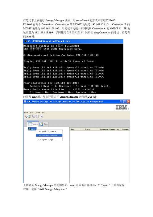
在笔记本上安装好Storage Manager以后,用out-of-band的方式来管理DS3400。
DS3400有两个Controller,Controler A的MGMT地址是192.168.128.101,Controller B的MGMT地址为192.168.128.102,用笔记本连接一根网线到Controller A的MGMT口,IP地址设置为192.168.128.199,子网掩码255.255.255.0,然后去ping Controller的地址,看是否能ping通能正常ping通,现在开始运行Storage Manager来管理DS3400上图就是Storage Manager的初始界面,xulei是本地计算机名,在“xulei”上单击鼠标右键,选择“Add Storage Subsystem”在Controller处,填写DS3400 MGMT的地址,即192.168.128.101,然后点击“Add”(因为现在只连接了一个Controller,所以只填写一个Controller的地址。
如果要把两个Controller的地址都填上去,需要将两个Controller的MGMT口都接在交换机上,和笔记本在一个网络内)然后出现以下提示(DS3400是双控,但当前只连接到其中一个Controller,所以只添加这个Controller即可),选择“Yes”提示添加成功,是否要添加另一个,选择”No”然后在管理主界面就会出现刚发现的DS3400,在Storage Subsystem Unamed上单击鼠标右键,选择”Rename”可以对存储进行改名设置,这里我们将它改名为DS3400然后在主界面,单击鼠标右键,选择”Manage Storage Subsystem”来管理存储,可以配置Array,Logical Driver,Hot Spare,Mapping Host等首先打开的是Summary界面,可以预览此台存储的信息将DS3400的两个Controller都接到交换机之前,我们先把两个Controller的默认IP地址更改一下,点击“TOOLS”然后选择“Configure Ethernet Management Ports”先更改Controller A地址再更改Controller B地址两个Controller的地址更改后,把他们接到交换机上,再把笔记本的IP地址改成10.200 45.32,接到交换机上,然后去ping两个Controller的地址,可以看到刚才的更改已经生效了X3650服务器上装了两块HBA卡,每块卡都通过一根光纤连接到DS3400的一个Controller上的FC Port,现在我们来看DS3400是否能发现服务器,在管理主页点“Congifure”,然后选择Configure Host Access(Manual)输入主机名,和选择系统版本已经发现服务器上的两块HBA卡,把他们添加进去添加好后,点NEXT,然后选择NO此台主机不和其他的主机共享logical drives,然后点击NEXT这是对刚才所添加的主机的预览点击finish后,出现下面提示主机创建成功,并选择NO,不创建另一台主机接下来,在配置主页面,点“Configure”后,选择Create Arrays and logical Drives先来创建Array选中“Arrya”后,点击“NEXT”输入Array名称,选择Manual后点击“NEXT”在RAID LEVEL选择RAID 1,然后选择存储上slot 1- solt 10这10块硬盘做RAID 1,选择Calculate后,可看到计算出来的Array的容量,然后点击finish出现以下提示,Array创建成功。
RDAC 驱动安装手记

RDAC 驱动安装手记1安装环境RDAC for linux red hat AS4 U5版本。
2.6.9-55 内核版本安装的版本是:rdac-LINUX-09.01.B5.78-source.tar安装临时存放的地方是:/tmp安装前,修改/etc/modepro.conf要求将DS3400升级成最新的版本firware ,硬盘升级微码。
2配置/etc/modprob.conf文件alias eth0 tg3alias eth1 tg3alias scsi_hostadapter mptbasealias scsi_hostadapter1 mptscsialias scsi_hostadapter2 mptspialias scsi_hostadapter3 mptsasalias scsi_hostadapter4 mptscsihalias scsi_hostadapter5 qla2xxxalias scsi_hostadapter6 megaraid_sasalias scsi_hostadapter7 ata_piixalias scsi_hostadapter8 qla2400alias usb-controller ehci-hcdalias usb-controller1 uhci-hcdoptions qla2xxx ql2xfailover = 0options scsi_mod max_luns=255下面这一部是安装RDAC以后,自动会添加再做修改。
====================================================================== remove qla2xxx /sbin/modprobe -r --first-time --ignore-remove qla2xxx && { /sbin/modprobe -r --ignore-remove qla2xxx_conf;}### BEGIN MPP Driver Comments ###remove mppUpper if [ `ls -a /proc/mpp | wc -l` -gt 2 ]; then echo -e "Please Unload Physical HBA Driver prior to unloading mppUpper."; else /sbin/modprobe -r --ignore-remove mppUpper; fi# Additional config info can be found in /opt/mpp/modprobe.conf.mppappend.# The Above config info is needed if you want to make mkinitrd manually.# Please read the Readme file that came with MPP driver for building RamDisk manually.# Edit the '/etc/modprobe.conf' file and run 'mppUpdate' to create Ramdisk dynamically.### END MPP Driver Comments ###3配置磁盘柜确保DS3400上的光纤HBA卡上进行了绑定。
- 1、下载文档前请自行甄别文档内容的完整性,平台不提供额外的编辑、内容补充、找答案等附加服务。
- 2、"仅部分预览"的文档,不可在线预览部分如存在完整性等问题,可反馈申请退款(可完整预览的文档不适用该条件!)。
- 3、如文档侵犯您的权益,请联系客服反馈,我们会尽快为您处理(人工客服工作时间:9:00-18:30)。
带内配置DS3400
一.环境
1.主机: x3850(8863),HBA卡(42D0405),RHEL AS4update3
2.盘柜:ds3400单控,4块36G SAS硬盘
3.FC lc-lc线缆
二.目的
通过在服务器上安装storagemanager,实现待那管理ds3400,配置3块硬盘RAID5,一块硬盘的全局热备份
三.配置
1.安装RDAC (参看rdac包中的readme)
1)redhat as4u3
下载地址:/rdac/(随DS3400光盘中有)
解压源码包:tar -zxvf rdac-LINUX-<version>-source.tar.gz
编译及安装:Make
Make install
编译后会在系统/boot目录中生成新的img文件
修改启动配置文件:
/boot/grub/menu.lst
例如:
[注]:2.4内核需要lun号连续
2.6内核对lun号没有要求,可以随机
2)windows:
安装HBA驱动
打系统最新SP
安装Microsoft HotFix KB916048补丁
四.在rehdat as4u3上安装StorageManager
a.在图形环境下,在桌面上右击,选择”open temital” (命令行模式会报找不到java图形类包的错误)
b.改变目录到StorageManager安装文件的目录执行: ./SMIA-LINUX26-<version>.bin
c.语言选择english
d.选择完全安装
e.安装完成后的桌面图标
五.配置阵列:
1.自动搜索盘柜:
2.发现盘柜后,重命名:
3.启动配置工具:
4.查看盘柜初始状态:
5.查看4块为分配的硬盘:
6.选择config选项卡中的”config host access(manual)”
7.添加光纤HBA卡(自动搜索):
8.选择非双机模式:
9.完成添加主机,选择config选项卡中的”create logical drive”:
10.选择手动配置阵列,选中3块盘做一个RAID5,选择”calculate capacity”后继续
11.创建LUN1,大小30G,segment size为128K:
12.映射LUN1到主机中,选择lun为0
13.在”free capacity”中创建lun2:
14.创建LUN2,segment size为256KB:
15.映射LUN2到前面创建的主机上,lun号变为1:
16.创建全局热备份盘:config 选项卡-> Create Hot Spare
17.选择手动配置热备份盘,选中剩下的一块硬盘,点选到右侧的热备份框中
完成配置。
重启服务器,确认所映射的LUN都已识别到。
Fdisk –l
ls -lR /proc/mpp。