自动追频使用说明书
鸿劲超声波HJ-GM智能超声波发生器说明书
第一章概述温馨提示:我们超声波发生器振幅调整最好不要超过50%,否则容易坏模具;更换模具需要关闭电源。
一、上海鸿劲智能发生器简介国内首创PLL锁相环自动追频超声波HJ-GM智能系列是上海鸿劲超声波2015精心打造的又一力作,是中国智能超声的领跑品牌。
它采用高性能防干扰微处理器,实现电子操控化,熔接操控全部的参数经由微电脑进行管理,智能化频率控制系统,免去手动调频之不便,音波过载自动检测,时实跟踪最佳谐振点,振动组温度保持最低点,焊头温度升高跟随的频率变化,机器自动进行调整运行更稳定。
二、超声波焊接原理超声波作用于热塑性的塑料接触面时,会产生每秒几万次的高频振动,这种达到一定振幅的高频振动,通过上焊件把超声能量传送到焊区,由于焊区即两个焊接的交界面处声阻大,因此会产生局部高温。
又由于塑料导热性差,一时还不能及时散发,聚集在焊区,致使两个塑料的接触面迅速熔化,加上一定压力后,使其融合成一体。
当超声波停止作用后,让压力持续几秒钟,使其凝固成型,这样就形成一个坚固的分子链,达到焊接的目的,焊接强度能接近于原材料强度。
超声波塑料焊接的好坏取决于换能器焊头的振幅,所加压力及焊接时间等三个因素,焊接时间和焊头压力是可以调节的,振幅由换能器和变幅。
杆决定。
这三个量相互作用有个适宜值,能量超过适宜值时,塑料的熔解量就大,焊接物易变形;若能量小,则不易焊牢,所加的压力也不能太大。
这个最佳压力是焊接部分的边长与边缘每1mm的最佳压力之积。
三、鸿劲HJ-GM发生器特点1、稳定性高:全数字集成电路,采用美国进口高性能抗干扰处理器,同时减少元器件的数目、简化硬件结构,从而提高系统的可靠性。
2、频率自动跟踪:数字频率合成技术结合数字锁相环频率跟踪的复合控制技术,可以消除温度、静载荷、加工面积、工具磨损等因素漂移常规模拟调节器难以克服的缺点,有利于参数调节,便于通过程序软件的修改,方便地调整控制方案和实现多种新型控制策略。
3、出力强劲:IGBT功率模块的运用加上他激式震荡电路结构,使输出功率是传统自激式电路的1.5倍以上。
六通道超声波发生器使用说明书

六通道超声波发生器使用说明书深圳己道科技有限公司目录1概述 (3)2功能部件 (3)2.1前面板 (3)2.2后面板 (4)3接口、功能及技术指标 (4)3.1环境接口 (4)3.2电气接口 (4)3.3结构尺寸 (6)4功能及技术指标 (6)4.1主要功能 (6)4.2技术指标 (6)5基本操作 (7)5.1显示 (7)5.2操作 (9)5.3开机、关机 (11)5.4外部急停使能 (11)5.5总启动、停止 (12)6使用规范 (12)7异常情况处理 (12)8技术支持 (12)1概述六通道超声波发生器(以下简称发生器)可同时输出6通道同频、不同相的超声波信号,具备自动扫频和频率追踪功能,在不同负载状态下6个换能器同时有效谐振,并且1组3个换能器之间相位可调。
发生器可以独立使用,通过面板元件来设置各项功能和参数。
本文介绍了发生器的功能部件,描述了发生器的使用方法。
2功能部件2.1前面板a.液晶显示器,数字化显示所有状态及参数;b.选择按钮,选中需要设置的参数;c.手轮,配合选择按钮设置参数;d.启动/停止按钮,启动或关闭超声信号输出;e.急停使能开关,使能或禁能外部急停信号;f.RS-485通信插座,连接上位机通信线;g.外控IO插座,连接防爆柜IO插头,内含振子类型选择和急停信号。
2.2后面板a.电源开关,接通或关断发生器总电源;b.电源插座,连接电源线;c.散热风扇1、2,排风口,冷却发生器内部元件;d.超声信号插座,输出A、B、C、D、E、F共六个通道的超声信号;e.超声信号接线柱,也是超声信号输出端,内部与超声信号插座并联,便于连接示波器或U型接线端子,红色接线柱为正极,黑色为负极。
3接口、功能及技术指标3.1环境接口a.供电电源:AC220V,50Hz,3000VA;b.环境温度:0℃-45℃;c.环境湿度:1%-95%,无凝露。
3.2电气接口a.电源插座采用带保险管座的三线品字插座,配2.5方的三芯电源线。
超长待机-LG20使用说明书12.1
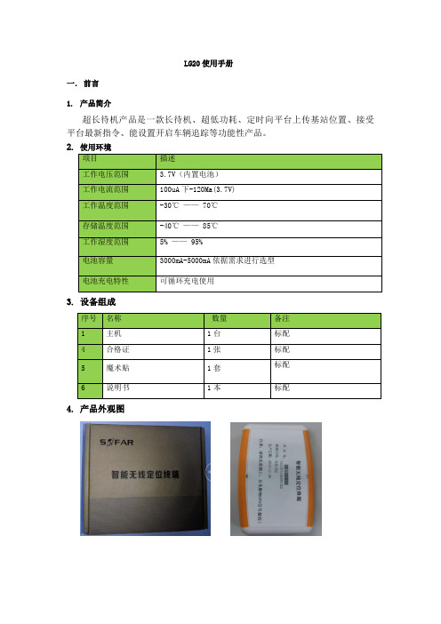
LG20使用手册一. 前言1. 产品简介超长待机产品是一款长待机、超低功耗、定时向平台上传基站位置、接受平台最新指令、能设置开启车辆追踪等功能性产品。
2. 使用环境3. 设备组成4. 产品外观图二.安装说明1.首次安装:LG20首次安装时,先插入SIM卡,再安装上电池;LG20插上电池即开始工作,设备插上电池上电后设备指示灯闪3次,进入连续追踪模式工作,此时若GPS定位,则指示灯常亮,GPS未定位则指示灯常灭,设备工作5分钟之后自动切换到预寻车模式。
在终端全速工作的5分钟时间之内,此时可发短信设置参数,默认不需要再次配置参数即可上线,出厂已设置好默认参数,需要跟监控人员确认是否终端已上线且GPS已定位,GPS定位后会自动校正时间,监控人员确认时间正常,GPS定位并且正常后,安装人员则认为安装完成,若过了5分钟设备还没有上线并定位,设备已进入待机状态,那么需要安装人员需要再次将设备断电再上电,直到监控人员确认设备上线并正常工作了则表明设备安装完成。
2.设备位置放置要求:设备安放时,需水平放置,且标贴面在上;可通过安装盒内的魔术贴贴在终端底面,在车上找合适的位置放置;3.指示灯状态:LG20插上电池即开始工作,上电后指示灯闪动3次,则表明终端正式开始工作4.维护策略:LG20设备电池工作电压低于3.5V时会进行低电压报警,此时应该更换新设备电池或对设备进行充电;电量低时直接更换设备电,通过匹配的线插接电源接口,用5V/1A 的电流对设备进行充电,也可以通过车充转换输出5V/1A对设备进行充电。
三.功能说明1.1终端默认配置LG20默认参数IP:125.91.8.198,端口:12002,APN:CMNET,连接方式:TCP,本机号由程序自动获取SIM卡ICCID号计算而成,终端ID由序列号自动计算而成。
1.2平台工作模式设定LG20工作模式分为3种,包括待机模式、预寻车模式、连续追踪模式,工作模式由平台下发设定,终端默认为预寻车模式。
VC3165 智能频率计使用说明书 第一章 概 述

VC3165智能频率计使用说明书第一章概述(一)概述:VC3165频率计是一种以微处理器为基础而设计的高分辨率、多功能数字式智能化仪器。
具有:频率测量,周期测量以及等精度测量等功能,并有3档功能选择、工作状态显示、单位显示及8位LED高亮度显示。
本仪器是智能数字化仪器,全部功能是用一个单片微控制器(CPU)来完成的。
晶体有恒温控制线路,降低了温度漂移造成的测量误差;输入回路设有衰减器(X1、X20)和AC/DC耦合转换器。
整机性能稳定, 功能齐全,是一种高性能,低价位的理想智能数字化仪器。
本仪器测量频率范围极宽,可从0.01Hz到2.4GHz。
闸门时间从100ms到10s连续可调。
使用本机前请仔细阅读本仪器的资料和操作方法,以便取得最好的使用效果。
(二)技术条件及说明1、测量〈1〉.输入端口本机有两个输入通道端口①.A端口为0.01Hz—50MHz的低频通道端口②.B端口为50MHz—2.4GHz的高频通道端口〈2〉.频率测量①量程第1档: 50MHz— 2.4GHz,由B端口输入第2档: 2MHz—50MHz,由A端口输入第3档: 0.01Hz—2MHz,由A端口输入②分辨率:档位状态频率范围分辨率闸门时间最小闸门时间最大100Hz1GHz—2.4GHz 1kHz 第一档 AC50MHz—1GHz(不含1GHz) 1kHz 10Hz 第二档 AC 2MHz—50MHz 1kHz10Hz0.1HzAC 100Hz—2MHz 10Hz 第三档DC 0.01Hz—100Hz(不含100Hz) 0.001Hz 0.001Hz③闸门时间连续可调:可调范围:100ms—10s④精度:基准时间误差×频率±1个字。
<3>.周期测量:可从A、B两端口中的任何一个端口输入,其中A端口测量范围为 0.2us—10s,B端口测量范围为0.2us—0.5ns。
2.输入特性通道A输入灵敏度:“AC”: ≤80mVrms,“DC”: 0.01Hz—1Hz≤500mVrms,1Hz—100Hz≤80mVrms。
SimplTrack 2 自动跟踪相机快速启动指南说明书

SimplTrack 2 Auto Tracking CameraQuick Start GuideStep 1:The first thing to do when you receive your SimplTrack 2 is read through the included manual.Step 2:As you unbox your HuddleCamHD SimplTrack 2 you will find the camera, a power supply, an IR remote control, the user manual, a 10’ USB 3.0 A-B cable, and a serial control cable used for joystick controllers.Step 3:Now it is time to plug your camera intopower with the included power supply. Let’s put theincluded AAA batteries inside our remote controland take a look at the features. You can pan, tiltand zoom your camera using the up/down/left/rightarrow keys on your remote. You can also, set aspecific PTZ camera preset by clicking the “preset”button and than entering the number you want to set. You can try moving the camera and calling a preset quickly to test out the cameras movement operations.Note: In order to configure the camera, you will need to connect the camera to a live network feed from a network with a DHCP server. Once the camera is turned on and connected to the network we can install the HuddleCamHD SimplTrack control software.Step 4:You can download the HuddleCamHD SimplTrack control software from /ResourcesNote:This software is only available for Windows. Therefore a Windows computer will be required for initial setup of this cameraStep 5:Once the software is installed on your computer, make sure your computer is connected to the same network as the camera. The software should automatically recognize your SimplTrack camera on the network. You can simply double click the camera in your camera list to start configuration.Step 6: You may want to connect your camera to a meeting room computer or in room display. You can connect the camera to a computer using the USB 3.0 output, to any standard televisionusing a DVI to HDMI cable, and to an SDI monitor using a standard SDI cable.Note: The camera features auto resolution & frame rate conversion upon connecting to a video conference software via USB. The camera may auto power cycle in order to reset the camera resolution to match your connected source.Step 7: Let’s review the software interface and configure your SimplTrack. The main interface offers the ability to interact with the basic features of the camera not directly relating toauto-tracking in addition to providing a live preview. Clicking the magnifying glass in the Camera List section will show the available auto tracking cameras on a network. Simply double click on an available camera to connect. Under Lens Control, standard controls are available for Zoom (Tele / Wide), Focus (Near / Far), Iris (Open / Close), and Iris Reset. The Presets section will Set, Call, and Clear Presets 0-255.Note : Preset 1 is used as a reference for framing your tracking subject and Preset 0 is typically used for framing your stage / podium. This is how you tell the camera how much space you want around your subject during the auto-tracking mode.Step 8:The PTZ Controls section serves two functions: first, to provide manual Pan and Tilt controls, the other is to control the OSD using the Menu button. You can start and stop the cameras auto-tracking capabilities at any time using the Start and Stop buttons under Tracking Control. But before we turn on the auto-tracking let’s set some parameters that will ensure seamless operation.Note:Use the “Iris+” button within the OSD to choose options, and “Iris-” to go back a field.Step 9:Let’s click the “Settings” button at the bottom right of this application. When entering the Advanced Parameters settings interface, the live preview will switch to a split-screen showing the images from both the reference camera and the tracking camera. This is where all features relating to auto-tracking can be setup. Under the Basic Settings section, the SDI & DVI Output resolution and frame rate can be set in addition to protocol settings for the RS-232 connection. Clicking Set in the Tracking Zone section will allow you to draw a green rectangle to define a priority tracking area. Within the Tracking Zone you can set Blocking Zones. These are areas that the camera will ignore motion within, such as a doorway with people walking by or an LCD screen with active video content displayed. Note that the Blocking Zones must be used within the Tracking Zone. Tracking Setting will define what actions the camera is allowed to perform. Use Auto-Tilt when your subject will be walking towards and away from the camera. Free track is used to track a ny moving object regardless of being within the defined tracking zone. Use Permanent Track if your presenter walks outside of the defined tracking zone. Enable Auto Zoom to allow the presenter to move freely beyond the Object Lost reference position. AutoZoom is also affected by the Zoom Limit slider.Step 10:Use the Tracking Parameters section to cater the tracking for your room & presenter. Tracking sensitivity defines how much motion is required from the subject to trigger the tracking capabilities. The higher the sensitivity, the less motion is required. Pan & Tilt Speed allows customization over the speed at which the camera tracks. Set the Zoom Limit to define the maximum distance the camera will auto zoom. Set the Lost Timeout to set when the camera will automatically go back to the reference preset after the presenter is lost.Step 11:The Object Lost Action tells the camera to go to Preset 0, Preset 1 or to Stay when the presenter is lost by the camera. For best results, set the Object Lost Action to the full “stage”, which allows the camera to find the presenter and start tracking again.Note:When adjusting the settings of the SimplTrack, be sure to click Save, then OK to save the current settings.Note: W hen working with multiple SimplTrack systems you can ensure you are working on live settings for each camera by clicking the Inquire button to query the connected camera for its current settings. If you have multiple cameras on your network you may want to change the cameras name in the configuration area.Note:To pull the main RTSP stream please use the following URL rtsp://:/main.h264 (example: rtsp://192.168.111.85:5000/main.h264) Note: To pull the sub RTSP stream please use the following URL rtsp://:/sub.h264 (example: rtsp://192.168.111.85:5000/sub.h264)Step 12:You have now set up your SimplTrack and configured the auto-tracking capabilities towork in your environment. Remember if you have any questions during your setup process youcan always call our support team using the phone number listed on our website. You can also submit a support ticket at any time at . Enjoy!。
C2G 无线视频设备操作指南说明书
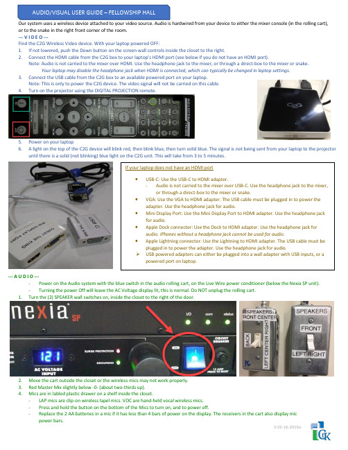
Our system uses a wireless device attached to your video source. Audio is hardwired from your device to either the mixer console (in the rolling cart), or to the snake in the right front corner of the room.--- V I D E O ---Find the C2G Wireless Video device. With your laptop powered OFF:1.If not lowered, push the Down button on the screen wall controls inside the closet to the right.2.Connect the HDMI cable from the C2G box to your laptop’s HDMI port (see below if you do not have an HDMI port).Note: Audio is not carried to the mixer over HDMI. Use the headphone jack to the mixer, or through a direct-box to the mixer or snake.Your laptop may disable the headphone jack when HDMI is connected, which can typically be changed in laptop settings.3.Connect the USB cable from the C2G box to an available powered port on your laptop.Note: This is only to power the C2G device. The video signal will not be carried on this cable.4.Turn on the projector using the DIGITAL PROJECTION remote.5.Power on your laptop6. A light on the top of the C2G device will blink red, then blink blue, then turn solid blue. The signal is not being sent from your laptop to the projectoruntil there is a solid (not blinking) blue light on the C2G unit. This will take from 3 to 5 minutes.--- A U D I O ----Power on the Audio system with the blue switch in the audio rolling cart, on the Live Wire power conditioner (below the Nexia SP unit).-Turning the power Off will leave the AC Voltage display lit, this is normal. Do NOT unplug the rolling cart.1.Turn the (2) SPEAKER wall switches on, inside the closet to the right of the door.2.Move the cart outside the closet or the wireless mics may not work properly.3.Red Master Mix slightly below -0- (about two-thirds up).4.Mics are in labled plastic drawer on a shelf inside the closet.-LAP mics are clip-on wireless lapel mics. VOC are hand-held vocal wireless mics.-Press and hold the button on the bottom of the Mics to turn on, and to power off.-Replace the 2 AA batteries in a mic if it has less than 4 bars of power on the display. The receivers in the cart also display mic power bars.V.02-16-2019a。
调节频率驱动AP03902004E的使用说明说明书
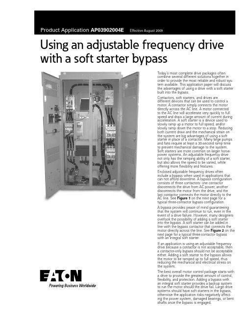
Using an adjustable frequency drive with a soft starter bypassToday’s most complete drive packages oftencombine several different solutions together inorder to provide the most reliable and robust sys-tem available. This application paper will discussthe advantages of using a drive with a soft starterbuilt into the bypass.Contactors, soft starters, and drives aredifferent devices that can be used to control amotor. A contactor simply connects the motordirectly across the AC line. A motor connectedto the AC line will accelerate very quickly to fullspeed and draw a large amount of current duringacceleration. A soft starter is a device used toslowly ramp up a motor to full speed, and/orslowly ramp down the motor to a stop. Reducingboth current draw and the mechanical strain onthe system are big advantages of using a softstarter in place of a contactor. Many large pumpsand fans require at least a 30-second ramp timeto prevent mechanical damage to the system.Soft starters are more common on larger horse-power systems. An adjustable frequency drivenot only has the ramping ability of a soft starter,but also allows the speed to be varied, whileoffering more flexibility and features.Enclosed adjustable frequency drives ofteninclude a bypass when used in applications thatcan not afford downtime. A bypass configurationconsists of three contactors: one contactordisconnects the drive from AC power, anotherdisconnects the motor from the drive, and thelast contactor connects the motor directly to theAC line. See Figure 1 on the next page for atypical three-contactor bypass configuration.A bypass provides peace of mind guaranteeingthat the system will continue to run, even in theevent of a drive failure. However, many designersoverlook the possibility of adding a soft starterinto the bypass. A soft starter can be added inline with the bypass contactor that connects themotor directly across the line. See Figure 2 on thenext page for a typical three-contactor bypasswith an integral soft starter.If an application is using an adjustable frequencydrive because a contactor is not acceptable, thena contactor-only bypass should not be acceptableeither. Adding a soft starter to the bypass allowsthe motor to be ramped up to full speed, thusreducing the mechanical and electrical stress onthe system.The best overall motor control package starts witha drive to provide the greatest amount of control,flexibility, and protection. Adding a bypass withan integral soft starter provides a backup systemto run the motor should the drive fail. Large drivesystems should have soft starters in the bypass,otherwise the application risks negatively affect-ing the power system, damaged bearings, or bentshafts once the bypass is engaged.Eaton Corporation Electrical Sector 1111 Superior Ave.Cleveland, OH 44114United States877-ETN-CARE (877-386-2273)© 2009 Eaton Corporation All Rights Reserved Printed in USAPublication No. AP03902004E / Z9003August 2009PowerChain Management is a registered trademark of Eaton Corporation. All other trademarks are property of theirrespective owners.Product Application AP03902004EEffective August 2009Using an adjustable frequency drivewith a soft starter bypassFigure 1. Typical Three-Contactor Bypass ConfigurationFigure 2. Typical Three-Contactor Bypass with Integral Soft Starter。
超声波塑焊机(自动追频)安全操作指导书
超声波塑焊机(自动追频)安全操作指导书 版本/版次:A/2
页 次:1/2 1.目的:使设备操作规范化,避免安全事故发生 2.适用范围:公司自动追频超声波焊接机 3.职责:设备使用部门的设备操作员负责超声波塑焊机的日常使用 4.操作程序
4.1 开机 4.1.1 接通进超声波电源开关(长时间不使用超声波焊接机时会关闭此开关); 4.1.2 打开压缩空气阀门,把在侧面总气压阀压力调至约 3kg; 4.1.3 把机器上的红色急停开关拔起,按下机箱上的电源开关(POWER)键,同时电源指示灯亮, 此时机器进入开机自检,约十秒钟后机器进入待机工作状态,机器按键是自锁状态不能修改参数 (如图 1 示); 4.1.4 按下机箱面板上的 PIN 键后屏上会出现提示菜单,并在光标处输入密码 1000,按键锁即可 打开,此时出现主菜单(Adjust ment 手动调试状态,Weld parameters 焊接参数设定,Limits 限 制参数设定,Information 资料,Database 数据库,System parameter 系统参数设定)(如图 1 示); 4.1.5 将光标移动到 Adjust ment 后,按下 Enter 键确认后,双手按下左右启动按钮焊头下降并 手动调整模具的位置(如图 2 示); 4.1.6 将光标移动到 Weld parameters 后,按下 Enter 键确认后,进入模式设定窗口并根据工艺 要求选择适当的工作模式,模式选定试验好即可生产作业; 4.1.7 如在生产过程中出现任何事故请及时按设备工作台上的急停开关(红色按钮)(如图 1 示)。 注:冶具安装要由专责人员负责安装调试
5.参考资料:《超声波焊接机使用说明书》 6.所用表格:《超声波塑焊机设备日常检查表》
- 1、下载文档前请自行甄别文档内容的完整性,平台不提供额外的编辑、内容补充、找答案等附加服务。
- 2、"仅部分预览"的文档,不可在线预览部分如存在完整性等问题,可反馈申请退款(可完整预览的文档不适用该条件!)。
- 3、如文档侵犯您的权益,请联系客服反馈,我们会尽快为您处理(人工客服工作时间:9:00-18:30)。
UK系列自动追频超声波焊接机模糊程序—智能控制功率器件—IGBT电路控制—DSP锁相跟踪—DDS模块结构—维护便利频率动态扫描—稳定、低故障功率大小数字化设定—易掌控方形立柱—减少机头后仰机头燕尾槽设计—精密Please refer to the manual in detail before installing, operating and debugging.安装,操作或调试设备前,请先详细阅读本说明一、自动追频超声波焊接机技术简介超声波焊接是塑料制品的速熔接技术,各种可塑性塑胶件均可使用超声波熔接处理,而不需加溶剂、粘接剂或其他辅助品。
其优点是简单、快速、生产效率高、低成本,焊接质量好。
超声波塑胶焊接原理是由POWER 发生器产生和超声波换能器相同谐振频率的高压、高频能量,通过换能系统,把电功率转换为高频机械振动,使加于塑料制品工件上,通过工件表面及内在分子间的磨擦而使融接接口的温度升高,当温度达到此工件本身的熔点时,工作接口迅速溶化,继而填充于接口间的空隙,当震动停止,工件同时在一定的压力下冷却定形成完美的焊接。
该机型采用了IGBT、DSP、DDS 和模糊程序软件控制技术,使该产品实现了全数字化设定和智能控制。
其外型美观、结构简洁、使用简单、节能高效。
适用于可塑性塑料制品的焊接、铆接、点焊以及金属件与塑料件间的镶嵌和压边工艺。
对焊接较软的PE、PP 材料,以及直径超大,长度超长的塑料焊件,有其独特优势,能满足各种产品的需要,能为用户提高生产效率、提高产品质量以及产品档次做贡献。
产品使用范围:1、塑料玩具、水枪、水族类游戏机、儿童玩具、塑制礼品等;2、电子产品:录音、录音带盒及芯轮、磁盘外壳、手机电池板及整流变压器、开关插座、遥控器、电子蚊拍、仿伪瓶盖等。
3、家用电器:电子钟、电吹鼓手风筒、蒸汽熨斗水箱、电热壶气襄、计算机等。
4、文具日用品:文具盒、水族格尺、文件夹中缝及外壳、笔座、化妆品盒壳、牙膏管封尾、化妆镜、保温杯、打火机、调味瓶等密封容器。
5、汽车、摩托车:蓄电池、前角灯、后车灯、仪表、反射器等。
我们可以为用户提供各种频率的超声波塑料焊接机和服务,包括维修、提供配件,为用户设计制作各种焊接模具等。
二、设备使用UK 系列自动追频超声波塑料焊接机电源有四种工作模式,即正常工作模式、设置模式、换能器变幅杆模具检测模式和连续运行测试模式。
A.换能器、变幅杆、模具检测模式换能器、变幅杆、模具检测模式在使用之前需要对换能器变幅杆和模具进行检测。
在换能器变幅杆模具检测模式下,可以设定工作频率范围和自动测试设置最佳参数。
设置方式如下:1.同时按住SELEC 和▲键,开电源开关,面板上的“延时”DT 和“焊接”ST灯同时出现闪烁时,即进入换能器、变幅杆、模具检测模式。
2.按SELEC 键,使面板上的“延时”DT 和“保压”MT 灯出现闪烁时,即可以设定换能器的最高工作频点,15KHz 的换能器最高频率点一般设15.00KHz (最高设定值不要超过15.50 KHz)。
3.按SELEC 键,使面板上的“延时”DT 和“频率”F 灯出现闪烁时,即可以设定最低频率点。
15KHz 的换能器最低频率点一般设定在14.30 KHz (最低设定值不要低于14.20KHz)。
4.按SELEC 键,使面板上的“延时”DT 和“记数”T 灯出现闪烁时,即可以设定加压保护电流值。
一般设定在100%(即显示100)。
设定在100%时保护点是正常工作电流的150%,设定在50%时保护点是正常工作电流的70%。
5.按SELEC 键,面板上的“延时”DT 和“功率”P 灯出现闪烁时没有使用,不用管他。
6.按SELEC 键,使面板上的“延时”DT 和“焊接”ST 灯同时出现闪烁时,即进入换能器变幅杆模具检测模式,按ENTER 键,机箱将会自动测试换能器变幅杆和模具的频率参数和工作状态,测试完毕机箱上显示的频率即是换能器变幅杆和模具的工作频率,并自动存储。
注意:1)如果测试完毕机箱上显示的频率是在14.50~14.80 KHz 之间,说明换能器变幅杆和模具完好正常,可以正常使用。
2)如果测试完毕机箱上显示的频率是小于14.50 KHz 或大于14.80 KHz,则一般说明模具的加工有问题,需要修模具,使测试的频率在14.50~14.80 KHz 之间。
当然,如果换能器变幅杆和模具是已经使用了比较长的时间,测试的频率会超出14.50~14.80 KHz 之间,但不能低于14.20KHz 或高于14.90 KHz,否则说明模具和换能器不匹配,换能器的出力会降低很多,换能器也会发热而缩短使用寿命。
3)如果测试完毕,机箱上显示的频率是最高设定频点,并发出“嘀,嘀,嘀,嘀┄┄”的叫声,则说明换能器、变幅杆或模具有问题,需要检查或更换换能器或模具。
7.设定完毕关闭电源即可进入其它的工作模式。
B.调节模式在调节模式下,可以对超声波塑料焊接机的加压时间(DT)、焊接时间(ST)、保压时间(MT)和功率(P)进行独立的设置设置。
频率(F)一般不需要人工设置。
工作参数设置模式方式如下:1.打开电源开关,按SELEC 键,使面板上的“记数”T 灯出现亮时,再同时按住▲和▼键,使“记数”T 灯出现闪烁时即进入调节模式。
2.按SELEC 键,使加压时间(DT) 灯出现闪烁时,即可设置加压时间。
按▲或▼键,选择合适的时间(可以在0.1~999S 内选取),一般选择1S,按动ENTER键,模具即向下运行,再按动ENTER 键,模具即向上运行。
模具上下运行的时间相同。
3.按SELEC 键,使面板上的焊接(ST) 灯出现闪烁时,即可设置焊接时间。
按▲或▼键,选择合适的焊接时间(可以在0.1~999S 内选取),一般选择0.1~3S,按动ENTER 键,主机即按照设定的焊接时间向换能器发波。
如果模具是加压状态,则发波功率是按照面板设定的功率发波,如果模具是未加压状态,则发波功率是按照最小的功率发波。
4.按SELEC 键,使面板上的保压时间(MT) 灯出现闪烁时,即可设置保压时间。
按▲或▼键,选择合适的保压时间(可以在0.1~999S 内选取),一般选择1~10S,按动ENTER 键,主机即按照设定的保压时间倒记时(机头不动作)。
5.按SELEC 键,使面板上的工作频率(F) 灯出现闪烁时,即可看发波频率。
这个参数一般不要调节。
在这个模式下为了提高频率的显示精度,四位显示的是频率的个位到千位,没有显示十千位。
所以,看到的数字请在数字的前面加1 即是实际频率。
如:看到的是4688,则实际频率值是14688Hz。
6.按SELEC 键,使面板上的记数(T) 灯出现闪烁时,按动ENTER 键,即可清除焊接次数。
7.按SELEC 键,使面板上的功率调节(P) 灯出现闪烁时,即可设置焊接功率。
将欲焊接的工件放置在模具上并在加压状态下,按动ENTER 键,主机将按照设定的焊接时间向换能器发波。
如焊接功率不适合,可调节▲或▼键。
数值可在300~2000 之间设定。
电流指示,每个灯约代表1A 的电流值。
8.所有参数设置完毕将自动存储。
如果关闭电源再打开电源,主机将自动进入正常工作模式。
也可以按SELEC 键,使面板上的记数(T) 灯出现闪烁时,再同时按住▲和▼键,使“记数”T 灯出现长亮时即进入正常工模式。
C.老化测试模式(新出厂设备已经过老化测试,更换新的换能器或变幅杆后必须进行老化测试)在设置模式 B 下,按选择键SELEC,使面板上的功率(P) 灯出现闪烁。
先按住▼,再按ENTER 键,ST,MT,P 灯同时出现闪烁,主机即进入连续运行测试模式。
按▲或▼键,选择要自动测试的次数。
按主机面板上的ENTER 键,主机就会按照设置模式下设定的延时(DT)、焊接(ST)、保压(MT)和复位(同DT)的时间自动的循环工作,直到设置的测试次数为零才停止。
也可以关闭电源开关终止测试。
老化测试模式主要用于检测焊接设备的可靠性和稳定性。
注意:1.在进入老化测试模式前,请先设置好发波时间和保压时间。
发波时间决定每次测试的发波时间,保压时间决定每次发波的间隔时间;2.在进入老化测试模式前,请先设置好输出功率。
每次发波的功率将按照设定的功率发波;3.在进入老化测试模式前,请先选择好是加压状态还是不加压状态,如果是在加压状态下,则老化测试模式每次发波的功率是按照设置好的输出功率发波。
如果是在不加压状态下,则老化测试模式每次发波的功率是按照最小的输出功率发波。
4.在加压状态下发波,可用一块木头代替工件来测试。
D.正常工作模式在设备正确安装完毕,并已经设定好上述的参数。
开启电源开关,电箱将会自动的将模具置在上的位置。
按动主机面板上的ENTER 键或按操控台的启动按钮,主机就会按照设置模式下设定的延时(DT)、焊接(ST)、保压(MT)和复位(同DT)时间,按照程序顺序工作。
一个工作周期完成后主机会自动记数一次。
按选择键SELEC,可以随时设置和调节加压时间(DT)、焊接时间(ST)、保压时间(MT)和功率(P)。
频率(F)一般不需要人工设置,可以观察换能器变幅杆和模具的工作频率。
选择到相应的位置可以按▲或▼键调节。
三、主要技术指标型号:UK2000,UK3000,输出功率:2000W,3000W频率:15KHZ或20KHZ电源电压:(单相)AC220V焊头行程:75mm或100mm控制系统:频率自动追踪,模具、换能器自动检测;气压:气压范围:1-7bar压缩机:1HP外形尺寸:L725mm*W400mm*H1200mm四、注意事项1.超声波设备为高压设备,无专业知识人员请勿打开机箱维护设备!2. 超声波换能器的高压端的工作电压约为600~1200V,发波时人严禁接触高压端的任何部位,否则有电击和烧伤的危险!3. 电箱功率输出和超声波换能器的连接线不能接反,否则机箱将带高压电!4. 超声波换能器的高压端和地勿长时间短路,否则容易损坏主机;5. 主机内的风扇、变压器等每6 个月用刷子清除其表面的灰尘,环境恶劣的每6 个月清除其表面的灰尘。
6. 第一次焊接,电箱会用2S 的时间自己学习一次,以后电箱会按照设定的程序工作。
7. 在焊接的过程中,工作频率如果出现越来越低,说明模具的温度过高了。
8. 在焊接的过程中,如果出现频率到了最高或最低设定值,并发出“嘀,嘀,嘀,嘀┄┄”的叫声,则说明换能器、变幅杆或模具有问题,需要检查或更换。
五、技术支持1.接合部的接合形状1.1 斜面接合该接合是利用斜面以达到完全的面接合。
由于可获得均匀的热能及较大的焊接面积,故焊接强度高,气密性好。
设计时的注意事项:1)接合部的倾斜角度越大则焊接面积也就越大,但由于结合面不易产生滑动,故需要较大的能源。