931BS-470M中文资料
迪赛拜金属电压分辨率领导电阻说明书
MBB0207VD1501BC100MBB0207VE1002BC100MBA/SMA 0204, MBB/SMA 0207, MBE/SMA 0414 - PrecisionVishay BeyschlagPrecision Metal Film Leaded ResistorsLINKS TO ADDITIONAL RESOURCESDESCRIPTIONMBA/SMA 0204, MBB/SMA 0207, and MBE/SMA 0414 precision leaded thin film resistors combine the proven reliability of the professional products with an advanced level of precision and stability. Therefore they are perfectly suited for applications in the fields of test and measuring equipment along with industrial and medical electronics.FEATURES•IECQ-CECC approved according to EN 140101-806•Superior overall stability: class 0.05•Wide precision ohmic range: 10 Ω to 1.5 M Ω•Radial version available for MBB/SMA 0207•Material categorization: for definitions of compliance please see /doc?99912APPLICATIONS•Test and measuring equipment •Industrial electronics•Medical electronicsNotes•MB_ series has been merged with the related SMA series to form one series “MB_/SMA__”(1)Please refer to APPLICATION INFORMATION below3D 3D3D ModelsTECHNICAL SPECIFICATIONSDESCRIPTION MBA/SMA 0204MBB/SMA 0207MBE/SMA 0414DIN size 020*********CECC size AB DResistance range 22 Ω to 332 k Ω10 Ω to 1 M Ω22 Ω to 1.5 M ΩResistance tolerance ± 0.25 %; ± 0.1 %Temperature coefficient ± 25 ppm/K; ± 15 ppm/KRated dissipation, P 700.25 W 0.40 W 0.65 W Operating voltage, U max. AC RMS /DC 200 V 350 V 500 V Operating temperature range (1)-55 °C to +125 °CPermissible film temperature, ϑF max. (1)125 °CPermissible voltage against ambient (insulation):1 min; U ins 300 V 500 V 800 V Continuous75 V75 V 75 VFailure rate: FIT observed≤ 0.1 x 10⁻⁹/hMBA/SMA 0204, MBB/SMA 0207, MBE/SMA 0414 - PrecisionVishay BeyschlagAPPLICATION INFORMATIONThe power dissipation on the resistor generates a temperature rise against the local ambient, depending on the heat flow support of the printed-circuit board (thermal resistance). The rated dissipation applies only if the permitted film temperature is not exceeded. Furthermore, a high level of ambient temperature or of power dissipation may raise the temperature of the solder joint, hence special solder alloys or board materials may be required to maintain the reliability of the assembly.These resistors do not feature a limited lifetime when operated within the permissible limits. However, resistance value drift increasing over operating time may result in exceeding a limit acceptable to the specific application, thereby establishing a functional lifetime. The designer may estimate the performance of the particular resistor application or set certain load and temperature limits in order to maintain a desired stability.Note•The presented operation modes do not refer to different types of resistors, but actually show examples of different loads, that lead to different film temperatures and different achievable load-life stability (drift) of the resistance value. A suitable low thermal resistance of the circuit board assembly must be safeguarded in order to maintain the film temperature of the resistors within the specified limitsNotes•Radial version (RB, UB) cannot be qualified according to CECC so these can only be ordered with variant N or S (1)Approval is according to EN 140101-806, version A, or the approved IECQ-CECC resistance range, please refer to: /doc?28945MAXIMUM RESISTANCE CHANGE AT RATED DISSIPATIONOperation mode PrecisionStandardClimatic category-10 °C / +85 °C / 56 days-55 °C / +125 °C / 56 daysRated dissipation, P 70MBA/SMA 02040.07 W 0.25 W MBB/SMA 02070.11 W 0.40 W MBE/SMA 04140.17 W 0.65 W Permissible film temperature, ϑF max.85 °C 125 °C Max. resistance change at rated dissipation |ΔR /R max.|, after:MBA/SMA 0204100 Ω to 100 k Ω100 Ω to 100 k Ω1000 h ≤ 0.05 %≤ 0.25 %8000 h ≤ 0.1 %≤ 0.5 %225 000 h ≤ 0.3 %≤ 1.5 %MBB/SMA 0207100 Ω to 270 k Ω100 Ω to 270 k Ω1000 h ≤ 0.03 %≤ 0.15 %8000 h ≤ 0.1 %≤ 0.5 %225 000 h ≤ 0.3 %≤ 1.5 %MBE/SMA 0414100 Ω to 470 k Ω100 Ω to 470 k Ω1000 h ≤ 0.05 %≤ 0.2 %8000 h ≤ 0.1 %≤ 0.4 %225 000 h ≤ 0.3 %≤ 1.2 %TEMPERATURE COEFFICIENT AND RESISTANCE RANGE (1)TYPE / SIZETCR TOLERANCE RESISTANCE (2)E-SERIESMBA/SMA 0204± 25 ppm/K± 0.25 % 22 Ω to 332 k ΩE96; E192± 0.1 %43 Ω to 332 k Ω± 15 ppm/K ± 0.25 %22 Ω to 221 k Ω± 0.1 %43 Ω to 221 k ΩMBB/SMA 0207± 25 ppm/K± 0.25 %10 Ω to 1 M Ω± 0.1 %10 Ω to 1 M Ω± 15 ppm/K ± 0.25 %10 Ω to 1 M Ω± 0.1 %10 Ω to 1 M ΩMBE/SMA 0414± 25 ppm/K± 0.25 %22 Ω to 1.5 M Ω± 0.1 %43 Ω to 1 M Ω± 15 ppm/K± 0.25 %22 Ω to 1 M Ω± 0.1 %43 Ω to 1 M ΩMBA/SMA 0204, MBB/SMA 0207, MBE/SMA 0414 - PrecisionVishay BeyschlagNote•For details related to packaging specs, refer datasheet link /doc?28721Note•The products can be ordered using either the PRODUCT DESCRIPTION or the PART NUMBERPACKAGINGTYPE / SIZE CODE QUANTITY PACKAGING STYLE WIDTH PITCH PACKAGING DIMENSIONS MBA/SMA 0204C11000Taped acc. to IEC 60286-1fan-folded in a box 53 mm5 mm184 mm x 75 mm x 42 mmCT 5000330 mm x 75 mm x 55 mm MBB/SMA 0207C11000Taped acc. to IEC 60286-1fan-folded in a box 53 mm5 mm184 mm x 74 mm x 42 mmCT 5000 324 mm x 77 mm x 82 mmMBB/SMA 0207 UB = 2.5 mm pitchN44000Taped acc. to IEC 60286-2fan-folded in a box -12.7 mm330 mm x 262 mm x 45 mm R44000Taped acc. to IEC 60286-2on a reel -330 mm x 253 mm x 48 mmMBB/SMA 0207 RB = 5.0 mm pitchN44000Taped acc. to IEC 60286-2fan-folded in a box -330 mm x 262 mm x 45 mmR44000Taped acc. to IEC 60286-2on a reel -330 mm x 253 mm x 48 mmMBE/SMA 0414C11000Taped acc. to IEC 60286-1fan-folded in a box63 mm 5 mm 374 mm x 84 mm x 47 mmPART NUMBER AND PRODUCT DESCRIPTION - CECC APPROVED PRODUCTSPart Number: MBB0207VD1001BCT00TYPE / SIZEVERSION TCRRESISTANCE TOLERANCE PACKAGINGSPECIALMBA0204 =MBA/SMA 0204MBB0207 =MBB/SMA 0207MBE0414 =MBE/SMA 0414V = CECC 06N = RB radial 5 mm for MBB/SMA 0207S = UB radial 2.5 mm for MBB/SMA 0207E = ± 15 ppm/K D = ± 25 ppm/K3 digit value 1 digit multiplier MULTIPLIER B = ± 0.1 %C = ± 0.25 %CT C1N4R400 = standard L0 = welding joint not lacquered for MBB/SMA 0207KL = lacquered welding joint for MBA/SMA 02049 = *10-1 0 = *100 1 = *1012 = *1023 = *1034 = *104Product Description: MBB/SMA 0207-25 0.1 % CECC 06 CT 1K0MBB/SMA 0207-250.1 %CECC 06CT 1K0TYPE / SIZE TCR TOLERANCE VERSION PACKAGINGRESISTANCE MBA/SMA 0204MBB/SMA 0207MBE/SMA 0414± 15 ppm/K ± 25 ppm/K± 0.1 %± 0.25 %CECC 06CECC 06 L0CECC 06 KLCT C1N4R41K0 = 1 k Ω51R1 = 51.1 ΩB 2V D 10BC T 0BM 701000MBA/SMA 0204, MBB/SMA 0207, MBE/SMA 0414 - Precision Vishay BeyschlagDESCRIPTIONProduction is strictly controlled and follows an extensive set of instructions established for reproducibility. A homogeneous film of metal alloy is deposited on a high grade ceramic body and conditioned to achieve the desired temperature coefficient. Plated steel termination caps are firmly pressed on the metallized rods. A special laser is used to achieve the target value by smoothly cutting a helical groove in the resistive layer without damaging the ceramics. Connecting wires of electrolytic copper plated with 100 % pure matte tin are welded to the termination caps. The resistor elements are covered by a light blue protective coating designed for electrical, mechanical and climatic protection. F our or five color code rings designate the resistance value and tolerance in accordance with IEC 60062.The result of the determined production is verified by an extensive testing procedure performed on 100 % of the individual resistors. Only accepted products are stuck directly on the adhesive tapes in accordance with IEC 60286-1 or for the radial versions in accordance with IEC 60286-2.MATERIALSVishay acknowledges the following systems for the regulation of hazardous substances:•IEC 62474, Material Declaration for Products of and for the Electrotechnical Industry, with the list of declarable substances given therein (1)•The Global Automotive Declarable Substance List (GADSL) (2)•The REACH regulation (1907/2006/EC) and the related list of substances with very high concern (SVHC) (3) for its supply chainThe products do not contain any of the banned substances as per IEC 62474, GADSL, or the SVHC list, see /how/leadfree.Hence the products fully comply with the following directives:•2000/53/EC End-of-Life Vehicle Directive (ELV) and Annex II (ELV II)•2011/65/EU Restriction of the Use of Hazardous Substances Directive (RoHS) with amendment 2015/863/EU•2012/19/EU Waste Electrical and Electronic Equipment Directive (WEEE)Vishay pursues the elimination of conflict minerals from its supply chain, see the Conflict Minerals Policy at /doc?49037.ASSEMBLYThe resistors are suitable for processing on automatic insertion equipment and cutting and bending machines. Excellent solderability is proven, even after extended storage. They are suitable for automatic soldering using wave or dipping.The resistors are completely lead (Pb)-free, the pure matte tin plating provides compatibility with lead (Pb)-free and lead-containing soldering processes. The immunity of the plating against tin whisker growth, in compliance with IEC 60068-2-82, has been proven under extensive testing. The encapsulant is resistant to cleaning solvent specified in IEC 60115-1(3). The suitability of conformal coatings, if applied, shall be qualified by appropriate means to ensure the long-term stability of the whole system.All products comply with GADSL (1) and the IEC 62474 (2) list of legal restrictions on hazardous substances. This includes full compliance with the following directives:•2000/53/EC End of Vehicle Life Directive (ELV) and Annex II (ELVII)•2011/65/EU Restriction of the use of Hazardous Substances Directive (RoHS)•2002/96/EC Waste Electrical and Electrical Equipment Directive (WEEE)APPROVALSThe resistors (CECC version) are approved within the IECQ-CECC Quality Assessment System for Electronic Components to the detail specification EN 140101-806 which refers to EN 60115-1 and EN 60115-2 and the variety of environmental test procedures of the IEC 60068 series. Conformity is attested by the use of the CECC logo () as the Mark of Conformity on the package label for the CECC version.Vishay Beyschlag has achieved “Approval of Manufacturer” in accordance with IECQ 03-3-1, clause 2. The release certificate for “Technology Approval Schedule” in accordance with CECC 240001 based on IECQ 03-3-1, clause 6 is granted for the Vishay Beyschlag manufacturing process.RELATED PRODUCTSF or a corelated range of professional TCR and tolerance specifications see the datasheet:•“Professional Thin F ilm Leaded Resistors”, /doc?28766For products approved to EN 140101-806, version E, with established reliability and failure rate level E7 (Quality factor πQ = 0.1), see the datasheet: •“Established Reliability Thin F ilm Leaded Resistors”, /doc?28768Notes(1)Global Automotive Declarable Substance List, see (2)CEF IC (European Chemical Industry Council), EECA (European Electronic Component Manufacturers Association), EICTA (Europeantrade organization representing the information and communications technology and consumer electronics), see /SearchResults.aspx?Search=eicta.All products comply with the IEC 62474, Material Declaration for Products of and for the Electrotechnical Industry(3)Other cleaning solvents with aggressive chemicals should be evaluated in actual cleaning process for their suitabilityMBA/SMA 0204, MBB/SMA 0207, MBE/SMA 0414 - PrecisionVishay BeyschlagFUNCTIONAL PERFORMANCEDeratingRise of the surface temperature.Temperature RiseCurrent Noise A 1 in accordance with IEC 60195Ambient Temperature in °CP o w e r i n %2004060801000W40K 600.2200.10.30.40.50.60.70.8Load PT e m p e r a t u r e R i s e T r0.010.11100:µV/V1K10K 100K 1M 10M Resistance Value RC u r r e n t N o i s e A 1MBA/SMA 0204, MBB/SMA 0207, MBE/SMA 0414 - Precision Vishay Beyschlag TEST PROCEDURES AND REQUIREMENTSAll tests are carried out in accordance with the following specifications:•IEC 60115-1, generic specification•IEC 60115-2, sectional specification•EN 140101-806, detail specification•IEC 60068-2-xx, test methodsThe components are approved under the IECQ-CECC quality assessment system for electronic components. The parameters stated in the Test Procedures and Requirements table are based on the required tests and permitted limits of EN 140101-806. The table presents only the most important tests, for the full test schedule refer to the documents listed above. However, some additional tests and a number of improvements against those minimum requirements have been included. The testing also covers most of the requirements specified by EIA/ECA-703 and JIS-C-5201-1. The tests are carried out under standard atmospheric conditions in accordance with IEC 60068-1, 4.3, whereupon the following values are applied:•Temperature: 15 °C to 35 °C•Relative humidity: 25 % to 75 %•Air pressure: 86 kPa to 106 kPa (860 mbar to 1060 mbar) A climatic category LCT / UCT / 56 is applied, defined by the lower category temperature (LCT), the upper category temperature (UCT), and the duration of exposure in the damp heat, steady state test (56 days). The components are mounted for testing on printed circuit boards in accordance with IEC 60115-1, 5.5, unless otherwise specified.TEST PROCEDURES AND REQUIREMENTSIEC 60115-1 CLAUSE(3)IEC60068-2TESTMETHOD(3)TESTPROCEDUREREQUIREMENTS PERMISSIBLE CHANGE(ΔR max.)Stability for product types:STABILITYCLASS 0.05STABILITYCLASS 0.1STABILITYCLASS 0.25MBA/SMA 0204100 Ω to 100 kΩ43 Ω to 221 kΩ22 Ω to 332 kΩMBB/SMA 0207100 Ω to 270 kΩ43 Ω to 510 kΩ10 Ω to 1 MΩMBE/SMA 0414100 Ω to 470 kΩ43 Ω to 1 MΩ22 Ω to 1.5 MΩ6.1-Resistance-± 0.25 %; ± 0.1 % 12.2-Voltage proof U RMS = U ins; 60 s No flashover or breakdown6.2-TemperaturecoefficientAt 20/LCT/20 °C and20/UCT/20 °C± 25 ppm/K; ± 15 ppm/K8.1-Short timeoverloadRoom temperature;U = 2.5 x orU = 2 x U max.; 5 s± (0.01 % R + 0.01 Ω)no visible damage± (0.02 % R + 0.01 Ω)no visible damage± (0.05 % R + 0.01 Ω)no visible damage9.521 (Ua1)21 (Ub)21 (Uc)Robustness ofterminationsTensile, bending and torsion± (0.01 % R + 0.01 Ω)± (0.02 % R + 0.01 Ω)± (0.05 % R + 0.01 Ω)11.120 (Ta)Solderability+235 °C; 2 ssolder bath method;SnPb40Good tinning (≥ 95 % covered, no visible damage) +245 °C; 3 ssolder bath method;SnAg3Cu0.511.220 (Tb)Resistance tosoldering heatUnmounted components;(270 ± 3) °C;(10 ± 1) s± (0.01 % R + 0.01 Ω)no visible damage± (0.02 % R + 0.01 Ω)no visible damage± (0.05 % R + 0.01 Ω)no visible damage10.114 (Na)Rapidchange oftemperature30 min at LCT = -55 °C30 min at UCT = 125 °C5 cycles± (0.01 % R + 0.01 Ω)no visible damage± (0.02 % R + 0.01 Ω)no visible damage± (0.05 % R + 0.01 Ω)no visible damage MBA/SMA 0204: 500 cyclesMBB/SMA 0207: 200 cyclesMBE/SMA 0414: 100 cycles± (0.25 % R + 0.05 Ω)no visible damage± (0.25 % R + 0.05 Ω)no visible damage± (0.25 % R + 0.05 Ω)no visible damage9.11 6 (Fc)Vibration 10 sweep cycles per direction;10 Hz to 2000 Hz1.5 mm or 200 m/s2± (0.01 % R + 0.01 Ω)± (0.02 % R + 0.01 Ω)± (0.05 % R + 0.01 Ω) P70 x RMBA/SMA 0204, MBB/SMA 0207, MBE/SMA 0414 - PrecisionVishay BeyschlagNotes(1)± (0.03 % R + 0.01 Ω) for MBB/SMA 0207(2)± (0.15 % R + 0.05 Ω) for MBB/SMA 0207(3)The quoted IEC standards are also released as EN standards with the same number and identical contents10.3Climatic sequence:± (0.05 % R + 0.01 Ω)no visible damage ± (0.1 % R + 0.01 Ω)no visible damage ± (0.25 % R + 0.05 Ω)no visible damage10.3.4.22 (Bb)Dry heat 125 °C; 16 h 10.3.4.330 (Db)Damp heat,cyclic55 °C; 24 h;90 % to 100 % RH;1 cycle10.3.4.4 1 (Ab)Cold -55 °C; 2 h 10.3.4.513 (M)Low air pressure 8.5 kPa; 2 h;15 °C to 35 °C10.3.4.630 (Db)Damp heat,cyclic 55 °C; 5 days;95 % to 100 % RH; 5 cycles 10.3.4.7DC loadApply rated power for 1 min10.478 (Cab)Damp heat,steady state (40 ± 2) °C;56 days;(93 ± 3) % RH± (0.05 % R + 0.01 Ω)± (0.1 % R + 0.01 Ω)± (0.25 % R + 0.05 Ω)7.1-Endurance at 70 °C:Precision operation mode U =orU = U max.;1.5 h on; 0.5 h off70 °C; 1000 h ± (0.05 % R + 0.01 Ω) (1)± (0.1 % R + 0.01 Ω)-70 °C; 8000 h± (0.1 % R + 0.01 Ω)± (0.2 % R + 0.01 Ω)--Endurance at 70 °C:Standard operation mode U =orU = U max.;1.5 h on; 0.5 h off70 °C; 1000 h --± (0.25 % R + 0.05 Ω) (2)70 °C; 8000 h --± (0.5 % R + 0.05 Ω)7.3-Endurance atupper category temperature 85 °C; 1000 h 125 °C; 1000 h -± (0.05 % R + 0.01 Ω)-± (0.1 % R + 0.01 Ω)-± (0.25 % R + 0.05 Ω)11.345 (XA)Component solvent resistance Isopropyl alcohol +23 °C or +50 °C; toothbrush method Marking legible;No visible damage8.5-Electrostatic discharge (human body model)IEC 61340-3-1;3 pos. + 3 neg.MBA/SMA 0204: 2 kV MBB/SMA 0207: 4 kV MBE/SMA 0414: 6 kV± (0.5 % R + 0.05 Ω)TEST PROCEDURES AND REQUIREMENTSIEC60115-1CLAUSE(3)IEC60068-2TESTMETHOD (3)TESTPROCEDUREREQUIREMENTS PERMISSIBLE CHANGE(ΔR max.)Stability for product types:STABILITY CLASS 0.05STABILITY CLASS 0.1STABILITY CLASS 0.25MBA/SMA 0204100 Ω to 100 k Ω43 Ω to 221 k Ω22 Ω to 332 k ΩMBB/SMA 0207100 Ω to 270 k Ω43 Ω to 510 k Ω10 Ω to 1 M ΩMBE/SMA 0414100 Ω to 470 k Ω43 Ω to 1 M Ω22 Ω to 1.5 M ΩP 70 x R P 70 x RMBA/SMA 0204, MBB/SMA 0207, MBE/SMA 0414 - PrecisionVishay BeyschlagDIMENSIONSNote(1)For 7.5 ≤ M < 10.0 mm, use version MBB/SMA 0207... L0 (welding joint not lacquered)MBB/SMA 0207 WITH RADIAL TAPINGLEAD SPACING (UB = 2.5 mm), SIZE 0207LEAD SPACING (RB = 5.0 mm), SIZE 0207DIMENSIONS- Leaded resistor types, mass and relevant physical dimensionsTYPE / SIZE D max.(mm)L max.(mm)d nom.(mm)I min.(mm)M min.(mm)MASS (mg)MBA/SMA 0204 1.6 3.60.529.0 5.0125MBB/SMA 0207(1) 2.5 6.50.628.010.0 (1)220MBE/SMA 04144.211.90.831.015.0700DIMENSIONS in millimetersPitch of components P 12.7 ± 1.0Lead spacingF 2.5 + 0.6 / - 0.1Width of carrier tape W 18.0 + 1.0 / - 0.5Body to hole center H 18.0 ± 2.0Height for cutting (max.)L 11Height for bending C 2.5 + 0 / - 0.5Height for insertion (max.)H132Direction of unreelingDIMENSIONS in millimetersPitch of components P 12.7 ± 1.0Lead spacing F 5.0 + 0.6 / - 0.1Width of carrier tape W 18.0 + 1.0 / - 0.5Body to hole center H 18.0 ± 2.0Lead crimp to hole center H 016.0 ± 0.5Height for cutting (max.)L 11Height for bending C 2.5 + 0 / - 0.5Height for insertion (max.)H 132MBA/SMA 0204, MBB/SMA 0207, MBE/SMA 0414 - PrecisionVishay BeyschlagHISTORICAL 12NC INFORMATION•The resistors had a 12-digit numeric code starting with 2312•The subsequent 4 digits indicated the resistor type, specification and packaging; see the 12NC table •The remaining 4 digits indicated the resistance value:-The first 3 digits indicated the resistance value-The last digit indicated the resistance decade in accordance with resistance decade table shown belowResistance DecadeHistorical 12NC ExampleThe 12NC code of a MBA 0204 resistor, value 47 k Ω and TCR 25 with ± 0.1 % tolerance, supplied on bandolier in a box of 5000 units was: 2312 906 74703.RESISTANCE DECADELAST DIGIT10 Ω to 99.9 Ω9100 Ω to 999 Ω11 k Ω to 9.99 k Ω210 k Ω to 99.9 k Ω3100 k Ω to 999 k Ω41 M Ω to 9.99 M Ω5HISTORICAL 12NC - Resistor type and packagingDESCRIPTION 2312 ... ..... (BANDOLIER)AMMOPACKREEL TYPETCR TOL.C1 1000 UNITSCT 5000 UNITSR1 1000 UNITSR2 2500 UNITSRP 5000 UNITSMBA 0204± 25 ppm/K± 0.25 %901 6....906 6....701 6....-806 6....± 0.1 %901 7....906 7....701 7....-806 7....± 15 ppm/K ± 0.25 %902 6....907 6....702 6....-807 6....± 0.1 %902 7....907 7....702 7....-807 7....MBB 0207± 25 ppm/K± 0.25 %911 6....916 6....711 6....-816 6....± 0.1 %911 7....916 7....711 7....-816 7....± 15 ppm/K ± 0.25 %912 6....917 6....712 6....-817 6....± 0.1 %912 7....917 7....712 7....-817 7....MBE 0414± 25 ppm/K± 0.25 %921 6....--826 6....-± 0.1 %921 7....--826 7....-± 15 ppm/K± 0.25 %922 6....--827 6....-± 0.1 %922 7....--827 7....-Legal Disclaimer Notice VishayDisclaimerALL PRODU CT, PRODU CT SPECIFICATIONS AND DATA ARE SU BJECT TO CHANGE WITHOU T NOTICE TO IMPROVE RELIABILITY, FUNCTION OR DESIGN OR OTHERWISE.Vishay Intertechnology, Inc., its affiliates, agents, and employees, and all persons acting on its or their behalf (collectively,“Vishay”), disclaim any and all liability for any errors, inaccuracies or incompleteness contained in any datasheet or in any other disclosure relating to any product.Vishay makes no warranty, representation or guarantee regarding the suitability of the products for any particular purpose or the continuing production of any product. To the maximum extent permitted by applicable law, Vishay disclaims (i) any and all liability arising out of the application or use of any product, (ii) any and all liability, including without limitation special, consequential or incidental damages, and (iii) any and all implied warranties, including warranties of fitness for particular purpose, non-infringement and merchantability.Statements regarding the suitability of products for certain types of applications are based on Vishay's knowledge of typical requirements that are often placed on Vishay products in generic applications. Such statements are not binding statements about the suitability of products for a particular application. It is the customer's responsibility to validate that a particular product with the properties described in the product specification is suitable for use in a particular application. Parameters provided in datasheets and / or specifications may vary in different applications and performance may vary over time. All operating parameters, including typical parameters, must be validated for each customer application by the customer's technical experts. Product specifications do not expand or otherwise modify Vishay's terms and conditions of purchase, including but not limited to the warranty expressed therein.Hyperlinks included in this datasheet may direct users to third-party websites. These links are provided as a convenience and for informational purposes only. Inclusion of these hyperlinks does not constitute an endorsement or an approval by Vishay of any of the products, services or opinions of the corporation, organization or individual associated with the third-party website. Vishay disclaims any and all liability and bears no responsibility for the accuracy, legality or content of the third-party website or for that of subsequent links.Except as expressly indicated in writing, Vishay products are not designed for use in medical, life-saving, or life-sustaining applications or for any other application in which the failure of the Vishay product could result in personal injury or death. Customers using or selling Vishay products not expressly indicated for use in such applications do so at their own risk. Please contact authorized Vishay personnel to obtain written terms and conditions regarding products designed for such applications. No license, express or implied, by estoppel or otherwise, to any intellectual property rights is granted by this document or by any conduct of Vishay. Product names and markings noted herein may be trademarks of their respective owners.© 2023 VISHAY INTERTECHNOLOGY, INC. ALL RIGHTS RESERVEDRevision: 01-Jan-20231Document Number: 91000MBB0207VD1501BC100MBB0207VE1002BC100。
威图箱体

4
技术参数
Ri4Power
机柜
机械特性
尺寸
防护等级 结构设计
表面保护/材料
环境温度 工作条件和环境温度
大气条件
机柜宽度 机柜高度 机柜深度 模数孔
机柜框架 面板(顶板,后板) 系统附件 带安装法兰的系统导轨和冲孔轨 瞬间最高值 24小时平均最高值 最低值 普通气候要求 相对空气湿度
400/600/800/1000 mm3) 1800/2000/2200 mm3) 600/800/1000 mm3) 25 mm 最大 IP 54 1-4 电泳 电泳外部粉末喷涂,颜色 RAL 7035 不锈钢 钢板,镀锌板,钝化 +40℃ +35℃ -5℃
面 2 电缆的连接系统适用于任何形式的导线连接 3 灵活的母线安装空间得益于标准的安装系统
断路器 4 固定式或插入式断路器均可 5 完全匹配所有知名制造商的 ACB 断路器产
品。(西门子,ABB,三菱,穆勒和施耐 德等) 6 根据你的需求,对断路器和功能组别进行 元器件的结构选择
母线系统 7 Maxi-PLS 和 Flat-PLS 均可选择,每个均能
外部尺寸
Maxi-PLS 1600 Maxi-PLS 2000 Maxi-PLS 3200
690 V / 1000 V
400 V / 690 V
8 kV
IV
3
50 Hz
1400 A
1800 A
2800 A
1600 A
2000 A
3000 A
1800 A
2500 A
4000 A
110 kA
165 kA
注意: 当使用母联柜时,下面这些信息和 工具能帮助你更好的来完成项目计 划: • 用图表或者清单来罗列出样品的
广州致远电子 ZM470SX-M 无线通信模块说明书

——————————————概述ZM470SX 系列模块是广州致远电子股份有限公司自主研发的一款工业级射频无线产品。
模块采用源自军用战术通信系统的LoRa 调制技术设计,完美解决了小数据量在复杂环境中的超远距通信问题。
相较传统调制技术, ZM470SX 系列模块在抑制同频干扰的性能方面也具有明显优势,解决了传统设计方案无法同时兼顾距离、抗扰和功耗的弊端。
另外,芯片集成了+20dBm 的可调功率放大器,可获得超过-148dBm 的接收灵敏度,链路预算达到了行业领先水平,针对应用于远距离传输且对可靠性要求极高的场合,该方案是不二之选。
——————————————产品特性◆ 频率范围:410~525MHz ◆ 工作电压1.8~3.6 V ;◆ 接收电流14mA ,发射电流120mA@20dBm ;◆ 发射功率可调:5~20dBm@Step 1dB ; ◆ 接收灵敏度可达-148dBm ; ◆ 传输速率0.123~300 kbps ;◆ 支持FSK/GFSK/MSK/GMSK/LoRa/OOK等调制方式; ◆ 载波频率可编程;◆ 发送和接收缓冲区共256字节; ◆ 支持多种低功耗操作模式; ◆ 可有效抑制同频干扰; ◆ 3.3V 接口电平;◆ 采用SPI 总线通信接口。
◆ 长×宽×高:15×15×2.2(mm )————————————产品应用◆ 自动抄表◆ 家庭和楼宇自动化 ◆ 无线告警和安防系统 ◆ 工业监视与控制 ◆远程灌溉系统ZM470SX-M 数据手册扩频470MHz 无线通信模块—————————————订购信息型号 温度范围 封装 ZM470SX-M-40°C ~ +80°C贴片&直插兼容注:天线接口由模块管脚引出广州致远电子股份有限公司修订历史版本日期原因V1.00 2015/06/16 创建文档目录1. 功能简介 (1)2. 电气参数 (2)2.1 极限参数 (2)2.2 静态参数 (2)3. 引脚说明 (3)4. 生产制造 (4)4.1 回流焊温度曲线 (4)5. 尺寸图 (5)6. 注意事项 (6)6.1 天线 (6)6.2 用到433MHz (6)7. 免责声明 (7)1. 功能简介ZM470SX系列模块是广州致远电子股份有限公司基于Semtech公司SX1278自主研发的一款工业级射频无线产品。
A4931 datasheet 中文+总结

本人使用过程中翻译了本文,水平有限难免有误,欢迎纠正:tyooo@A49313-Phase Brushless DC Motor Pre-Driver三相无刷直流电机前置驱动器4931-DS, Rev. 4下载::/~/media/Files/Datasheets/A4931-Datasheet.ashx下载翻译:2012-11-15▪ ▪ ▪ ▪▪▪ ▪▪本人使用过程中翻译了本文,水平有限难免有误,欢迎纠正: tyooo@A4931 三相无刷直流电机前置驱动器Absolute Maximum RatingsThermal Characteristics*For additional information, refer to the Allegro website.CharacteristicSymbolNotes RatingUnits供电电压Load Supply Voltage V BB38 V 电机输出Motor Phase Output S X t w < 500 ns –3 V 霍尔输入 V Hx DC–0.3 to 7 V 逻辑输入电压范围 V IN–0.3 to 7 V 工作环境温度 T A Range M–20 to 105ºC 最大结温度 T J (max) 150 ºC 储藏温度T stg–40 to 150ºCCharacteristicSymbolTest Conditions*RatingUnits封装内阻,结点到外面(Junction to Ambient )R θJA 4-layer PCB based on JEDEC standard32 ºC/W 封装内阻,结点到焊盘(Junction to Exposed Pad )R θJP2ºC/W本人使用过程中翻译了本文,水平有限难免有误,欢迎纠正: tyooo@A4931 三相无刷直流电机前置驱动器Functional Block DiagramTerminal List0.1 μFNumber 1Name HA+ Description Hall input A 2 HA - Hall input A 3 HB+ Hall input B 4 HB Hall input B 5 HC+ Hall input C 6 HC- Hall input C 7 GND Ground8 HBIAS Hall bias power supply output 9 CP1 Charge pump capacitor terminal 10 CP2 Charge pump capacitor terminal 11 VBB Supply voltage12 VCP Reservoir capacitor terminal 13 SENSE Sense resistor connection 14GLCLow side gate drive CNumber 15 Name GLB Description Low side gate drive B 16 GLA Low side gate drive A 17 GHC High side gate drive C18 SC High side source connection C 19 GHB High side gate drive B20 SB High side source connection B 21 GHA High side gate drive A22 SA High side source connection A 23 FG1 FG 1 speed control output (3 Φ inputs)24 FG2 FG 2 speed control output (ΦA input) 25 CLD Locked rotor detect timing capacitor 26 DIR Logic input – motor direction27 ENABLE Logic input – external PWM control 28BRAKEZLogic input – motor brake (active low)本人使用过程中翻译了本文,水平有限难免有误,欢迎纠正: tyooo@A4931 三相无刷直流电机前置驱动器ELECTRICAL CHARACTERISTICS *Valid at T A= 25°C, V BB= 24 V, unless noted otherwise*Typical data are for initial design estimations only, and assume optimum manufacturing and application conditions. Performance may vary for individualunits, within the specified maximum and minimum limits. For input and output current specifications, negative current is defined as coming out of (sourcing) the specified device pin. Specifications throughout the allowed operating temperature range are guaranteed by design and characterization.本人使用过程中翻译了本文,水平有限难免有误,欢迎纠正:tyooo@ A4931 三相无刷直流电机前置驱动器本人使用过程中翻译了本文,水平有限难免有误,欢迎纠正:tyooo@固定断开时间Fixed Off-Time 理论上A4931的固定断开本人使用过程中翻译了本文,水平有限难免有误,欢迎纠正:tyooo@ A4931 三相无刷直流电机前置驱动器ET Package, 28-Contact QFNFor Reference Only (reference JEDEC MO-220VHHD-1) Dimensions in millimeters Exact caseand lead configuration at supplier discretion within limits shown0.55 +0.20 –0.10Terminal #1 mark area 3.15Exposed thermal pad (reference only, terminal #1 identifier appearance at supplier discretion)Reference land pattern layout (reference IPC7351 QFN50P500X500X100-29V1M); All pads a minimum of 0.20 mm from all adjacentpads; adjust as necessary to meet application process requirements and PCB layout tolerances; when mounting on a multilayer PCB,thermal vias at the exposed thermal pad land can improve thermal dissipation (reference EIA/JEDEC Standard JESD51-5)Coplanarity includes exposed thermal本人使用过程中翻译了本文,水平有限难免有误,欢迎纠正:tyooo@总结1.BREAK:低电平进入刹车状态。
433MHz 470MHz贴片型无线模块 E49-400M20S使用手册

E49-400M20S产品规格书433MHz/470MHz贴片型无线模块目录第一章概述 (3)1.1简介 (3)1.2特点功能 (3)1.3应用场景 (3)第二章规格参数 (3)2.1极限参数 (3)2.2工作参数 (4)第三章机械尺寸与引脚定义 (5)第四章基本操作 (6)4.1硬件设计 (6)4.2软件编写 (6)第五章基本应用 (7)5.1基本电路 (7)第六章常见问题 (8)6.1传输距离不理想 (8)6.2模块易损坏 (8)6.3误码率太高 (8)第七章焊接作业指导 (9)7.1回流焊温度 (9)7.2回流焊曲线图 (9)第八章相关型号 (10)第九章天线指南 (10)9.1天线推荐......................................................................................................................错误!未定义书签。
修订历史......................................................................................................................................错误!未定义书签。
关于我们......................................................................................................................................错误!未定义书签。
第一章概述1.1简介E49-400M20S是成都亿佰特推出的一款高性价比无线数传模块,它是一款基于CMT2300A的纯硬件模块。
E49-400M20S支持最大20dBm发射功率,用户可设置更低输出功率,从而节省功耗。
QY-9315S主板硬件用户手册说明书

QY-9315S 主板硬件说明书版 本 号:V 1.1杭州启扬智能科技有限公司出品杭州启扬智能科技有限公司版权所有2008年7月杭州启扬智能科技有限公司目 录一、前言 (3)1、 公司简介........................................3 2、 QY-9315S 主板的使用建议. (3)二、系统组成 (4)2.1、主板资源.........................................4 2.2、主板接口及定义. (5)2.2.1、主板接口 (5)2.2.2、主板接口定义 (7)2.2.3、指示灯说明 (11)2.2.4、跳线说明....................................11 2.3、主板规格. (12)三、光盘...............................................14 四、软件描述.........................................14 五、附注. (14)杭州启扬智能科技有限公司一、 前言1、 公司简介:杭州启扬智能科技有限公司位于美丽的西子湖畔,是一家集研发、生产、销售为一体的高新技术产业。
公司致力于成为嵌入式解决方案的专业提供商,为嵌入式应用领域客户提供软硬件开发工具、嵌入式系统完整解决方案。
产品范围主要包括:Cirrus Logic EP9315系列ARM 主板/核心板、ATMEL 系列ARM 主板/核心板音/视频通用开发平台可运行Linux2.4/2.6、WinCE 4.2/5.0/6.0操作系统,并可根据客户需求开发各种功能组合的嵌入式硬件系统。
应用领域涉及:网络视频监控、网络视频点播、车载娱乐系统、手持娱乐系统客户的需求是公司发展的动力,公司将不断完善自身,与客户互助互惠,共同发展。
2、 QY-9315S 工业主板的使用建议:1) 使用主板之前,请务必首先阅读本说明书;2) 了解主板的基本结构和组成,包括硬件资源的分配,主板的各个引脚定义等等;3) 如果您需要在Linux 系统下进行设计开发,对主板进行程序烧录,除本文档外,还建议阅读另一篇文档《QY-9315S Linux 用户手册》;4) 如果您需要在WinCE 系统下进行设计开发,对主板进行程序烧录,除 本文档外,还建议阅读另一篇文档《QY-9315S WinCE 用户手册》;杭州启扬智能科技有限公司二、系统组成2.1、主板资源:QY-9315S 工业主板由单板结构构成。
EEETG1J470V中文资料(PANASONIC)中文数据手册「EasyDatasheet - 矽搜」

Min. Packaging
Q’ty 回流 大坪
(pcs)
(2) 1000 (2) 1000 (2) 500 (2) 500
10 10.2 G 270 0.30 0.30
(10) (10.2) (G) (270) (0.30) 0.30
12.5 13.5 H13 800 0.12 0.30
(12.5) (13.5) (H13)
芯片中文手册,看全文,戳
n 表壳尺寸VS电容,ESR和纹波电流
电容
(µF)
W.V.
(V) size
10 ESR 20°C -40°C
47
100
E 1.00
20
220
(E) (1.00) (20)
F 0.50
10
330
(F) (0.50) (10)
G 0.30
6.0
470
(G) (0.30) (6.0)
F 1.30
32
(F) (1.30) (32)
G 1.00
25
G 1.00
25
(900) 950 950
涟 当前
70 (70) 90 90
()显示小型化尺寸
后缀:U
H13 0.42
8.4
250
J16 0.30
6.0
350
K16 0.28
5.6
400
K16 0.28
5.6
400
设计,规格时如有变更,恕不另行通知.向工厂购买和/或使用之前,在当前技术规范.如果一个安全性有疑义时本产品,请务必立 即与我们触点.
马克无铅 制品
(Black circle)
Negative polarity marking
ZLG立功科技-致远电子ZM4xxS-M系列Sub-1G无线模块数据手册 V1.01
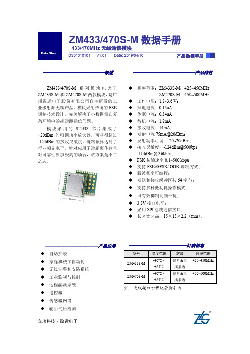
——————————————概述ZM433/470S-M 系列模块包含了ZM433S-M 和ZM470S-M 两款模块,是广州致远电子股份有限公司自主研发的工业级射频无线产品。
模块采用传统的FSK 调制技术设计,完美解决了小数据量在复杂环境中的超远距通信问题。
模块采用的SI4438芯片集成了+20dBm 的可调功率放大器,可获得超过-124dBm 的接收灵敏度,链路预算达到了行业领先水平,针对应用于远距离传输且对可靠性要求极高的场合,该方案是不二之选。
——————————————产品特性◆ 频率范围:ZM433S-M :425~450MHzZM470S-M :450~500MHz◆ 工作电压:1.8~3.6 V ; ◆ 掉电电流:0.15uA ; ◆ 休眠电流:0.34uA ; ◆ 待机电流:1.8mA ; ◆ 接收电流:14mA;◆ 发射电流75mA@20dBm ; ◆ 发射功率可调:-20~20dBm ; ◆ 接收灵敏度:-124dBm@500bps ,-114dBm@9.6kbps ;◆ FSK 传输速率0.1~500 kbps ;◆ 支持FSK/GFSK/ OOK 调制方式; ◆ 载波频率可编程;◆ 发送和接收缓冲区共64字节; ◆ 支持多种低功耗操作模式; ◆ 可有效抑制同频干扰;◆ 3.3V 接口电平;◆ 采用SPI 总线通信接口;◆ 长×宽×高:15×15×2.2(mm )。
————————————产品应用◆ 自动抄表 ◆ 家庭和楼宇自动化 ◆ 无线告警和安防系统 ◆ 工业监视与控制 ◆ 远程灌溉系统 ◆ 遥控器 ◆ 传感器网络 ◆ 轮胎气压检测ZM433/470S-M 数据手册433/470MHz 无线通信模块立功科技·致远电子修订历史目录1. 产品简介 (1)1.1产品简介 (1)1.2产品选型 (1)2. 尺寸图 (2)2.1产品尺寸 (2)2.2卷带包装 (2)3. 引脚说明 (5)3.1引脚排序 (5)3.2引脚定义 (5)4. 电气参数 (6)4.1极限参数 (7)4.2静态参数 (7)5. 射频参数 (8)6. 生产指导 (9)6.1推荐回流温度曲线 (9)7. 硬件设计注意事项 (10)7.1最小系统 (10)7.2电源设计 (10)7.3RF设计 (10)7.3.1PCB板载天线设计指导 (10)7.3.2外接天线设计指导 (11)7.3.3邮票孔天线接口设计指导 (11)7.3.4天线匹配 (13)8. 免责声明 (15)1. 产品简介1.1 产品简介ZM433/470S-M系列模块是广州致远电子股份有限公司基于Silicon Labs公司Si4438自主研发的一款工业级射频无线产品。