SP3D
SP3D在管道设计中的常见错误提示与解决方案

SP3D在管道设计中的常见错误提示与解决方案SP3D是一款广泛应用于管道设计的软件,它能够帮助工程师快速高效地完成管道设计工作。
在使用SP3D进行管道设计的过程中,常常会遇到一些错误提示,这些错误可能会影响设计的质量和效率。
了解常见的错误提示及其解决方案对于提高工程师的工作效率和减少错误是非常重要的。
1. 错误提示:材料未找到在使用SP3D进行管道设计时,有时候会遇到“材料未找到”的错误提示。
这可能是由于管道设计所需的材料没有被正确导入到SP3D中或者导入的材料名称有误所导致的。
这会导致工程师在设计过程中无法正常选择正确的材料,影响设计的准确性。
解决方案:首先要确保所需的材料已经被正确导入到SP3D中,并且其名称和属性设置正确。
还可以检查一下软件中的材料库,确保所需的材料信息已被正确添加。
在导入材料时,还要注意不同材料的单位和属性是否正确设置,以确保在设计过程中能够正确选择所需的材料。
2. 错误提示:管道连接不成功在进行管道连接时,有时候会遇到“管道连接不成功”的错误提示。
这可能是由于管道连接点的位置不正确或者管道连接方式选择错误所导致的。
这会影响管道设计的连续性和正确性。
解决方案:在进行管道连接时,要确保连接点的位置准确,以确保管道连接可以顺利完成。
还要注意选择正确的管道连接方式,确保连接点的类型和属性设置正确。
还可以在设计过程中使用SP3D中的辅助工具对连接点进行精确定位,以避免出现连接不成功的情况。
解决方案:在进行管道设计时,要仔细了解设计要求,根据设计规范和要求合理选择管道尺寸。
还要注意在SP3D中正确设置管道尺寸和属性,确保所选用的管道尺寸符合设计要求。
还可以使用SP3D中的管道尺寸检测工具来对管道尺寸进行检查和调整,以确保管道设计的合理性和符合性。
以上就是在使用SP3D进行管道设计时常见的错误提示及其解决方案。
通过了解这些错误提示的原因和解决方案,工程师可以更加高效地使用SP3D进行管道设计,并提高设计的准确性和合理性。
SP3D在管道设计中的常见错误提示与解决方案
SP3D在管道设计中的常见错误提示与解决方案
1. 模型错误提示:这是由于模型中存在错误、不完整或不兼容的元素导致的。
解决方案是检查模型结构,确保所有使用的元素都正确并且兼容。
2. 连接错误提示:这是由于管道连接配置错误导致的。
解决方案是检查连接设置,确保所有连接都正确并且符合设计规格。
8. 碰撞错误提示:这是由于管道和其他元素之间的碰撞导致的。
解决方案是检查碰撞检测结果,并调整管道和其他元素的位置,避免碰撞。
为了避免这些错误,在使用SP3D软件进行管道设计时,可以采取以下几点注意事项:
1. 仔细阅读和理解设计规格:确保在设计过程中遵循设计规格,并正确地配置管道和元素的属性。
2. 定期进行模型检查:在设计过程中定期进行模型检查,以确保模型的准确性和完整性。
4. 使用正确的材料属性:在设计过程中使用正确的材料属性,并确保所有管道使用的材料都符合设计规格。
5. 确保坐标系和坡度设置正确:在设计过程中,确保所有管段的坐标系和坡度设置正确,并且坡度符合设计规格。
6. 检查排水和安装配置:确保排水和安装系统的配置正确,并且管道和设备正确安装并与系统连接。
7. 定期进行碰撞检测:在设计过程中,定期进行碰撞检测,并及时调整管道和其他元素的位置,避免碰撞。
使用SP3D软件进行管道设计时,遵循设计规格、仔细配置管道属性、定期进行模型检查和碰撞检测,是避免常见错误的有效方法。
对于出现错误提示的情况,及时进行排查和调整,确保管道设计的准确性和完整性。
sp3d基础操作中文教程
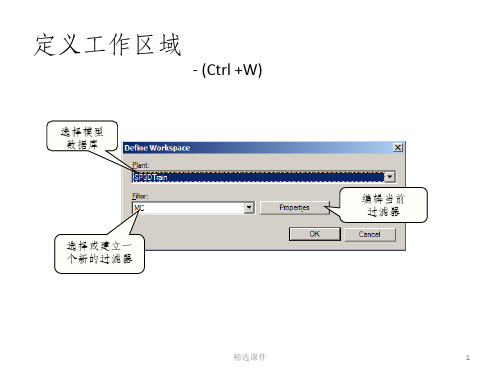
位置关联
• 连接点关联
- 强制一台设备的一个端口与另外一台设备的一个端口连在一起
- 绝对移动命令
精选课件
26
位置关联
• 最小距离关联 (E-W, N-S, Vertical)
- 在一个三维点与一个面之间关联
Surface
3D Point
精选课件
27
位置关联
• 平行关联
- 只旋转被选择的设备产生约束
46
长度控制工具
输入或选择一个长度值,它是当前路径长度 - Length Lock: Lock or unlock the length field. -By Default: 动态显示从上一个拐点或前一次直管段的连接点到当前 布置点的长度 -能够记忆前10次保存的长度值
精选课件
47
利用 PinPoint 命令布置管线
定义目标点 (即临时 0,0,0点)
[F12]
将当前使用的坐标系统的 原点设定为(0,0,0)点
打开或关闭 跟踪显示动 态坐标 [F9]
跟踪关联
指定当前 坐标系统
矩形坐标系 统或球形坐
标系统
精选课件
48
角度控制工具
输入或选择一个角度 - Angle Lock: 锁定或非锁定当前激活角 - By Default: 动态显示光标移动时所产生的虚线与前一次放置的管 段之间的夹角 - 当工作面设定为 NO Plane 时,当前激活角只能设定为0度或90度
• 设备与设备之间 • 外形与外形之间 • 设备部件与设备部件之间
精选课件
33
设备
外形体
• 点击一次即放置 • 激活参考放置步骤提示 • 放置时可用键盘上的箭头键旋转方向
精选课件
SP3D在管道设计中的常见错误提示与解决方案
SP3D在管道设计中的常见错误提示与解决方案【摘要】本文旨在探讨SP3D在管道设计中常见的错误提示及解决方案。
在引言中,我们将简要介绍SP3D软件在管道设计中的重要性。
在将详细列举SP3D在管道设计过程中可能出现的常见错误提示,如材料库缺失、连接错误等,并提供相应的解决方案和操作技巧。
通过对这些错误进行深入分析和解决方案的讨论,读者可以更好地理解和应对在管道设计中遇到的挑战。
在我们将总结本文的主要内容,并强调SP3D在管道设计中的重要性和应用价值,为读者提供一个全面的认识和指导。
通过本文的阅读,读者能够更加熟练地应用SP3D软件进行管道设计,提高工作效率和准确性。
【关键词】SP3D、管道设计、常见错误提示、解决方案、引言、结论1. 引言1.1 引言SP3D是一种广泛应用于管道设计中的软件,它能够帮助工程师实现高效、精确的设计工作。
在使用SP3D进行管道设计过程中,有时会遇到一些常见的错误提示,这些错误可能会影响设计的准确性和效率。
了解这些错误提示以及相应的解决方案是非常重要的。
在本文中,我们将重点讨论SP3D在管道设计中常见的错误提示和解决方案。
通过学习这些内容,您可以更好地应对在使用SP3D软件过程中遇到的各种困难,提高设计工作的质量和效率。
在接下来的我们将详细介绍SP3D中可能出现的各种错误提示,并提供相应的解决方案。
希望这篇文章能够帮助您更好地理解和应用SP3D软件,顺利完成管道设计工作。
让我们一起来探讨SP3D在管道设计中的常见错误提示与解决方案吧!2. 正文2.1 SP3D在管道设计中的常见错误提示与解决方案1. 错误提示:管道连接不对称。
解决方案:检查管道连接点的坐标和方向是否正确,可以使用SP3D的“连接检查”功能来验证连接点是否匹配。
2. 错误提示:管道孔尺寸错误。
解决方案:确保在管道设计中输入正确的孔尺寸数据,可以通过验证设计规范来避免这种错误。
3. 错误提示:管道弯曲半径过小。
SP3D在撬块化设计中的应用
块化设备,使气田建设速度得到显著提升。
到了20世纪90年代,我国首次将该技术引入油气田开发项目中,并取得理想的应用成果。
近年来,在四川、吉林、新疆等地陆续开始普及该技术,其凭借独特优势得到更多的认可,优势效果十分显著。
在撬块化设计中,因空间布设较为紧密,需要在有限的空间中安装管线、阀门、支架等多项内容,设计者需要思考如何使配管空间走向更加科学,但二维图纸设计不够直观,对设计质量产生严重影响;如:撬块设计不够精细、管线接口处存在误差等,均会影响预制工作的顺利开展,质量安全无法得到保障,且设备安装后很可能无法与其他管线衔接,增加后期修改工作量,甚至需要重新调整或制造,增加了工作难度。
二维设计通常由人工计算用料量,受人为因素影响设计用量与实际需求有所出入,导致预制阶段采购量增加,对施工进度和质量产生极大不良影响,导致材料浪费,投资数量增加。
2 SP3D在撬块化设计中的应用价值当前科技迅猛发展,3D 软件在工程设计中的辅助作用不容小觑,SP3D 软件由美国研发而成是当前智能工厂设计领域的潮流产品,以数据库建设为核心,依靠计算机编译数字信息,不支持文字信息编译,需要将文字转变为数字形式传输到计算机中。
其中,AllCodeLists 可将多种有效信息分类,各类文字与数字相对应,标记的文字数量较多,以管道为例,需要对尺寸、材质、压力、壁厚等指标信息进行全面标记,并将各项特征汇总在表格上。
此外,还利用Speci f i cation 部分对管道等级进行划分,依靠Catalog 将真实的管道参数体现出来。
通过数据库的应用转变为模型,将管道、设备与支架等直观展现出来。
2.1 多专业协调设计该软件可创建一个多专业综合化的协同设计平台,不但支持工艺配管,还可使电气、自控与水处理等多专业同时在平台中设计,不同专业之间的布设情况可共享,有效避免错、漏、碰撞等情况发生,使设计质量和效率得到全面提升。
在建模中虽然需要0 引言当前油气田发展速度提升,用户需求也逐渐扩大,缩短设计与建设周期成为提高企业市场竞争力的关键所在。
SP3D在管道设计中的常见错误提示与解决方案
SP3D在管道设计中的常见错误提示与解决方案SP3D是一款常用的管道设计软件,但在使用过程中,可能会遇到一些错误提示。
以下是SP3D在管道设计中常见的错误提示及解决方案:1、“No Piping System defined”: 没有定义管道系统。
解决方案:在SP3D中创建一个管道系统。
方法是:选择“Design Drafting”模块,在“Setup”下选择“Piping Systems”,然后添加新的管道系统。
3、“Invalid Slave Line selected”: 选择了无效的从线。
解决方案:选择有效的从线。
在SP3D中,从线用于将管段连接到管网中。
如果从线无效,可能需要重新定义从线。
解决方案:检查管道系统中是否存在管段。
如果不存在管段,则需要在管道系统中添加新的管段。
5、“Error Editing Attribute Data”: 编辑属性数据时出错。
解决方案:检查属性数据是否正确。
在编辑属性数据时,需要确保输入正确的数据,否则可能会引发错误提示。
6、“Node Out of Range”: 节点超出范围。
解决方案:在SP3D中,节点表示管道中的连接点。
如果节点超出范围,则可能是因为管道系统被错误地定义。
检查管道系统是否正确定义,以确保节点在正确的范围内。
7、“Invalid Tag Number Format”: 无效的标记号格式。
解决方案:在SP3D中,在为管道元素分配标记时,需要输入正确的标记号格式。
如果输入了无效的标记号格式,则可能会引发此错误提示。
总的来说,SP3D的错误提示通常与管道系统的定义和属性数据的输入有关。
因此,在使用SP3D进行管道设计时,需要仔细检查管道系统的定义和属性数据的输入,以避免出现错误提示。
SP3D管道支吊架库开发及应用

44CHEMICAL ENGINEERING DESIGN化工设计2018,28(4) SP3D管道支吊架库开发及应用刘宝洪#中海油石化工程有限公司济南250101摘要通过与传统管道支吊架设计对比,突出了SP3D软件管道支吊架库的自动化和智能化。
本文介绍软件的系统架构方案和数据,通过范例介绍了支吊架的发过程。
关键词SP3D管道支吊架软件开发石油化工行业的 发展和计算机 丨技术的不断完善,工程 已经由二 渐变为。
Sm artPlant3D*1,2](简SP3D)是鹰图公司开发的三维设计软件,是众多 工程公司重 发的新一代 成 的重要组成部分。
该软件有专门的管 的块,可以实 的!和纸的自动生成 能。
但是,SP3D面简单,这就意味软件后 要 的设置。
软件 只了,忽略了软件的定制和开发,很 f 能化的模块并没有发 有功能*!]。
管 吊架模块就是很好的例子,SP3D默认自带的管道支 库主要是以国外公司的产品为依据开发,标范、物理外形和 格都与国内不一致,不合国内工程公司实 ,不能 。
因此,公司开展了 二 发,开发了满足公司项目需求的SP3D实体支吊架库。
1系统架构方案SP3D数据库*3]结构主要有四部分组成:用于 连接项目的连接数据库集(Site D atabase S e t)、用的据库集(C atalogD atabase S e t)、放目的项目数据库(M odel D atab a s e)和用 于输出 图表的报告数据库集 (Report D atabase S e t)。
S P3D以数据为中心,软件用到的 属性和 *4,5]都 E x c e l的形在于后台,过V B程序驱动调取。
本工程为鹰图SP3D进行开发,整体的技术架构以鹰图SP3D为,据目本身的,搭建 的据 和业 。
系统整 层架构组成,统最上层为S u p p o rt模块,中层的部分为数据和A P I模块,最下层的则为基础的 SP3D模块。
SP3D在管道设计中的常见错误提示与解决方案

SP3D在管道设计中的常见错误提示与解决方案SP3D是一种用于管道设计的三维建模软件,它可以帮助工程师在设计管道系统时更加高效和准确。
在使用SP3D进行管道设计的过程中,由于各种原因,可能会出现各种错误提示,给工程师带来一定的困扰。
本文将针对SP3D在管道设计中常见的错误提示进行介绍,并提供相应的解决方案。
一、常见错误提示1. “管道可能有循环”这个错误提示通常出现在设计复杂管道系统的过程中。
循环是指管道系统中存在环路,导致软件无法正确计算整个系统的流动情况。
这个问题可能导致设计的管道系统无法正常工作。
2. “管道连接错误”这个错误提示通常出现在管道连接处存在错误的情况下。
管道连接错误可能导致管道系统无法正常运行,并且可能造成安全隐患。
二、解决方案1. 解决“管道可能有循环”错误对于管道可能存在循环的情况,可以采用以下几种解决方案:(1)重新设计管道系统,避免出现环路;(2)检查管道连接处,确认是否存在环路,并进行调整;(3)优化管道系统的布局,消除可能存在的环路。
3. 解决“管道尺寸不合适”错误对于管道尺寸不合适的情况,可以采用以下几种解决方案:(1)重新评估管道系统的尺寸设计,确保符合实际要求;(2)对不合适的管道尺寸进行调整,以确保系统正常运行;(3)优化管道系统的设计,以降低工程成本并确保系统正常运行。
为了避免在使用SP3D进行管道设计时出现以上错误,工程师在设计过程中还可以采取一些预防措施,包括:(1)在设计之前对系统进行充分的分析和规划,避免出现设计错误;(2)对管道系统的设计进行多次验证和检查,确保设计的准确性和合理性;(3)在设计过程中多与相关人员进行沟通和交流,以获取更多的反馈和建议。
- 1、下载文档前请自行甄别文档内容的完整性,平台不提供额外的编辑、内容补充、找答案等附加服务。
- 2、"仅部分预览"的文档,不可在线预览部分如存在完整性等问题,可反馈申请退款(可完整预览的文档不适用该条件!)。
- 3、如文档侵犯您的权益,请联系客服反馈,我们会尽快为您处理(人工客服工作时间:9:00-18:30)。
SP3D Object Search User SP3D Object Search User’’s Manual s ManualRev.4(Corresponding to Version 0.603)SP3D Object Search was developed to achieve conventional search of model object and create Excel report. It also provides import function from the Excel report.0. System R System Requirement equirement equirementIntergraph SmartPlant 3D 2009SP1 or higher.Database MSSQL and Oracle both supported.Microsoft Excel 2003 or higher.1. Installation InstallationCopy “SP3DOBJSearch.ocx” (for version 2009.1) or SP3DOBJSearch2009 (for version 2009SP1), “SP3DDwgLink.dll”, “SP3DIsoLink.dll”, “DwgCustom.dll” and “UserShapeDef.mdb” to your local folder, same location.Function of each file is:SP3DOBJSearch.ocx: Main SP3D custom commandDwgCustom.dll: Additional DLL required to update drawing propertiesSP3DIsoLink.dll: 2D Editor’s macro called from SP3DOBJSearch.ocxSP3DDwgLink.dll: 2D Editor’s macro called from SP3DOBJSearch.ocxUserShapeDef.mdb: Definition file for shape placerTo use main search/export/import function, only SP3DOBJSearch.ocx is required.Run regsvr32 to register program. From Start button-Run, type regsvr32 and space, then drag SP3DOBJSearch.ocx to “Run” form. Then click OK. Then complete message will be appeared as Fig.2. Repeat registration for DwgCustom.dll.Fig.1 register from RunOnce you registered, every time newer version released, update is just replace existing ocx file.Fig.2 registration succeededRun custom command2.Run custom commandThis command can be run in two different ways. One is normal command and another is command assistant. The difference of normal command and command assistant is:1)Normal command will be stopped or suspended by other command depending on itspriority. On the other hand, command assistant will continue to run. (Switching task will quit command assistant.)2)Command assistant can not modify data. Several function related to data importwill be disabled.This command needs at least one active view. Run “Tools”-“Custom commands” from any task (except catalog, drawing & report, systems & specifications which has no active view), then click “Add” button. Type “SP3DOBJSearch.Search_Object” (in case of normal command) or “SP3DOBJSearch.RunAsAssistant” (in case of command assistant) in Command Progid and set any command name (ex. SP3D Object Search)Fig.3 add new custom commandThen click OK. Select custom command and click “Run”. Main form will be shown as Fig.4.In case of command assistant, caption of main search form will be like;Fig.4 main formRun Run command command command by by by short cut key short cut keyshort cut key Right-click “Search” tab, then run “Add to Edit Menu” (See Fig.5). Two “Find” command will be added in “Edit” menu. (This change will be reflected after switching task.) You can call the custom command from simple short cut key Ctrl + F (normal command) or Shift + F (command assistant). F stands for “FIND” for many other applications.Fig.5 menu registrationFig.6 modified edit menu/Delete menu You can unregister from “Edit” menu by run “Delete from Menu” by right-click of Search tab once again.3. Search Type Search Type3.1. Search 3.1. Search by c by c by class lass lass name name nameFirst of all, you have to choose object type (=class). As SP3D has many kinds of classes, it’s hard to select from all classes, Therefore following 5 classes are registered as basic class.Equipment / Pipe Run / Pipe Line / Instrument / Specialty(These class objects have unique item tag and displayed in P&ID for most of cases.)If you want select other classes, change option from “Basic” to “Detail” then class combo box displays all type of classes which has Item Name (in other words of system which has interface IJNamedItem). However it’s very difficult to find target class from the combo box. Y ou can filter combo box entry by input part of class name in the text box next to the “Filter” button then click the button. If you want to avoid such step from next time, you can additionally register your favorite class to “Basic”. Select target class and right-click “Detail” option label and run “Add to Basic” menu (Fig.7).Y ou can reset to basic 5 classes by right-click “Basic” option and run “Initialize Basic Class”.Fig.7 add to basic/initialize basic classCheck box of “inc. EF” will include Engineering Framework object. Most of users may not have chance to check this option.If you key-in V on class combo box, detail information of class will be displayed as following and same information will be copied to clip board.Search from Business Object Tree3.2Search from Business Object TreeIf you are not familiar with class names, you can select target class from business object tree which is same as object type tab in filter definition. Simply click “BO Tree” button to display tree and select target object.(multi-selection is not allowed.)Fig.8 BO Tree tabSelect one target business object class and then click “Select” button.BO class displayed with italic font (See Fig.9 Cable Features) is not selectable because its class does not have item name property.Fig.9 BO Tree selectSearch from Drawing & report Tree3.3Search from Drawing & report TreeIf you want to search drawings/ reports, select “D&R” tab and select type of object and select snap-in folder by clicking “D&R Tree” button if required.Fig.10 drawing / report tree selectThen you can specify type of object (Iso, Ortho etc.) and status as option.For “Display Obj List” check box, see Sec 14.3.4Search by SQLSearch by SQLIf you prepare SQL text file (.sql) in the folder where SP3D Object Search exists, select one of .sql files in the combo box.SQL must have oid as first column and item name as second column which will be displayed as search result.If Internet access to is allowed, switch option to “Through Internet” to access common SQL library and select one of them.In case of SQL search, following search option will not be applied except search scope option.Execute Search3.5Execute SearchType (part of) name if necessary in text box and click “Search” button, object name list will be displayed in the right grid. Number of record will be displayed in the left section of status bar.Fig.11 search resultame search optionN ame search optionBy default partial matching is on. You can change to prefix or suffix search by clicking triangle mark next to the Search button. Also you can set match case option. (This option is valid only when the database server is Microsoft SQL server.)Search scope option4.Search scope optionBy default, search scope is whole plant. You can change search scope by clicking right of the status bar. Search scope is changed as followings by single clickPlant -> Workspace -> Select SetWhen you switch scope from Workspace to select set, program will ask you to run select by filter or not.This scope option will be ignored when you select class from D&R Tree.If you search with whole plant scope, item which is not in current workspace will be displayed with gray color.Fig.12 search scope option (click to switch)5.Search by attributeoptionSearch by attribute optionoptionIf you want to search object with specific attribute, check “Search By Att” option and select Interface /Attribute and attribute value condition. If user is not familiar with interface name, select category from combo box to restrict interface entry. If attribute type is code list type, text box will be replaced with combo box with code list. If type of attribute is number with unit of measure, number with unit will be converted to default unit value automatically. If attribute type is date, calendar control will be appeared. Here is several sample of search condition.Approved status is not “Approved” Minimum design temperature smaller than 0CSearch by created dateThe attribute search option will be ignored when you select class from D&R Tree.6.Search by volume optionSearch by volume optionYou can additionally define volume as search scope by checking “in Vol.” option. If volume is pre-defined in model data as drawing volume, zone or area, you can select one of them from space tree by clicking “Space Tree” button. X/Y/Z min/max will be automatically set in the text boxes. Clicking volume icon will fit the volume to active view.You can specify volume range manually instead of selecting pre-defined volume.By default, (inside option check off), object which part of the range is in the specified volume will be searched. By checking inside, object which the whole range is in the volume will be searched. The volume search option will be ignored when you select class from D&R Tree.Search by system option7.Search by system optionCheck “By System” option and click “System Tree” button to select target system folder from tree. Click “Select” to go back to main form with selection.Object will be searched under the system folder. (With this option search response may be slower if the model data is huge.)Search result g Search result grid operation rid operation rid operation After search result is displayed in the grid, several operations can be called from grid. a) Single click - Simply select object in the workspace and active view.b) Double click – Fit in the all views (In case of Isometric sheet, corresponding modelobject will be fit. In case of pipe line, containing pipe runs will be fit)c) Right click – Property display will be shown. After closing property form, main formwill come back. If object type is drawing, open drawing with Smart Sketch editor. In case of report, Excel report will be opened.d) “Ctrl+Delete” key – Delete object after confirmation message.e) “Insert” key – if the object is out of scope of workspace, it will be added to currentworkspace. (multi-select possible)f) Ctrl+A – selected object will be sent to relation analyzer. (See section 8.2) g) Ctrl+H – Hideh) Ctrl+S – Showi) Ctrl+C – Copy selected item list in the clipboard. (Then paste on blank Excel sheet) j) Shift+A – Set color to each cell in the name column of the grid based on your accessright. Meaning of color is;Dark yellow: read only by permission settingsMagenta: read only by approval statusWhite: full access (updatable)Gray: Other status8. Excel list export Excel list export / defining index / defining index / defining indexSearch result will be exported to new Excel workbook. Sheet name will be SP3D <class name> List. First ‘A’ column is oid and is hidden. Oid is database unique identifier which is required to export/import etc. in following section. Don’t delete the column. Second B column is item name. If you run “Export” with “Add common att” checked, allbasic attribute indexes will be added from C column. Y ou can customize (change order, delete unnecessary attribute etc.) First row is interface name and second row is attribute name and third row is user attribute name which is same as property display by default.Fig.13 Attribute index with input validation for code listMeaning of index cell color is;Pink: Read only attributeLight blue: Code list attribute typeLight green: Other attributeFor code list type attribute, data validation will be automatically set for attribute data edit support by adding code list value at the end of worksheet row.Cell color of name column will be set based on your access right same as (Shift + A) operation in the search result grid.“Append” button will add data to active sheet by comparing oid. This command is useful when user want to update list for additional object to existing Excel list.Additional data will be displayed with bold font in the name column.9.Defining index for reportDefining index for report.1 Direct attribute9.1 Direct attributeYou can create simple report without defining report template or knowledge of database structure or SQL command. Simply select required attribute and click “Add Att” button or select interface and click “Add IF” button. Additional index will be added at active excel sheet. If “Export immediately” is checked, data export will start after clicking the button.9.2 Relation object Relation object’’s attribute ( attribute (by by by Relation Analyzer)Relation Analyzer)Relation Analyzer)If you can not find required attribute, such attribute is not direct attribute of the object but relation object’s one. To define and add index of such relation object’s attribute, use relation analyzer in the “Import/Export/Relation” tab.Select one typical item in the search result grid and click Ctrl+A or select item in the exported Excel list or select one in the workspace / view and click “Get” button in Analyze Relation pane. (Get from Excel or select set is option. Click black triangle to choose.)Oid of the selected object is copied to text box and object type and name will be displayed and corresponding relation will be displayed in the combo box (Fig.14 left). If you select one of the relation in the combo box, relation object type and number will be displayed as Fig.14 right. Oids of relational object will be copied to clipboard. You can continuously search relation chain by clicking Ctrl+Z at top text box. If multi-oids are copied at clipboard, text box is automatically switched to combo box. “Fit” button will fit object in the view(s).Fig.14 Analyze RelationYou can add relation object’s attribute by selecting interface and attribute and click “Add Att List” or “Add IF” or “Add Att” same as direct attribute. Relation information will be set as note in the 1strow of Excel sheet.If you want to follow relation chain further beyond one relation, click “path” button after selecting relation in the combo box. Destination object(s) is moved to top text box andyou can continue to analyze and follow relation further.You can check accumulated path information by clicking path number. Shift + click willclear path information.Send destination Send destination object object object to grid to grid to gridIf you need destination objects list as Excel format, (for example: nozzle list for specific equipment) right click destination object label and run “Expand to grid”. Then click “Export” to create Excel list.“Report oid” button will export relation object’s oids in the active Excel list. Click with selecting blank one column (or part of one column for testing purpose.) If the number of relation object is not one, only first one oid will be exported with cell color light orange. If you click V key on the combo box of relation name, detail information of the relation will be displayed as Fig.15 and same information will be copied to clipboard. This information is useful for SQL writer of report / label templates or automation programmer.Fig.15 detail information of relation10. Export/Import/Compare Export/Import/CompareSeveral buttons are available in “Import/Export/Relation” pane. You have to activateExcel list and select target range before clicking these buttons. Following four types of selection is possible.a) Select whole sheetb) Select continuous columnsc) Select continuous rows d) Select continuous range multi region selection is not supported.Fig.16 Excel selection type for processingAttribute processing will be skipped for hidden rows, so you can apply auto-filter for processing objects.You can cancel while these processing on the way by clicking “Cancel” button displayed while processing. However, try with small selected range first, then apply processing to whole list is highly recommended.1010.1 Export .1 Export .1 ExportAfter defining indexes in section 9.1 and 9.2, you can export database value to Excel sheet by clicking this button.1010.2 Import .2 Import .2 ImportYou can edit attribute value in the Excel list and write back to SP3D database by clicking this button. If attribute type is number with unit of measure, simple number will be imported as number with default unit. You can specify number with unit like “0C” (in case of temperature) etc.1010.3 Compare .3 Compare .3 CompareYou can compare Excel value and SP3D database value to check if import works OK. If there’s difference between Excel value and database value, database value will be set as note of the Excel cell. And cell color will be green.1010.4 Undo .4 Undo .4 UndoRun undo command within this custom command. Undo is valid for import action. 1010.5.5.5 Optional Check Box Optional Check Box Optional Check Box Several option checkbox is available for export/import/compare.1010.5.1 Export without unit .5.1 Export without unit .5.1 Export without unitBy default (check off), attribute with unit will be exported with format <Value> <Unit>. Unit used is default unit of current workspace. Y ou can change it from Tools – Option menu. (Units of Measure). If checkbox is on, export format is value only.10.10.5.2 Import different data only 5.2 Import different data only 5.2 Import different data onlyIf this checkbox is on, program will compare data between Excel value and database value and only in case of different data, import will be performed.1010.5.3 Skip import if blank .5.3 Skip import if blank .5.3 Skip import if blankIf check this option, blank data will be skipped to import.1010.5.4 Single commit .5.4 Single commit .5.4 Single commitBy default (check off), commit to database will be done for every single row. By checking “Single commit”, system will do commit only once after all processing completed. The advantage of single commit is that only one undo will return to original state before processing. However last one commit takes long time if you import thousands of rows and sometime it causes memory overflow error. So I don’t recommend to check this option for huge records import.1010.5.6 Ignore capital/small letter to compare .5.6 Ignore capital/small letter to compare .5.6 Ignore capital/small letter to compareIf you compare data with list generated from other source. Sometime capital/small difference can be negligible. By check this option, compare works in this way.1010.5.7 Export multi relation object value .5.7 Export multi relation object value .5.7 Export multi relation object valueIf you define index for relational object by relation analyzer, sometimes relation can be 1 to n objects (for example, equipment to nozzle). By default (check off), export will report value for first one object only and cell color will be orange which means multiple value exists. If check this option, export will report all values in one cell delimited with carriage return. (Lf) Import is not supported for multi value export result.Sample of multi value export (equipment to nozzle)1010.5.8 Export code list value .5.8 Export code list value .5.8 Export code list valueWith checking this option, code list value will be exported / imported instead of short string value. Input validation is also set based on code list value.11. Other Processing Tab Other Processing TabIn this tab, several special processing function buttons are available which can not be achieved by simple export / import of attributes.11.11.1 Path 1 Path 1 PathThis button will export path/parent information of each object in the Excel sheet. In case of model object, path of workspace explorer will be exported. In case of drawing and report sheet, drawing tree path will be exported.By default, full path information is selected as option. Click black triangle and select option as necessary.Fig.17 path option1111.2 .2 .2 NR NR NR (Naming Rule Naming Rule))This button will export naming rule information of each object in the Excel sheet. Input validation will be automatically set for each cell to change it. (See 11.1 Set NR)Fig.18 naming rule validation1010.3 Moniker .3 Moniker .3 Moniker“Moniker” is unique identifier maintained in SmartPlant Review property data. By exporting this information into Excel sheet, you can find corresponding object inSmartPlant Review model data. (Use another tool “SPR Moniker Sync.exe” which is also available at )11.4 Project 11.4 ProjectThis button will export WBS project information of each object in the Excel sheet. 1111.5.5.5 WBS WBS WBSThis button will export WBS information of each object in the Excel sheet. System will ask you full path of WBS tree (Yes) or upper parent WBS (No).1111.6.6.6 P&ID DWG P&ID DWG P&ID DWGThis button will be active when the plant is connected with SmartPlant Foundation. If you use P&ID correlation function, corresponding P&ID name can be exported. This export is valid only for equipment, pipe run and piping component (includes instrument and special parts.)1111.7.7.7 Object Class Object Class Object ClassThis button will export object class name of each object.1111.8.8.8 Report Tree Report Tree Report TreeThis button will create new Excel workbook which display hierarchy report as shown below. Four type of option is available. Click black triangle to choose option. First hidden column is oid, second column is hierarchy with name and third column is object class name. You can additionally define attribute and do export/import for this work sheet too.1111.9.9.9 Save file with HL (HL: hyperlink) Save file with HL (HL: hyperlink) Save file with HL (HL: hyperlink)This function will work only for drawing sheet list or report list. Select one columnwhich is not blank (name column normally) then click this button. You have to save Excel list in any folder to add hyperlink. Drawing/report files are saved under that folder with relative path of drawing snap-in tree. You can create document list with link easily. If you check “Read Only Attribute” and run, saved file has read only attribute to avoid editing by SmartSketch editor.1111.10.10.10 Isogen Error Isogen Error Isogen ErrorThis button is valid only for Isometric sheet list. It’s tedious to check this error to open “View Extraction Data” one by one in the drawings & reports task. You can create error report of Isogen easily.Fig.19 Isogen error sample1111.11.11.11 Number of sheet Number of sheet Number of sheetThis button is valid only for isometric sheet list. This button will save isometric drawing file in temp folder and count number of sheet. So this process takes longer time thanother processing (several second per sheet)11.12 oid from Name 11.12 oid from NameThis command will find/export oid (database unique identifier) by name as key. This command may be useful to compare Excel list created by other tool (SPPID, Tekla etc.) and import data.To specify class, select one at class tab in the main search tab to avoid name duplication. 11.13.13 Set Path Set Path Set Path (disabled when assistant mode) (disabled when assistant mode) (disabled when assistant mode)You can change parent system object (ex. pipe line for pipe run object) by editing full path information in the Excel sheet and click this button. This button never create new system object, you have to create system object manually before clicking this button. If such system path does not exist, the cell color will be dark red which means failed to set parent.11.14.14 Set NR (Naming Rule)Set NR (Naming Rule) (disab (disabled when assistant mode)led when assistant mode)led when assistant mode)This button will set naming rule of the each object. Edit on Excel sheet and select range then click button.11.15 Set WBS 11.15 Set WBS (disabled when assistant mode) (disabled when assistant mode) (disabled when assistant mode)This button will set WBS of the each object. Edit on Excel sheet and select range then click button. Excel data can be WBS item name or full path of WBS tree. If you specify WBS item name, name must be unique in all WBS items. System will automatically claim to parent WBS project.11.16 Clear WBS Assignment 11.16 Clear WBS Assignment (disabled when assistant (disabled when assistant (disabled when assistant mode) mode) mode)This button will cut relation to WBS item. If you set “Release claim” on, release claim to project as well.1111.15.15.15 Import/Replace file Import/Replace file Import/Replace fileThis button will write drawing files back to database. Select hyperlink column created by 10.6 then click this button. By combining these save and import button, you can edit drawings off-line. Manual drawing modification work can be done without SmartPlant 3D.11.1411.14 SmartPlant Review related SmartPlant Review related SmartPlant Review relatedFour graphical buttons and two download link available.System hierarchy System hierarchy ex ex export portport: Select SmartPlant Review file then start to export system treeinformation file (.mdbtr2) which is used by SmartPlant Review Explorer2.S pace hierarchy export:pace hierarchy export: Select SmartPlant Review file then start to export space tree information file (.mdbtr2) which is used by SmartPlant Review Explorer2.export:WBS hierarchy export: Select SmartPlant Review file then start to export WBS tree information file (.mdbtr2) which is used by SmartPlant Review Explorer2.Tag snapshot viewerTag snapshot viewer: Call snapshot view form from main search form. For how to use, see <Additional Command 2> SmartPlant Review Tag Viewer12. Excel Excel List List List -- 3D view synchronize 3D view synchronize function function functionThis button will switch to Excel link mode. Activate any Excel list created by this command and click Excel icon at left-bottom of the main form.Fig.20 Excel link functionMain form will be hidden while this mode.Select any row(s) will select and fit in the all 3D views.Fig.21 right-click menu while link modeRight-click and property will open property display.Open drawing will be active for drawing report sheet object list to open corresponding drawing/report.Update drawing will also be active for drawing sheet object to update drawing.Double click on Excel sheet will stop sync mode to normal condition to display main form.Dark pink Excel button is one time jump to selected object(s) in the Excel list.13. Isometric Drawing link function Isometric Drawing link functionFig.22 Iso link modeThis button will be enabled when “SP3DIsoLink.dll” is located in same folder as main macro “SP3DOBJSearch.ocx”. Before click this button, you have to open Isometric drawing by SmartSketch editor by right-click Iso sheet in the search result grid or from “Tools”-“Drawing Console”. After click this button SmartSketch macro will be run.Fig.23 point out cursor typeIf mouse cursor is on the piping component object, cursor type will be change as Fig.23 and click will select corresponding 3D object in the active view. Shift+Click will fit object in the 3D view.Double clicking on the Iso sheet will quit this macro.Drawing / Object list link functionwing / Object list link function14.Drawing / Object list link functionIf you open drawing (Iso, Ortho, Composed) by right-clicking search result grid with “Display Obj List” checked. Object list form will be open. This list included objects displayed in the drawing.Fig.24 Display Obj List check boxSame as search result grid, single click will select object in the workspace and double click will fit object in the active 3D view.Right click will highlight object in the 2D drawing and Shift + right-click will fit object in the 2D drawing.You can filter list by object type (class). View name combo box will be enabled only when drawing consists of multi-view.Ctrl+C will copy whole list information to clipboard.When you close DWG Object List, system will ask you to quit SmartSketch editor.。