通用型多功能电源安全检测仪说明书IV(电子版)
多功能数显表使用说明书
..' 多功能电力监测仪使用手册版本:3.0杭州正普科技有限公司使用前必读在您使用本产品之前,请务必仔细阅读此使用手册内容,正确按照用户手册指导操作,这会有助于您更好地使用本产品,并有助于解决现场出现的各种问题。
1、监测仪在施加工作电源之前,务必确保工作电源在仪表规定范围之内;2、现场安装使用时,电流输入端子严禁开路,电压输入端子严禁短路;3、通讯端子(RS485)严禁施加高压;4、使用时仪表接线方式务必与内部系统设置方式一致;5、与后台通讯时,仪表通讯参数务必与后台一致;不能带电拔插通信接口;6、本手册中的信息如有变动,恕不另行通知;我公司自始至终本着“质量第一服务第一”的宗旨,将以优质的产品、优良的服务奉献给国内外用户!●使用前请仔细阅读本用户使用手册●请注意妥善保存目录一、概述-------------------------------------------------- 1二、型号定义---------------------------------------------- 1三、尺寸对照表-------------------------------------------- 1四、型号与功能对照表-------------------------------------- 2五、技术指标---------------------------------------------- 3六、外形及安装尺寸---------------------------------------- 4七、接线图------------------------------------------------ 6八、操作说明---------------------------- 7(RS485通讯规约、CT/PT设置、开关量操作、变送输出操作)..'一、概述多功能电力监测仪具有对电网中电流、电压、频率、有功功率、无功功率、视在功率、电能、功率因数等进行同时测量的功能。
多功能仪表使用说明书
6. 电能脉冲 仪表提供有功、无功电能两路脉冲输出,采用光耦集电极开路方式实现有
功电能和无功电能脉冲的远传,远程的计算机终端、PLC 或开关量采集模块采集
多功能电力监测仪表
使用手册 USER MANUAL
目录
安全须知...................................................1 一、产品说明...............................................2
1.1 概述................................................2 1.2 选型................................................2 1.3 测量................................................3 1.4 需量................................................4 1.5 电能计量............................................4 1.6 电能脉冲............................................5 1.7 开关量输入..........................................6 1.8 继电器输出..........................................6 1.9 模拟量输出..........................................7 1.10 通信...............................................7 1.11 电能质量...........................................7 二、安装与接线.............................................8 2.1 安装尺寸............................................8 2.2 外形尺寸............................................9 2.3 安装................................................9 2.4 接线................................................9 三、操作......................................... .........11 3.1 仪表面板.......................................... .11 3.2 显示............................................... 12 3.3 显示界面总览....................................... 14 四、设置...................................................15 4.1 查看系统参数....................................... 15 4.2 进入和退出编程状态................................. 15 4.3 设置菜单总览....................................... 15 4.4 设置菜单说明....................................... 19 4.5 通信设置........................................... 21 4.6 输入信号设置....................................... 22 4.7 报警项目表........................................ .23 4.8 变送和需量项目表...................................24
通用型多功能电源安全检测仪说明书IV(电子版)

科技以安全为本产品以用户为尊通用型多功能单相插头式电源检测仪使用说明书DTX系列单相插头式电源安全检测仪是我司积十多年经验,综合各种不规范的电源插座接线方式研制出来的安全用电保障系列产品之一,它主要用于电器安装前检查电源插座接线是否正确,也方便用户用来对已使用的插座进行检验,及时从源头上查找隐患,为用户用电安全提供保障,具有操作简单、品质可靠、便于携带的特点。
其中DTX-t-Ⅳ是我公司把可用于10A和16A插座的DTX-t-Ⅲ的功能加以扩展而开发的第四代产品,它同时还可以用于检验家居漏电保护开关状况、接地系统状况。
一、性能简介1、特征:本产品用于检测电源插座的地极是否带电,各极是否按照规定要求连接,以及家居的用电安全保护系统是否正常,能及时提醒用户对有故障及安全隐患的插座作调整,和对保护系统进行检修,确保家居用电安全。
本产品10A、16A插座通用。
2、型号及其含义D T X–t–Ⅳ第四代产品通用型(10A、16A插座通用)插头式检测电源3、主要技术指标二、产品外型图三、使用方法1、取下铜脚护套,对应插座的规格(10A或16A)按指示转动中脚180度到相应位置,然后插至被检的插座上,首先按下右下角按键(勿戴手套操作),白光指示灯不亮,然后再观察第一排红灯,当右边两盏红色指示灯亮,表示该插座电源极性连接正确。
(两个步骤分开操作,前面操作要按按键并观察白灯,而不必管三盏红灯发亮的状态,后面操作只需观察三盏红灯发亮的状况。
)2、红灯其它指示方式均表示电源连接有误,应按相应指示进行纠正,特别是按下右下角按键,白灯亮为地线带电的,千万不得使用,否则会引起严重事故!3、电源保护系统的检查3.1、按动试验/断电按钮,灯亮/报警指示灯不亮且“电源插座接线检查”的指示灯全部熄灭,表明家居电源保护系统完全正常,是接地保护系统,家居漏电开关处于正常工作状态。
(需重新接通家居漏电开关恢复供电)3.2、按动试验/断电按钮,灯亮/报警指示灯亮会有下面几种情况:(1)、用户没有漏电开关,或者漏电开关的IΔn>30mA;(2)、漏电开关已损坏,可通过漏电开关试验键作进一步检查;(3)、用户有漏电开关且经检查是正常的,则该电源插座是采用接零保护系统。
多功能数显表使用说明书
多功能电力监测仪使用手册版本:杭州正普科技有限公司使用前必读在您使用本产品之前,请务必仔细阅读此使用手册内容,正确按照用户手册指导操作,这会有助于您更好地使用本产品,并有助于解决现场出现的各种问题。
1、监测仪在施加工作电源之前,务必确保工作电源在仪表规定范围之内;2、现场安装使用时,电流输入端子严禁开路,电压输入端子严禁短路;3、通讯端子(RS485)严禁施加高压;4、使用时仪表接线方式务必与内部系统设置方式一致;5、与后台通讯时,仪表通讯参数务必与后台一致;不能带电拔插通信接口;6、本手册中的信息如有变动,恕不另行通知;我公司自始至终本着“质量第一服务第一”的宗旨,将以优质的产品、优良的服务奉献给国内外用户!●使用前请仔细阅读本用户使用手册●请注意妥善保存目录一、概述-------------------------------------------------- 1二、型号定义---------------------------------------------- 1三、尺寸对照表-------------------------------------------- 1四、型号与功能对照表-------------------------------------- 2五、技术指标----------------------------------------------3六、外形及安装尺寸---------------------------------------- 4七、接线图------------------------------------------------ 6八、操作说明----------------------------7(RS485通讯规约、CT/PT设置、开关量操作、变送输出操作)一、概述多功能电力监测仪具有对电网中电流、电压、频率、有功功率、无功功率、视在功率、电能、功率因数等进行同时测量的功能。
电子产品安全测试仪说明书

Introduction The Guardian 6100 Plus is the industry’s first production safety analyzer with simultaneous Hipot and Ground Bond capability providing a dramatic savings in test time. Six instruments in one, the G6100 Plus provides AC Hipot, DC Hipot,Insulation Resistance, Leakage Current/Functional Run, Ground Bond and Open/Short measurements from a single test connection. Versatile and packed with features, the G6100 Plus is a cost effective solution for the full spectrum of electri-cal safety compliance testing.DescriptionTwin Port Technology:This patented feature allows for simulataneous Ground Bond andHipot Testing. Decrease test time and increase device through-put.Leakage Current: With 20A input current capability, Leakage Current can be measuredfrom 0.1µA to 9.999mA.Perform Functional Run Tests while monitoring the V oltage,Current or Power plus perform Earth, Enclosure and Patient leakage testing in 8 possiblemodes including Normal, Reverse Line, Single Fault Normal and Single Fault Reverse.Ground Bond:With test current from 1A to 30A in 0.1A steps and programmable currentlimits, test time, frequency and open circuit no load voltage, the G6100 Plus provides fullGB testing capability. A 40Amp GB option is also available.AC Hipot: AC dielectric testing over the voltage range from 50V to 5000V AC RMS. Themaximum leakage current of 40mA RMS is ideal for testing devices with high leakage cur-rents such as power supplies which have large filter or “Y” capacitors for noise reduction.DC Hipot: DC dielectric testing from 50V to 6000VDC with a resolution of 1V . Leakagecurrent can be continuously monitored from 0.1µA to 12mA DC.Insulation Resistance:The G6100 Plus is capable of measuring IR from 100k to 50G Ωwith test voltage from 50V to 1000VDC in 1V steps.Open/Short Circuit Detection Mode:Avoid false pass results by checking for Open andShort connections and ensure that the DUT is properly connected not shorted.Optional Scanners:Increase the number of test channels for multi-point or multi-devicetesting by adding an external scanner to the G6100 Plus. Add up to 8HV channels or a com-bination of HV and GB channels with just one external scanner.Standard Interfaces:The Remote I/O and RS-232 interfaces provide remote control andserial data collection capability for automated applications.Guardian 6100 Plus Safety Analyzerfor Electronics Production & Compliance Testing Hipot Testers • LCR Meters • Cable Testers • AC/DC Programmable Power Sources• Megohmmeters • MilliohmmetersFor more detailed information on specifications, pricing and special purchase, rent and lease options,contact us at: 800-253-1230 1981AC Output Voltage:Range: 50V to 5000V AC, 1V resolution Regulation: <(1% of setting +5V) at Rated Load Freq: 50-600 Hz, programmable in 1Hz steps 50~60Hz : 1% + 5 cnts, > 60Hz: 3%+10 cnts Waveform: Sinusoidal Voltage Display:Accuracy: ±(1% of reading + 5V)Resolution: 1Volt AC Current Display:Total current, Range: 0.001 to 40mA AC Resolution: 1 or 10µA steps Accuracy: ±(1% of reading + 5cnt)High/Low Limit Test:1µA to 40mA AC Low limit can be turned OFF Arc Detection:Programmable 1-20mA, Pulse Width 40µ, 20µ, 10µor 4µsec DC Output Voltage:Range: 50V to 6000V DC, 1V resolution Regulation: <(1% of setting +5V) at Rated Load Voltage Display:Accuracy: ±(1% of reading + 5V)Resolution: 1Volt DC Current Display:Range: 0.1µ to 12mA DC Resolution: 0.1, 1 or 10µA steps Accuracy: ±(1% or reading + 5cnt)High/Low Limit Test:0.0001mA to 12mA DC Low limit can be turned OFF Arc Detection:Programmable 1-10mA Pulse Width 40µ, 20µ, 10µor 4µsec Insulation Resistance:Range: 100k V - 50G V Accuracy: ±5% to ±15% depending upon voltage and resistance Voltage Range: 50V to 1000V DC Voltage Accuracy:±(1% of setting + 5V)High/Low Limit Test:100k Ω- 50G ΩLow limit can be turned OFF Ground Bond:Output Current:Range: 1.0 to 30.0A AC, setting 0.1A/step; *40A Accuracy: ±(1% of setting + 0.3A)Frequency: 50 or 60Hz Selectable No Load Voltage: 6 to 15 V Programmable Resistance:Range: 0.1m Ω-510.0m V , 4 digits; Resol: 1m V Accuracy: ±(1% of reading + 3 counts) High Limit:0.1m Ωto 510m ΩStart Wait:0.1 - 99.9sec, OFF Leakage Current:Input Voltage:Range: 0V to 300V Line Voltage Meter:0 - 300V AC, ±(1% of reading + 6cnts)Line Current Meter: 0 - 20A, ±(1.5% of reading + 0.1A)Power: 0 - 4400VA High/Low Limits: Programmable for Voltage, Current, Power Current Display:Range Res.Accuracy 0.0001-0.59mA 0.0002mA ±(2% + 5cnts)0.6 - 9.999mA 0.003mA ±(2% + 5cnts)Current Trip Limits:0.1µA to 9.999mA, 1µA Resolution (Range Dep.)0.1µA to 6.000mA for UL544NP Measuring Circuit: 5 Human Body Models IAW UL544 NP ,UL544P , UL1563, UL2601-1,IEC60601-1, IEC 950, UL1950, UL3101 Standards Measurement Modes:Normal, Reverse, Single Fault with Ground ON/OFF, Earth Line Leakage, Patient Line Leakage and Patient Auxiliary Leakage.Max. DUT Current:20A Common Features:Open/Short Circuit Mode:Check for Open & Short against a standard capacitance value (Cs); <100V, 600Hz Offset Function:0 to 100m Ωoffset, user selectable Test Time:Ramp: 0.3 to 999s (±20ms), AC/DC/IR Dwell: 0 to 999s (±20ms), DC only Start Wait: 0.1 to 99.9s (±20ms), GB only Test: 0.3 to 999s (±20ms) & Continuous (ALL)Remote Control:Inputs: Start,Stop Characteristics: Optically Isolated, Low,Pulse Width >1ms.Outputs: Pass/Fail/Under Test Characteristics: Dry Contact relay Electrical Characteristics: 120V 100mA max.Logic: Closed if True Connector: Terminal Strip and 9 pin D Series Test Setups:100 Test Setups with 50 Steps each,13 character Alpha-Numeric Label Connectors:Front and Rear 4- terminal connection Display:320 x 240 enhanced LCD with status indicators Front Panel Lockout:Key Lock w/ Password; Fail Lock w/ Password Safety Features:Fast Cutoff (<0.4ms) & Fast Discharge (0.2s)Adjustable Discharge: .05-5.1kV DC Miscellaneous:Fail Retest; Continue on Fail PAUSE Mode: Program pause between stepsIndication: Pass/Fail lights, audible sound; Remote, Lock,Offset & Error status indicators Interfaces:Std RS-232, Remote I/O Opt IEEE-488, PrinterDimensions:(w x h x d):17x5.25x18.5in (430x133x470mm)Weight: 53 lbs (24kg) - Net, 60 lbs (27kg) Shipping Environmental:Operating: 0 to + 40° C; Humidity: <75%Storage: - 20 to + 70° C Power:• 90 - 130V AC • 50 or 60Hz • 200 - 250V AC • 800W max Guardian 6100 Plus Safety Analyzer Includes:150799Instruction Manual S02HV Lead Set, 1m G15Ground Continuity Lead Set G30Corded Product Adapter G33Power Entry Adapter 4200-0300AC Power Cable 5201578A 250V Power Line Fuse 5200534A 250V Power Line Fuse 52012420A 250V Power Line Fuse: Scanner N/A Calibration Cert. Traceable to NIST Optional Accessories N/A Calibration Data 5000-01External Scanner, 8 Channel: 8HV 5000-02External Scanner, 8 Channel: 8HV, 4GB 5000-03External Scanner, 8 Channel: 8HV 5000-04External Scanner, 8 Channel: 8HV, 3GB S04HV Lead Set 2m S05Foot Switch S08Gun Probe S09HV Lead, 1m, Unterminated S10HV Lead, 1m, Unterminated G13Corded Product Adapter (115V)G14Power Entry Adapter G16International Power Strip G24Scanner Cable (5000 scanners)G25Corded Product Adapter (240V)G31Isolation Transformer, 500VA G32Isolation Transformer, 1000VA G38Printer Interface (replaces IEEE)G39IEEE-488 Interface G43Rack Mount Kit G44Barcode Scanner G4540A Ground Bond Transformer 630157RS232, 9-pin (M-F), 10’ length Ordering Information Guardian 6100 Plus *GB to 40A with optional transformerFor more detailed information on specifications, pricing andspecial purchase, rent and lease options, contact us at: or 800-253-1230P/N: 030147/A4。
某品牌的多功能电测仪说明书
2000
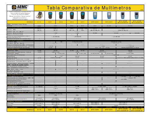
600 V CA/CC •/0 MΩ <30 Ω
0-1 V -/-
Temperatura - Termopar tipo J / tipo K
-/-
Ciclo de trabajo / Ancho de pulsos / Cuenta ∆ REL - Función de medida relativa dB - Decibeles en tensión (Vref) dBm - Decibeles en potencia (Rref) MÁX / MÍN / Pico+ / Pico CF - Factor de cresta Potencia - Resistiva / VxA Función MATH - Cálculos matemáticos con m OTRAS CARACTERÍSTICAS Registro - (# de registros) Comunicación con computadora - USB / Blu Software para análisis de datos Pantalla gráfica a color Retroiluminación / Linterna Desactivación de apagado automático ALIMENTACIÓN
Todos los Modelos (*excepto 5115): Continuidad con señal acústica, Función de retención HOLD ,
Rango automático, Rango manual*, Apagado automático*,
Acceso directo al fusible*
在使用前请仔细阅读说明书-电力测试设备
在使用前请仔细阅读说明书一、概述HTJBC-IV型继电保护测试仪是在原有JBC—III的基础上,新开发的高智能化,多功能继电保护校验仪器。
本仪器采用单片微机技术,由自动同期数字毫秒表,逻辑控制单元,多功能数显单元,高精度数据采集及处理单元,电流、电压输出单元,过载及超量程保护单元等部分组成,自带打印及显示,测试过程全自动,大大提高测量精度及工作效率。
该仪器还具有外形美观,性能可靠,操作简便,功能较齐全等优点,是校验继电保护装置理想的仪器。
二、功能1.本机可测试各种交直流、电流、电压、中间、自保持, 信号等多种单个继电器及整组继电保护屏,可测试各种继电器的吸合电压(电流)值,释放电压(电流)值,各种触头(常开、常闭、转换、延时)的吸合时间和断开时间,均自动测试三次并储存数,并自动计算三次均值的返回系数且打印, 可重复显示及打印测试结果。
2.本机可方便地测试重合闸继电器的各项参数。
3.本机附有测频、测相功能,可测量电流,电压的频率(显示一个周期的时间,即周期)及二个信号之间的相位差(时间)。
4.本机设有两个独立的通道,均与本机其它输出绝缘,可方便地测量带电接点,满足继电器的在线测试,接线简单,安全。
5.本机采用了精密的计时基准(10微秒)及长达999秒的计数器,所以可单独作为精密毫秒计取代传统的秒表。
三、特点1.由于本机采用了微机控制,面板上仅有16个触摸开关,就可方便的完成各种测试功能,改变了老式继保仪必须关断电源,切换多个开关,才能转换电源种类的弊病,操作简单。
本机还设有自检,报错功能,极大地方便了检查、维修。
2.本机设有全面的自检,自我保护功能,开机后本机立即投入自检,在过载和过量程时,保护电路将快速切断输出并发出声、光提醒,极大地降低了因误操作带来的不必要损失。
3. 本机智能化程度高,仅按一个键,即可测出通用继电器的全部参数,并自动打印全部数据,使您从繁锁的测试操作中解脱出来。
4.本机显示屏有功能显示单元,从显示屏上能清楚的反映本机的工作状态。
电源安全测试器说明书

When servicing electrical equipment, workers must comply with safety regulations that require a voltage verification test to validate the absence of voltage. This process includes a number of stages that can be complex and time-consuming when using hand-held portable test instruments.The VeriSafe ™ Absence of VoltageTester from Panduit simplifies this process by automating the voltage verification process.Once installed, a simple push of a button enables workers to verify the absence of voltage and see an active indication when the absence of voltage is confirmed. This provides a new and innovative way to safely, reliably, and efficiently verify the absence of voltage before accessing potentially dangerous electrical equipment.By automating this process, the VeriSafe ™ Absence of Voltage Tester:• Reduces the risk of exposure of electrical hazards for improved worker safety • Reduces testing procedure time and complexity to improve productivity • Supports compliance when used to verify the electrical lockout/tagout process as described in NFPA 70EThe VeriSafe ™ Absence of Voltage Tester minimizes risk by verifying the absence of voltage before equipment is accessed, making it easier for workers to verify an electrically safe work condition has been established in a fraction of the time compared to using hand-held portable test instruments.VeriSafe ™ Absence of Voltage TesterThe Safe Way to Verify the Absence of Voltage.in NFPA 70E-2018 120.5 (7) Exception 1 when it is installed in accordance with the ratings and instructions in the VeriSafe ™AVT Installation Manual.VS-AVT2VS-AVTOpen PanelActivate the VeriSafe ™AVTRetest the TesterPerform WorkCheck for Voltage 2C o m p a r i s o n o f T e s t i n g M e t h o d sPossible Exposure to Electrical HazardsVoltage indicators warn of hazardous voltage, but cannot be used to confirm if equipment is de-energized. Absence of Voltage Testers are permanently-mounted test devices designed to verify that a circuit is de-energized prior toopening an electrical enclosure containing electrical conductors and circuit parts.Mo r e t h a n a V o l t a g eI n d i c at o rAbsence of Voltage Testers are Fail-Safe and Reliable• Active indicators for voltage presence and absence• Safety functions meet SIL3 (IEC 61508)• Comprehensive diagnostics performed as part of each absence of voltage testConfirmation that adequate battery voltage is presentHealth check of key circuit elements including the microcontroller, firmware, and processing componentsVerification of connectivity between the tester and power and grounding conductorsVerification that the tester is detecting voltage in the desired rangeCalibration test to verify that the test circuits are within tolerance limitsRED indicators illuminatewhen hazardous voltageis present.Upstream Power: ONWhen AC voltage is not detected,indicators are not illuminated.This does not guarantee theabsence of voltage.Upstream Power: OFFPressing the "TEST" button initiatesthe voltage test, indicated by theflashing YELLOW caution indicator.Upstream Power: OFFGREEN indicator illuminatesonly when the absence ofvoltage has been verified.Upstream Power: OFF Representative image only. VS-AVT used for illustration purposes.345Indicator Module• 30mm knockout, mount on exterior of enclosure• Operate and maintain without exposure to electrical hazards • Instruction label with operating instructions • VS-AVT2 will have a blue faceplate while VS-AVT will have a yellow faceplateAVT System Cable• Connects Isolation Module to Indicator Module • 600V cable available in multiple lengths for easyinstallation• Replaceable with connectors on each end • Replaceable with additional lengths • Locking connectors on both ends• Right angle connector at indicator module saves spaceIsolation Module• Built-in overcurrent protection prevents hazardous voltage fromreaching door• Prevents hazardous voltage from reaching door • Universal mounting (DIN rail or surface tabs)• Output contacts provide ability to create alarms or communicate with other systems Sensor Leads• Can be installed on line or load side of electrical disconnect • Two leads per phase; must be physically separated from each other• Optimized for use with the VeriSafe ™ Insulation Piercing Connector• Use of ferrules is highly recommendedSimple Battery Replacement • Long-life industrial battery• Replaceable from outside the enclosure • Interior battery compartment is fingersafe (IP20)• No tools requiredS y s t e m C o m p o n e n t s211341234Instruction Label - VS-AVT-RLShown: VS-AVTDiagnostic Label - VS-AVT-DLIsolation module can be mounted to DIN rail (shown) or mounted to surface using provided mounting tabs.6Several connection options available. For full list of installationmethods, please refer to the VeriSafe™ Insulation PiercingConnector specification sheet and VeriSafe ConnectionOptions document located on Warning: The AVT must be installed correctly andgrounded as described in the Instruction Manualto provide proper indication of absence of voltage.Sensor leads, including ground, must not bemechanically connected to each other in orderfor the device to verify connection to the circuit.Use of ferrules on the AVT sensor leads arehighly recommended.VeriSafe™ Access Control Kit is a complete hardware kit forcustomers looking to further their safety and security by addingan electronic latch in their disconnects and equipment• Restrict enclosure access until the absence of voltageis confirmed• Provides design labor and assembly savings• Includes mechanical override• Integrates with output contacts on AVT Isolation Module7*Degree of protection specified is related to the Indicator Module only. To meet the TYPE (UL, NEMA and CSA) 1, 12, 13, 4 or 4X requirements, mount on a flat surface of an enclosure meeting the appropriate UL TYPE or NEMA rating. Verify that the seal and o-rings are clean to ensure proper sealing.T e c h n i c a l S p e c i f i c a t i o ns©2019 Panduit Corp. ALL RIGHTS RESERVED.Printed in the U.S.A.SFCB16--SA-ENGReplaces SFCB16--SA-ENG10/2019V e r i S a f e ™ A b s e n c e o f V o l t a g e T e s t e r S y s t emO r d e r i n g I n f o r m a t i o nWORLDWIDE SUBSIDIARIES AND SALES OFFICESFor a copy of Panduit product warranties, log on to /warrantyPANDUIT CANADA Markham, Ontario ******************Phone: 800.777.3300PANDUIT EUROPE LTD.London, UK*******************Phone: 44.20.8601.7200PANDUIT SINGAPORE PTE. LTD.Republic of Singapore *****************Phone: 65.6305.7575PANDUIT JAPAN Tokyo, Japan********************Phone: 81.3.6863.6000PANDUIT LATIN AMERICA Guadalajara, Mexico *****************Phone: 52.33.3777.6000PANDUIT AUSTRALIA PTY. LTD.Victoria, Australia ******************Phone: 61.3.9794.9020For more informationVisit us at ContactCustomerServicebyemail:**************or by phone: 800.777.3300。
- 1、下载文档前请自行甄别文档内容的完整性,平台不提供额外的编辑、内容补充、找答案等附加服务。
- 2、"仅部分预览"的文档,不可在线预览部分如存在完整性等问题,可反馈申请退款(可完整预览的文档不适用该条件!)。
- 3、如文档侵犯您的权益,请联系客服反馈,我们会尽快为您处理(人工客服工作时间:9:00-18:30)。
科技以安全为本
产品以用户为尊通用型多功能单相插头式电源检测仪
使用说明书
DTX系列单相插头式电源安全检测仪是我司积十多年经验,综合各种不规范的电源插座接线方式研制出来的安全用电保障系列产品之一,它主要用于电器安装前检查电源插座接线是否正确,也方便用户用来对已使用的插座进行检验,及时从源头上查找隐患,为用户用电安全提供保障,具有操作简单、品质可靠、便于携带的特点。
其中DTX-t-Ⅳ是我公司把可用于10A和16A插座的DTX-t-Ⅲ的功能加以扩展而开发的第四代产品,它同时还可以用于检验家居漏电保护开关状况、接地系统状况。
一、性能简介
1、特征:
本产品用于检测电源插座的地极是否带电,各极是否按照规定要求连接,以及家居的用电安全保护系统是否正常,能及时提醒用户对有故障及安全隐患的插座作调整,和对保护系统进行检修,确保家居用电安全。
本产品10A、16A插座通用。
2、型号及其含义
D T X–t–Ⅳ
第四代产品
通用型(10A、16A插座通用)
插头式
检测
电源
3、主要技术指标
二、产品外型图
三、使用方法
1、取下铜脚护套,对应插座的规格(10A或16A)按指示转动中脚180度到相应位置,然后插至被检的插座上,首先按下右下角按键(勿戴手套操作),白光指示灯不亮,然后再观察第一排红灯,当右边两盏红色指示灯亮,表示该插座电源极性连接正确。
(两个步骤分开操作,前面操作要按按键并观察白灯,而不必管三盏红灯发亮的状态,后面操作只需观察三盏红灯发亮的状况。
)
2、红灯其它指示方式均表示电源连接有误,应按相应指示进行纠正,特别是按下右下角按键,白灯亮为地线带电的,千万不得使用,否则会引起严重事故!
3、电源保护系统的检查
3.1、按动试验/断电按钮,灯亮/报警指示灯不亮且“电源插座接线检查”的指示灯全部熄灭,表明家居电
源保护系统完全正常,是接地保护系统,家居漏电开关处于正常工作状态。
(需重新接通家居漏电开关恢复供电)
3.2、按动试验/断电按钮,灯亮/报警指示灯亮会有下面几种情况:
(1)、用户没有漏电开关,或者漏电开关的IΔn>30mA;
(2)、漏电开关已损坏,可通过漏电开关试验键作进一步检查;
(3)、用户有漏电开关且经检查是正常的,则该电源插座是采用接零保护系统。
3.3、特殊情况
(1)、插座内没地线,指示灯也不会亮,可通过“电源插座接线检查”指示来判断;
(2)、倘若用户没有安装漏电开关,可以在用户电源进线处,例如电度表的输出端串联一只漏电开关(见下图)后再进行上述操作(需由持证电工进行)。
(3)、倘若用户接零保护的连接点是在家用漏电开关前面,则上述方法不能判别是接地还是接零保护系统。
4、对有故障或连接有误的电源插座和电源保护系统整改后,应使用本产品再检查一次,确保插座连接正确后可投入使用。
四、特别说明
电源插座内的连接可能会出现很多种组合,因此本产品面板指示只能把最常见的几种情况列出来,不可能涵盖所有,例如:
1、这是表示没有相线(根本没有电源);
2、这有几种可能:⑴相线接在零极(N)上,有地线(A);⑵相线接在零极(N)上,零线接至地极()上(B);⑶相线接在地极()上,零线接在零极(N)上(C);⑷相线接在地极()上,地线接在零极(N)上(D);实际上⑶、⑷两种有危险的状况在操作地线是否带电时已检测出来,在面板上有明确
地相
地
(A)(B(C)(D)
3、徜若相线接在地极上()上,零线接在相极(L)上,零极空,也会这样显示,但操作地线检查时已能检测出来。
4、也有两种情况:⑴相线都接在相极(L)和零极(N)上,有地线(A),⑵相线接在地极()上,零线或地线同时接至相极(L)及零极(N)上。
⑴是不通电不能用,也没有很大危险。
⑵在测地线时已测出来,绝对不能用。
地线
相线零线零线
(B
5、因此检测时,应优先操作地线检验,一旦地线带电,该插座绝对不能用,无需理会下面三盏红色指示灯的状况。
五、检验:
六、注意事项
1、三盏红色指示灯的指示状态以不按动按键时为准。
2、地线检查按键,仅用作检查地线是否带电之用。
按下该键后,三盏红色极性指示灯的指示状态都是无效的。
3、由于零极、地极均最终与大地连接都是零电压,因此本产品只能在大多数情况下对接零保护(TN-C-S 系统)及接地保护(TT系统)作出识别。
4、使用时请小心,别把插脚弄变型,以免接触不良,影响测试结果。
5、本产品非人为损坏免费保修一年。
七、声明:本产品已申请发明专利,仿冒必究。
八、警告:按试验/断电按钮前,请关闭用电器具,确认断电不会造成任何危害。
公共场所未经许可禁止该项试验!
(本公司保留更改产品设计与规格的权利,届时恕不另行通知)
佛山市新基德电子厂有限公司地址:广东省佛山丝织路十号网址:HTTP:// 电话:(0757)82285628 传真:(0757)82286424 邮编: 528000。