S-80742AN-D6-X中文资料
Richtek RT8074 4A 同步步进DC-DC转换器说明书

RT8074®DS8074-08 November 20201©Copyright 2020 Richtek Technology Corporation. All rights reserved. is a registered trademark of Richtek Technology Corporation.Applications●LCD TVs and Monitors ●Notebook Computers●Distributed Power Systems ●IP Phones●Digital CamerasGeneral DescriptionThe RT8074 is a simple, easy-to-use current mode controlled 4A synchronous step-down DC-DC converter with an input supply voltage range from 2.7V to 5.5V.The device build-in an accurate 0.8V reference voltage and integrates low R DS(ON) power MOSFETs to achieve high efficiency in SOP-8 (Exposed Pad) package.The RT8074 operates in automatic PSM that maintains high efficiency during light load operation. The device features cycle-by-cycle current-limit protection to prevent the device from the catastrophic damage in output short circuit, over-current or inductor saturation. Built-in soft-start function prevents inrush current during start-up. The device also features input under-voltage lockout, output under-voltage protection, and over-temperature protection to provide safe and smooth operation in all operating conditions.Ordering Information4A, 2MHz, Synchronous Step-Down ConverterNote :Richtek products are :❝ RoHS compliant and compatible with the current require-ments of IPC/JEDEC J-STD-020.❝ Suitable for use in SnPb or Pb-free soldering processes.Features●Input Voltage Range from 2.7V to 5.5V ●Integrated 110m Ω and 70m Ω FETs●100% Duty Cycle for Lowest Dropout ●Power Saving Mode for Light Loads ●Adjustable Frequency : 200kHz to 2MHz ●0.8V Reference Allows Low Output Voltage ●Enable Function ●Internal Soft-Start●Input Under-Voltage Lockout Protection ●Output Under-Voltage Protection ●Over-Temperature Protection●RoHS Compliant and Halogen FreePin Configurations(TOP VIEW)SOP-8 (Exposed Pad)COMP GND EN VINFB RT LXLXRT8074G : Green (Halogen Free and Pb Free)RT8074GSP : Product NumberYMDNN : Date CodeRT80742DS8074-08 November 2020 ©Copyright 2020 Richtek Technology Corporation. All rights reserved. is a registered trademark of Richtek Technology Corporation.Functional Pin DescriptionTypical Application CircuitTable 1. Recommended Components Selection for f SW = 1MHzNote:Considering the effective capacitance de-rated with biased voltage level and size, the C OUT component needs satisfy theeffective capacitance at least 15μF or above at targeted output level for stable and normal operation.V OUTRT80743DS8074-08 November 2020©Copyright 2020 Richtek Technology Corporation. All rights reserved. is a registered trademark of Richtek Technology Corporation.Function Block DiagramRT80744DS8074-08 November 2020©Copyright 2020 Richtek Technology Corporation. All rights reserved. is a registered trademark of Richtek Technology Corporation.Absolute Maximum Ratings (Note 1)●Supply Input Voltage, VIN ---------------------------------------------------------------------------------------------- −0.3V to 6.5V ●LX Pin Switch Voltage --------------------------------------------------------------------------------------------------- −0.3V to 6.5V <10ns ----------------------------------------------------------------------------------------------------------------------- −2.5V to 8.5V ●Other I/O Pin Voltages -------------------------------------------------------------------------------------------------- −0.3V to 6.5V ●Power Dissipation, P D @ T A = 25°CSOP-8 (Exposed Pad)--------------------------------------------------------------------------------------------------1.33W●Package Thermal Resistance (Note 2)SOP-8 (Exposed Pad), θJA ---------------------------------------------------------------------------------------------75°C/W SOP-8 (Exposed Pad), θJC --------------------------------------------------------------------------------------------15°C/W ●Junction T emperature ----------------------------------------------------------------------------------------------------150°C ●Lead Temperature (Soldering, 10 sec.)------------------------------------------------------------------------------260°C●Storage T emperature Range ------------------------------------------------------------------------------------------- −65°C to 150°C ●ESD Susceptibility (Note 3)HBM (Human Body Model)---------------------------------------------------------------------------------------------2kVElectrical CharacteristicsRecommended Operating Conditions (Note 4)●Supply Input Voltage, VIN ----------------------------------------------------------------------------------------------2.7V to 5.5V ●Junction T emperature Range ------------------------------------------------------------------------------------------- −40°C to 125°C ●Ambient T emperature Range ------------------------------------------------------------------------------------------- −40°C to 85°CRT80745DS8074-08 November 2020©Copyright 2020 Richtek Technology Corporation. All rights reserved. is a registered trademark of Richtek Technology Corporation.Note 1. Stresses beyond those listed “Absolute Maximum Ratings ” may cause permanent damage to the device. These arestress ratings only, and functional operation of the device at these or any other conditions beyond those indicated in the operational sections of the specifications is not implied. Exposure to absolute maximum rating conditions may affect device reliability.Note 2. θJA is measured at T A = 25°C on a high effective thermal conductivity four-layer test board per JEDEC 51-7. θJC ismeasured at the exposed pad of the package.Note 3. Devices are ESD sensitive. Handling precaution is recommended.Note 4. The device is not guaranteed to function outside its operating conditions.RT80746DS8074-08 November 2020 ©Copyright 2020 Richtek Technology Corporation. All rights reserved. is a registered trademark of Richtek Technology Corporation.Typical Operating CharacteristicsReference Voltage vs. Temperature0.760.770.780.790.800.810.820.830.84-50-25255075100125Temperature (°C)R e f e r e n c e V o l t a g e (V)Switching Frequency vs. Temperature1.001.011.021.031.041.051.061.071.081.091.10-50-25255075100125Temperature (°C)S w i t c h i n g F r e q u e n c y (M H z )Output Voltage vs. Output Current1.0941.0961.0981.1001.1021.1041.1061.1081.1101.11200.511.522.533.54Output Current (A)O u t p u t V o l t a g e (V)V IN UVLO vs. Temperature2.102.152.202.252.302.352.402.452.50-50-25255075100125Temperature (°C)V I N U V L O (V )Enable Voltage vs. Temperature0.60.70.80.91.01.11.21.31.4-50-25255075100125Temperature (°C)E n a b l e V o l t a g e (V)Efficiency vs. Output Current1020304050607080901000.0010.010.1110Output Current (A)E f f i c i en c y (%)RT80747DS8074-08 November 2020©Copyright 2020 Richtek Technology Corporation. All rights reserved. is a registered trademark of Richtek Technology Corporation.Output RippleTime (500ns/Div)V OUT (20mV/Div)V LX (2V/Div)V IN = 5V, I OUT = 4APower Off from ENTime (100μs/Div)V IN = 5V, V OUT = 1.1V, I OUT = 4AI OUT (5A/Div)V LX (5V/Div)V EN (5V/Div)V OUT (1V/Div)Time (500μs/Div)Power On from ENI OUT (5A/Div)V LX (5V/Div)V IN = 5V, V OUT = 1.1V, I OUT = 4A V EN (5V/Div)V OUT (1V/Div)Load Transient ResponseTime (100μs/Div)I OUT (2A/Div)V OUT(200mV/Div)V IN = 5V, V OUT = 1.1V, I OUT = 1 to 4A,R COMP = 10k Ω, C COMP = 560pFRT80748DS8074-08 November 2020 ©Copyright 2020 Richtek Technology Corporation. All rights reserved. is a registered trademark of Richtek Technology Corporation.0.00.20.40.60.81.01.21.41.61.82.025050075010001250150017502000R RT (k Ω)S w i t c h i n g F r e q u e n c y (M H z )Application InformationThe basic IC application circuit is shown in Typical Application Circuit. External component selection is determined by the maximum load current and begins with the selection of the inductor value and operating frequency followed by C IN and C OUT .Main Control LoopDuring normal operation, the internal high side power switch (P-MOSFET) is turned on at the beginning of each clock cycle. The inductor current increases until it reaches the value defined by the output voltage (V COMP ) of the error amplifier. The error amplifier adjusts its output voltage by comparing the feedback signal from a resistive voltage divider on the FB pin with an internal 0.8V reference. When the load current increases, it causes a reduction in the feedback voltage relative to the reference. The error amplifier increases its output voltage until the average inductor current matches the new load current. When the high side power MOSFET shuts off, the synchronous power switch (N-MOSFET) turns on until the beginning of the next clock cycle.Output Voltage SettingThe output voltage is set by an external resistive voltage divider according to the following equation :OUT REF R1V = V x (1)R2where V REF is 0.8V typical. The resistive voltage divider allows the FB pin to sense a fraction of the output voltage as shown in Figure 1.V OUTFigure 1. Setting the Output VoltageSoft-StartThe RT8074 includes an internal soft-start function thatgradually raises the clamp on the COMP pin.Switching Frequency SettingThe RT8074 offers adjustable switching frequency setting and the switching frequency can be set by using external resistor RT . Switching frequency range is from 200kHz to 2MHz. Selection of the operating frequency is a tradeoff between efficiency and component size. High frequency operation allows the use of smaller inductor and capacitor values. Operation at lower frequencies improves efficiency by reducing internal gate charge and transition losses,but requires larger inductance values and capacitance to maintain low output ripple voltage. An additional constraint on operating frequency are the minimum on-time and minimum off-time. The minimum on-time, t ON_MIN , is the smallest duration of time in which the high-side switch can be in its “on ” state. This time is 90ns (typically). In continuous mode operation, the minimum on-time limit imposes a maximum operating frequency, f SW_MAX , of :f SW_MAX = V OUT / (t ON_MIN x V IN_MAX )where V IN_MAX is the maximum operating input voltage.Through external resistor RT connect between RT pin and ground to set the switching frequency f SW . The equation below shows the relation between setting frequency and RT value.The switching frequency vs R RT value can be short with the formula below : f SW (MHz) = K x 0.9 / R RT (k Ω),where K = 3.67 x 10⁵Note that the variation of f SW is ±15%.Figure 2. Switching Frequency vs. R RT ResistorRT80749DS8074-08 November 2020©Copyright 2020 Richtek Technology Corporation. All rights reserved. is a registered trademark of Richtek Technology Corporation.Having a lower ripple current reduces not only the ESRlosses in the output capacitors but also the output voltage ripple. Highest efficiency operation is achieved by reducing ripple current at low frequency, but it requires a large inductor to attain this goal.For the ripple current selection, the value of ΔI L = 0.4 (I MAX )will be a reasonable starting point. The largest ripple current occurs at the highest V IN . To guarantee that the ripple current stays below a specified maximum, the inductor value should be chosen according to the following equation :OUT OUT L(MAX)IN(MAX)V V L 1f x I V ⎡⎤⎡⎤=-⎢⎥⎢⎥∆⎢⎥⎢⎥⎣⎦⎣⎦Using Ceramic Input and Output CapacitorsHigher value, lower cost ceramic capacitors are now becoming available in smaller case sizes. Their high ripple current, high voltage rating and low ESR make them ideal for switching regulator applications. However, care must be taken when these capacitors are used at the input and output. When a ceramic capacitor is used at the input and the power is supplied by a wall adapter through long wires, a load step at the output can induce ringing at the input V IN . At best, this ringing can couple to the output and be mistaken as loop instability. At worst, a sudden inrush of current through the long wires can potentially cause a voltage spike at V IN large enough to damage the part.Slope Compensation and Inductor Peak Current Slope compensation provides stability in constant frequency architectures by preventing sub harmonic oscillations at duty cycles greater than 50%. It is accomplished internally by adding a compensating ramp to the inductor current signal. Normally, the maximum inductor peak current is reduced when slope compensationInductor SelectionFor a given input and output voltage, the inductor value and operating frequency determine the ripple current. The ripple current, ΔI L , increases with higher V IN and decreases with higher inductance :OUT OUT L IN V VI 1f x L V ⎡⎤⎡⎤∆=-⎢⎥⎢⎥⎣⎦⎣⎦is added. For the RT8074, however, a separate inductor current signal is used to monitor over current condition,so this keeps the maximum output current relatively constant regardless of duty cycle.Hiccup Mode Under-Voltage ProtectionA Hiccup Mode under-voltage protection (UVP) function is provided for the IC. When the FB voltage drops below half of the feedback reference voltage, V REF , the UVP function will be triggered to auto re-soft-start the power stage continuously until this event is cleared. The Hiccup Mode UVP reduces input current in short circuit conditions and prevents false triggering during soft-start process.Under-Voltage Lockout ThresholdThe IC features input under-voltage lockout protection (UVLO). If the input voltage exceeds the UVLO rising threshold voltage, the converter will reset and prepare the PWM for operation. If the input voltage falls below the UVLO falling threshold voltage during normal operation,the device will stop switching. The UVLO rising and falling threshold voltage has a hysteresis to prevent noise-caused reset.Over-Temperature ProtectionThe RT8074 includes an over-temperature protection (OTP)circuitry to prevent overheating due to excessive power dissipation. The OTP will shut down switching operation when junction temperature exceeds a thermal shutdown threshold T SD (150°C). Once the junction temperature cools down by a thermal shutdown hysteresis (ΔT SD = 20°C),the IC will resume normal operation with a complete soft-start.Thermal ConsiderationsFor continuous operation, do not exceed absolute maximum junction temperature. The maximum power dissipation depends on the thermal resistance of the IC package, PCB layout, rate of surrounding airflow, and difference between junction and ambient temperature. The maximum power dissipation can be calculated by the following formula :P D(MAX) = (T J(MAX) − T A ) / θJAwhere T J(MAX) is the maximum junction temperature, T A isRT807410DS8074-08 November 2020 ©Copyright 2020 Richtek Technology Corporation. All rights reserved. is a registered trademark of Richtek Technology Corporation.the ambient temperature, and θJA is the junction to ambient thermal resistance.For recommended operating condition specifications, the maximum junction temperature is 125°C. The junction to ambient thermal resistance, θJA , is layout dependent. For SOP-8 (Exposed Pad) packages, the thermal resistance,θJA , is 75°C/W on a standard JEDEC 51-7 four-layer thermal test board. The maximum power dissipation at T A = 25°C can be calculated by the following formula :P D(MAX) = (125°C − 25°C) / (75°C/W) = 1.333W for SOP-8 (Exposed Pad) package.The maximum power dissipation depends on the operating ambient temperature for fixed T J(MAX) and thermal resistance, θJA . The derating curve in Figure 3 allows the designer to see the effect of rising ambient temperature on the maximum power dissipation.Figure 3. Derating Curve of Maximum Power Dissipation0.00.20.40.60.81.01.21.4255075100125Ambient Temperature (°C)M a x i m u m P o w e r D i s s i p a t i o n (W )Layout ConsiderationsFollow the PCB layout guidelines for optimal performance of the IC.❝ Connect the terminal of the input capacitor(s), C IN , asclose as possible to the VIN pin. This capacitor provides the AC current into the internal power MOSFETs.❝ LX node experiences high frequency voltage swing andshould be kept within a small area.❝ Keep all sensitive small signal nodes away from the LXnode to prevent stray capacitive noise pick up.❝ Connect the FB pin directly to the feedback resistors.The resistive voltage divider must be connected between V OUT and GND.RT807411DS8074-08 November 2020©Copyright 2020 Richtek Technology Corporation. All rights reserved. is a registered trademark of Richtek Technology Corporation.Figure 4. PCB Layout GuidePlace the compensation as close to the IC as possible.RT807412DS8074-08 November 2020 Richtek Technology Corporation14F, No. 8, Tai Yuen 1st Street, Chupei City Hsinchu, Taiwan, R.O.C.Tel: (8863)5526789Richtek products are sold by description only. Richtek reserves the right to change the circuitry and/or specifications without notice at any time. Customers shouldobtain the latest relevant information and data sheets before placing orders and should verify that such information is current and complete. Richtek cannot assume responsibility for use of any circuitry other than circuitry entirely embodied in a Richtek product. Information furnished by Richtek is believed to be accurate and reliable. However, no responsibility is assumed by Richtek or its subsidiaries for its use; nor for any infringements of patents or other rights of third parties which may result from its use. No license is granted by implication or otherwise under any patent or patent rights of Richtek or its subsidiaries.Outline DimensionBFHMI(Bottom of Package)8-Lead SOP (Exposed Pad) Plastic Package。
BC80740中文资料

PNP Epitaxial Silicon TransistorAbsolute Maximum Ratings T a =25°C unless otherwise notedElectrical Characteristics T a =25°C unless otherwise notedSymbol ParameterValue Units V CESCollector-Emitter Voltage: BC807 : BC808-50-30V V V CEOCollector-Emitter Voltage: BC807: BC808-45-25V V V EBO Emitter-Base Voltage -5V I C Collector Current (DC)-800mA P C Collector Power Dissipation -310mW T J Junction Temperature 150°C T STGStorage Temperature-65 ~ 150°CSymbol ParameterTest Condition Min.Typ.Max.Units BV CEOCollector-Emitter Breakdown Voltage: BC807: BC808I C = -10mA, I B =0-45-25V V BV CES Collector-Emitter Breakdown Voltage: BC807: BC808I C = -0.1mA, V BE =0-50-30V V BV EBO Emitter-Base Breakdown Voltage I E = -0.1mA, I C =0-5V I CES Collector Cut-off Current V CE = -25V, V BE =0-100nA I EBO Emitter Cut-off Current V EB = -4V, I C =0-100nAh FE1h FE2DC Current GainV CE = -1V, I C = -100mA V CE = -1V, I C = -300mA 10060630V CE (sat)Collector-Emitter Saturation Voltage I C = -500mA, I B = -50mA -0.7V V BE (on)Base-Emitter On Voltage V CE = -1V, I C = -300mA -1.2V f T Current Gain Bandwidth Product V CE = -5V, I C = -10mA f=50MHz100MHz C obOutput CapacitanceV CB = -10V, f=1MHz12pFSwitching and Amplifier Applications•Suitable for AF-Driver stages and low power output stages •Complement to BC817/BC818SOT-231. Base2. Emitter3. Collector123Type807-16807-25807-40808-16808-25808-40 Marking9FA9FB9FC9GA9GB9GCBC807/BC808TRADEMARKSThe following are registered and unregistered trademarks Fairchild Semiconductor owns or is authorized to use and is not intended to be an exhaustive list of all such trademarks.DISCLAIMERFAIRCHILD SEMICONDUCTOR RESERVES THE RIGHT TO MAKE CHANGES WITHOUT FURTHER NOTICE TO ANY PRODUCTS HEREIN TO IMPROVE RELIABILITY, FUNCTION OR DESIGN. FAIRCHILD DOES NOT ASSUME ANY LIABILITY ARISING OUT OF THE APPLICATION OR USE OF ANY PRODUCT OR CIRCUIT DESCRIBED HEREIN;NEITHER DOES IT CONVEY ANY LICENSE UNDER ITS PATENT RIGHTS, NOR THE RIGHTS OF OTHERS.LIFE SUPPORT POLICYFAIRCHILD’S PRODUCTS ARE NOT AUTHORIZED FOR USE AS CRITICAL COMPONENTS IN LIFE SUPPORT DEVICES OR SYSTEMS WITHOUT THE EXPRESS WRITTEN APPROVAL OF FAIRCHILD SEMICONDUCTOR CORPORATION.As used herein:1. Life support devices or systems are devices or systems which, (a) are intended for surgical implant into the body,or (b) support or sustain life, or (c) whose failure to perform when properly used in accordance with instructions for use provided in the labeling, can be reasonably expected to result in significant injury to the user.2. A critical component is any component of a life support device or system whose failure to perform can be reasonably expected to cause the failure of the life support device or system, or to affect its safety or effectiveness.PRODUCT STATUS DEFINITIONS Definition of TermsDatasheet Identification Product Status DefinitionAdvance InformationFormative or In Design This datasheet contains the design specifications for product development. Specifications may change in any manner without notice.PreliminaryFirst ProductionThis datasheet contains preliminary data, andsupplementary data will be published at a later date.Fairchild Semiconductor reserves the right to make changes at any time without notice in order to improve design.No Identification Needed Full ProductionThis datasheet contains final specifications. Fairchild Semiconductor reserves the right to make changes at any time without notice in order to improve design.Obsolete Not In ProductionThis datasheet contains specifications on a product that has been discontinued by Fairchild semiconductor.The datasheet is printed for reference information only.FACT™FACT Quiet series™FAST ®FASTr™FRFET™GlobalOptoisolator™GTO™HiSeC™I 2C™ImpliedDisconnect™ISOPLANAR™LittleFET™MicroFET™MicroPak™MICROWIRE™MSX™MSXPro™OCX™OCXPro™OPTOLOGIC ®OPTOPLANAR™PACMAN™POP™Power247™PowerTrench ®QFET™QS™QT Optoelectronics™Quiet Series™RapidConfigure™RapidConnect™SILENT SWITCHER ®SMART START™SPM™Stealth™SuperSOT™-3SuperSOT™-6SuperSOT™-8SyncFET™TinyLogic™TruTranslation™UHC™UltraFET ®VCX™ACEx™ActiveArray™Bottomless™CoolFET™CROSSVOLT ™DOME™EcoSPARK™E 2CMOS™EnSigna™Across the board. Around the world.™The Power Franchise™Programmable Active Droop™。
恩智(上海)测控技术有限公司 N8050D 4 通道直流电流测量卡硬件手册说明书

4 通道直流电流测量 高精度的电流测量; 12VDC 供电 电气隔离 600V; 提供驱动和示例代码。 百兆以太网通讯;
3.2 板卡示意图
下图是 N8050D 的示意图,N8050D 各接口非常方便于用户接线、操作和系统集成,后 文将介绍硬件接口、外观尺寸。
N8050D 的示意图
1.3 保修限制
本保证仅限于N8050D(保险管除外)。对于因错误使用、无人管理、未经授权的修改、 非正常环境下使用以及不可抗拒因素所造成的损坏,NGI不负责免费维修,并将在维修前提 交估价单。
仅作以上保证,不作其它明示或默示性保证,其中包括适销性、某些特定应用的合理 性与适用性等的默示保证。无论在合同中、民事过失上,或是其它方面,NGI 不对任何特 殊的、偶然或间接的损害负责。
1
N8050D 4 通道直流电流测量卡硬件手册
恩智(上海)测控技术有限公司
2 安全说明
在操作和使用仪器过程中,请严格遵守以下安全须知。不遵守以下注意事项或本手册中 其它章节提示的特定警告,可能会削弱设备所提供的保护功能。
对于用户不遵守这些注意事项而造成的后果,NGI不负任何责任。
2.1 安全须知
请可靠接地
N8050D 4 通道直流电流测量卡硬件手册
恩智(上海)测控技术有限公司
1 前言
尊敬的用户:非常感谢您选择恩智(上海)测控技术有限公司(以下简称NGI)N8050D 4通道直流电流测量卡。本手册适用于NGI N8050D 4通道直流电流测量卡(以下简称N8050D), 内容包括N8050D的接口、使用方法、参数指标等详细信息。
N8050D 4 通道直流电流测量卡硬件手册
恩智(上海)测控技术有限公司
2. 状态灯尺寸:
德恩科电机BG系列无刷直流电机产品说明书
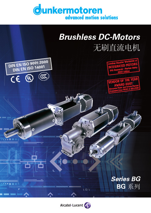
D I NE N I S O9001:2000D I N EN I S O 14001Foreword / 前言To Our Valued Customers,Alcatel-Lucent Dunkermotoren is a world class leader in high quality motion control solutions to meet the ever increasing demands for cost effective and reliable drive solutions.Our comprehensive product range offers the flexibilityto provide customized solutions as well as standardized components.The catalog represents Dunkermotoren´s years of engineering excellence.The Dunkermotoren Team will continue to utilize our outstanding engineering and industrial capabilities to meet the requirements helping you to succeed.Wishing you great success in your business.Nikolaus GräfGeneral Manager 致我们尊敬的客户,阿尔卡特-朗讯旗下的德恩科电机是世界一流的运动控制领域的领先制造商,它提供的优质的传动控制解决方案,满足了客户对成本和可靠性日益增长的的需求。
我们的产品范围包括各种类型的产品,因此具有灵活性;除了提供标准化的部件,还提供用户化的解决方案。
施耐德电气TeSys Giga系列控制设备与保护设备产品目录说明书

中国版TeSysTeSys 控制设备 – Giga 接触器TeSys 保护设备 2021 产品目录TeSys 控制设备 – Giga 接触器.............................简介............................................................................说明............................................................................产品参考....................................................................设计人员技术数据...................................................TeSys 保护设备 – Giga 电子过载继电器............简介............................................................................说明............................................................................产品参考....................................................................设计人员技术数据...................................................TeSys Giga 系列 – 设备选型.................................适用于各种应用的Giga 接触器..............................目录2610122127282930313550TeSys 控制设备 – Giga 接触器 TeSys 保护设备 – Giga 热过载继电器智能起动 智能运行TeSys™电动机控制设备首款BAR TeSys D首款三合一TeSys DGiga 接触器Giga 热过载继电器产品参考 - 编码原则Giga 接触器Giga 接触器Giga 接触器 - 简介Giga 接触器 - 简介Giga接触器的独特设计可以满足要求严苛的大功率应用的普遍要求:• 符合多种标准以满足全球需求 • 在严酷环境中的长使用寿命Giga 接触器 - 简介Giga 接触器 - 简介Giga 接触器 - 说明Giga 接触器 - 说明先进的接触器控制• 电子控制模块提供 48V-500V 的宽电压交/直流线圈控制电压,因此可以完美适配现有和新的应用场景。
D6X(Chinese)

二次保护专用的D6装置及二次保 护专用的D6电子零件
2006年 4月6日 TF R&D 前田 宪之
2
二次保护专用装置种类
有三种装置适用于二次保护
D6X FAM(UMI) SFH(SC)
4 5 1.7t
6.2 6.2 2.0t
3.2 5.4 1.35t
3
D6X的构造
陶瓷盖 熔断器 陶瓷基座 电阻膜
SEFUSE D6X
○○
8
二次保护运作
D6装置能够用极少的能量使二次保护运作
D6X 最低功力使二次保护动作 (-5℃/我们的测试结果) 1.4W FAM 2.3W SFH-1212A 4.0W
使用SFH运作二次保护需要较高功力。这意味着不需要 大容量的驱动FET。
O peration tim e(sec.) 80 70 60 50 40 30 20 10 0 0 1 2 3 4 5 6 7 Wattage(W) 8 9 10 11 12 -5℃ 25℃ 50℃
Current(A) 16 Ave. Max. Min. σ 38.6 45.0 29.0 6.3 20 11.8 15.4 9.8 2.4 30 3.2 3.8 2.7 0.5 50 0.674 0.730 0.610 0.050 75 0.310 0.370 0.250 0.049 100 0.055 0.063 0.047 0.007 150 0.018 0.020 0.015 0.002 180 0.010 0.013 0.008 0.001
150
FAM 135±5℃ 8A
SFH-1212A 非温度熔断器 12A
136±3℃ 12A
140 surface temp.(℃) 130 120 110 100 0 2 4 6 8 CurrentA) 10 12
飞龙 wi
持续电流(散热良好)瞬间电流(散热良好)BEC尺寸(供参考)重量(供参考)20A 30A 40A 60A 30A 40A 55A 80A 锂电池型号79g 35g 36g 76g 49x23.5x13.5mm 65.5x34x21mm● 反推功能,支持飞行过程中切换电机正反向,达到减速目的(WinDragon wifi 80-130A 支持此功能)。
2-4S 2-4S 2-6S 2-6S 8.4V/7.4V/6V/5V ,5A 80A 100A 119g 2-6S 100A 120A 125g 2-6S 130A150A130g82.5x39.5x23.5mm2-6S航模无刷电子调速器WinDragon wifi 130AWinDragon wifi 100A WinDragon wifi 80A WinDragon wifi 60A WinDragon wifi 30A WinDragon wifi 40A WinDragon wifi 20A 8.4V/7.4V/6V/5V ,5A 8.4V/7.4V/6V/5V ,5A 8.4V/7.4V/6V/5V,5A8.4V/7.4V/6V/5V ,5A 82.5x39.5x23.5mm 82.5x39.5x23.5mm 65.5x34x21mm 49x23.5x13.5mm 02 产品规格04 操作说明1.正常工作模式2.油门行程设定3.通过遥控器进行参数编程设定推荐使用Flycolor Wi-Fi Trans 通过Flycolor App 进行参数编程设定。
另外可通过编程卡进行参数编程设定1. 刹车: [1] 无刹车 [2]软刹车 [3]重刹车 [4]很重刹车 (出厂默认值为无刹车)2.电池类型: [1]LiPo(锂电) [2] NiCb/NiMh(镍氢/镍隔) (默认值为Li Po )3.低压保护阈值:低/中/高 [1] 2.8V [2]3.0V [3]3.2V ;默认值为中(3.0V)对于Ni-xx电池组:低/中/高中止电压是电池组初始电压值的50%/65%/75%对于Li-xx电池组:可自动计算电池数量,除了确定电池 类型外无需用户设置。
ADS807中文资料

12位,采样频率53兆的A/D转换器一、特点:1.无杂散动态范围:输入频率为10MHz时为82dB。
2.高信噪比:67.5dB(2v p-p),69dB(3V p-p)。
3.低功率:335mW。
4.有内部或外部参考5.低微分非线性:0.5LSB。
6.输入范围灵活:2V p-p到3V p-p。
7.28管脚封装二、应用:1.处理过程中的通信2.通信基站3.测试装备4.医疗成像5.视频数字化D数字化三、描述:ADS807是一个高速,宽动态范围,12位通道的数模转换器(A/D)。
这种数模转换器具有高带宽的跟踪和保持特性,而这种特性在奈奎斯特速率的附近表现出了良好的杂散性。
这种跟踪和保持特性的差分本质和A/D转换电路使偶次谐波最小化并且拥有良好的抗共模干扰能力。
而这种跟踪和保持特性一直具有直到信号结束。
ADS807在没有任何外部参考电路情况下,转换器的满量程都是可以使用的。
而内部的参考电路不支持低驱动,且内部的参考电路可以用来改善在多通道系统中的跟踪特性。
ADS807提供了一个超量程指示标志用来指示超出转换器输入满量程的输入信号,这个标志可以用来减少前端增益控制电路的增益。
且其存在一个输出使能管脚允许在PC板上实现复用和可测性。
ADS807采用数字误差校正技术,为需要图像处理的场合提供优良的差分线性。
绝对最大额定值:注意:列在上表“绝对最大额定值”中的这些重要参数可能对装置设备产生永久性的伤害。
长时间使用在绝对最大值的这种情况下可能会影响设备的可信度。
四、静电放电敏感度这个综合电路可能被ESD破坏。
TI公式推荐所有的综合电路要与适当的预防措施配合使用。
不遵守适当的处理和安装程序,可能会造成伤害。
ESD造成的破坏有很多,小到微弱的性能下降,大到整个装置的破坏。
精密的综合电路对这些破坏会更敏感,因为非常小的参数改变都可能引起装置不能满足其发布的规范。
包装/订购信息注意:(1)对于大部分当前的规范和包装信息查询我们的网站。
- 1、下载文档前请自行甄别文档内容的完整性,平台不提供额外的编辑、内容补充、找答案等附加服务。
- 2、"仅部分预览"的文档,不可在线预览部分如存在完整性等问题,可反馈申请退款(可完整预览的文档不适用该条件!)。
- 3、如文档侵犯您的权益,请联系客服反馈,我们会尽快为您处理(人工客服工作时间:9:00-18:30)。
S-80733AN S-80733AN-DX-X S-80733SN-DX-X S-80734AN S-80734AN-DY-X
S-80735AN S-80735AN-DZ-X S-80735SN-DZ-X S-80736AN S-80736AN-D0-X S-80737AN S-80737AN-D1-X S-80738AN S-80738AN-D2-X S-80739AN S-80739AN-D3-X
S-80740AL S-80740AL-A4-X S-80740SL-A4-X S-80740AH S-80740AH-B4-X S-80740AN S-80740AN-D4-X S-80740SN-D4-X S-80741AL S-80741AL-A5-X S-80742AL S-80742AL-A6-X S-80742SL-A6-X S-80743AL S-80743AL-A7-X S-80744AL S-80744AL-A8-X S-80741AN S-80741AN-D5-X
S-80719AN S-80719AN-DG-X S-80719SN-DG-X
S-80720AN S-80720AN-DH-X S-80720SN-DH-X
S-80721AN S-80721AN-DJ-X S-80721SN-DJ-X S-80722AN S-80722AN-DK-X
S-80723AN S-80723AN-DL-X S-80723SN-DL-X
元器件交易网
drain and CMOS output (active “H” and “L”), both of which have va product lineups. This series features much lower current consum and higher detection voltage accuracy than the S-805 Series. S miniature package is added for the S-807 Series, the S-807X Series. This small SOT-23-5 style package allows the design shrink the size of his finished product. Electrical specs for th 807XXSX Series are the same as the standard S-807 Series. O forms of the S-807XXSX Series are Nch open-drain and CMOS a “L”.
元器件交易网
Contents
Features........................................................... 1 Applications ..................................................... 1 Pin Assignment................................................ 1 Block Diagram ................................................. 2 Selection Guide ............................................... 3 Output Configurations...................................... 4 Advantage over the S-805 Series.................... 5 Absolute Maximum Ratings............................. 6 Electrical Characteristics ................................. 7 Test Circuits................................................... 23 Technical Terms ............................................ 24 Operation ....................................................... 26 Dimensions.................................................... 28 Taping............................................................ 29 Magazine Dimensions ................................... 31 Markings ........................................................ 32 Characteristics............................................... 33 Measuring Circuits ......................................... 36 Application Circuit Examples ......................... 37 Notes ............................................................. 39 Frequently Asked Questions......................... 40
S-80728AN S-80728AN-DR-X S-80728SN-DR-X S-80729AN-DS-X
S-80730AN S-80730AN-DT-X S-80730SN-DT-X S-80731AH S-80731AH-BV-X S-80731AN S-80731AN-DV-X S-80732Atures
• Ultra-low current consumption 1.0 µA typ. (VDD=4.5 V) • High-precision detection voltage ±2.4% • Wide operating voltage range 1.0 to 15 V • Good hysteresis characteristics 5% typ. • Wide operating temperature range -30°C to+80°C • 3 output forms : Nch open-drain, CMOS output active H , active L • TO-92, SOT-89-3 and SOT-23-5 package
Pin Assignment
(1) TO-92 1 OUT 2 VDD 3 VSS (2) SOT-89-3 Top view 1 OUT 2 VDD 3 VSS
1 1 1 2 3 2 3 2 3
(3) SOT-23-5 Top view
5 4
1 OUT 2 VDD 3 VSS 4 5 NC NC
S-80719AL S-80719AL-AG-X S-80719SL-AG-X S-80720AL-AH-X S-80720SL-AH-X S-80721AL S-80721AL-AJ-X S-80722AL S-80722AL-AK-X S-80723AL S-80723AL-AL-X S-80723SL-AL-X S-80724AL S-80724AL-AM-X S-80725AL S-80725AL-AN-X S-80725SL-AN-X S-80726AL-AP-X S-80727AL S-80727AL-AQ-X S-80727SL-AQ-X S-80728AL-AR-X S-80728SL-AR-X S-80729AL S-80729AL-AS-X S-80730AL S-80730AL-AT-X S-80730SL-AT-X S-80731AL S-80731AL-AV-X S-80732AL S-80732AL-AW-X S-80732SL-AW-X S-80733AL S-80733AL-AX-X S-80733SL-AX-X S-80733AH S-80734AL S-80734AL-AY-X S-80735AL S-80735AL-AZ-X S-80735SL-AZ-X S-80736AL-A0-X S-80737AL S-80737AL-A1-X S-80738AL S-80738AL-A2-X S-80739AL S-80739AL-A3-X S-80721SL-AJ-X
S-80742AN S-80742AN-D6-X S-80742SN-D6-X S-80743AN S-80743AN-D7-X
1.9 V±2.4%
0.095 0.1 0.105 0.11 0.115 0.12 0.125 0.13 0.135 0.14 0.145 0.15 0.155 0.16 0.165 0.17 0.175 0.18 0.185 0.19 0.195 0.2 0.205 0.21 0.215 0.22
Applications
• • • • • Battery checker Battery backup for memories Power failure detector Reset for microcomputer Store signal detector for nonvolatile RAM
S-80724AN S-80724AN-DM-X S-80724SN-DM-X
S-80725AH-BN-X S-80725AN S-80725AN-DN-X S-80725SN-DN-X S-80726AN S-80726AN-DP-X