中国2011年9月消费者物价指数又升6.1% 人行货币政策很难进入宽松
海尔LE42A700P节能电视产品说明书
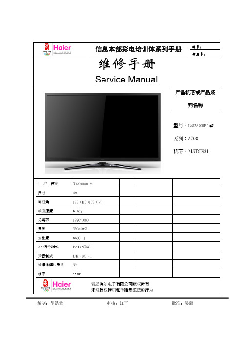
编号:信息本部彩电培训体系列手册专用号:维修手册Service Manual产品机芯或产品系列名称型号:LE42A700P节能系列:A700机芯:MST6I9811.屏、模组 T420HB01 V1尺寸 42可视角 178(H)/178(V)响应速度 6.5ms分辨率 1920*1080亮度 360cd/m2对比度 3500:12.信号制式 PAL\ NTSC声音制式 DK、BG、I流媒体模块型号 无功率 110W青岛海尔电子有限公司版权所有未经授权拷贝和传播是犯法的行为编制:胡浩然审核:江平批准:吴疆目录CONTENT项目 页码 项目 页码 1、规格 2 12.3 机芯接口定义 28 1.1 产品外观图 2 12.4 电源视图 29 1.2 产品特性 2 13、典型故障及解决措施、常见问题咨 311.3 产品先进技术 2 13.1 简要故障判定 322、 产品功能及主要特点 313.1H320P系列新增功能简要说明323、 产品衍生关系 5 13.2 常见故障现象及排除 334、 产品命名方式 5 14、安装和拆卸艺 345、产品使用说明及产品改进介绍、检测工具 615、爆炸图及明细 36 5.1仪器、仪表、操作工具的配置 616、结构规格书 375.2基板检查方法 6 17、各主要检测点的电压 386、使用者的警告 718、机芯板主要元件功能 39 6.1 警告 719、产品主要模块专用号 40 6.2 注意 720、机器软件升级调试说明 41 6.3 供电电源 76.4 使用场所 76.5 清洁 76.6 注意事项 77、案例预防措施、产品使用及日常维护保养知识 87.1 注意事项 87.2 误区 88、产品主要技术参数 99、原理图及接线图 109.1 原理图 119.2 接线图 2310、机器具体控制、工作原理及参数 2411、机器透视图与平面 2612、各模块视图、接口定义 2712.1 屏接口定义 2712.2 机芯板视图 281、产品外观结构特征(含外观图)1.1 LE42A700P节能外观图后名牌图标准遥控器端子图侧端子下端子110W HTR-D3E端子1.2 ☆机器特性1、1920*1080高分辨率;2、时尚A700窄边框外观。
SN93370_DSTO_A1

1
General Description
SONiX SN93370 series is a wireless video/audio processor. It supports one-way video, two-
way audio and two-way command transmission through proprietary Wi-Fi. The system provides strong coexistence and anti-interference with other wireless device. Besides point-to-point transmission, SN93370 also supports 4T1R transmission and broadcast. It is possible to display image from quad cameras on a LCD panel. SN93370 is a turnkey solution for all wireless video applications. To reduce the overall BOM cost, it integrates mono audio ADC, microphone pre-amplifier, mono audio DAC and USB 2.0 Host/Device interface. It built-in 32bit ARM Cortex™-M0 processor which can operating up to 160MHz and provide powerful CPU performance for firmware execution. Otherwise it’s also built-in a powerful ISP (image signal processor) to produce good quality image. For LCD display, it can support max. 800x600 resolution 7” LCD panel for Vehicle rear view camera/monitor application. SONiX also open SN93370 firmware SDK (in C language), PC application and hardware design guidelines for customers. It is very easy to customize and develop.
ANSI-ESD+STM9.1-2006(footwear)

ANSI/ESD STM9.1-2006Reaffirmation of ANSI/ESD STM9.1-2001For the Protection of Electrostatic Discharge Susceptible ItemsFootwear – Resistive Characterization(not to include heel straps and toe grounders)Electrostatic Discharge Association 7900 Turin Road, Bldg. 3 Rome, NY 13440 An American National Standard Approved October 5, 2006ANSI/ESD STM9.1-2006ESD Association Standard for the Protection of Electrostatic Discharge Susceptible Items –Footwear – Resistive Characterization(not to include heel straps and toe grounders)Approved June 11, 2006 ESD Association®ANSI/ESD STM9.1-2006CAUTION NOTICEESD Association standards and publications are designed to serve the public interest by eliminating misunderstandings between manufacturers and purchasers, facilitating the interchangeability and improvement of products and assisting the purchaser in selecting and obtaining the proper product for his particular needs. The existence of such standards and publications shall not in any respect preclude any member or non-member of the Association from manufacturing or selling products not conforming to such standards and publications. Nor shall the fact that a standard or publication is published by the Association preclude its voluntary use by non-members of the Association whether the document is to be used either domestically or internationally. Recommended standards and publications are adopted by the ESD Association in accordance with the ANSI Patent policy. Interpretation of ESD Association Standards: The interpretation of standards in-so-far as it may relate to a specific product or manufacturer is a proper matter for the individual company concerned and cannot be undertaken by any person acting for the ESD Association. The ESD Association Standards Chairman may make comments limited to an explanation or clarification of the technical language or provisions in a standard, but not related to its application to specific products and manufacturers. No other person is authorized to comment on behalf of the ESD Association on any ESD Association Standard.DISCLAIMER OF WARRANTIESThe contents of ESDA’s standards and publications are provided “as-is,” and ESDA makes no representations or warranties, express or implied, of any kind with respect to such contents. ESDA disclaims all representations and warranties, including without limitation, warranties of merchantability, fitness for particular purpose or use, title and noninfrigement. Disclaimer of Guaranty: ESDA standards and publications are considered technically sound at the time they are approved for publication. They are not a substitute for a product seller’s or user’s own judgment with respect to any particular product discussed, and ESDA does not undertake to guaranty the performance of any individual manufacturers’ products by virtue of such standards or publications. Thus, ESDA expressly disclaims any responsibility for damages arising from the use, application or reliance by others on the information contained in these standards or publications. Limitation on ESDA’s Liability: Neither ESDA, nor its members, officers, employees or other representatives will be liable for damages arising out of or in connection with the use or misuse of ESDA standards or publications, even if advised of the possibility thereof. This is a comprehensive limitation of liability that applies to all damages of any kind, including without limitation, loss of data, income or profit, loss of or damage to property and claims of third parties.Published by: Electrostatic Discharge Association 7900 Turin Road, Bldg. 3 Rome, NY 13440 Copyright © 2006 by ESD Association All rights reserved No part of this publication may be reproduced in any form, in an electronic retrieval system or otherwise, without the prior written permission of the publisher. Printed in the United States of America ISBN: 1-58537-117-3ANSI/ESD STM9.1-2006(This foreword is not part of ESD Association Standard Test Method STM9.1-2006)FOREWORD This standard is intended to provide a test method for evaluating the resistance of static control footwear. This standard does not include heel straps, toe grounders and booties. This standard is limited to defining procedures for measuring the electrical resistance of footwear only and does not address electrical resistance through a person or in combination with floor materials. A common source of electrostatic charge in a work environment is the separation of the foot from the floor, resulting in the generation of electrostatic charge that can accumulate on personnel. The effect of this generation and accumulation can be minimized by the appropriate selection of footwear. To effectively control electrostatic charges, footwear must be used in conjunction with ESD floors or floor materials as defined in ANSI/ESD S7.1. Static control footwear may also pose an electrical hazard unless properly designed and worn in appropriate environments. The test method described in this document will not guarantee electrical hazard reduction. This standard was originally designated ESD S9.1-1995 and was approved on June 5, 1995. Standard Test Method ANSI/ESD STM9.1-2001 was a reaffirmation and redesignation of ESD S9.1-1995 and was approved on February 4, 2001. Standard Test Method ANSI/ESD STM9.1-2006 is a reaffirmation of ANSI/ESD STM9.1-2001 and was approved on June 11, 2006. All documents were prepared by the 9.0 Footwear Subcommittee. At the time the S9.1-1995 version was prepared, the 9.0 Footwear Subcommittee had the following members: Peter Freeman Ben Baumgartner Lt. Victoria L. Ambuehl Hewlett Packard Lockheed USAF, Chair Steve Gerken USAF Paul Isenberg H.H. Brown Shoe Co. Don Stella Iron Age Larry Burich Lockheed Ken Dille Red Wing Shoe Co. Ron Gibson Celestica Erling Krog-Jensen Ericsson Telecom AB Anna Maria Steritti David Howlett HY-Test Alan Peters Lehigh Safety Shoe Co. Wayne Tan Advanced Micro Devices Sheryl Zayic BoeingThe following individual made significant contributions to this document: Sharon KaminskasiANSI/ESD STM9.1-2006At the time the STM9.1-2006 version was prepared, the 9.0 Footwear Subcommittee had the following members: Brent Beamer 3M Dale Parkin, Chair IBM Mark Fancourt Lehigh Safety Shoe Co. Kevin Duncan Seagate TechnologyiiANSI/ESD STM9.1-2006TABLE OF CONTENTS1.0 PURPOSE, SCOPE AND APPLICATION.............................................................................. 1 1.1 PURPOSE ............................................................................................................................. 1 1.2 SCOPE ................................................................................................................................. 1 1.3 APPLICATION ........................................................................................................................ 1 2.0 REFERENCED DOCUMENTS ............................................................................................... 1 3.0 DEFINITION OF TERMS ........................................................................................................ 1 4.0 PERSONNEL SAFETY........................................................................................................... 1 5.0 TEST METHOD....................................................................................................................... 2 5.1 APPARATUS REQUIREMENTS ................................................................................................. 2 5.1.1 Resistance Measuring Apparatus (Meter) ................................................................... 2 5.1.2 Electrodes .................................................................................................................... 2 5.1.3 Weight .......................................................................................................................... 2 5.1.4 Environmental Test Chamber ...................................................................................... 2 5.1.5 Calibration Requirements ............................................................................................ 2 5.2 TEST PROCEDURE / CONDITIONING ........................................................................................ 2 5.2.1 Specimen Pre-conditioning .......................................................................................... 2 5.2.2 Test Configuration........................................................................................................ 3 5.2.3 Resistance Measurement Procedure........................................................................... 3 5.2.4 Reporting of Test Results ............................................................................................ 4 FIGURES Figure 1. Test Setup ....................................................................................................................... 5 Figure 2. Test Result Form............................................................................................................. 6 ANNEX A ........................................................................................................................................ 7iiiESD Association Standard Test MethodANSI/ESD STM9.1-2006ESD Association Standard Test Method for Protection of Electrostatic Discharge Susceptible Items – Footwear – Resistive Characterization 1.0 PURPOSE, SCOPE AND APPLICATION 1.1 Purpose This standard provides a test method to measure the electrical resistance of static control footwear. 1.2 Scope This standard relies on electrical resistance measurements utilizing common electrical instruments to provide a means of evaluating footwear. This standard excludes heel straps, toe grounders, etc. 1.3 Application This standard is intended to be used in the qualification of static control footwear. 2.0 REFERENCED DOCUMENTS ESD ADV 1.0, ESD Association Glossary of Terms1 ANSI/ESD S7.1, Floor Materials – Characterization of Materials1 ANSI/ESD S20.20, Development of an Electrostatic Discharge Control Program for – Protection of Electrical and Electronic Parts, Assemblies and Equipment (Excluding Electrically Initiated Explosive Devices)1 ASTM D-257, Standard Test Methods for D-C Resistance or Conductance of Insulating Materials2 3.0 DEFINITION OF TERMS The following definition shall apply for the purposes of this standard in addition to those specified in the ESD Association Glossary of Terms: Static Control Footwear (Footwear). Coverings for the human foot that have properties to dissipate static charge when used in conjunction with a static control floor or floor surface as defined in ANSI/ESD S7.1. 4.0 PERSONNEL SAFETY 4.1 The procedures and equipment described in this document may expose personnel to hazardous electrical conditions. Users of this document are responsible for selecting equipment that complies with applicable laws, regulatory codes and external and internal policy. Users are cautioned that this document cannot replace or supercede any requirements for personnel safety. The ultimate responsibility for personnel safety resides with the end user of this document. Ground Fault Circuit Interrupters (GFCI) and other safety protection should be considered wherever personnel might come into contact with electrical sources. Electrical hazard reduction practices should be exercised and proper grounding instructions for the equipment must be followed when performing these tests.1 2ESD Association, 7900 Turin Road, Bldg. 3, Rome, NY 13440-2069, 315-339-6937 American Society for Testing and Materials (ASTM), 1916 Race Street, Philadelphia, PA 19103-1187, 215-299-54001ANSI/ESD STM9.1-20064.2 The resistance values obtained using the test method described in this document are not to be used to define the relative electrical hazard reduction afforded by footwear. 5.0 TEST METHOD This section describes the test method for measuring the electrical resistance between the inner and outer sole of footwear prior to wearing. 5.1 Apparatus Requirements 5.1.1 Resistance Measuring Apparatus (Meter) The measurement apparatus, called the meter, whether it is a single meter or a collection of instruments, that are capable of the following: The meter shall have circuit voltage of 100 volts (± 5%) DC while under load for measurements of 1.0 x 10⁶ ohms and above. Both test leads shall be isolated from ground. 5.1.2 Electrodes The positive electrode shall consist of a piece of aluminum foil. It shall uniformly contact the maximum amount of the surface area achievable on the inner sole of the footwear under test. The aluminum foil shall be replaced for each new test cycle, or when torn. The negative electrode shall consist of a stainless steel plate larger than the bottom of the footwear, which is placed on an insulative surface. The resistance of the insulative surface shall be greater than 1 x 10¹³ when measured per ASTM D-257. 5.1.3 Weight Twenty-five pounds (11.35 kg) of metal shot (# 6 or finer) in a bag or bags sufficiently flexible so that when filled with shot they shall conform to inside of the footwear. 5.1.4 Environmental Test Chamber An enclosed chamber capable of controlling relative humidity to 12% RH (± 3%) and 50% RH (± 5%), and temperature to 23 °C (± 3 °C). The humidity indication instrumentation shall be accurate to ± 3% RH in the operation range and traceable to national standards, such as National Institute of Standards and Technology (NIST) in the United States, or to international standards. 5.1.5 Calibration Requirements The test equipment used shall be calibrated periodically in accordance with the manufacturers' recommendations, with a maximum of one year between calibrations. Calibration shall be traceable to national standards, such as NIST in the United States, or to international standards. 5.2 Test Procedure / Conditioning 5.2.1 Specimen Pre-conditioning 5.2.1.1 Cleaning The bottom and inner sole of the specimen shall be wiped with a dry cloth to remove dust. The negative electrode shall be cleaned with a minimum 70% isopropanol-water solution.2ANSI/ESD STM9.1-20065.2.1.2 Humidity Conditioning Test shall be conducted at humidities specified below. 5.2.1.2.1 Low Humidity After cleaning, the samples shall be placed in an environmental chamber preset to 12% (± 3%) relative humidity and 23 °C (± 3 °C). Pre-conditioning of the samples shall be a period of at least 72 hours. 5.2.1.2.2 Moderate Humidity After cleaning, the samples shall be placed in an environmental chamber preset to 50% (± 3%) relative humidity and 23 °C (± 3 °C). Pre-conditioning of the samples shall be a period of at least 72 hours. 5.2.2 Test Configuration The negative electrode shall be placed on the insulative surface described in 5.1.2 and electrically connected to the negative sensing lead of the meter. The aluminum foil shall be inserted into the footwear ensuring that uniform contact with maximum amount of the inner sole is achieved. Fill the footwear with the flexible bags of shot, ensuring that the shot conforms to the footwear. Since footwear styles and sizes vary, it will be necessary to place the excess shot over the top of the footwear. The footwear shall be placed on the negative electrode such that no part of the footwear overhangs the edge. No part of the shot bags shall touch the negative electrode. Connect the positive source lead of the meter to the aluminum foil. Resistance testing shall be conducted in the environmental chamber (Figure 1). NOTE: The resistance of the support surface will not affect the electrical resistance measurement of the sample under test. 5.2.3 Resistance Measurement Procedure 5.2.3.1 Clean footwear per 5.2.1.1. 5.2.3.2 Condition footwear per 5.2.1.2.1 (Low Humidity). 5.2.3.3 Set up the test configuration per 5.2.2. Set the resistance meter to 100 volts DC. Apply the test voltage and record the resistance of the footwear after the reading has stabilized. Remove test voltage and electrode connection. 5.2.3.4 Clean footwear per 5.2.1.1. 5.2.3.5 Condition footwear per 5.2.1.2.2 (Moderate Humidity). 5.2.3.6 Repeat 5.2.3.3 for all samples.3ANSI/ESD STM9.1-20065.2.4 Reporting of Test Results Report all resistance values in ohms. Also report test date/time, test equipment used, environmental pre-conditioning time, temperature, relative humidity, footwear identification and the location of the test. Figure 2 is provided as an example. NOTE: Refer to ANSI/ESD S20.20 for electrical resistance limit for static control footwear. NOTE: It is recognized that some hygroscopic materials (such as, but not limited to, leather) may have results that fluctuate and do not remain within a specified minimum or maximum resistance range as the environmental conditions change.4ANSI/ESD STM9.1-20065 Figure 1. Test SetupResistanceMeasuringApparatusSteel PlateCut away view of foilinside shoe.Cut away view of sockand foil inside shoe.ANSI/ESD STM9.1-20066ESD FOOTWEAR TESTOperator: Test Method: Pre-conditioning Test Conditions Time: Duration: Date: Temperature: Location: % RH:TEST RESULTSFootwear IDResistance (ohms)Figure 2. Test Result FormANSI/ESD STM9.1-20067ANNEX A Fabrication of Shot BagNumber 6 shot is fine and may fall through the fabric weave, especially knit socks. Constructing 2 to 3 inch (4.68 – 7.02 cm) tubes from a tightly woven fabric is recommended.Use of 25 lbs (11.35 kg) of weight.After considerable research it was determined that while weight is a variable when measuring the resistance of footwear, after 25 lbs (11.35 kg) there is no significant difference in the electrical resistance readings. Therefore 25 lbs (11.35 kg) of weight is required.Number 6 shot was chosen because it would most easily conform to the inside surface of any footwear size and lends itself to even weight distribution.。
Aptiv 10949001 连接系统 - 型号A到型号D的视图和说明书

7
6
SYMBOL DEFINITION
SAFETY/COMPLIANCE K S/C CHECKPOINTS
FIT/FUNCTION K F/F CHECKPOINTS
TOTAL ON
DRAWING
1
LAST NO.
USED
1
A DIMENSION WITHOUT AN INSPECTION REPORT SYMBOL DOES NOT REQUIRE INSPECTION. IT MAY BE
27
6.05 0.4
XXXXXXX DDDY-XX
52772-1A
CPA (PRE STAGE) - SEE CHART
SEALED ASSEMBLY VIEW
(PARTIALLY SEALED) SHIPPED WITHOUT END SEAL AND RETAINER
11
10
9
8
KEY PRODUCT CHARACTERISTICS
18. MVL SUPPLIER CODE: 52772 OR 52772H
9. DIRECT CONNECT DRAWING NO. MVL G36014 (CHRYSLER 04707029).
10. TEST METHOD PER CHRYSLER PERFORMANCE SPEC# SAE/USCAR-2 REV 5. CONNECTOR ENGAGE & DISENGAGE WITH LATCH DEPRESSED FORCE NOT TO EXCEED 142N FOR THIS SYSTEM
7X 1.9 PLR (PRE-STAGE) - SEE CHART
2X 0 2X 15.75 2X 10.5 2X 5.25
Leviton ATLAS-X1 Cat 6A Component-Rated UTP QUICKP

Page 1 of 2APPLICATIONThe ATLAS-X1 Cat 6A Component-Rated UTP QUICKPORT Jack supports 10GBASE-T networks. The jack is part of a complete ATLAS-X1 Cat 6A UTP system, ideal for the most demanding mission-critical network applications. The connector supports emerging technologies and will easily adapt to network trends.SPECIFICATIONThe jack shall meet or exceed the requirements for channel and component-level electrical transmission performance as described in ANSI/TIA-568.2-D (Cat 6A), ISO/IEC11801-1 (Class E A ), and EN 50173-1 (Class E A ). The jack shall be compliant with ANSI/TIA-1096-A, c(UL)us Listed, and be independently verified for electrical transmission performance and power delivery. The jack body shall be made of die-cast zinc and all plastic components shall be made of high-impact, fire-retardant plastic rated UL 94V-0. The jack shall support tool-free termination and re-termination and shall not require a specialized termination tool. The jack wiring shall be universal to accommodate T568A and T568B wiring schemes. The jack shall be available in 13 colors; more than established by the ANSI/TIA-606-C standard. The jack shall be offered in standard and shuttered styles and select jacks shall be supplied with interchangeable icons. The jack shall be compliant with IEEE 802.3 PoE Type 1, 2, 3, 4 (100 watts max).DESIGN CONSIDERATIONS• Use in any QUICKPORT™ housing to support Cat 6A UTP connectivity in surface-mount, flush-mount, or modular furniture outlets and field-configurable panels• Can be used in conjunction with other QUICKPORT snap-in modules for voice/data/video applications over UTP , coax, and fiber• To identify ports, use different colored modules andicons for each application (full selection of ANSI/TIA-606 compatible colors, 13 available)• Robust housing and shutter protects the jack in harsh environmentsATLAS-X1™ Cat 6A Component-Rated UTP QUICKPORT™ Jack6AUJK-xx6, ICONS-ICxFEATURES• Independently tested and guaranteed to exceed all component, permanent link, and channel margins• Patented Retention Force Technology™ (RFT) protects against tine damage and increases system longevity • For Power over Ethernet, RFT maintains contact force between plug and jack, preventing arcing from intermittent disconnects• Unique design supports tool-free termination andre-termination and requires no specialized termination tool • Short jack design supports a wider range of applications (e.g. shallow boxes, enclosures, bend radius, etc.)• Terminates from 26 to 22 AWG solid or stranded conductors for use on various cable types• Robust IDCs can withstand 20 re-termination cycles and jack contacts are tested for 750 plug-mating cycles to ensure system longevity• Available in 13 ANSI/TIA-606-C compatible colors • Tested and approved for use in air-handling spaces (plenum rating) in accordance with UL Standard 2043• Select jacks available with interchangeable icons (voice, data, A/V, blank) for easy ID• Jack with internal shutter protects against dust and debris • Solid metal body dissipates 53% more heat than plastic, minimizing damage from excess heat in PoE applications • Tine geometry prevents arcing damage where plug and jack make contactSTANDARDS & REGULATIONS• ANSI/TIA-568.2-D (Cat 6A)• ISO/IEC 11801-1 (Cat 6A)• EN 50173-1 (Cat 6A)• ANSI/TIA-1096-A (formerly FCC Part 68)• IEC 60603-7 (includes IEC 60512-5-2)• IEC 60512-99-002• IEEE 802.3 PoE Type 1, 2, 3, 4 (100 watts max)• Cisco UPOE, UPOE+ (90 watts max)• Power over HDBaseT™ PoH (95 watts max)• c(UL)us Listed (UL 1863)• UL 2043 Plenum Certified • RoHS 3• ETL verified to meet the IEC 60512-99-002 standard for support of IEEE 802.3 Type 4 PoE (100 watt) applicationsCOUNTRY OF ORIGINUSA and Mexico (Contact Customer Service for details)6AUJK-xx6, ICONS-ICxUSANetwork Solutions Headquarters +1 (800) 722 2082 *******************Leviton Berk-Tek Cable : +1 (800) 237 5835 ************************Asia Pacific+852 3620 2602********************Canada+1 (800) 461 2002**********************Europe+44 (0) 1592 772124 **********************Latin AmericaMX: +52 (55) 2128 6286 LATAM: +52 (55) 2333 5963 *********************Middle East & Africa +971 (4) 247 9800 *******************NETWORK SOLUTIONS PRODUCTS ARE AVAILABLE WORLDWIDE IN OVER 100 COUNTRIES. VISIT US ONLINE AT /NS TO LEARN MORE.Page 2 of 2For further support information, visit /ns/support6AUJK-xx6, ICONS-ICx6AUJK-xx6, ICONS-ICxMECHANICAL SPECIFICATIONSDimensions:See belowMaterials: Jack Body: Die-cast zincSpring-Wire Contacts: High quality, copper-based alloy, plated with 50 microinches of gold for lowest contact resistance andmaximum life Temp. (Storage):Temp. (Installation): Temp. (Operating):Humidity (Max.):WARRANTY INFORMATIONFor Leviton product warranties, go to /ns/warrantyPART NUMBERDescriptionStandard Jack Jack with Shutter GREENPACK™12-Pack Standard Jack ATLAS-X1™ Cat 6A Component-Rated UTP QUICKPORT™ Jack, white 6AUJK-RW66AUJK-SW66AUJK-CW6ATLAS-X1 Cat 6A Component-Rated UTP QUICKPORT Jack, light almond 6AUJK-RT66AUJK-ST6—ATLAS-X1 Cat 6A Component-Rated UTP QUICKPORT Jack, ivory 6AUJK-RI66AUJK-SI6—ATLAS-X1 Cat 6A Component-Rated UTP QUICKPORT Jack, yellow 6AUJK-RY66AUJK-SY6—ATLAS-X1 Cat 6A Component-Rated UTP QUICKPORT Jack, orange 6AUJK-RO66AUJK-SO6—ATLAS-X1 Cat 6A Component-Rated UTP QUICKPORT Jack, crimson 6AUJK-RC66AUJK-SC6—ATLAS-X1 Cat 6A Component-Rated UTP QUICKPORT Jack, dark red 6AUJK-RR66AUJK-SR6—ATLAS-X1 Cat 6A Component-Rated UTP QUICKPORT Jack, purple 6AUJK-RP66AUJK-SP6—ATLAS-X1 Cat 6A Component-Rated UTP QUICKPORT Jack, blue 6AUJK-RL66AUJK-SL66AUJK-CL6ATLAS-X1 Cat 6A Component-Rated UTP QUICKPORT Jack, green 6AUJK-RV66AUJK-SV6—ATLAS-X1 Cat 6A Component-Rated UTP QUICKPORT Jack, gray 6AUJK-RG66AUJK-SG6—ATLAS-X1 Cat 6A Component-Rated UTP QUICKPORT Jack, black6AUJK-RE66AUJK-SE66AUJK-CE6ATLAS-X1 Cat 6A Component-Rated UTP QUICKPORT Jack, brown6AUJK-RB66AUJK-SB6—Green (V)Blue (L)Purple (P)Crimson (C)Dark Red (R)Orange (O)Yellow (Y)Black (E)Gray (G)Ivory (I)Light Almond (T)Brown (B)Color-matched icons (ICONS-ICx) can be ordered separately in 72-quantity packs.x = icon color。
09年3月份日照九州戴尔笔记本标准配置及价格表doc-4

37%
9,893.
27
笔记本
戴尔E6400 (14寸)
主板Intel(R) 45 Express芯片组/ CPU Intel酷睿2 P8400, 2.26GHz, 1066MHz, 3MB)/ 14.1" LED WXGA+ (1440X900) TrueLife(TM) / 2GB内存(1x2G) DR2 800MHz / 64G SSD固态硬盘2.5" / DVD刻录光驱/ 256MB独立显卡NVS 160M / Dell Wireless(TM) 1510无线网卡(802.11a/b/g/n 2X3)/ Windows vista Home SP1正版操作系统/指纹识别器/蓝牙/内置摄像头/背光键盘/原厂笔记本包和光电鼠标/ 6芯电池/ 65W电源适配器/内置调制解调器/黑色本
16231
43%
.9252
22
笔记本
戴尔E5400 (14寸)
主板Intel(R) 45 Express芯片组/ CPU Intel酷睿2P8600(2.40GHz 1066MHz 3M)/ 14.1"(1440 x 900)/2GB内存(1x2G) DR2 800MHz /250GSATA硬盘7200 RPM/ DVD刻录光驱/集成显卡/ Dell Wireless(TM) 1510无线网卡(802.11a/b/g/n 2X3)/双指点杆/蓝牙/原厂笔记本包和光电鼠标/ 6芯电池笔记本电池的质量保证期为一年/ /三年上门保修65W电源适配器/内置调制解调器/黑色笔记本
5699
8%
5300
4
笔记本
戴尔1330(13寸)
T6400/ 2G/250G / 128M 8400GS显卡/ 13.3”/ DVDRW/ 6蕊电池/无线/200万摄像头黑色笔记本
I-9 用户手册说明书

I-9 User Guide Online I-9 & E-VerifyProcessUpdated June 2023Table of ContentsOnline I-9 & E-Verify Process 2 I-9 Compliance 3 Section 1 – Employee Information 4 Accessing the System 11 New Hire Center 13 Section 2 – Employer Review 16 Photo Matching 22 Terminations 33 Special Circumstances 33Online I-9 and E-Verify ProcessAbout Electronic I-9s and E-Verify•Implemented to automate the process of documenting that each new employee is authorized to work in the United States•Complies with mandate from the Governor of Virginia to process all new hires and rehires through E-Verify•E-Verify allows employers to automatically determine eligibility of their employees to work in the United States•Online I-9 Management system is hosted by external vendor•Electronic I-9s are stored in a central database•Eliminates the need to complete a paper I-9 and submit to HRWhat is an I-9?• A form used to document verification of identity and employment eligibility of all employees (both citizen and non-citizen) hired to work in the United States after November 6, 1986•Required to comply with the Federal Immigration Reform and Control Act•Regulated by the U.S. Citizenship and Immigration Services (USCIS) division of Department of Homeland Securities (DHS)Some Penalties for Non-Compliance•Employers who violate the law may be subject to:o Civil fineso Criminal penalties (when there is a pattern or practice of violations)o Debarment from government contractso A court order requiring the payment of back pay to the individualdiscriminated againsto A court order requiring the employer to hire the individual discriminated against•More information is available at: /i-9-central/penaltiesI-9 ComplianceIs an I-9 Required?•Open Banner form PZII9HS for the employee•Does the employee have an E-Verify case number?o If NO, continue with I-9 processo If YES, open Banner form PWIEMPV•Review job start/end dates/last paid date•If there is a break in service or break in pay for more than one year, a new I-9 must be completed•For non-residents, the employment authorization documents could have changed - review carefully•Contact HR with questions if an I-9 is neededPWIEMPVTIPS: You can find the Last Paid Date on page PWIEMPVSection 1: Employee Information•Section 1 should be completed and signed by employee on or before the first day of work•Employee will receive two emails from **********************. One will have the link to the New Hire Center and the other will have the password to login. The password is only valid for the original login.*Please note, wage employees must have a job in Banner before they will be sent to the New Hire Center and receive these email*•Once logged in, employee will need to complete all forms in the New Hire Center before completing section 1 of the I9.Section 1:TIPS:•All fields are required EXCEPT:o Other Nameso Apt. Numbero Email Addresso Telephone Number•If the employee does not have a Middle Name, enter N/A•Foreign nationals without a Social Security number- check the “SSN Applied For”button below the Social Security number fieldTIPS:•Employee attests to citizenship•If number 4, An alien authorized to work until, is selected the new hire should indicate the “authorized to work until date” on the i9. The date should be listed on their form I-20, DS2019, or another form of work authorization.•If someone other than employee prepares section 1 on behalf of employee, thePreparer and/or Translator Certification must be completed•Click Continue to save•Review the data foraccuracy•Scroll to bottom of page•Employee signs the form by checking the attestation box•Employee’s initials must correspond to the name asit was keyed (not casesensitive)•If the employee hasmultiple first namesand/or last names, onlyenter the first, first nameinitial and the first, lastname initial•Click ContinueTIPS:•Print the receipt code page if section 2 will be completed by a remote completer. The remote completer will need the receipt number to pull up the I9.•New Hire will receive an email confirmation once Section 1 has been completed •Scroll to bottom of page to review acceptable documents to present for completingSection 2•Click continue to finish section 1TIPS:•List A document to prove identity and work authorization OR List B document to prove identity AND List C document to prove work authorization• A full list of acceptable documents can be found at https:///i-9-central/form-i-9-acceptable-documents•All documents must be original. Only exception is certified copy of birth certificate •All documents must be unexpired by the first day of work. For Foreign Nationals, Transfer Pending documents may not be used•Must present a document with a photo•Reminder – employee must present original documentation within three business days of starting workGetting access the I9 SystemFor employees needing access to the I9 system for processing purposes, departments need to complete the following steps:•Employer access only – for I9 access, complete the following steps:•Online Banner HR access request form on (https:///vt/prod/vtirm.irm_forms_main.entry) •Login and select Add/Change Administrative System Access•Enter employee’s ID and select Request additional access•Select Human Resources and check the Online I-9 option•Submit electronic form•Print copy for signature approval•Must be signed by employee AND dean, director, or department head•Send a signed copy to the HR Apps Team through the HR Dropbox (The dropbox link is located on )Completing Section 2 of the I9This section focuses on how to search for employees and complete section 2 of the I-9•Click on Login to New Hire CenterConsent to Information Release•Each time an I9 processor logs in, the Consent to Information Release screen will appear. Verify the VT Username and ID number, then click the SharebuttonNew Hire Center Welcome Screen•Click on Search Employee to verify all forms have been completed and Section 2 is ready to be completed•Enter First and Last Name, then press View•Verify Status says Document Complete - Waiting on Section 2 of I9•Click on the NameClick Complete I9•Verify the start date is the first day the employee began working. If the date listed is not the first day of physical work, please update this date.•Enter the VT ID. Do not include dashes•Visa type is not applicable to US Citizen•Select the document(s) presented by employee•Select documents from valid list of options provided in drop down list. The list provided will be based on the citizenship status indicated in Section 1•If employee is terminated before completing I-9, choose that option and continue•Click Continue to save•Examine documents and record verification information•Complete all fields provided•Click Continue to saveTIPS:•Fields may vary depending on documents presented•Click on Sample Document link to view valid examples of selected document type •Do not include dashes in Document number•If there is no Document number, include several zeros• Carefully review all information entered • Check the box stating you have read and agree with certification statement • Click Continue to saveE-Verify Status•Unique case number is assigned to I-9•I-9 verified against SSA and DHS databases•Receive initial status response within seconds•How to proceed depends on E-Verify status. One of the following messages will appear:o Employment authorized▪Employment authorized - with additional verification optional▪Employment authorized - with additional verification requested automaticallyo Photo matching requiredo Current I-9 is not eligible for verificationo SSA or DHS tentative non-confirmation; this status will be handled by the Central HR I9 Coordinators•Temporary initial responses, requiring more time or more steps include: o Initial verification not processed▪Review/Edit employee data (may indicate minor error/typo) o DHS verification in processo SSA or DHS continuanceo DHS referral to SSAo SSA/DHS case incomplete•I-9 wassuccessfullyadded•Next actiondepends onE-Verifyresponse•Always click“View CaseDetails” totakeappropriateaction•E-Verify has assigned a Case Number•Status at bottom of page shows Employment Authorized (If anything other than Employment Authorized or Manual Review is showing, please contact *********) •Case Resolved should be displayed at bottom of page•Logout or click Back to Compliance Center and proceed with another I-9Photo Matching•Required when employee presents any of the following eligibility documents: o U.S. Passport or Cardo I-551 Permanent Resident Card (green card)o I-766 Employment Authorization Document (EAD)•E-Verify requires I-9 administrators to match the photo provided with the one on file with the United States Citizenship and Immigration Services (USCIS)• A securely scanned copy of the photo document must be attached to the electronic I-9 as supporting documentation.•DO NOT ATTACH OTHER DOCUMENTS.Attaching Photos•Securely scan the image•Save the file with a name you will recognize•Attach the scanned image to the electronic I-9•Open the attached document to confirm legibility•Delete the file or encrypt it if retainedo Do not send any scanned documents to HRSECTION 2 – Uploading DocumentsTIPS:• Use List A to select US Passport or US Passport card, Permanent Resident Card, or Employment Authorization Document (EAD).• Attach both the front and back of the card. This can be attached as two separate documents• Click Continue to saveTIPS:• Examine the employee’s document(s) and record verification data • Enter Expiration Date (check box if there is not one)• Click Continue to saveTIPS:• Get started by uploading the image file• Select the Attach File link – Do not click on Upload I9. This will overwrite the currentI9 document in the fileTIPS:• Select document from list of valid options• Scroll to the bottom of the pageTIPS:• Select document from list of valid options• Be sure to use image files in one of the supported formats • Use the Choose File button to select from your computer • Click UploadTIPS:• An image of the attachment appears• Select Correct if this document does not have any errors • Select Incorrect if there are errors presentTIPS:• Notice theUploadStatus nowshows acheck mark• Press theFinishedbuttonTIPS:• E-Verify hascaught upand displaysthe PhotoMatchingstatus• Click viewcase detailsor scroll tothe bottom ofthe pageTIPS:• Verifylegibilityand closethe windowTIPS:• Click thePhotoMatchingbutton toproceed• Compare the photo shown to the photo on the ID cardSelect Yes:• If the photo on the document matches the photo on file• If there is no photograph in the database• Click Continue to proceedSelect No:• If the photo on the ID does not match the database• E-Verify response will be a Tentative Non-Confirmation• Notify *********• Click Continue to proceedSelect No Photo Displayed:• If not photo shows, click the No Photo Displayed button and click ContinueTIPS:• E-Verify has assigned a Case Number • Scroll to the bottom of the page• Make sure the case is closed• I-9 circumstances that may warrant terminationo Employee does not present documentation to complete Section 2 within three business days of the first day of worko Employee refuses to furnish a Social Security Number for E-Verify purposeso Employee elects not to contest a negative E-Verify finding• Complete Section 2 using the option at bottom of the Review and Verification page indicating that employee has terminatedSpecial Circumstances• SSN Applied For:o E-Verify requires employee’s social security number (SSN) on Section 1 in order to for the I9 to be Authorizedo Select the SSN Applied For option in the Employee Information and Verification section for someone who does not yet have a SSN. The I9 will bein a holding status until the SSN is providedo Employee MUST apply for an SSN and provide it to Payroll. Payroll will update the number in the I9 system and will submit to E-verify at that time• Receipts:o Employer may be required to accept a receipt in lieu of the List A, B, or C documento When receipt is presented, check the “Receipt” box next to the type of identification document on Section 2; a copy of the receipt should beattached to the I9Acceptable receipts an employee can present for identification• For Non-residents with a SSN - Always use the Non-everify location at beginning of semester!o Foreign nationals must be updated in the Federal SEVIS database before being processed in E-Verifyo If this is not done, submission to E-Verify needs to be delayed▪If individual’s “Applied for SSN” submission is automatically delayed▪If individual has an SSN, department must manually delay submission using the “non-E-Verify” locationo Complete Section 2 by entering the special non-E-Verify location, “000001”in the Location fieldo HR will follow up with the E-Verify process and updating the location data Directanyquestionsto:**********************。
HP-UX 11i 发行版(2009 年 12 月)商品说明说明书
HP-UX 11i 发行版(2009 年 12 月)我们非常荣幸地宣布发行 HP-UX 11i v1 Support Plus 和 HP-UX 11i v2 Support Pack 光盘(“HP-UX Support Plus 11i v1 2009 年 12 月版”以及“HP-UX Support Pack 11i v2 2009 年 12 月版”)的最新版本。
此最新更新适合 HP 9000(基于 PA-RISC)系统和 HP Integrity(基于 Itanium®2)系统的用户使用。
具备有效支持协议的用户都可获取 2009 年 12 月发布的 HP-UX Support Plus HP-UX 11i v1 和 Support Pack HP-UX 11i v2。
本文档中的信息旨在帮助判断此版本的适用性。
Support Pack Program HP-UX 11i v2Support Pack 光盘提供 QPK 程序包、诊断软件的新版本、Online Diags 和 SystemFault Manager。
它还提供 Software Pack Program的新版本。
Software Pack Program 在 11iv2 DVD Support Pack 光盘上提供多种可选的 HP-UX 11i v2 核心增强功能。
在 Support Pack 光盘的 DOCS 目录下可以找到产品说明,其中有各个增强功能的说明。
有关 Support Pack 光盘的详细信息,请参阅 RBI 手册。
除了从光盘上获取核心增强功能以外,还可以从 HP 软件库下载。
1. 转至。
2. 搜索“SWPACKv2”3. 单击“HP-UX Software Pack(可选的 HP-UX 11i v2 核心增强功能)”。
您可以在此站点上阅读和下载特定产品的说明。
•11i v2 Support Pack 光盘上整合了先前在 11iv2 Software Pack 光盘上提供的产品以及仅在网站上提供的产品。
- 1、下载文档前请自行甄别文档内容的完整性,平台不提供额外的编辑、内容补充、找答案等附加服务。
- 2、"仅部分预览"的文档,不可在线预览部分如存在完整性等问题,可反馈申请退款(可完整预览的文档不适用该条件!)。
- 3、如文档侵犯您的权益,请联系客服反馈,我们会尽快为您处理(人工客服工作时间:9:00-18:30)。
中国2011年9月消费者物价指数又升6.1% 人行货币政策很难进入宽松
1.说明
统计局的数字显示,2011年9月CPI比去年同月上涨6.1%,其中,城市的物价上涨5.9%,农村上涨6.6%,食品价格上涨13.4%,增速维持8月的水平,非食品价格涨幅则从8月的3%降到2.9%;消费品价格上涨率7.3%,服务项目价格上涨3.0%。
中国1年期定期存款利率3.5%,3年期定期存款利率5%,消费者物价指数在
6.1%,即实质利率为负数,且差距仍难很大,中国仍处高度通货膨胀,这将使人行货币政策很难进入宽松,并将成为总体经济景气收缩的主要原因。
2.新聞來源:联合晚报 2011.10.14
中国9月的消费者物价指数(CPI)较去年同月升高6.1%,虽比8月小降0.1个百分点,但连续四个月超过6%的升幅,明显反映即使在成长趋缓之际,对抗通膨仍将有一番苦战。
中国国家统计局今天上午公布,9月CPI为6.1%,比8月的6.2%增速回落0.1个百分点,和经济学家的预估相符,并已连续两个月下滑。
此外,9月的生产者物价指数 (PPI)比去年同月上涨6.5%,创今年来最低涨速,显著低于8月的7.3%,也比调查中预估的6.9%更低。
通货膨胀居高不下,将限制北
京当局放宽货币政策的空间。
食品仍是驱动物价上涨的主
因,9月猪肉价格比去年同月
激涨44%,尤其明显,非食品
与生产者物价的涨速,则已比
前几个月缓和。
香港的纽澳银行集团经济学家刘利刚说:「现在就宣称打击通膨成功,仍言之过早。
」不过,中国政府局部放宽货币政策,例如降低小型银行的存准率,以协助中小企业渡过筹资困境,则有可能。
统计局的数字显示,2011年9月CPI比去年同月上涨6.1%,其中,城市的物价上涨5.9%,农村上涨6.6%。
此外,食品价格上涨13.4%,增速维持8月的水平,
非食品价格涨幅则从8月的3%降到2.9%;消费品价格上涨率7.3%,服务项目价格上涨3.0%。
炽热的中国经济成长已有降温迹象,分析师预测下周公布的国内生产毛额(GDP)第三季成长率,可能从第二季的9.5%减到9.3%。
中国的消费者物价增幅在7月时达到6.5%的顶峰,预料未来几个月可望逐渐下滑。
官方订定的全年上涨目标是4%。