AN7176K_171768
Lincoln Power TIG 275 焊接机说明书

ProcessesStick, TIGProduct NumberK2619-1K2619-2K2620-1K2618-1 Ready-Pak®Package See back for complete specs© Lincoln Global, Inc. All Rights Reserved.275TIG WELDERSInput Power (Voltage/Phase/Hertz)K2619-1/K2618-1:208/230/460/1/60K2619-2:460/575/1/60K2620-1:220-230/380-400/415/1/50/60Input Current at Rated Output208V:104460V:47220-230V:95575V:38230V:94380-400V:55415V:50Rated Output: Current/Voltage/Duty Cycle275A/31V/40%Weight/Dimensions (H x W x D)397 lbs. (180 kg)31 x 22 x 26 in.(787 x 559 x 660 mm)INPUT OUTPUTK2618-1 Includes:K2619-1Under-Cooler Cart Water Cooler –PH: +1.216-481-8100 • LI NC OL N E L E C TR ICShown K2619-1[ 2]|Precision TIG ®275What Is It?Pulse welding systems vary weld current between peak (high heat) and background current (low heat) levels. Adjusting the pulse frequency controls the level of heat input applied to the weld relative to the weld travel speed.ResultsBetter control of heat input in the weld, resulting in:•Reduced warping and burnthrough on thin materials. •Smaller heat-affected zone – good for thin material.•Smaller bead profile without compromising proper penetration.Easy “Set It/See It” Operation:•Flashing indicator light lets you see the pulse rate before you strike an arc.W e l d i n g C u r r e ntTimePulsed TIG Weld (at 60 amps)Standard TIG Weld (at 60 amps) Smaller HeatAffected ZoneSmaller Bead ProfileMicro-Start ™II Technology aids arc stabilityTHROUGHOUT THE WELD CYCLE – even at the lowest amperage! Micro-Start ™II Technologycontrolled ramp down helps precisely fill the weld crater for quality results.Micro-Start ™II Technology minimizes high frequency and ‘hot starts’ to deliver soft arc starts without arc wandering for AC and DC welding. Arc PerformanceMicro-Start ™Stable, Focused Arc Precise Crater Fill“Set It/See It” Pulse Control — Make attractive and consistent welds!N O WIN C L U D ESf o r A L UM IN U MW E L D INGA CPrecision TIG ®275| [ 3]AC Auto Balance ®Controls —Automatically sets the optimal cleaning vs. penetration level for aluminum welding!What Is It?When aluminum welding, the positive (+) portion of the AC weldingamperage cleans the oxides from the aluminum surface. The negative (-)portion delivers more heat input, increasing penetration level.Patented AC Auto Balance ®automatically sets the ratio of cleaning action (+) versus penetration (-) based on amperage.Manual balance control provides the flexibility to customize the arc to your preference.Easy Operation:•Set it and forget it or override when you choose to customize the settings.More Cleaning (+)Less Cleaning (+)Less Penetration(-)More Penetration (-)W E L D I N G W E L D I N G TIMETIMEMaximum Cleaning SettingMaximum Penetration SettingAuto Balance Setting•Fan-As-Needed (F.A.N.)™minimizes repeated heating and cooling of internal components, keeps dust and dirt build-up to a minimum and saves on electricity costs. •Engineered cooling air routing brings clean air in from the top and exhausts at the bottom to draw and collect less dirt in the machine. •Compare these reliability enhancing design features: — Crimped and soldered power connections.— Wound and varnished electrical coils do not require coil spacers used on competitive models. — Locking tabs on PC board connectors eliminates loose connections.•Tough testing cycles ensure long service — dropping, jerking,rolling, shipping, vibration, resistance to real world extreme conditions, and extended in-service life testing. •CSA C/US certified.•Lincoln three-year warranty on parts and labor.Clean, cool air route shown.Snap-action durable switches make positive mechanical contact to reduce chances ofintermittent contact failure.[ 4]| Precision TIG ®275Shown: K2618-1Water-Cooled Ready-Pak ®PackageTorch Parts Storage Compartment.Optional TIG pulsing helps you make great welds.Water-cooled torch connections with no adapters — side mounted to keep out of the way and protected.Neat/organized cable management with integratedtorch holster.Separate output studs for stick and TIG keep both stick electrode holder and TIG torch connected at the same time — eliminates set-up changeover when switching processes.Easily accessible input voltagereconnect panel.Low-Lift ™ Shielding Gas Bottle Platform.Lockable Undercarriage Storage and Water Cooler Drawers.Reliable Pro-Con Pump.Optional Features:(standard with K2618-1 Water-Cooled Ready-Pak ®Package)Precision TIG ®275| [ 5]Large, well-spaced controls make it easy to view and set upwith gloved hands.SET-UP MENUPress and hold the menu button to display up to seven programmable parameters. The setting of the desired level is displayed, and increasing or decreasing the level setting is easy.The Set-Up Menu includes:Standard•DC TIG Start Modes: High Frequency, Scratch Start, and Touch Start TIG ®.•Adjustable Preflow Time.•Adjustable Start Pulse for Soft or Forceful Starts.With Optional Advanced Control Panel •Adjustable TIG Hot Start.•Adjustable Upslope Time.•Adjustable Stick Hot Start.•Adjustable Stick Arc Force.A)Minimum Output Control & Display Switch (Also displays output voltage)B)Set-Up Menu (see below)C)Digital MeterD)Local/Remote Current Control Switch E)Maximum Output Control F)Post Flow Time G)Thermal Shutdown Light H)Optional Advanced Control Panel 1)Trigger Switch (2-step/4-step)2)Pulse/Spot Time Mode Switch 3)Pulse Frequency Control 4)Pulse % On Time Control 5)Pulse Background Current Control 6)Downslope Time, In Seconds 7)Spot Time I)Polarity Switch J)Power Switch K)AC Balance Control L)Mode SwitchH123 4 & 756BCDEAF G HI J KLC U S T O M E R A S S I S T A N C E P O L I C YThe business of The Lincoln Electric Company ®is manufacturing and selling high quality welding equipment, consumables, and cutting equipment. Our challenge is to meet the needs of our customers and to exceed their expectations. On occasion, purchasers may ask Lincoln Electric for information or advice about their use of our products. Our employees respond to inquiries to the best of their ability based on information provided to them by the customers and the knowledge they may have concerning the application. Our employees, however, are not in a position to verify the information provided or to evaluate the engineering requirements for the particular weldment. Accordingly, Lincoln Electric does not warrant or guarantee or assume any liability with respect to such information or advice. Moreover, the provision of such information or advice does not create, expand, or alter any warranty on our products. Any express or implied warranty that might arise from the information or advice, including any implied warranty of merchantability or any warranty of fitness for any customers’ particular purpose is specifically disclaimed.Lincoln Electric is a responsive manufacturer, but the selection and use of specific products sold by Lincoln Electric is solely within the control of, and remains the sole responsibility of the customer. Many variables beyond the control of Lincoln Electric affect the results obtained in applying these types of fabrication methods and service requirements.Subject to Change – This information is accurate to the best of our knowledge at the time of printing. Please refer to for any updated information.For best welding results with Lincoln Electric equipment,always use Lincoln Electric consumables. Visit for more details.GENERAL OPTIONSAdvanced Control Panel Provides 2/4-step trigger with adjustable Pulser controls and Downslope timer for TIG welding.Also includes adjustable Hot Start and Arc Force internal panel controls for stick welding, and other user selectable features.Order K2621-1Under-Cooler Cart Water Cooler Includes “cooler-in-a-drawer” with hoses and a lockable storage drawer on a dual bottle undercarriage. Two gallon (7.5 ltrs.) capacity.Order K1828-1UndercarriageIncludes a dual bottle rack with chain and front casters, rear wheels and a handle. Order K1869-1Harris ®Argon Flowmeter RegulatorDeluxe flowmeter/regulator. Includes 10 ft. (3.0 m) hose. Order 3100211Work Clamp & Cable Assembly 15 ft. 2/0 cable with 1/2 in. stud lug and work clamp. Order K2150-1STICK OPTIONSAccessory KitFor stick welding. Includes 35 ft.(10.7 m) 2/0 electrode cable with lug, 30 ft. (9.1 m) 2/0 work cable with lugs, headshield, filter plate,work clamp and electrode holder.400 amp capacity.Order K704Accessory KitFor stick welding. Includes 20 ft. (6.1 m) #6 electrode cable with lug,15 ft. (4.6 m) #6 work cable with lugs, headshield, filter plate, work clamp, electrode holder and sample pack of mild steel electrode. 150amp capacity.Order K875Remote Output ControlConsists of a control box with choice of two cable lengths. Permits remote adjustment of output. 6 pin connection.Order K857for 25 ft. (7.6 m)Order K857-1for 100 ft. (30.5 m) TIG OPTIONSMagnum®Pro-Torch™TIG TorchesA full line of air-cooled and water-cooled torches available.Request publication E12.150PTA-26 One-Cable AdapterAdapts the 7/8 in. PTA-26 fitting tothe 5/8 in. gas and powerconnection on machine. Order K2166-1PTA-9, -17 One-Cable Adapter Adapts the 3/8 in. PTA-9 or -17fitting to the 5/8 in. gas and power connection on machine.Order K2166-3PTA-9, PTA-17, PTA-26 Two-Cable AdapterConverts the 7/8 in. water andpower connection on the machine to a 1/2 in. output stud for use with a two-cable air-cooled TIG torch.Order K2166-2Foot Amptrol ™Varies current for making critical TIG welds. Depress pedal to increase current. Depressing pedal fullyachieves maximum set current. Fully raising the pedal finishes the weld and starts the afterflow cycle.Includes 25 ft. (7.6 m) control cable.6-pin plug connection.Order K870Hand Amptrol ™Provides 25 ft. (7.6 m) of remote current control for TIG welding (6 pin plug connection). Velcro straps secure torch.Order K963-3(One size fits all Pro-Torch ™TIG Torches.)Arc Start SwitchNeeded if an Amptrol ™is not used when TIG welding. Comes with a 25ft. (7.6 m) cable. Attaches to the TIG torch for convenient finger control. 6-pin plug connection. Order K814Cut Length Consumables TIG welding filler metals are available for welding stainless steel, mild steel, aluminum and copper alloys.See publication C1.10。
威森特常规产品报价
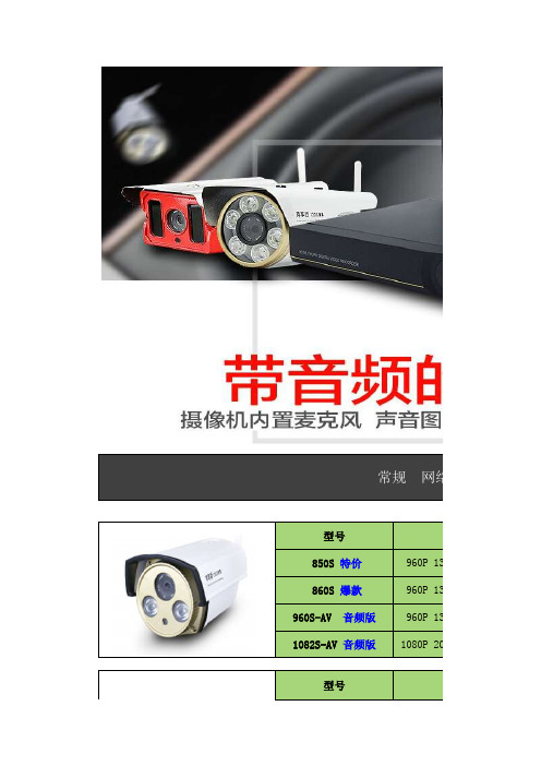
对每个常规 网络摄型号分850S 特价960P 130万860S 爆款960P 130万960S-AV 音频版 960P 130万华为海思1082S-AV 音频版1080P 200万型号分2501S (H.265)06SE 960P 9003(捷安锐视)1080P1300S 960P1185S 星光全彩1080P日夜全彩 白光摄像机1600S1080P 9200S 1080P型号分型号分6130S-AV 音频版960P 6200S-AV 音频版1080P 3MP型号分 1086S 推荐1080P 200万型号分5130S960P 861S960P 130万 862S 爆款960P 130万 1083S1080P 200万2506S (H.265)智能球形变倍一体机特殊场合 网络红激光 夜视王7621S 1080P 型号分型号分7613S960P 7620S1080P Q1960P 1305倍Q2 1080P 2 5倍Q3 1080P 2 25倍3MP型号分特点:室内室外防雨 4.5寸迷你球机 6颗阵列红外灯 5倍支持360度旋转 支持预置位 支持手机远程控制、手机录像。
可无线连4.5寸迷你球道路车牌摄像机防爆摄像机防爆摄像机电梯专用摄像机银行专用摄像机2081S 全彩低照度1080P 2061S 全彩低照度1080P 型号分2080S1080P 6203S 音频版3MP 型号分2060S960P 型号分 6201S 音频版1080P 6202S 音频版1080P 6003S960P 6013S 1080P6033S1080P L6001080P L7001085P型号分L500960P9615AH AHD同轴960P 9610AH AHD同轴9196AH AHD同轴960P960P9612AH AHD同轴960P2000HD 模拟005HK 模拟81000TVL 605HD 模拟1000TVL型号分型号分型号分型号分模拟摄像机 AHD同型号分9660AH AHD同轴960P 7118HD 模拟812路 NVR 型号Smart-916S 16路画面显示 支持1块硬模式1:接入16路108支持自组网一键添加 ,支持音频输出 可接音响耳机 即插即用,型号Smart-912S 12路画面显示,支持1块硬模式1:接入12路96模式2:接入9路108支持音频输出 可接音响耳机 即插即用,NVR网络录像型号Smart-904S 6路画面显示,支持1块硬支持 接入6路1080支持自组网一键添加 ,支持音频输出 可接音响耳机 即插即用,型号Smart-906S 6路画面显示,支持1块硬6路 NVR 4路 NVR 支持 接入6路108025路 NVR 4路 混合录像机16路 NVR 36路 NVR 4盘位即插即用,一键远程4合一 混合硬盘型号:6804S 4路画面显示,支持1块硬盘同时支持模拟摄像机、AH支持自组网一键添加 ,即插即用,一键支持自组网一键添加 ,支持音频输出 可接音响耳机 即插即用,型号Smart-936S 36路画面显示,支持4块硬模式1:接入36路96模式2:接入35路108型号:6808S 8路画面显示,支持1块硬盘同时支持模拟摄像机、AH即插即用型号Smart-925S 25路画面显示,支持2块硬模式1:接入25路108H.265 NVR录像机 4路 H.265 NVR 8路 混合录像机16路 混合录像机32路 混合录像机支持V390全景摄像机 多种模式显示 支持自型号:9804S 4路画面显示,支持1块硬盘存储减半 最高支持支持V390全景摄像机 多种模式显示 支持自即插即用,一键型号:9808S 8路画面显示,支持1块硬盘存储减半 最高支持支持自组网一键添加 ,即插即用,一键型号:6632S 32路画面显示,支持4块硬盘同时支持模拟摄像机、AH支持自组网一键添加 ,即插即用,一键即插即用,一键型号:6616S 16路画面显示,支持2块硬盘同时支持模拟摄像机、AHPOE 网络监一根网络线 同时传输电源与信号8路 H.265 NVR 32路 H.265 NVR 16路 H.265 NVR 一根网络线 同时传输电源无需交换机、无需电源线型960P 130万华为海思方案一根网络线 同时传输电源型号:9832S 32路画面显示,支持4块硬盘存储减半 最高支持支持V390全景摄像机 多种模式显示 支持自即插即用,一键型960P 130万华为海思方案即插即用,一键型号:9816S 8路画面显示,支持1块硬盘存储减半 最高支持支持V390全景摄像机 多种模式显示 支持自即插即用,一键全景 网络监一台顶多台 全方位无死角监控 同步录音录4路 POE NVR 8路 POE NVR 型号:3 300万像素支持语音对讲 远程监最大支持128G TF卡共计9个网口 8个网口支持2块硬盘,型号:1200万像素支持语音对讲 远程监最大支持128G TF卡内置拾音器,V6方型4路画面显示 接入最大4共计5个网口 4个网口无需交换机 支型8路画面显示接入 最大8无需交换机、无需电源线免布线 电力网络一根电力线 同时传输多个摄像机 最远60 农行卡号:622 849 06300 1210 9510 户名:孙恒 邮政新卡号: 622 188 12100 2364 9705 户名:孙恒资中行:6216 615 00000 2408 071 户名:孙恒资工商:6222 08040 20014 07068 户名:孙恒资 开户行:中华 建行:4367 4201 3039 8652 954 户名:孙恒资支付宝:136******** 孙国强 以上报价不含税票及运费 (公司可开增全景专用 8路NVR 全景专用 4路NVR 最高可接入4路5M支持HDMI输出 即插即用,一键远型号 9808 8路画面显示,支持1块硬盘支持2分割画面、4分最高可接入8路5M支持HDMI输出 即插即用,一键远内置拾音器,V6方型号 9804 4路画面显示,支持1块硬盘支持2分割画面、电力网络传可实现电力猫功省去交换机、电源线、网支持任何品牌网络电力需配合 电力网络传省去交换机、电源线、网支持任何品牌网络10台起 价格69元76元100元12610台起 价格网络摄像机V6方案 H.264压缩格式全铝合金结构 75口径2颗晶元点阵红外灯最远夜视距离50米以上性能130万像素 华为海思200万像素 华为海思分辨率分辨率性能 130万像素 国科芯片130万像素 V6AK芯片全铝合金结构 100口径机机195元机机130元220元VIP价格60元75元力猫功能 同电表内 多个使用线、网线、监控电源、防水盒一半人工费牌网络NVR录像机、网络IPC摄像机电力网络接收器网络传输器 (发射器 )。
泽安171169产品说明书

Eaton 171169Eaton Moeller series xEffect - FRCmM-125 Type A RCCB.Residual current circuit breaker (RCCB), 125A, 2p, 100mA, type G/AGeneral specificationsEaton Moeller series xEffect - FRCmM-125 Type A RCCB1711694015081676538FRCMM-125/2/01-G/A 85 mm 75.5 mm 36 mm 0.28 kg RoHS conformIEC/EN 61008 ÖVE E 8601Product NameCatalog Number EANModel CodeProduct Length/Depth Product Height Product Width Product Weight Compliances CertificationsTwo-poleShort time-delayed10 ms delayed125 A10 kA with back-up fuse 100 mAPulse-current sensitive3 kA (8/20 μs) surge-proof 240 V AC240 V440 V4 kV0.1 A0.1 A50 Hz125 A (max. admissible back-up fuse) A1250 A80 A gG/gL10 kA3 kA184 V AC - 250 V AC24000 operationsApplicationNumber of polesTripping timeAmperage RatingRated short-circuit strength Fault current rating Sensitivity typeImpulse withstand current Type Voltage rating (IEC/EN 60947-2)Rated operational voltage (Ue) - maxRated insulation voltage (Ui)Rated impulse withstand voltage (Uimp) Rated fault current - minRated fault current - maxFrequency ratingShort-circuit ratingLeakage current typeRated residual making and breaking capacity Admissible back-up fuse overload - max Rated short-time withstand current (Icw) Surge current capacityTest circuit rangePollution degreeLifespan, electricalSwitchgear for industrial and advanced commercial applicationsxEffect - Switchgear for industrial and advanced commercial applicationsFRCmM-125Residual current circuit breakersType G/A (ÖVE E 8601)45 mm235 mm (2 SU)70.5 mmDIN railQuick attachment for DIN-rail EN 50022As requiredIP20, IP40 with suitable enclosureIP20Toggle-center postitionTwin-purpose terminals1.5 mm² - 50 mm²1.5 mm² - 16 mm² (2x)1.5 mm²50 mm²1.5 mm² - 16 mm² (2x)1.5 mm² - 5 mm²1.5 mm²16 mm²Finger and hand touch safe, DGUV VS3, EN 50274 Red / green 125 A0 W18 W0 W0 W-25 °C60 °CMeets the product standard's requirements.Meets the product standard's requirements.Meets the product standard's requirements.Meets the product standard's requirements.Meets the product standard's requirements.Does not apply, since the entire switchgear needs to be evaluated.Does not apply, since the entire switchgear needs to be evaluated.Meets the product standard's requirements.Does not apply, since the entire switchgear needs to beFrameWidth in number of modular spacingsBuilt-in width (number of units)Built-in depthMounting MethodMounting positionDegree of protectionStatus indicationTerminals (top and bottom)Terminal capacity (solid wire)Connectable conductor cross section (solid-core) - min Connectable conductor cross section (solid-core) - max Terminal capacity (stranded cable)Connectable conductor cross section (multi-wired) - min Connectable conductor cross section (multi-wired) - max Terminal protectionContact position indicator color Rated operational current for specified heat dissipation (In) Heat dissipation per pole, current-dependentEquipment heat dissipation, current-dependentStatic heat dissipation, non-current-dependentHeat dissipation capacityAmbient operating temperature - minAmbient operating temperature - max10.2.2 Corrosion resistance10.2.3.1 Verification of thermal stability of enclosures10.2.3.2 Verification of resistance of insulating materials to normal heat10.2.3.3 Resist. of insul. mat. to abnormal heat/fire by internal elect. effects10.2.4 Resistance to ultra-violet (UV) radiation10.2.5 Lifting10.2.6 Mechanical impact10.2.7 Inscriptions10.3 Degree of protection of assemblies0.8 mm - 2 mm 10000 operations-25 °C60 °C25-55 °C / 90-95% relative humidity according to IEC 60068-2evaluated.Meets the product standard's requirements.Does not apply, since the entire switchgear needs to be evaluated.Does not apply, since the entire switchgear needs to be evaluated.Is the panel builder's responsibility.Is the panel builder's responsibility.Is the panel builder's responsibility.Is the panel builder's responsibility.Is the panel builder's responsibility.The panel builder is responsible for the temperature rise calculation. Eaton will provide heat dissipation data for the devices.Is the panel builder's responsibility. The specifications for the switchgear must be observed.Is the panel builder's responsibility. The specifications for the switchgear must be observed.The device meets the requirements, provided the information in the instruction leaflet (IL) is observed.Additional equipment possible Residual current circuit breaker eaton-rcd-application-guide-br019003en-en-us.pdf eaton-xeffect-frcmm-125-rccb-catalog-ca003020en-en-us.pdfBusbar material thickness Lifespan, mechanical Permitted storage and transport temperature - min Permitted storage and transport temperature - max Climatic proofing10.4 Clearances and creepage distances 10.5 Protection against electric shock10.6 Incorporation of switching devices and components 10.7 Internal electrical circuits and connections 10.8 Connections for external conductors 10.9.2 Power-frequency electric strength 10.9.3 Impulse withstand voltage 10.9.4 Testing of enclosures made of insulating material 10.10 Temperature rise10.11 Short-circuit rating10.12 Electromagnetic compatibility10.13 Mechanical functionFeaturesFitted with:Application notesCatalogsEaton Corporation plc Eaton House30 Pembroke Road Dublin 4, Ireland © 2023 Eaton. All Rights Reserved. Eaton is a registered trademark.All other trademarks areproperty of their respectiveowners./socialmediaInterlocking deviceShort-time delayed trippingResidual current circuit breakers FRCmM-125Type G/A (ÖVE E 8601)eaton-xeffect-industrial-switchgear-range-catalog-ca003002en-en-us.pdf DA-DC-03_FRCmMas_frcmmeaton-frcm-dimensions.jpgIL019140ZUdfs_2.dwgdfs_2.stpeaton-xeffect-frcmm-125-rccb-wiring-diagram-002.jpgFunctions Special featuresUsed with Certification reports DrawingsInstallation instructions mCAD modelWiring diagramsCurrent test marks as per inscriptionMaximum operating temperature is 60 °C: Starting at 40 °C, the max. permissible continuous current decreases by 2.2% for every 1 °C。
敦泰触摸IC参数对照表
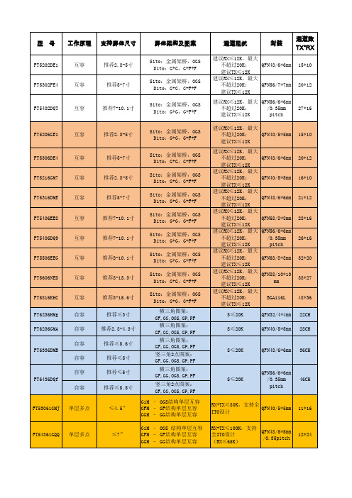
20*12
FT5402DQT
互容
推荐7-10.1寸
27*16
FT5206GE1
互容
推荐2.8-5寸
Sito:金属架桥,OGS Dito:G+G,G+F+F Sito:金属架桥,OGS Dito:G+G,G+F+F Sito:金属架桥,OGS Dito:G+G,G+F+F Sito:金属架桥,OGS Dito:G+G,G+F+F Sito:金属架桥,OGS Dito:G+G,G+F+F Sito:金属架桥,OGS Dito:G+G,G+F+F Sito:金属架桥,OGS Dito:G+G,G+F+F Sito:金属架桥,OGS Dito:G+G,G+F+F Sito:金属架桥,OGS Dito:G+G,G+F+F 横三角图案: GF,GG,OGS,GP,PF 横三角图案: GF,GG,OGS,GP,PF 横三角图案: GF,GG,OGS,GP,PF 竖三角2点图案: GF,GG,OGS,GP,PF 横三角图案: GF,GG,OGS,GP,PF 竖三角2点图案: GF,GG,OGS,GP,PF G1M – OGS结构单层互容 GFM – GF结构单层互容 GGM – GG结构单层互容 G1M – OGS 结构单层互容 GFM – GF结构单层互容 GGM – GG结构单层互容
工作电流:6mA 待机电流:4mA 睡眠电流:30uA
工作温度: -20~+85 储存温度: -55~+150 工作温度: -20~+85 储存温度: -55~+150
远翔科技-IC选型表
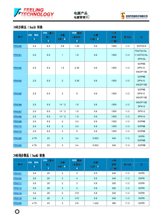
>>白光LED驱动器
型号
VIN(MIN) (V)
VIN(最大 值) (V)
VOUT (MAX)
(V)
#发光二 极管
(最大)
驱动 电流 (A)
LED 开路 普罗特。
FP7101A
4.75
23
16
4
2
FP7102
3.6
28
25
6
2
FP7103
3.6
28
25
6
3
FP7151
7
26
26
7
0.7
●
FP7152
3
25
FP103
2.5
32
FP115
3
20
IOUT (毫安)
20 20 20 100 10
参考 电压(V)
1.25 1.25 1.25 2.5 1.25
>>线性锂离子电池充电器
型号
VIN(MIN) (V)
VIN(最大 值) (V)
充电 电流(A)
涓流 充电
FP8102
4.25
5.5
1
是的
FP8103
●
FP5453
3.6
30
调整
调整
外部
●
FP5462
3.6
40
调整
调整
外部
●
●
SOP8
SOP16 ●
SSOP16
SOP16 ●
SSOP16
SOP16 ●
SSOP16
SOP16 ●
SSOP16
>>非同步升压(升压)转换器
型号
VIN(MIN) (V)
VIN(最大 值) (V)
黑金刚
高 信 形状
品
薄 型 化
波 化
命
赖 性
工作上限温度· 标准寿命 (hours)
额定电压范围 (Vdc)
105℃超小型化品 85℃小型化品 105℃小型化品 85℃小型化标准品 105℃小型化标准品 105℃小型化标准品 85℃标准品(160Vdc以上请参照No585公报) 105℃标准品(160Vdc以上请参照No585公报) 85℃高15mm薄型品 105℃高15mm薄型品 小型化长寿命品 105℃小型化长寿命品 小型化长寿命品 长寿命品 对应异常电压·小型化高纹波品 对应异常电压·小型化品 伺服·变频器用充放电对应品(详情请参照No781公报) 85℃标准品 105℃标准品 85℃变频器高纹波小型化品 变频器用高纹波品 变频器用高耐压小型化品 变频器用高耐压品 变频器用高纹波品 变频器用长寿命品 椭圆形状·变频器用高纹波品 105℃高耐压·变频器用长寿命品 105℃变频器用高纹波长寿命品 伺服·变频器用充放电对应品(详情请参照No782公报)
铝电解电容器
产品指南
接前页
标 准
小 型 ·
低
长 寿
高 信 形状
品
薄 型 化
Z化 命
赖 性
工作上限温度· 标准寿命 (hours)
额定电压范围 (Vdc)
04 105℃
3,000 6.3 ~ 50
04 125℃ 3,000/5,000 25 ~ 50
04 125℃ 2,000~5,000 10 ~ 450
04 125℃
5,000 10 ~ 50
04 105℃
5,000
25、35
04 105℃
2,000 6.3 ~ 16
04
MagnTek MT6816 高分辨率无延迟磁场角度位置传感器IC说明书

Features and Benefits■Based on advanced AMR Technology with 0~360°Full Range Angle Sensing ■14 bit Core Resolution■Maximum Rotation Speed 25,000 RPM ■Output Propagation Delay <2 us■-40~125℃ Industry Operating Temperature Range■Output Interface: ABZ、UVW,PWM or SPI ■Incremental ABZ Resolution 1~1024 Pulses per Revolution User Programmable ■UVW Output Resolution 1~16 Pole-Pairs per Revolution User Programmable ■SOP-8 PackageGeneral DescriptionTheMagnTekrotarypositionsensorMT6816is an IC based on advanced AMR technology.A rotating magnetic field in the x-y sensor plane delivers two sinusoidal output signals which indicating the angle(α)between the sensor and the magneticfield direction.The sensor is only sensitive to the magnetic field direction in x-y plane as the sensing element output is specially designed to be independent from the magnet field strength.This allows the device to be less sensitive to magnet variations,stray magnetic fields,air gap changes and off-axis misalignment.TheincrementalABZoutputmodeisavailable in this sensor series,making thechip suitable to replace various optical encoders.The maximum resolution is 4096steps or 1024pulses per revolutionA standard SPI (3-Wire or 4-Wire)interface allows a host microcontroller to read out the 14-bit absolute angle position data from MT6816.The absolute angle position is also provided as a 12bit PWM output.Applications■Absolute Angle Position Sensor ■BLDC Motor Control ■Servo Motor Control ■Stepping Motor Control ■Optical EncoderReplacementTable of ContentsFeatures and Benefits (1)Applications (1)General Description (1)1Pin Configuration (3)2Function Diagram (4)3Absolute Maximum Ratings (5)4Operating Conditions (5)5Electrical Characteristics (6)6Magnetic Input Specifications (8)7Output Mode (9)7.1I/O Pin Configuration (9)7.2Reference Circuit for ABZ,UVW and PWM Mode (10)7.3Quadrature A,B and Zero-Position Output Signal(ABZ Mode) (11)7.4UVW Output Mode (15)7.5Pulse Width Modulation(PWM)Output Mode (16)7.6SPI Interface (17)7.6.1SPI Reference Circuit (17)7.6.2SPI Timing Diagram (18)7.6.34-Wire SPI (19)7.6.43-Wire SPI (20)7.6.5SPI Read Angle Register (21)8MTP Programming (23)9Magnet Placement (24)10Mechanical Angle Direction (25)11Package Information (26)12Copy Rights and Disclaimer (27)13Revision History (28)1. Pin Configuration3Figure 1: Pin Configuration of MT6816(SOP-8) PackagePart Number DescriptionMT6816CTSOP-8 Package, Tube Pack (100pcs/Tube) or Tape & Reel Pack (3000pcs/Reel)Family MembersPin List*SOP-8 Reflow Sensitivity Classification: MSL-3Sensing Center at Geometry Center12348765Name #Type Description CSN 1Digital Input SPI Chip SelectionHVPP 2Power Supply OTP Programming Supply(7V)or SPI Enable OUT 3Digital Output PWM Output VDD 4Power Supply 3.3~5.0V SupplyA/U 5Digital Input/output Incremental Signal A/U or SPI MOSI(4-Wire), SDAT(3-Wire)B/V 6Digital Input/output Incremental Signal B/V or SPI MISO(4-Wire)Z/W 7Digital Input Incremental Signal Z/W or SPI Clock GND8GroundGround2. Functional DiagramFigure 2: Block DiagramThe MT6816is manufactured in a CMOS standard process and uses advanced magnet sensing technology to sense the magnetic field distribution across the surface of the chip.The integrated magnetic sensing element array is placed around the center of the device and delivers a voltage representation of the magnetic field at the surface of the IC.Figure 2shows a simplified block diagram of the chip,consisting of the magnetic sensing element modeled by two interleaved Wheatstone bridges to generate cosine and sine signals,gain stages,analog-to-digital converters (ADC)for signal conditioning,and a digital signal processing (DSP)unit for encoding.Other supporting blocks such as LDO,etc.are also included.G GADCADCDSPLDO CalibrationNVMABZ /-A-B-ZPWMVDD HVPPA B ZOUTCSNM U XOSCSPIUVWVSS Angle CalculationInterpolatorMagnetic Sensing ElementI/V REF3. Absolute Maximum Ratings (Non-Operating)ParameterMin.Max.Unit NotesDC Voltage at Pin VDD -0.5 6.5V DC Voltage at Pin HVPP-0.58V Terminal Voltage at Input and Output Pins -0.5VDD V ABZ,OUT Output Current at Output Pins -2020mA ABZ, OUT Storage Temperature-55150℃Electrostatic Discharge (CDM)-±1.0KV Electrostatic Discharge (HBM)-±3.0KVStresses beyond those listed under “Absolute Maximum Ratings”may cause permanent damage to the device.These are stress ratings only.Functional operation of the device at these or any other conditions beyond those indicated under “Operating Conditions”is not implied.Exposure to absolute maximum rating conditions for extended periods may affect device reliability.4. Operating ConditionsParameterMin.Max.Unit DC Voltage at Pin VDD3.0 5.5V DC Voltage at Pin HVPP (If Used) 6.757.25V Magnetic Flux Density Range 301,000mT Rotation Speed -25,000RPM Operating Temperature-40125℃5. Electrical CharacteristicsOperation conditions:Ta=-40to 125℃,VDD=3.0~5.5V unless otherwise noted.Symbol1Parameter Conditions/Notes Min.Typ.Max.Unit VDD Supply Voltage - 3.0 3.3~5.0 5.5V HVPP Supply Voltage - 6.757.07.25V Idd Supply Current -51015mA LSB Resolution (ABZ Mode)N Steps per Cycle -360°/N -°INL Integral Non-Linearity Note(1)-±0.75±1.5°DNL Differential Non-Linearity (ABZ Mode), Figure 3@1000 PPR-±0.01-°TN Transition Noise (ABZ Mode)25℃, HYST=4 Note(2)-0.01-°rms Hyst Hysteresis (ABZ Mode)HYST=0 Note(2)-0.022-°T PwrUp Power-Up Time VDD Ramp<10us-16-ms T DelayPropagation Delay-13usPWM Output Characteristics Conditions/Notes Min.Typ.Max.Unit FPWM PWM Frequency Programmable -971.1/485.6-Hz T Rise Rising Time C L =1nF --1us T FallFalling TimeC L =1nF--1usNote (1):The typical error value can be achieved at room temperature and with no off-axis misalignment error.The maximum error value can be achieved over operation temperature range,at maximum air gap and with worst-case off-axis misalignment error.Note (2):HYST could be set to:0=1LSB,1=2LSB,2=4LSB,3=8LSB,4=0LSB,5=0.25LSB,6=0.5LSB,7=1LSB.Here 1LSB=360°/214=0.022°.Digital I/O Characteristics(Push-Pull Type in Normal Mode)Symbol Parameter Conditions/Notes Min.Typ.Max.Unit V IH High Level Input Voltage-0.7*VDD--V V IL Low Level Input Voltage---0.3*VDD V V OH GPIO Output High Level Push-pull (Iout=2mA)VDD-0.25--V V OL GPIO Output Low Level Push-pull(Iout=2mA)--0.25VFigure 3: Drawing Illustration INL, DNL and TN (for 10 bit case)6. Magnetic Input SpecificationsOperation conditions:Ta=-40to 125℃,VDD=3.0~5.5V unless otherwise noted,two-pole cylindrical diametrically magnetized source.Symbol ParameterConditions/Notes Min.Typ.Max.UnitDmag Diameter of Magnet Recommended Magnet: Ø10mm x 2.5mm for Cylindrical Magnets -10-mmTmag Thickness of Magnet -- 2.5-mm Bpk Magnetic Input Field Amplitude Measure at the IC Surface 30-1,000mT AG Air Gap Magnetic to IC Surface Distance- 2.0 3.0mm RSRotation Speed--25,000RPMDISPOff Axis MisalignmentMisalignment ErrorBetween Sensor Sensing Center and Magnet Axis (See Figure 4)--0.3mmTCmag1Recommended Magnet Material and Temperature Drift CoefficientNdFeB (Neodymium Iron Boron)--0.12-%/℃TCmag2SmCo (Samarium Cobalt)--0.035-Figure 4: Magnet ArrangementAir GapOff-axis MisalignmentN S7. Output ModeThe MT6816provides ABZ,UVW and PWM signals at output pins,and also 14-bit absolute angle position data could be transferred by SPI interface (Both 3-Wire and 4-Wire modes).7.1 I/O Pin ConfigurationPin#3-Wire SPI4-Wire SPIABZ+PWMUVW+PWM1CSN CSN VDD VDD 3PWM PWM PWM PWM 5SDAT MOSI A U 6-MISO B V 7SCKSCKZWI/O Pin Configuration For SOP-8package,ABZ,UVW,PWM and SPI Interface are configured as below table.Figure 5: ABZ, UVW and PWM Output Reference Circuit w/o MTP Programming7.2 Reference Circuit for ABZ, UVW and PWM ModeFigure 6: ABZ, UVW and PWM Output Reference Circuit w/i MTP Programming12348765A/UB/V Z/W VDDTVS(6V)0.1ufPWM NC12348765A/UB/V Z/W VDDTVS(6V)0.1ufPWM HVPP1uf NC7.3 Quadrature A,B and Zero-Position Output (ABZ Mode)As shown in Figure 7,when the magnet rotates counter-clock-wise (CCW),output B leads output A by 1/4cycle,when the magnet rotates clock-wise (CW),output A leads output B by 1/4cycle (or 1LSB).Output Z indicates the zero position of the magnet.After chip power-on,the ABZ output is blocked for 16ms to guarantee proper output.Figure 7: ABZ output with VDD power onAZCCWB360°VDDCW16msOutput Z indicates the zero position of the magnet and the pulse width of Z is selectable as 1,2,4,8,12,16LSBs and 180°as shown in Figure 8and Figure 9.It is guaranteed that one Z pulse is generated for every rotation.The zero position is user programmable。
恩尼特克 型号对照表
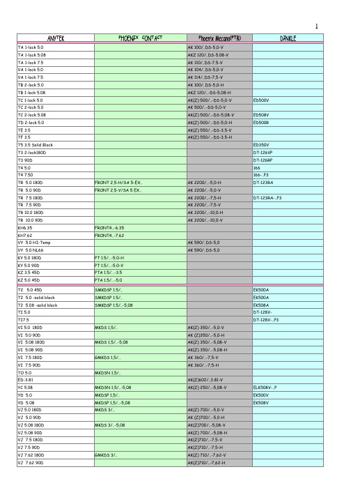
TA 1-lock 5.0AK 100/..DS-5,0-VTA 1-lock 5.08AKZ 120/..DS-5.08-V TA 1-lock 7.5AK 110/..DS-7.5-VVA 1-lock 5.0AK 104/..DS-5,0-VVA 1-lock 7.5AK 114/..DS-7,5-VTB 2-lock 5.0AK 100/..DS-5,0-HTB 1-lock 5.08AKZ 120/..-DS-5,08-H TC 1-lock 5.0AK(Z) 500/..-DS-5,0-V TC 2-lock 5.0AK 500/..-DS-5,0-V TC 2-lock 5.08AK(Z) 500/..-DS-5,08-VTD 2-lock 5.0AK(Z) 500/..-DS-5,0-H TE 3.5AK(Z) 550/..-DS-3.5-V TF 3.5AK(Z) 550/..-DS-3.5-H T5 3.5 Solid BlockT3 2-lock180DT3 90DT4 5.0T4 7.50TR 5.0 180D FRONT 2,5-H/SA 5-EX..AK 2200/..-5,0-HTR 5.0 90D FRONT 2,5-V/SA 5 EX..AK 2200/..-5,0-VTR 7.5 180D AK 2200/..-7,5-HTR 7.5 90D AK 2200/..-7,5-VTR 10.0 180D AK 2200/..-10,0-H TR 10.0 90D AK 2200/..-10,0-VKH6.35FRONT4..-6.35KH7.62FRONT4..-7.62VY 5.0 HI-Temp AK 590/..DS-5,0VY 5.0 NL66 AK 590/..DS-5,0KY 5.0 180D PT 1.5/…-5.0-HKY 5.0 90D PT 1.5/…-5.0-VKZ 3.5 45D PTA 1.5/…-3.5KZ 5.0 45D PTA 1.5/…-5.0T2 5.0 45D SMKDSP 1.5/..T2 5.0 -solid block SMKDSP 1.5/..T2 5.08 -solid block SMKDSP 1.5/..-5,08TI 5.0TI7.5VI 5.0 180D MKDS 1,5/..AK(Z) 350/..-5,0-VVI 5.0 90D AK (Z)350/..-5,0-HVI 5.08 180D MKDS 1,5/..-5,08AK(Z) 350/..-5,08-V VI 5.08 90D AK(Z) 350/..-5,08-H VI 7.5 180D GMKDS 1,5/..AK 360/..-7,5-VVI 7.5 90D AK 360/..-7,5-HTO 5.0MKDSN 1,5/..ED-3.81AK(Z)602/..3.81-V YC 5.08MKDSN 1,5/..-5,08AK(Z) 250/..-5,08-V YD 5.0MKDSP 1,5/..YD 5.08MKDSP 1,5/..-5,08VJ 5.0 180D MKDS 3/..AK(Z) 700/..-5,0-V VJ 5.0 90D AK (Z)700/..-5,0-H VJ 5.08 180D MKDS 3/..-5,08AK(Z)700/..-5,08-V VJ 5.08 90D AK(Z) 700/..-5,08-H VJ 7.5 180D AK(Z)710/..-7,5-VVJ 7.5 90D AK(Z)710/..-7,5-HVJ 7.62 180D GMKDS 3/..AK(Z) 710/..-7,62-V VJ 7.62 90D AK(Z)710/..-7,62-H ED500RDT-123RA-..P3DT-128V-DT-128V-..P3 ED500VDT-123RA 166-..P3166DT-126VP ED350VED508VELK508V-..P EK508VDT-126RPEK508AEK500AEK500AEK500VYE 5.0YE 5.08YL- L(YD+YE) 5.0YL- R(YD+YE) 5.0MKKDS 1,5/..AK 370/..-5,0-VYL- L(YD+YE) 5.08YL- R(YD+YE) 5.08MKKDS 1,5/..-5,08YB-5.08(Solid block) MK3DSN1.5YO 3.5MKDS 1/..-3,5YO 3.81MKDS 1/..-3,81YP 3.5YP 3.81YQ- L(YO+YP) 3.5MKKDS 1/..-3,5YQ -R(YO+YP) 3.5MKKDS 1/..-3,5YQ- L(YO+YP) 3.81MKKDS 1/..-3,81YQ- R(YO+YP) 3.81MKKDS 1/..-3,81YA Triple (S-block) 3.81MK3DS 1YA3.81(Stackable)MK3DS1YF 5.0YF 5.08YM- L(YE+YF) 5.0YM- R(YE+YF) 5.0YM- L(YE+YF) 5.08YM- R(YE+YF) 5.08YN Triple 5.0YN Triple 5.08YH 5.0/5.08 MK3DS 3/..5.08AKZ770/..-5,08-V EHK508V3L YT 5.0/5.08MK4DS1.5YI 5.0/5.08VV 6.35MKKDS 5/..-6,35VV 9.52MKKDS 5/..-9,5YS 5.0MKKDSN 1.5/YS 5.08MKKDSN 1.5/..-5,08VQ 3.5 DIP SOLDER AKZ 602/..-3,5-VVQ 3.81 DIP SOLDER AKZ 602/..-3,81-VTV 3.5 45D SMKDS 1/..-3,5TV 3.81 45D SMKDS 1/..-3,81KP 6.35MKDS 5HV/..-ZB-6.35KP 10.16(Double interlace )MKDS 10HV/..-ZB-10.16KP 10.16(Front single row)MKDS 10HV/..-B-10.16KP 10.16( Back single row)MKDS 10HV/..-F-10.16T7 6.35MKDS 5/..-6,35T7 6.35 45D SMKDS 5/..-6.35T7 7.62MKDS 5/..-7,62KO 9.52(Back single row)MKDS 5HV/..-9.52KO 9.52(Interlace tail)MKDS 5HV/..-9.52-ZT7 9.52 180D MKDS 5/..-9,5T7 9.52 45D SMKDS 5/..-9,5KQ 10.16MKDSP10HV..-10.16VP 10.16(Single tail)MKDSP10HV..-10.16VP 12.7MKDSP10HV..-12.7EI 15.00MKDSP 25/..-15EI 15.00 W/F MKDSP 25/..-15-FEK 5.08MKDS 3/..-5,08VN 2.54MPT 0,5/..-2,54 VT 5.08KDS 3-MTV4 Solid Block G 10/...E4 Solid Block G 5/...EK254V EHK508V ESK950V ESK116V EELK508V-..P EK381AEK350A ESK762V ESK635V EK508V3L EK500V3L EK508V2L EK508V2R EK500V2L EK500V2R EEK350VE3K500V EK371V3L EK381V4L EK381V4R EK350V4L EK350V4R EK350VEK508V4L EK508V4R EK500V4L EK500V4R EEK508V EK381V EEK500VE3K508V EEK381V ESK116VES 5.0MKDSFW1.5EB 5.0 Interlace MKKDS3/..AK(Z)750/..-5.0-V EB 5.08 Interlace MKKDS3/..-5.08AK(Z)750/..-5.08-V EEHK508VEB 5.0 Parallel MKKDSG 3/..AK790/..-5.0-V EB 5.08 Parallel MKKDSG 3/..-5.08AK790/..-5.08-VES 5.0MKDSFW1,5/..TI 7.62GMKDS1,5/..-7,62TG 5.0 45D AK (Z)300/..-5,0TG 5.08 45D AK(Z) 300/..-5,08TV 5.0 45D SMKDSN 1.5/..E6 5.0 RIGHT MKDSO 2.5/…-L E6 5.0 LEFT MKDSO 2.5/…-RTH 5.0AK 130/..-5,0TH 5.0Solid Block AK(Z) 130/..-5,0EH 3.5AK 1300/..-3,5OP/(EH) 3.5STL 1300/..-3,5-V OP 12.5 5.0STL 130/..-5,0-V OP 5.0 Bend pin STL 1340/..-5,0-H TJ 3.5MC 1,5/..-ST-3,5AK 1550/..-3,5TJ 3.5 W/F MC 1,5/..-STF-3,5AK 1550/..F-3,5TJ 3.81MC 1,5/..-ST-3,81AKZ 1550/..-3,81TJ 3.81 W/F MC 1,5/..-STF-3,81AKZ 1550/..F-3,81TJ 5.0MSTB 2,5/..-ST AK 950/..-5,0TJ 5.0 W/F MSTB 2,5/..-ST AK 950/..-F-5,0TJ 5.08MSTB 2,5/..-ST-5,08AKZ 950/..-5,08TJ 5.08 W/F MSTB 2,5/..-STF-5,08AKZ 950/..-F-5,08TJ 7.5GMSTB 2,5/..-ST TJ 7.5 W/F GMSTB 2,5/..-STF TJ 7.62GMSTB 2,5/..-ST-7,62AKZ 960/..-7,62TJ 7.62 W/FGMSTB 2,5/..-STF-7,62AKZ 960/..-F-7,62VR 5.08(contact down side)MC 1,5/..-STI-5.08VR 5.08 W/F(contact down side)MC 1,5/..-STIF-5.08VR 5.08(contact up side)MC 1,5/..-ST-5.08VR 5.08 W/F(contact up side)MC1,5/..-STF-5.08VS 5.08 180D MCV 1,5/..-G-5.08VS 5.08 W/F 180D MCV 1,5/..-GF-5.08VS 5.08 90D MC 1,5/..-G-5.08VS 5.08 W/F 90D MC 1,5/..-GF-5.08VH 5.08TMSTBP 2,5/..-ST-5,08VH 5.08 W/F TMSTBP 2,5/..-STF-5,08OQ 2.5 180D MCV 0,5/..-G-2.5OQ 2.5 90D MC 0,5/..-G-2.5OQ 3.5 180D MCV 1,5/..-G-3.5STL 1550/..G-3,5-V OQ 3.5 180D (W/F) MCV 1,5/..-GF-3.5STL 1550/..F-3,5-V OQ 3.5 90D MC 1,5/..-G-3.5STL 1550/..G-3,5-H OQ 3.5 90D (W/F) MC 1,5/..-GF-3.5STL 1550/..F-3,5-H OQ 3.81 180D MCV 1,5/..-G-3.81STLZ 1550/..G-3,81-V OQ 3.81 180D (W/F) MCV 1,5/..-GF-3.81STLZ 1550/..F-3,81-V OQ 3.81 90D MC 1,5/..-G-3.81STLZ 1550/..G-3,81-H OQ 3.81 90D (W/F) MC 1,5/..-GF-3.81STLZ 1550/..F-3,81-H OQ 5.0 180D (Open) MSTBV 2,5/..-G STL 950/..-5,0-V OQ 5.0 180D (Close) MSTBVA 2,5/..-G STL 950/..-G-5,0-V OQ 5.0 180D (W/F) MSTBV 2,5/..-GF STL 950/..-F-5,0-V OQ 5.0 90D (Open)MSTB 2,5/..-G STL 950/..-5,0-H OQ 5.0 90D (Close)MSTBA 2,5/..-G STL 950/..-G-5,0-H OQ 5.0 90D (W/F)MSTB 2,5/..-GFSTL 950/..-F-5,0-H5EHDRM5EHDRC 5EHDR 5EHDVM 5EHDVC 5ESDV 3ESDVM 3ESDV 7ESDVM 7ESDV 2ESDVM 2ESDV 5ESDVM ECH350RM ECH350R ECH350VM 5EHDV ECH381RM ECH381R ECH381VM ECH381V EC381VM EC381V EC350VM EC350V EDH130ED130ECH350V ECH250R ECH250VOQ 5.08 180D (Open) MSTBV 2,5/..-G-5,08STLZ 950/..-5,08-V OQ 5.08 180D (Close) MSTBVA 2,5/..-G-5,08STLZ 950/..-G-5,08-V OQ 5.08 180D (W/F) MSTBV 2,5/..-GF-5,08STLZ 950/..-F-5,08-V OQ 5.08 90D (Open MSTB 2,5/..-G-5,08STLZ 950/..-5,08-H OQ 5.08 90D (Close) MSTBA 2,5/..-G-5,08STLZ 950/..-G-5,08-H OQ 5.08 90D (W/F) MSTB 2,5/..-GF-5,08STLZ 950/..-F-5,08-HOQ 7.5 180D (Open) GMSTBV 2,5/..-G OQ 7.5 180D (Close)GMSTBVA 2,5/..-G OQ 7.5 180D (W/F) GMSTBV 2,5/..-GF OQ 7.5 90D (Open)GMSTB 2,5/..-G OQ 7.5 90D (Close) GMSTBA 2,5/..-G OQ 7.5 90D (W/F) GMSTB 2,5/..-GF OQ 7.62 180D (Open) GMSTBV 2,5/..-G-7,62STLZ 960/..-7.62-V OQ 7.62 180D (Close) GMSTBVA 2,5/..-G-7,62STLZ 960/..-G-7.62-VOQ 7.62 180D (W/F) GMSTBV 2,5/..-GF-7,62OQ 7.62 90D (Open) GMSTB 2,5/..-G-7,62STLZ 960/..-7.62-H OQ 7.62 90D (Close) GMSTBA 2,5/..-G-7,62STLZ 960/..-G-7.62-H OQ 7.62 90D (W/F) GMSTB 2,5/..-GF-7,62VK 3.5 45D SMC 1,5/..-G-3,5VK 3.5 45D (W/F) SMC 1,5/..-GF-3,5VK 3.81 45D SMC 1,5/..-G-3,81STLZ 1590/..G-3,81VK 3.81 45D (W/F) SMC 1,5/..-GF-3,81STLZ 1590/..F-3,81VK 5.0 45D (Open) SMSTB 2,5/..-G VK 5.0 45D (Close) SMSTBA 2,5/..-G VK 5.0 45D (W/F) SMSTB 2,5/..-GF VK 5.08 45D (Close)SMSTB 2,5/..-G-5,08STLZ 990/..G-5,08VK 5.08 45D (W/F) SMSTBA 2,5/..-G-5,08VK 5.08 45D (Open)SMSTB 2,5/..-GF-5,08VB 7.62PC 4/..-ST-7,62VB 7.62 (W/F)PC 4/..-STF-7,62VC 7.62 90D PC 4/..-G-7,62VC 7.62 90D(W/F)ECH762RM VC 7.62 180D PCV 4/..-G-7,62VC 7.62 180D(W/F)ECH762VM ET-7.62PC 5/..-ST-7,62ET-7.62 (W/F)PC 5/..-STF-7,62ET 7.62 flange with screw(with handle)PC 5/..-STF-SH-7.62EV-10.16PC 16/..-ST-10.16EC116VEV-10.16(W/F)PC 16/..-STF-10.16EV 10.16 flange with screw(with handle)PC16/..-STF-SH-10.16EW-10.16 180D PCV6-16/..-G1-10.16EW-10.16(W/F) 180D PCV6-16/..-G1F-10.16EW-10.16 90D(down)PC6-16/..-G1-10.16ECH116R EW-10.16 90D(up)PC6-16/..-G1U-10.16ECH116LEW-10.16 (W/F)90D(down)PC6-16/..-G1F-10.16EW-10.16(W/F) 90D(up)PC6-16/..-G1FU-10.16TJ 5.0 Contact on up side MSTBT2.5/..-ST TJ 5.0 Contact on up side(W/F)MSTBT2.5/..-STF TJ 5.08 Contact on up side MSTBT2.5/..-ST-5.08TJ 5.08 Contact on up side(W/F)MSTBT2.5/..-STF-5.08V9 5.08 W/O Flange fixed typeMSTBU2.5/..-STD-5.08V9 5.08 dinrail holder B type w/o flangeUMSTBVK2.5/..-ST-5.08V9 5.08 dinrail holder B type with flang UMSTBVK2.5/..-STF-5.08TJ 3.5/3.81 with handle AK(Z)1550TJ 5.0 with handle MSTB2.5/..-STZ AK(Z)950TJ5.08 with handle MSTB2,5/..-STZ-5.08AK(Z)950VB 7.62 with flangePC4/..-STF-7.62EC762V EC762VM ECH762R ECH762V 3EHDRM3EHDRC 3EHDVC 3EHDV 7EHDRM 3EHDR 3EHDVM 7EHDRC 7EHDR 7EHDVM 7EHDVC 7EHDV 2EHDRM 2EHDRC 2EHDR 2EHDVM 2EHDVC 2EHDV 5ESDTVC 7.62 with flange DFK-PC4/..-G-7.62-FS4,8VC 7.62 flange with Nut PC4/..-G-7,62TS A 3.5MCVR 1,5/..-ST-3,5TS A 3.5 (W/F) MCVR 1,5/..-STF-3,5TS B 3.5MCVW 1,5/..-ST-3,5TS B 3.5 (W/F)MCVW 1,5/..-STF-3,5TS A 3.81MCVR 1,5/..-ST-3,81AKZ 1700/..-3,81 TS A 3.81 (W/F)MCVR 1,5/..-STF-3,81AKZ 1700/..F-3,81 TS B 3.81MCVW 1,5/..-ST-3,81AKZ 1710/..-3,81 TS B 3.81 (W/F) MCVW 1,5/..-STF-3,81AKZ 1710/..F-3,81 TS A 5.0MVSTBR 2,5/..-ST AK 1100/..-5,0 TS A 5.0 (W/F) MVSTBR 2,5/..-STFTS B 5.0MVSTBW 2,5/..-ST AK 1110/..-5,0TS B 5.0 (W/F) MVSTBW 2,5/..-STFTS A 5.08MVSTBR 2,5/..-ST-5,08AKZ 1100/..-5,08 TS A 5.08 (W/F)MVSTBR 2,5/..-STF-5,08TS B 5.08MVSTBW 2,5/..-ST-5,08AKZ 1110/..-5,08 TS B 5.08 (W/F)MVSTBW 2,5/..-STF-5,08TS A 7.5GMVSTBR 2,5/..-STTS A 7.5 (W/F) GMVSTBR 2,5/..-STFTS B 7.5GMVSTBW 2,5/..-STTS B 7.5 (W/F) GMVSTBW 2,5/..-STFTS A 7.62GMVSTBR 2,5/..-ST-7,62TS A 7.62 (W/F)GMVSTBR 2,5/..-STF-7,62TS B 7.62GMVSTBW 2,5/..-ST-7,62TS B 7.62 (W/F) GMVSTBW 2,5/..-STF-7,62VM 3.81FRONT-MC 1,5/..-ST-3,81VM 3.81 W/F FRONT-MC 1,5/..-STF-3,81VM 5.0FRONT-MSTB 2,5/..-STVM 5.0 W/F FRONT-MSTB 2,5/..-STFVM 5.08AKZ 1200/..-5,08 VM 5.08 W/F FRONT-MSTB 2,5/..-STF-5,08AKZ 1200/..F-5,08 VM 5.08-low FRONT-MSTB 2,5/..-ST-5,08VM 7.62 FRONT-GMSTB 2,5/..-STVM 7.62 W/F FRONT-GMSTB 2,5/..-STFEM 5.0SMSTB 2,5/..-STEM 5.0 W/F SMSTB 2,5/..-STFEM 5.08SMSTB 2,5/..-ST-5,08EM 5.08 W/F SMSTB 2,5/..-STF-5,08EM 7.5GSMSTB 2,5/..-STEM 7.5 W/F GSMSTB 2,5/..-STFEM 7.62GSMSTB 2,5/..-ST-7,62EM 7.62 W/F GSMSTB 2,5/..-STF-7,62VL 2.5 180D MCDV 0,5/..-G1-2,5VL 2.5 90D MCD 0,5/..-G1-2,5VL 3.5 180D (B type)VL 3.5 180D W/F(B type)VL 3.5 90D (B type)VL 3.5 90D W/F(B type)VL 3.81 180D MCDV 1,5/..G1-3.81VL 3.81 180D W/F MCDV 1,5/..G1F-3.81VL 3.81 90D MCD 1,5/..G1-3.81VL 3.81 90D W/F MCD 1,5/..G1F-3.81VL 5.0 180D MDSTBV 2,5/..-G1STL 975/..G-5,0-V VL 5.0 180D (W/F)MDSTBV 2,5/..-G1FVL 5.0 90D MDSTB 2,5/..-G1STL 975/..G-5,0-H VL 5.0 90D(W/F) MDSTB 2,5/..-G1F ECHB381R ECHB350V ECHB381VM ECHB381V 2ESDFM ECHB350VM ECHB350RM ECHB381RM 5EHDBR5EHDBV5EHDBVM 2ESDAM2ESDAEC381REC350RLM EC350RL EC350RM EC350R5ESDP2ESDPLMECHB350R 5EHDBRM 2ESDPLM 2ESDPL7ESDPL7ESDPM EC381RM2ESDP3ESDPEC381RLM 5ESDPLM 5ESDPL5ESDPM7ESDPLM EC381RL7ESDP2ESDF5ESDFM5ESDF3ESDPLM 3ESDPL3ESDPMVL 5.08 180D MDSTBV 2,5/..-G1-5,08VL 5.08 180D(W/F)MDSTBV 2,5/..-G1F-5,08VL 5.08 90D MDSTB 2,5/..-G1-5,08VL 5.08 90D(W/F) MDSTB 2,5/..-G1F-5,08VO 3.5 180D MCDV 1,5/..-G-3,5VO 3.5 90D MCD 1,5/..-G-3,5VO 3.5 180D (W/F) MCDV 1,5/..-GF-3,5VO 3.5 90D (W/F) MCD 1,5/..-GF-3,5VO 3.81 180D MCDV 1,5/..-G-3,81STLZ 1570/..G-3,81-V VO 3.81 180D (W/F) MCD 1,5/..-G-3,81VO 3.81 90D MCDV 1,5/..-GF-3,81STLZ 1570/..G-3,81-H VO 3.81 90D (W/F) MCD 1,5/..-GF-3,81VF 5.0 180D Open MDSTBV 2,5/..-GVF 5.0 180D Close MDSTBVA 2,5/..-GVF 5.0 180D W/F MDSTBV 2,5/..-GFVF 5 .0 90D Open MDSTB 2,5/..-GVF 5.0 90D Close MDSTBA 2,5/..-GVF 5.0 90D W/F MDSTB 2,5/..-GFVF 5.08 180D Open MDSTBV 2,5/..-G-5,08STLZ 970/..-5,08-V VF 5.08 180D Close MDSTBVA 2,5/..-G-5,08VF 5.08 180D W/F MDSTBV 2,5/..-GF-5,08STLZ 970/..-F-5,08-V VF 5.08 90D Open MDSTB 2,5/..-G-5,08STLZ 970/..-5,08-H VF 5.08 90D Close MDSTBA 2,5/..-G-5,08VF 5.08 90D W/F MDSTB 2,5/..-GF-5,08STLZ 970/..-F-5,08-H VZ 3.81DFK-MC 1,5/..-GF-3,81VZ 5.08DFK-MSTB 2,5/..-GFV7 3.5 180D IMCV 1,5/..-GV7 3.5 180D (W/F) IMCV 1,5/..-GFV7 3.5 90D IMC 1,5/..-GV7 3.5 90D (W/F) IMC 1,5/..-GFV7 3.81 180D IMCV 1,5/..-G-3,81V7 3.81 180D (W/F)IMCV 1,5/..-GF-3,81V7 3.81 90D IMC 1,5/..-G-3,81V7 3.81 90D (W/F) IMC 1,5/..-GF-3,81V7 5.0 180D ICV 2,5/..-GV7 5.0 180D (W/F) ICV 2,5/..-GFV7 5.0 90D IC 2,5/..-GV7 5.0 90D (W/F) IC 2,5/..-GFV7 5.08 180D ICV 2,5/..-G-5,08V7 5.08 180D (W/F) ICV 2,5/..-GF-5,08V7 5.08 90D IC 2,5/..-G-5,08V7 5.08 90D (W/F) IC 2,5/..-GF-5,08V7 7.5 180D GICV 2,5/..-GV7 7.5 180D (W/F) GICV 2,5/..-GFV7 7.5 90D GIC 2,5/..-GV7 7.5 90D (W/F)GIC 2,5/..-GFV7 7.62 180D GICV 2,5/..-G-7,62V7 7.62 180D (W/F) GICV 2,5/..-GF-7,62V7 7.62 90D GIC 2,5/..-G-7,62V7 7.62 90D (W/F) GIC 2,5/..-GF-7,62EU-5.0-3P Right MSTBO2.5/3-6ST SET KMGY(Left)EU-5.0-3P Left MSTBO2.5/3-6ST SET KMGY(Right)EU-5.0-4P Right MSTBO2.5/4-6ST SET KMGY(Left)EU-5.0-4P Left MSTBO2.5/4-6ST SET KMGY(Right)V5 5.08 Bottom cover fixed type MVSTBU2.5/..-GB AKZS950/..GMB-5.08 V5 5.08 (W/F)Bottom cover fixed type MVSTBU2.5/..-GFBV5 5.08 Dinrail holder A type MSTBVK2,5/..-G-5.082ESDCV2ESDCRMZEHDRSMZEHDRS 2EEHDV2ESDCVMEECH381RM2EEHDR5EEHDRM5EEHDVECHP381VEECH350VMEECH350RMEECH381VEECH350REECH350V2EHDBRMEECH381VM2EHDBR5EEHDR2EEHDRM2EHDPEECH381R2EHDBVM2EHDBV5EEHDVM2EEHDVM2ESDCRV5 5.08 (W/F)Dinrail holder A type MSTBVK2,5/..-GF-5.08V5 5.08 Dinrail holder B type UMSTBVK2,5/..-G-5,08AKZS950/..G-5.08 V5 5.08 (W/F)Dinrail holder Btype UMSTBVK2,5/..-GF-5,08AKZS950/..F-5.08 KE 3.5 Close Vertical MCDNV1,5..-G1-3,5 P26THRKE 3.5 Close Right Angle MCDN1,5..-G1-3,5 P26THRKE 3.5 with holder Vertical MCDNV1,5..-G1-3,5 RNP26THRKE 3.5 with holder Right Angle MCDN1,5..-G1-3,5 RNP26THRKE 5.0 W/O FLANGE CCDN 2.5/…-G1 P26KE 5.0 W/FLANGE CCDN 2.5/…-G1F P26KK 10.16IPC 16..-ST-10,16KK 10.16 flange wih screw IPC 16..-STF-10,16KK 10.16 flange with screw (with handle IPC 16/..-STF-SH-10.16KK 10.16 flange with nut IPC 16/..-STGF-10.16KK 10.16 flange with nut (with handle)IPC 16/..-STGF-SH-10.16KL 10.16mm close Vertical IPCV 16/..-G-10,16KL 10.16 W/F close Vertical IPCV 16/..-GF-10,16KL 10.16 close Right angle(up)IPC 16/..-G-10,16KL 10.16 W/F close Right angle (up)IPC 16/..-GF-10,16KL 10.16 close Right angle(down)IPC 16/..-GU-10,16KL 10.16 W/F close Right angle (down)IPC 16/..-GUF-10,16KJ10.16PCU 6/..-STD-10,16V5 3.81(W/F)Bottom cover fixed type MCVU1,5/-GFD-3,81V8 3.81 w/o flange IMC1,5/..-ST-3,81V8 3.81 flange with Nut IMC1,5/..-STGF-3,81V8 5.08 w/o flange IC2,5/..-ST-5,08V8 5.08 flange with Nut IC2,5/..-STGF-5,08V8 5.08 flange with Screw IC2,5/..-STF-5,08V8 7.62 w/o flange GIC2,5/..-ST-7,62V8 7.62flange with Nut GIC2,5/..-STGF-7,62V8 7.62 flange with Screw GIC2,5/..-STF-7,62KF-3.5ZEC1,0/..-LPV-3,5KF-5.0ZEC1,0/..-LPV-5.0KF-7.5ZEC1,0/..-LPV-7,5KI3.81 W/O Flange MCC 1/..-STZ-3.81KI3.81 W/Flange MCC 1/..-STZF-3.81KI5.08 W/O Flange MSTBC 2.5/..ST-5.08KI5.08 W/Flange MSTBC 2.5/..STZF-5.08KV 5.08 W/Hook latch ICC 2.5/…-STZ-5.08KV 5.08 W/Flange Screw ICC 2.5/…-STZF-5.08KT 7.62 W/o flange IPC 5/…-ST-7.62KT 7.62 W/flange screw IPC 5/…-STF-7.62KT 7.62 W/flange and handle IPC 5/…-STF-SH-7.62KT 7.62 W/flange nut IPC 5/…-STGF-7.62KS 7.62 180D W/o flange IPCV 5/…-G-7.62KS 7.62 180D W/flange IPCV 5/…-GF-7.62KS 7.62 90D W/o flange PCB up IPC 5/…-G-7.62KS 7.62 90D W/o flange PCB down IPC 5/…-GU-7.62KS 7.62 90D W/flange PCB up IPC 5/…-GF-7.62KS 7.62 90D W/flange PCB down IPC 5/…-GFU-7.62VC 7.62 180D W/o flange B type PCV 5/…-G-7.62VC 7.62 180D W/flange B type PCV 5/…-GF-7.62VC 7.62 90D W/o flange PCB up PC 5/…-G-7.62VC 7.62 90D W/o flange PCB down PC 5/…-GU-7.62VC 7.62 90D W/flange PCB up PC 5/…-GF-7.62VC 7.62 90D W/flange PCB down PC 5/…-GUF-7.62KU 15.0 180D PCV 35 HC/…-GF-15.00KU 15.0 90D PC 35 HC/…-GF-15.00KU 15.0 90D With shield PC 35 HC/…-GF-SH-15.00KX 15.0 W/F PC 35 HC/…-STF-15.00KX 15.0 W/Handle(shield)PC 35 HC/…-STF-SH-15.00EU 3.5 Right MCO 1.5/…-G1R-3.5 KMGYEU 3.5 Left MCO 1.5/…-G1L-3.5 KMGYHI 5.0 -hook&Pillar AK 3950/..-5,0WAGO 2310134-12 HI 5.0 -W/Flange WAGO 231HI 5.0 -W/locking WAGO 2310134-14 HI 5.0 -100% protected against mismating WAGO 721HI 7.5 -hook&Pillar WAGO 2310134-32 HI 7.5 -W/Flange WAGO 231HI 7.5 -W/locking WAGO 2310134-34 HI 7.5 -100% protected against mismating WAGO 721HP 3.81QC 0,5/..-ST-3,81HP 3.81 W/F QC 0,5/..-STF-3,81HP 5.08QC 1/..-ST-5,08HP 5.08 W/F QC 1/..-STF-5,08HW 2.5FK-MC 0,5/..-ST-2,5ESC250V HW 3.5 w/o flange FK-MCP1,5/..-ST-3.5HW3.5 with flange FK-MCP1,5/..-STF-3.5HW 3.81FK-MCP 1,5/..-ST-3,81HW-3.81 W/F FK-MCP 1,5/..-STF-3,81ESC381VM HW 5.08 Contact on down side FKC 2,5/..-ST-5,08HW-5.08 W/F Contact on down side FKC 2,5/..-STF-5,08HW 5.08Contact on up side FKCT 2,5/..-ST-5,082ESDS HW-5.08 W/FContact on up side FKCT 2,5/..-STF-5,08HW 5.0 Contact on down side FKC 2,5/..-ST-5,0HW-5.0 W/F Contact on down side FKC 2,5/..-STF-5,0HW 5.0Contact on up side FKCT 2,5/..-ST-5,0HW-5.0 W/FContact on ip side FKCT 2,5/..-STF-5,0HW -7.5GFKC2,5/..-ST-7.5HW 7.5-W/F GFKC2,5/..-STF-7.5HW 7.62GFKC2,5/..-ST-7.62HW-7.62 W/F GFKC2,5/..-STF-7.62H4 5.0-A FKCVR 2,5/..-STH4 5.0-A W/F FKCVR 2,5/..-STFH4 5.0-B FKCVW 2,5/..-STH4 5.0-B W/F FKCVW 2,5/..-STFH4 5.08-A FKCVR 2,5/..-ST-5,08H4 5.08-A W/F FKCVR 2,5/..-STF-5,05H4 5.08-B FKCVW 2,5/..-ST-5,08H4 5.08-B W/F FKCVW 2,5/..-STF-5,08H5 5.0 w/o flange FKIC2,5/..-STH5 5.0-W/F Screw FKIC2,5/..STFNC 5.0 -Right Angle WAGO 2310135-11 NC 5.0 -Vertical WAGO 2310135-10 NC 5.0 -Right Angle(hook holder)WAGO 7210135-17 NC 5.0 -Vertical(hook holder)WAGO 7210135-16 NC 7.5 -Right Angle WAGO 2310135-31 NC 7.5 -Vertical WAGO 2310135-30 NC 7.5 -Right Angle(hook holder)WAGO 7210135-37 NC 7.5-Vertical(hook holder)WAGO 7210135-36 NB 5.0 w/o flange WAGO 231NB 5.0 with flange WAGO 231NB 5.0 with Hook holder WAGO 721NB 5.0 with Hook holder(w/f)WAGO 721NB 7.5 w/o flange WAGO 731NB 7.5 with flange WAGO 731NB 7.5 with Hook holder WAGO 731NB 7.5 with Hook holder(w/f)WAGO 731H5 5.08 w/o flange FKIC2,5/..-ST-5.08H5 5.08-W/F Screw FKIC2,5/..STF-5,08KD 3.5/3.81FMC1,5/..-ST-3,5KD3.5/3.81 with flange FMC1,5/..-STF-3,5KD 3.5/3.81 with latch FMC1,5/..-ST-3,5-RFKD 5.0/5.08FKCN 2.5/…-STKD 5.0/5.08 with flange FKCN 2.5/…-STFND 3.5ZEC1.5/..-ST-3.5ND 5.0ZEC1.5/..-ST-5.0ND 7.5ZEC1.5/..-ST-7.5HA 2.54 180D FFKDS/H-2,54141RHA 2.54 90D FFKDS/V-2,54141VHA 3.81 180D FFKDS/H-3.81HA 3.81 90D FFKDS/V-3.81HA 5.08 180D FFKDS/H1-5.08142RHA 5.08 90D FFKDS/V1-5.08142VHA 7.62180D FFKDSA/H1-7.62142R-..P3 HA 7.62 90D FFKDSA/V1-7.62142V-..P3 HB 3.81WAGO 235144RA-..P1 HB 3.96WAGO 235HB Single 5.0 (W/Lever)AK 4101/..KD-5,0WAGO 235144RA-..P HB Double 5.0 (W/Lever)WAGO 235244RA HB Single 5.0(W/O lever)AK 4100/..-5,0WAGO 235144R-..P HB Single 7.5 w/lever WAGO 235144RA-..P3 HB Double 7.5 w/lever WAGO 235244RA-..P3 HB Single 7.5(W/O lever WAGO 235144R-..P3 HB Single 10.0 (W/Lever)WAGO 235HB Double 10.0 (W/Lever)WAGO 235HB Single 10.0 (W/O lever WAGO 235HC 2.5PTSA0,5/..-2,5-Z WAGO 2500136-10 HC 3.5PTSA1,5/..-3,5-Z AK 4291/..KDVP-3,5WAGO 2500136-20 HC 7.0WAGO 250HD 5.08MFKDSP/..-5,08AKZ 4301/..-KD-5,08HE 2.5 W/Lever AK(Z) 3191/..-KD-2,5WAGO 233WKA250A HE 2.5 W/O Lever AK(Z) 3191/..-2,5WAGO 233HE 2.54 W/Lever AK(Z) 3191/..-KD-2,54WAGO 233WKA254A HE 2.54 W/O Lever AK(Z) 3191/..-2,54WAGO 233HE 5.0 W/Lever WAGO 233HE 5.08 W/Lever WAGO 233HF 5.0 Low Profile WAGO 735HF 5.0 High profile WAGO 735HG 5.0ZFKDS1,5C-5,0AK 3000/..-5,0WAGO236WKA500 HG 5.08ZFKDS1,5-5,08AK 3000/..-5,08WAGO236WKA508 HG 7.5AK 3000/..-7.5WAGO236WKA750 HG 7.62AK 3000/..-7.62WAGO236WKA762 HG 10.0AK 3000/..-10,0WAGO236WKA100 HG 10.16AK 3000/..-10,16WAGO236WKA116 HH 5.0AK 3100/..-5,0HL 3.5WAGO 251HM 3.81 Dip solder WAGO 739HM 3.81 Press Fit WAGO 739HM 5.0 Dip solder WAGO 739HM 5.0 Press Fit WAGO 739HM 7.5 Dip solder WAGO 739HM 7.5 Press Fit WAGO 739HM 10.0 Dip solder WAGO 739HM 10.0 Press Fit WAGO 739HM 5.08 Dip solder WAGO 739HM 5.08 Press Fit WAGO 739HM 7.62 Dip solder WAGO 739HM 7.62 Press Fit WAGO 739HM 10.16 Dip solder WAGO 739HM 1016 Press Fit WAGO 739HQ 5.08ZFKKDS 1,5-5,08AKZ 3750/..-5,08WAGO 736WKK508 HQ 7.62WAGO 736HQ 10.16WAGO 736HR 5.08ZFK3DS 1,5-5,08WAGO 737W3K508 HR 7.62WAGO 737HR 10.16WAGO 737HT 5.0AK 3001/..KD-5,0WAGO 256WKA500A HT 5.08ZFKDS1,5-W-5,08AK 3001/..KD-5,08WAGO 256WKA508A HT 7.5AK 3001/..KD-7.5WAGO 256WKA750A HT 7.62AK 3001/..KD-7.62WAGO 256WKA762A HT 10.0AK 3001/..KD-10.0WAGO 256WKA100A HT 10.16AK 3001/..KD-10.16WAGO 256WKA116A HV 3.81WAGO 735H2 7.5ZFKDS 4-7,5WAGO 745H2 10.0ZFKDS 4-10WAGO 745H3 5.0WAGO 745H3 7.5WAGO 745H3 10.0WAGO 745H8 10.0ZFKDS10-10.00WAGO 745H8 15.0ZFKDS10-15.00WAGO 745H8 20.0WAGO 745H6 5.0WAGO 804H6 7.5WAGO 804H7 5.0 WAGO 253H7 7.5WAGO 253HS ZFK4DS1.5-5.08WAGO738DS240WAGO 240NE 5.0WAGO 250NE 7.5WAGO 250NH 3.5SPTA 1/…-3.5NH 5.0SPTA 1/…-5.0NI 3.81SPTA 1.5/…-3.81NI 5.08SPTA 1.5/…-5.08ANYTEK PHOENIX CONTACT Phoenix Mecano(PTR)WAGOAI FLRP/ICV(rechts)/(links)AN ME17.5UTR/ME22.5UTRAP CP-HCC4AM MEMAXAD KGS-MSTB 2,5/..AE CP-MSTBAF CR-MSTBAJ WAGO 236-332AK WAGO 231-131AS IC-DFR…AT WAGO 209-13711ANYTEK WECO ANYTEKTQ Solid Block TYPES 974 AND 974-DS HD 5.08 SERIESTZ 5.0 SERIES SMT TYPES 140-A-SMD EQ 5.0 180DTY 5.0 SERIES TYPES 950-NLFL-DS EQ 5.0 90DVG 5.0 SERIES TYPES 954-NLFL-DS ERKR 5.0 Series TYPES 950-FL-DSANYTEK Weidmuller ANYTEKHP 5.08 SERIES BL1DC 5.08TX 5.0 SERIESHN 5.08 SERIES BLZF 5.08EO 5.0 SERIESAH Series SLAT EP 5.0EL 3.5 Series Close SL-SMT3.5/90G or 180G TY 5.0 Solid BlockEL 3.5 Series Open SL-DIP3.5/90 or180EX5.0 SeriesET 7.62BVZ 7.62EZ 5.0ET 7.62 W/F BVZ 7.62F EB 5.0VC 7.62 180D SV 7.62/180EB 5.08H9 5.08AST186ANYTEK Weidmuller ANYTEKVC 7.62 180D W/F SV7.62/180F TT 5.0VC 7.62 90D SV7.62/90YI5.08VC 7.62 90D W/F SV7.62/90F ANYTEKEV 10.16BUZ10.16T4 5.0/7.5/10.0 SERIESEV 10.16 W/F BUZ10.16F ANYTEKEW 10.16 90D(down)SU10.16/270TK 5.0 SERIESEW 10.16 90D(up)SU10.16/90TL 5.0 SERIESEW 10.16 90D W/F(down)SU10.16/270F ANYTEKEW 10.16 90D W/F (up)SU10.16/90F HX 3.5 180D USL-3HB2EW 10.16 180D SU10.16/180HX3.5 90D USL-3VB1EW 10.16 180D W/F SU10.16/180F HX-5.0-180DVP 10.16 SERIES(Single tail)LU 10.16/90 2ST1HX-5.0-90DVP 10.16 (Double tail)LU 10.16/../90VP 12.7 LUP 12.7/90E2BL3.5ANYTEK DINKLE DECA YK30DT-2T21YK 50DT-4T24YK 60DT-5T25YK 21 T30YK 31DT-25T31YK 41 DT-35T32YK 51DT-45T34YK 61DT-55T35YK 42DT-31YK 22DT-29T40YK 33DT-39T42YK 44DT-49T44YK 55DT-69T46YK 662DSCYK 774DSC TS4-2241YK 111~YK114EM-1TE1-1YE11E-4P TEH-1YK50A DT-4YK70T36YK70A DT-66YK9010032-1110YK88DT-79USL-5HB2CUUTYPE 207CUU..SQSTELVIORIA TYPE 157TYPE 07 & TYPE 107 CPP..SQCTLTYPE48TYPE41Lumberg KRESLUSL-5VB1ITW ElettroGiBI PA266TYPE96TYPE97KRESSPSQSEOILSAURO CSFTYPE09。
- 1、下载文档前请自行甄别文档内容的完整性,平台不提供额外的编辑、内容补充、找答案等附加服务。
- 2、"仅部分预览"的文档,不可在线预览部分如存在完整性等问题,可反馈申请退款(可完整预览的文档不适用该条件!)。
- 3、如文档侵犯您的权益,请联系客服反馈,我们会尽快为您处理(人工客服工作时间:9:00-18:30)。
s OverviewThe AN7171NK and AN7176K are ICs for power ampli-fication of 14W (13.2V, 4Ω) output. It can provide stereo operation since two BTL amplifiers are incorporated in a chip. It incorporates various protective circuits, thus pro-viding high reliability. The circuits can be turned on or off with supply pins energized, because the stand-by circuit is built-in.s Features• Two BTL 14W outputs built-in • Stand-by circuit built-in• Various protective circuits (for temperature, or againstover-voltage, short-circuit between output and earth and between output and V CC , load short-circuit)• Small shock noise at power ON/OFF • Fewer external components required • Good oscillation stabilityAN7171NK, AN7176KDual BTL 14W Audio Power Amplifier Circuitss Block DiagramAN7171NK, AN7176KPin No.Pin Name12345678V CCOutput Ch.1 (+)GND (Output Ch.1)Output Ch.1 (–)Stand-by Input Ch.1Negative Feedback Ch.1Negative Feedback Ch.1Pin No.Pin Name910111213141516Negative Feedback Ch.2GND (Input)Negative Feedback Ch.2Input Ch.2Ripple Filter Output Ch.2 (–)GND (Output Ch.2)Output Ch.2 (+)s Pin Descriptionss Absolute Maximum Ratings (Ta= 25˚C)V CC Note 1)V CC (surge) Note 2)I CC P D Note 3)T opr T stgSupply Voltage Peak Supply Voltage Supply Current Power DissipationOperating Ambient Temperature Storage Temperature V V A W ˚C ˚CParameterSymbol Rating Unit 2450.06.037.5 Note 4)– 30 ~ + 75– 55 ~ + 150Note 1) When no signals Note 2) Time = 0.2s Note 3) R θj – c = 2˚C/W Note 4) Ta = 75˚Cs Electrical Characteristics (V CC = 13.2V, R L = 4Ω, f = 1kHz, Ta = 25˚C)ParameterSymbol Conditionmin.typ.max.Unit Quiescent Current Output Noise Voltage Note)Voltage GainTotal Harmonic Distortion Max. Output Power (4Ω)mA mVrmsdB %W V in = 0mVV in = 0mV, R g = 10k ΩV in = 5mV V in = 5mV THD= 10%I CQ V no G V THD P O Output Offset Voltage Channel Balance Total Harmonic Distortion Total Harmonic Distortion Frequency Characteristics Frequency Characteristics CrosstalkRipple Rejection Ratio Note)V in = 5mV V in = 5mV, 100Hz V in = 5mV, 10kHz V in = 5mV, –3dB down V in = 5mV, –3dB down RR R g = 0ΩR g = 0Ω, V in = 0mV,Ripple= 300mVrms, 120Hz V O (offset)CB THD THD f CH f CL I STB CTStand-by Pin ON AN7171NK AN7176KV in = 5mV, R g = 10k Ω50.59.01200.6052.50.2012.52001.5054.50.753540–200–1000.260.4522212165061400+ 200+ 11000dBmV dB %%kHz Hz µAµA dBNote) With 15Hz to 30kHz (12dB/OCT) filterStand-by Current ParameterSymbol Range s Recommended Operating Range (Ta = 25˚C)Operating Supply Voltage RangeV CC8.0V ~ 18.0VICs for Audio Common UseAN7171NK, AN7176Kf = 1kHz THD = 10%R L = 4ΩP O – V CCSupply Voltage V CC (V)8121620481216204M a x . O u t p u t P O (W )P O , THD – V inInput Voltage V in (mV)O u t p u t P o w e r P O (W )T o t a l H a r m o n i c s D i s t o r t i o n T H D (%)100101.00.10.01100G V , THD – fFrequency f (Hz)V o l t a g e G a i n G V (d B )T o t a l H a r m o n i c s D i s t o r t i o n T H D (%)G V , THD – V CCSupply Voltage V CC (V)4446485052V o l t a g e G a i n G V (d B )42403638T o t a l H a r m o n i c s D i s t o r t i o n T H D (%)I CQ – V CCSupply Voltage V CC (V)812162040801201602004Q u i e s c e n t C u r r e n t I C Q (m A )s Precautions on use1. Always attach an outside heat sink to use the chip. In addition, the outside heat sink must be fastened onto a chassis for use.2. Connect the radiation fin to the GND potential.3. Prevent atmospheric and ground faults, and load short-circuit.4. The temperature protective circuit gets actuated when Tj = approx. 150˚C, but it is automatically reset when the chiptemperature drops below the above set level.5. The overvoltage protective circuit starts the protective operation at V CC 26V.6. The ground fault protective circuit starts the protective operation at 0.3Ω or less of contact resistance.7. The load short-circuit protective circuit starts the protective operation at 0.3Ω or less of contact resistance.8. The atmospheric fault protective circuit protects the chip only from short-circuit between pins.9. Take into consideration the heat radiation design particularly when V CC is set high or when the load is 2Ω.ICs for Audio Common UseICs for Audio Common UseOUT Ch.24ΩOUT Ch.14ΩF F 0V +5V (Stand-by mode)+5V0V (Stand-by mode)AN7171NK :AN7176K :s Application Circuits Printed Circuit Board Layout。