皮尔兹安全继电器说明书
Pilz安全继电器说明书大全_1[5]
![Pilz安全继电器说明书大全_1[5]](https://img.taocdn.com/s3/m/d0e5953817fc700abb68a98271fe910ef02dae4b.png)
Pilz安全继电器说明书大全_1一、什么是安全继电器?安全继电器是一种用于监控和控制机器和设备的安全功能的电气设备。
它可以接收来自安全传感器(如急停按钮、安全门、光栅、光幕等)的信号,并输出相应的控制信号,以实现机器或设备的安全停止、启动、复位等操作。
安全继电器可以保护人员和机器免受意外伤害或损坏,提高生产效率和质量。
二、Pilz公司的安全继电器有哪些种类?Pilz公司是一家专业从事安全自动化领域的德国公司,拥有数十年的经验和技术积累。
Pilz公司在1987年推出了世界上第一个用于急停的安全继电器(PNOZ),从此开创了安全继电器的新时代。
如今,P ilz公司拥有多个系列的安全继电器产品,可以满足不同的应用需求和标准。
下面简要介绍一下Pilz公司的主要安全继电器系列:myPNOZ:这是一种具有内部组合逻辑的模块化安全继电器,可以根据用户的个性化需求进行预装配,因此易于安装和调试。
用户可以在myPNOZCreator中单独创建自己需要的安全解决方案,并按批量量身定制。
myPNOZ适用于需要监控多达16个安全输入,并需要实现AND和OR连接的应用场合。
PNOZsigma:这是一种在最小的宽度上实现最大的功能的紧凑型安全继电器,具有可调节的操作模式和时间,以及可扩展性。
PNOZsigma 适用于需要节省空间和成本,并具有高度灵活性和可靠性的应用场合。
PNOZX:这是一种适用于每种功能的经典型安全继电器,采用机电式触点和宽电压范围。
PNOZX适用于各种传统和常见的安全功能,如急停、安全门、光栅等。
PNOZcompact:这是一种方形、简易、黄色的基本型安全继电器,是大批量系列机器制造商的理想选择。
PNOZcompact适用于监控简单且固定不变的安全应用,如急停或双手控制。
PNOZelog:这是一种无磨损且易于连接的半导体型安全继电器,具有扩展诊断功能。
PNOZelog适用于需要高开关频率和长寿命,并且对故障诊断要求较高的应用场合。
皮尔磁安全继电器说明书
皮尔磁安全继电器说明书说明书1. 产品简介皮尔磁安全继电器是一种专门用于控制和监测安全门、安全栅栏等安全设施的电气装置。
它通过检测门/栅栏的磁性信号来判断门/栅栏的状态,并在必要时切断或连接相关电路,以保护人员和设备的安全。
2. 技术参数- 输入电压:AC/DC 24V- 控制电压:AC/DC 24V- 最大工作电流:3A- 最大开关容量:DC 30V 5A, AC 250V 5A- 工作温度:-20℃~+55℃- 防护等级:IP653. 结构与安装皮尔磁安全继电器由外壳、触点、线圈、模块等组成。
安装时,应将继电器固定在安全门或安全栅栏的控制盒内,确保继电器的线路正确连接。
4. 运行原理当安全门或安全栅栏关闭时,磁性传感器会发出信号。
继电器接收到信号后,线圈将受到激励,使得触点闭合,电路通电。
此时,安全门或安全栅栏被认定为处于关闭状态。
当安全门或安全栅栏被打开时,磁性传感器停止发出信号。
继电器接收到信号的缺失后,线圈不再受到激励,触点打开,电路断开。
此时,安全门或安全栅栏被认定为处于打开状态。
5. 使用注意事项- 使用前请确保产品完好无损,线路连接正确可靠。
- 禁止随意拆卸和改变产品的内部结构。
- 使用环境温度不得超过规定范围,避免过热或过冷。
- 产品必须与配套的控制器一起使用,避免因电气不匹配而发生故障。
- 遵守国家相关安全标准,确保安全门或安全栅栏的设计和安装符合要求。
6. 常见故障排除以下是一些可能的故障现象及其排除方法:- 继电器不能正常工作:检查输入电压是否正常,线路连接是否松动或断开。
- 安全门或安全栅栏状态显示不准确:检查磁性传感器是否正确安装,传感器是否损坏。
- 触点发热:检查负载电流是否超过额定值,负载是否短路。
如果以上方法无法解决问题,请联系售后服务部门进行维修或更换。
说明书到此结束。
希望本说明书能够帮助您正确、安全地使用皮尔磁安全继电器。
10-Pilz-X2.8P安全继电器使用说明6.2
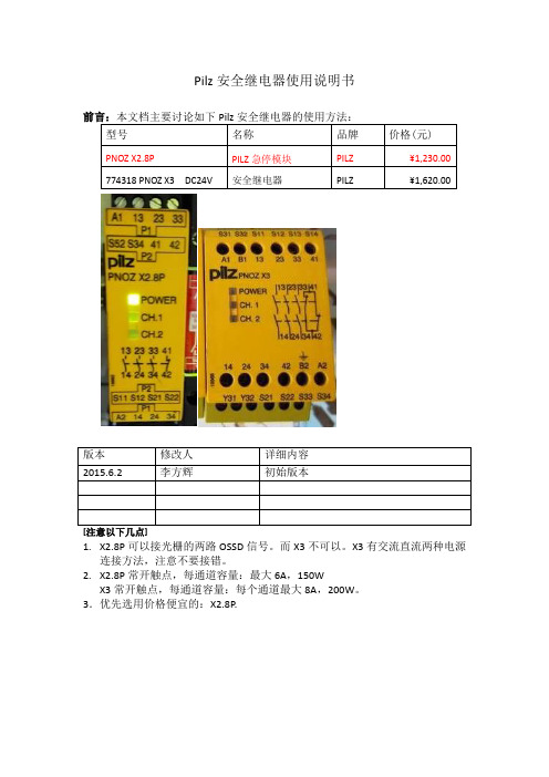
10-Pilz-X2.8P安全继电器使用说明6.2Pilz安全继电器使用说明书型号名称品牌价格(元)PNOZ X2.8P PILZ急停模块PILZ ¥1,230.00 774318 PNOZ X3 DC24V 安全继电器PILZ ¥1,620.00版本修改人详细内容2015.6.2 李方辉初始版本[注意以下几点]1.X2.8P可以接光栅的两路OSSD信号。
而X3不可以。
X3有交流直流两种电源连接方法,注意不要接错。
2.X2.8P常开触点,每通道容量:最大6A,150WX3常开触点,每通道容量:每个通道最大8A,200W。
3.优先选用价格便宜的:X2.8P.一、Pilz X2.8说明 (4)1.1 接急停开关+手动复位 (4)1.2 接光栅+手动复位 (5)二、Pilz X3的使用 (7)一、Pilz X2.8说明对于Pilz X2.8P说明:1.A1,A2为24V电源2.S21,S22; S11,S12之间接急停开关常闭触点3.S12,S34之间接复位按钮(如果不需要手动复位,希望自动复位,那么短接S12,S34即可)4.常开触点,最大6A,150W。
1.1 接急停开关+手动复位1.2 接光栅+手动复位X2.8P也可以接光栅:二、Pilz X3的使用X3的用法:1.电源的用法:可以A1,A2接交流电(220V 交流),此时B2接地线;或者B1,B2接直流电(推荐用法)。
2.双通道的用法如下:短接S11,S12; 把急停常闭触点接入S21,S22; 以及S31,S32之间。
3.每个通道最大8A,200W。
DC24V电源B 1+S A F E T Y C O N T A C T S S A F E T Y R E L A Y B 2-2S 32P I L Z :P N O Z X 3 (774 318)33233424B 2B 1S 31S 32S 22S 21S 11S 122S 221314S 33S 34-7SB2XB2BW33B1C2S 332S 342S 22-12S 32-1S e c u r i t y d o o r s41安全门开关系统启动42P 24VZ B 2B E 102CE m e r g e n c y s t o p紧急停止2S 312S 21E 24V2S 122S 12。
PLIZ 安全继电器说明书
PNOZ m1p(ETH) PNOZmulti Modular Safety SystemContents PageChapter 1Introduction1.1Validity of documentation1-11.1.1Retaining the documentation1-11.2Overview of documentation1-21.3Definition of symbols1-3Chapter 2Overview2.1Unit structure2-12.1.1Scope of delivery2-12.1.2Unit features2-12.1.3Chip card2-22.2Front view2-32.2.1PNOZ m1p2-32.2.2PNOZ m1p ETH2-32.2.3Key2-4Chapter 3Safety3.1Intended use3-13.1.1System requirements3-13.2Safety regulations3-23.2.1Use of qualified personnel3-23.2.2Warranty and liability3-23.2.3Disposal3-23.2.4For your safety3-3Chapter 4Function description4.1Unit properties4-14.1.1Integrated protection mechanisms4-14.1.2Operation4-14.1.3Block diagram4-14.1.4Diagnostics4-24.1.5Cascading4-24.1.6Safety mat, muting4-24.1.7Interfaces 4-3Chapter 5Installation5.1General installation guidelines5-15.1.1Dimensions5-25.2Install base unit without expansion module 5-35-45.3Connecting the base unit and expansionmodulesChapter 6Commissioning6.1General wiring guidelines6-16.2Ethernet interfaces (only PNOZ m1p ETH)6-26.2.1RJ45 interfaces ("Ethernet")6-26-26.2.2Requirements of the connection cable andconnector6.2.3Interface configuration6-26.2.4RJ45 connection cable6-36.2.5Process data exchange6-46.3Preparing for operation6-56.3.1Function test during commissioning6-56-56.3.2Commissioning the PNOZmulti safety sys-tem for the first time6.3.2.1Load project from chip card6-56.3.2.2Load project via integrated interface6-66.3.3Download modified project to the PNOZ-6-6multi safety system6.3.3.1Load modified project from chip card6-66.3.3.2Load modified project via integrated inter-6-6face6.3.4Connection6-76.4Connection example6-10 Chapter 7Operation7.1Messages7-17.1.1Display elements for device diagnostics 7-17-27.1.2Display elements for the Ethernet connec-tion (only PNOZ m1p ETH)7.2Reset Ethernet connection settings7-3 Chapter 8Technical details8.1Technical details8-18.2Service life graph of output relays8-58-68.3Maximum capacitive load C (μF) with loadcurrent I (mA) at the semiconductor out-puts8.4Order reference8-71.1Validity of documentationThis documentation is valid for the product PNOZ m1p. It is valid untilnew documentation is published.This operating manual explains the function and operation, describesthe installation and provides guidelines on how to connect the product .1.1.1Retaining the documentationThis documentation is intended for instruction and should be retainedfor future reference.1.2Overview of documentation1 IntroductionThe introduction is designed to familiarise you with the contents, struc-ture and specific order of this manual.2 OverviewThis chapter provides information on the product's most important fea-tures.3 SafetyThis chapter must be read as it contains important information on in-tended use.4 Function DescriptionThis chapter describes the product's mode of operation.5 InstallationThis chapter explains how to install the product.6 CommissioningThis chapter describes the product's commissioning and wiring.7 OperationThis chapter describes how to operate the product and gives tips in thecase of a fault.8 Technical DetailsThis chapter contains the product's technical details and order refer-ence.2.1.1Scope of delivery`Base unit PNOZ m1p`Terminator 779 1102.1.2Unit featuresUsing the product PNOZ m1p:Base units from the PNOZmulti modular safety systemThe product has the following features:`Can be configured in the PNOZmulti Configurator`Positive-guided relay outputs:– 2 safety outputsDepending on the application, up to PL e of EN ISO 13849-1 andup to SIL CL 3 of EN IEC 62061`Semiconductor outputs:– 4 safety outputsDepending on the application, up to PL e of EN ISO 13849-1 andup to SIL CL 3 of EN IEC 62061– 1 auxiliary output` 4 test pulse outputs` 1 cascading input and output;can also be used as a standard output`20 inputs for connecting, for example:–E-STOP pushbuttons–Two-hand buttons–Safety gate limit switches–Reset buttons–Light beam devices–Scanners–Enabling switches–PSEN–Operating mode selector switches–Pressure sensitive mats`Muting function`Connectable:–8 expansion modules on the right– 1 fieldbus module on the left– 4 expansion modules on the left`LED for:–Diagnostics–Supply voltage–Output circuits–Input circuits`Monitors shorts across the inputs through test pulse outputs`Monitors shorts between the safety outputs`Integrated interfaces:–PNOZ m1p: Serial interface RS232–PNOZ m1p ETH: 2 Ethernet interfaces`Plug-in connection terminals:either spring-loaded terminal or screw terminal available as an acces-sory (see order reference)`Coated version:Increased environmental requirements2.1.3Chip cardTo be able to use the product you will need a chip card.Chip cards are available with memories of 8 kByte and 32 kByte. Forlarge-scale projects we recommend the 32 kByte chip card (see Tech-nical Catalogue). Accessories chapter).2.2.3KeyKey:`CHIP card:–Interface chip card`X1:–Cascading inputs and outputs CI and CO,–Test pulse outputs T0 … T3`X2:–Semiconductor outputs O0 (3)–Auxiliary output OA0,–Supply connections`X3:–Relay outputs O4 and O5`X4:–RJ 232 interface / Ethernet interface`X5, X6:–Inputs I0 (I19)`X7:–Power supply`LEDs:–PWR–RUN–DIAG–FAULT–I FAULT–O FAULT3.1Intended useThe modular safety system PNOZmulti is used for the safety-related in-terruption of safety circuits and is designed for use on:`E-STOP equipment`Safety circuits in accordance with VDE0113 Part 1 and EN60204-1CAUTION!Inputs and outputs for standard functions must not be used forsafety-related applications.The coated version of the product PNOZ m1p is suitable for use wherethere are increased environmental requirements (see Technical Details).Intended use includes making the electrical installation EMC-compliant.The product is designed for use in an industrial environment. It is notsuitable for use in a domestic environment, as this can lead to interfer-ence.The following is deemed improper use in particular:`Any component, technical or electrical modification to the product`Use of the product outside the areas described in this manual`Use of the product outside the technical details (see chapter entitled“Technical Details”)3.1.1System requirementsPNOZmulti Configurator: From version:`V1.0.1 (PNOZ m1p)`V6.4.0 (PNOZ m1p ETH)Please contact Pilz if you have an older version.3.2.1Use of qualified personnelThe products may only be assembled, installed, programmed, commis-sioned, operated, maintained and decommissioned by competent per-sons.A competent person is someone who, because of their training, experi-ence and current professional activity, has the specialist knowledge re-quired to test, assess and operate the work equipment, devices,systems, plant and machinery in accordance with the general standardsand guidelines for safety technology.It is the company's responsibility only to employ personnel who:`Are familiar with the basic regulations concerning health and safety /accident prevention`Have read and understood the safety guidelines given in this descrip-tion`Have a good knowledge of the generic and specialist standards ap-plicable to the specific application.3.2.2Warranty and liabilityAll claims to warranty and liability will be rendered invalid if:`The product was used contrary to the purpose for which it is intended`Damage can be attributed to not having followed the guidelines in themanual`Operating personnel are not suitably qualified`Any type of modification has been made (e.g. exchanging compo-nents on the PCB boards, soldering work etc.).3.2.3Disposal`In safety-related applications, please comply with the mission time t Min the safety-related characteristic data.`When decommissioning, please comply with local regulations regard-ing the disposal of electronic devices (e.g. Electrical and ElectronicEquipment Act).3.2.4For your safetyThe unit meets all necessary conditions for safe operation. However,you should always ensure that the following safety requirements aremet:`This operating manual only describes the basic functions of the unit.Information on the expanded functions such as cascading can befound in the online help for the PNOZmulti Configurator and in thePNOZmulti technical catalogue. Only use these functions after youhave read and understood the documentation. All necessary docu-mentation can be found on the PNOZmulti Configurator CD.`Adequate protection must be provided for all inductive consumers.`Do not open the housing or make any unauthorised modifications.`Please make sure you shut down the supply voltage when performingmaintenance work (e.g. exchanging contactors).4.1.7InterfacesThe product PNOZ m1pETH has two Ethernet interfaces, the productPNOZ m1p has one serial interface to`Download the project`Read the diagnostic data`Set virtual inputs for standard functions`Read virtual outputs for standard functions.Information on diagnostics via the interfaces can be found in the SpecialApplications Technical Catalogue.Information on communication via Modbus/TCP can be found in the op-erating instructions "PNOZmulti Modbus".The connection to Ethernet is made via the two 8-pin RJ45 sockets.The Ethernet interface is configured in the PNOZmulti Configurator andis described in the online help for the PNOZmulti Configurator.6.1General wiring guidelinesThe wiring is defined in the circuit diagram in the Configurator. There youcan select the inputs that are to perform a particular safety function andthe outputs that will switch this safety function.Please note:CAUTION!DThe plug-in connection terminals on the relay outputs thatcarry mains voltage should only be connected and disconnectedwhen the voltage is switched off.`Information given in the “Technical details” must be followed.`Outputs:–O0 to O5 are safety outputs–O4 and O5 are relay outputs–O0 to O3 are semiconductor outputs–OA0 is an auxiliary output.`To prevent contact welding, a fuse should be connected before theoutput contacts (see technical details).`Use copper wire that can withstand 75 °C.`Sufficient fuse protection must be provided on all output contactswith inductive loads.`Power for the safety system and input circuits must always be provid-ed from a single power supply. The power supply must meet the reg-ulations for extra low voltages with safe separation.`Two connection terminals are available for each of the supply con-nections 24 V and 0 V (semiconductor outputs), plus A1 and A2 (pow-er supply). This means that the supply voltage can be looped throughseveral connections. The current at each terminal may not exceed 3A.`Test pulse outputs must exclusively be used to test the inputs. Theymust not be used to drive loads.Do not route the test pulse lines together with actuator cables withinan unprotected multicore cable.`Test pulse outputs are also used to supply safety mats that trigger ashort circuit.Test pulses that are used for the safety mat may not be reused for oth-er purposes.The Ethernet connection settings of the base unit can be configured in the PNOZmulti Configurator.You can reset the base unit's Ethernet connection settings to the default settings.Proceed as follows:`Switch off the supply voltage`Remove the chip card`Restart the base unit without the chip card inserted.The Ethernet connection settings are now reset to the default settings.Technical detailsElectrical dataSupply voltage U B DC24 VVoltage tolerance-15 %/+20 %Power consumption at U B DCwithout load8.0 W No. 773100, 7731059.0 W No. 773103, 773104per expansion module 2.50 WResidual ripple DC 5 %Status display LEDTimesSwitch-on delay 5.00 sSimultaneity channel 1/2/3 3 sTwo-hand circuit0.5 sSupply interruption before de-energisation 20 msInputsNumber20U_B > 26.4 V : 15, U_B <= 26.4 V : 20 Max. number of live inputs in the area of max. permittedambient temperature (see "Environmental data")Voltage and current at input, reset and feedback circuit24.0 V, 8.0 mAGalvanic isolation noSignal level at "0"-3 - +5 V DCSignal level at "1"15 - 30 V DCMin. pulse duration18 msPulse suppression0.6 msTest pulse outputsNumber of test pulse outputs 4Voltage and current, 24 V0.5 AOff time during self test 5 msGalvanic isolation noShort circuit-proof yesSemiconductor outputsNumber4Switching capabilityvoltage24 Vcurrent 2 Apower48 WDerating of coated version at an ambient temperature > 50°CVoltage24 V No. 773104, 773105Current 1 A No. 773104, 773105Power24 W No. 773104, 773105Max. capacitive load 1 µFExternal supply voltage24.0 VVoltage tolerance-15 %/+20 %Max. duration of off time during self test300 µsGalvanic isolation yesShort circuit-proof yesSwitch-off delay30 msResidual current at "0"0.5 mASignal level at "1"UB - 0.5 V DC bei 2 ARelay outputsNumber2Utilisation category in accordance with EN 60947-4-1Safety contacts: AC1 at240 V 6.0 A, 1440 VASafety contacts: DC1 at24 V 6.0 A, 144 WUtilisation category in accordance with EN 60947-5-1Safety contacts: AC15 at230 V 3.0 A, 690 WSafety contacts: DC13 at24 V (6 cycles/min) 3.0 A, 72 WDerating of coated version at an ambient temperature> 50 °CSafety contacts: AC1 at 240 V 4 A No. 773104, 773105, 960 W No. 773104, 773105 Safety contacts: DC1 at 24 V 4 A No. 773104, 773105, 96 W No. 773104, 773105 Airgap creepage betweenrelay contacts 3 mmrelay contacts and other safe circuits 5.5 mmExternal contact fuse protection (I K = 1 kA) toEN 60947-5-1Blow-out fuse, quick 6 ABlow-out fuse, slow 6 ACircuit breaker 24 VAC/DC, characteristic B/C 6 ASwitch-off delay50 msAuxiliary outputsNumber1Switching capabilityvoltage24 Vcurrent0.5 Apower12.0 WGalvanic isolation yesShort circuit-proof yesResidual current at "0"0.5 mASignal level at "1"UB - 0.5 V DC bei 0.5 ACascading output as auxiliary outputNumber1Switching capabilityvoltage24 Vcurrent0.2 Apower 4.8 WGalvanic isolation noShort circuit-proof yesResidual current at "0"0.5 mAEnvironmental dataEMC EN 60947-5-1Vibration to EN 60068-2-6Frequency10 - 55 HzAmplitude0.35 mmClimatic suitability EN 60068-2-1, EN 60068-2-30, EN 60068-2-78 Airgap creepage in accordance with EN 60664-1Ambient temperature-25 - 60 °C No. 773104, 7731050 - 60 °C No. 773100, 773103Storage temperature-25 - 70 °CClimatic suitability95 % r. F. No. 773104, 773105Condensation permitted No. 773104, 773105No. stands for order number.Mechanical data Protection typeMounting (e.g. cabinet)IP54Housing IP20Terminals IP20DIN rail Top hat rail 35 x 7.5 EN 50022Recess width27 mm Maximum cable runs per input1.0 km Sum of individual cable runs at the test pulse output 40 km Housing material Housing PPO UL 94 V0FrontABS UL 94 V0Cross section of external conductors with screw terminals Power supply, inputs, auxiliary output, semiconductor out-puts, test pulse outputs, cascading outputs:1 core flexible0.50 - 1.50 mm² , 22 - 14 AWG 2 core, same cross section, flexible:with crimp connectors, without insulating sleeve0.50 - 0.75 mm² , 22 - 20 AWG without crimp connectors or with TWIN crimp connectors 0.50 - 0.75 mm² , 22 - 20 AWG Relay outputs:1 core flexible0.5 - 2.5 mm², 22 - 12 AWG 2 core, same cross section, flexible:with crimp connectors, without insulating sleeve0.50 - 1.25 mm², 22 - 16 AWG without crimp connectors or with TWIN crimp connectors 0.50 - 1.25 mm², 22 - 16 AWG Torque setting with screw terminals0.25 NmCross section of external conductors with spring-loaded terminals: Flexible with/without crimp connectors0.50 - 1.50 mm² , 26 - 14 AWG Spring-loaded terminals: Terminal points per connection 1Stripping length 9 mmDimensions Height 94.0 mm Width 135.0 mm Depth 121.0 mmWeight490 g No. 773100500 g No. 773105520 g No. 773103550 g No. 773104Safety characteristic dataUnit Operating mode EN ISO 13849-1PLEN 954-1CategoryEN IEC 62061SIL CLPFH [1/h]t M [year]LogicPL e (Cat. 4)Cat. 4SIL CL 3 2.13E-1020 PL e (Cat. 4)Cat. 4SIL CL 3 2.38E-1020Requirement on 1-channel relay outputs for Cat. 2 in accordance with EN 954-1: An additional output switches to a safe condition in the event of an error or, if that is impossible, signals a hazardous condition.All the units used within a safety function must be considered when cal-culating the safety characteristic data.The standards current on 2010-10 apply.The PFH value depends on the switching frequency and the load on the relay output. If the service life graphs are not accessible, the stated PFH value can be used irrespective of the switching frequency and the load, as the PFH value already considers the relay's B10d value as well as the failure rates of the other components.CPUPL e (Cat. 4)Cat. 4SIL CL 3 4.90E-0920expansionPL e (Cat. 4)Cat. 4SIL CL 39.20E-0920Input SC inputs single-channel PL d (Cat. 2)Cat. 2SIL CL 2 2.50E-0920SC inputs dual-channelPL e (Cat. 4)Cat. 4SIL CL 3 2.90E-1020SC inputs light beam device PL e (Cat. 4)Cat. 4SIL CL 3 2.50E-1020SC inputs dual-channel pres-sure sensitive mat PL d (Cat. 3)Cat. 3SIL CL 2 1.81E-0920cascading inputsPL e (Cat. 4)Cat. 4SIL CL 3 3.10E-1020Output SC outputs single-channel PL d (Cat. 2)Cat. 3SIL CL 27.00E-0920SC outputsdual-channel PL e (Cat. 4)Cat. 4SIL CL 38.60E-1020cascading outputsPL e (Cat. 4)Cat. 4SIL CL 3 4.91E-1020relay outputs single-channel PL c (Cat. 1)Cat. 2- 2.90E-0820relay outputsdual-channelPL e (Cat. 4)Cat. 4SIL CL 33.00E-1020CAUTION!It is essential to consider the relay's service life graphs. The relay outputs' safety-related characteristic data is only valid if the val-ues in the service life graphs are met.LogicOrder referenceType Features Order no. PNOZ m1p Base unit773 100 PNOZ m1p coated version Base unit773 105 PNOZ m1p ETH Base unit773 103 PNOZ m1p ETH coated version Base unit773 104 Spring-loaded terminals 1 set783 100 Screw terminals 1 set793 10020878-E N -10, 2010-11 P r i n t e d i n G e r m a n y © P i l z G m b H & C o . K G , 2010d u r a N E T p ®, P i l z ®, P I T ®, P M C p r o te g o ®, P M I ®, P N O Z ®, P r i m o ®, P S E N ®, P S S ®, P V I S ®, S af e t y B U S p ®, S a f e t y E Y E ®, S a f e t y N E T p ®, t h e s p i r i t o f s a f e t y ® a r e r eg i s t e r e d a n d p r o t e c t e d t r a d e m a r k s P i l z G m b H & C o . K G i n s o m e c o u n t r i e s . W e w o u l d p o i n t o u t th a t p r o d u c t f e a t u r e s m a y v a r y f r o m t h e d e t ai l s s t a t e d i n t h i s d o c u m e n t , d e p e n d i n g o n t h e s t a t u s a t t h e t i m e o f p u b l i c a t i o n a n d t h e s c o p e t h e e q u i p m e n t . W e a c c e p t n o r e s p o n s i b i l i t y f o r t h e v a l i d i t y , a c c u r a c y a n d e n t i r e t y o f t h e t e x t a n d g r a p h i c s p r e s e n t e d i n t h i s i n f o r m a t i o n . P l e a s e c o n t a c t o u r T e c h n i c a l S u p p o r t i f y o u h a v e a n y q u e s t i o n s .。
Pilz安全继电器说明书大全_1[4]
![Pilz安全继电器说明书大全_1[4]](https://img.taocdn.com/s3/m/81170587970590c69ec3d5bbfd0a79563c1ed424.png)
Pilz安全继电器说明书大全_1Pilz安全继电器是用于保护人员和机器的安全设备,可以监控各种安全功能,如紧急住手、安全门、光栅、光幕、双手控制、速度和静止等。
Pilz安全继电器具有高可靠性、高性价比、高灵便性和高安全性等特点,已经在世界各地的数百万个应用场所证明了其价值。
一、Pilz安全继电器的基本原理Pilz安全继电器是一种特殊的继电器,它具有两个或者多个触点组,每一个触点组由两个串联的触点构成。
这种设计可以保证在触点发生粘连或者短路时,仍能实现断开输出回路的功能,从而达到安全目的。
Pilz安全继电器的输入端可以连接各种安全传感器或者开关,如急停按钮、安全门开关、光栅或者光幕等。
当输入端检测到异常信号时,P ilz安全继电器会即将切断输出端的电源,使被控制的机器或者设备住手运行,避免发生危(wei)险。
Pilz安全继电器的输出端可以连接各种执行元件或者指示灯,如电磁阀、接触器、继电器或者LED等。
当输出端被切断时,执行元件会失去动力,指示灯会显示故障状态,提醒操作员进行处理。
二、Pilz安全继电器的产品系列myPNOZ:具有内部组合逻辑的模块化安全继电器,可以根据用户的个性化需求进行预装配和设置,实现即插即用。
PNOZsigma:在最小的宽度上实现最大的功能,具有可调节的操作模式和时间,以及模块化设计。
PNOZX:合用于每种功能的经典安全继电器,具有机电式触点和宽电压范围。
PNOZcompact:方形、简易、黄色的基本型安全继电器,适合大批量系列机器创造商。
PNOZelog:无磨损、易于连接的半导体型安全继电器,具有扩展诊断功能。
PNOZpower:高负载(8A至16A)的输出型安全继电器,可以直接开关机电负载,并具有模块化输出触点。
三、Pilz安全继电器的功能特性国际认证:Pilz安全继电器符合国际标准和法规,如EN ISO 13849-1, IEC 62061, IEC 61508, UL, CSA等,并获得了TÜV, CE, cULus等认证。
皮尔兹安全继电器 PNOZ X2.7P使用手册

Safety relay for monitoring E-STOP pushbuttons, safety gates and light beam devicesApprovalsBlock diagram PNOZ X2.7P◆Pilz GmbH & Co. KG, Felix-Wankel-Straße 2, 73760 Ostfildern, Germany1002000-EN-06-2011-06Telephone: +49 711 3409-0, Telefax: +49 711 3409-133, E-Mail: pilz.gmbh@pilz.dePilz GmbH & Co. KG, Felix-Wankel-Straße 2, 73760 Ostfildern, Germany1002000-EN-06-2011-06Telephone: +49 711 3409-0, Telefax: +49 711 3409-133, E-Mail: pilz.gmbh@pilz.dePilz GmbH & Co. KG, Felix-Wankel-Straße 2, 73760 Ostfildern, Germany1002000-EN-06-2011-06Telephone: +49 711 3409-0, Telefax: +49 711 3409-133, E-Mail: pilz.gmbh@pilz.dePNOZ X2.7P U B 24 - 240 V AC/DCExample❝Inductive load: 0,2 A❝Utilisation category: AC15❝Contact service life: 1,000,000 cy-clesProvided the application requires few-er than 1,000,000 cycles, the PFH val-ue (see technical details) can be used in the calculation.To increase the service life, sufficient spark suppression must be provided on all output contacts. With capacitive loads, any power surges that occur must be noted. With contactors, use freewheel diodes for spark suppres-sion.Technical detailsElectrical dataSupply voltageSupply voltage U B AC/DC24 - 240 V, 24 VVoltage tolerance-15 %/+10 %Power consumption at U B AC 4.5 VA No. 777306, 7873065.5 VA No. 777305, 787305 Power consumption at U B DC 2.0 W No. 777306, 7873062.5 W No. 777305, 787305 Frequency range AC50 - 60 HzResidual ripple DC160 %Voltage and current atInput circuit DC:24.0 V25.0 mA No. 777306, 78730630.0 mA No. 777305, 787305 Reset circuit DC:24.0 V40.0 mA No. 777305, 78730550.0 mA No. 777306, 787306 Feedback loop DC:24.0 V40.0 mA No. 777305, 78730550.0 mA No. 777306, 787306 Number of output contactsSafety contacts (S) instantaneous:3Auxiliary contacts (N/C):1PNOZ X2.7P1002000-EN-06-2011-06Pilz GmbH & Co. KG, Felix-Wankel-Straße 2, 73760 Ostfildern, GermanyTelephone: +49 711 3409-0, Telefax: +49 711 3409-133, E-Mail: pilz.gmbh@pilz.deUtilisation category in accordance with EN 60947-4-1Safety contacts: AC1 at 240 V I min :0.01 A , I max :6.0 A P max : 1500 VASafety contacts: DC1 at 24 V I min : 0.01 A , I max : 6.0 A P max : 150 WAuxiliary contacts: AC1 at 240 V I min : 0.01 A , I max : 6.0 A P max : 1500 VAAuxiliary contacts: DC1 at 24 VI min : 0.01 A , I max : 6.0 A P max : 150 WUtilisation category in accordance with EN 60947-5-1Safety contacts: AC15 at 230 VI max : 3.0 A No. 777306, 7873065.0 A No. 777305, 787305Safety contacts: DC13 at 24 V (6 cycles/min)I max : 4.0 A No. 777306, 7873065.0 A No. 777305, 787305Auxiliary contacts: AC15 at 230 VI max : 3.0 A No. 777306, 7873065.0 A No. 777305, 787305Auxiliary contacts: DC13 at 24 V (6 cycles/min)I max : 4.0 A No. 777306, 7873065.0 A No. 777305, 787305Contact materialAgCuNi + 0.2 µm AuExternal contact fuse protection (I K = 1 kA) to EN 60947-5-1Blow-out fuse, quick Safety contacts:10 A No. 777305, 7873056 A No. 777306, 787306Auxiliary contacts:10 A No. 777305, 7873056 A No. 777306, 787306Blow-out fuse, slow Safety contacts: 4 A No. 777306, 7873066 A No. 777305, 787305Auxiliary contacts:4 A No. 777306, 7873066 A No. 777305, 787305Circuit breaker 24 VAC/DC, characteristic B/C Safety contacts: 4 A No. 777306, 7873066 A No. 777305, 787305Auxiliary contacts:4 A No. 777306, 7873066 A No. 777305, 787305Max. overall cable resistance R lmax input circuits, reset circuits single-channel at U B DC 30 Ohm No. 777305, 78730545 Ohm No. 777306, 787306single-channel at U B AC100 Ohm No. 777305, 78730545 Ohm No. 777306, 787306dual-channel without detect. of shorts across contacts at U B DC 50 Ohm No. 777305, 78730580 Ohm No. 777306, 787306dual-channel without detect. of shorts across contacts at U B AC 100 Ohm No. 777305, 78730580 Ohm No. 777306, 787306dual-channel with detect. of shorts across contacts at U B DC 15 Ohm dual-channel with detect. of shorts across contacts at U B AC 15 OhmMin. input resistance when switching on141 Ohm No. 777306, 78730671 Ohm No. 777305, 787305Safety-related characteristic dataPL in accordance with EN ISO 13849-1: 2006PL e (Cat. 4)Category in accordance with EN 954-1Cat. 4SIL CL in accordance with EN IEC 62061SIL CL 3PFH in accordance with EN IEC 62061 2.31E-09SIL in accordance with IEC 61511SIL 3PFD in accordance with IEC 615112.03E-06T M [year] in accordance with EN ISO 13849-1: 200620Electrical dataPNOZ X2.7PTimesSwitch-on delayon monitored reset with rising edge typ.30 mson monitored reset with rising edge max.40 ms No. 777306, 78730650 ms No. 777305, 787305Delay-on de-energisationwith E-STOP typ.10 ms No. 777306, 78730615 ms No. 777305, 787305with E-STOP max.20 ms No. 777306, 78730630 ms No. 777305, 787305with power failure typ.60 ms No. 777305, 787305with power failure max.100 ms No. 777305, 787305with power failure typ. U B AC/DC:24 V No. 777306, 787306180 ms No. 777306, 787306with power failure max. U B AC/DC:24 V No. 777306, 787306230 ms No. 777306, 787306with power failure typ. U B AC: 240 V1,100 ms No. 777306, 787306with power failure max. U B AC: 240 V1500 ms No. 777306, 787306Recovery time at max. switching frequency 1/safter E-STOP50 msafter power failure200 ms No. 777305, 787305250 ms No. 777306, 787306after power failure on universal power supply 1500 ms No. 777306, 787306Waiting period with a monitored resetwith rising edge250 ms No. 777305, 787305300 ms No. 777306, 787306Min. start pulse duration with a monitored resetwith rising edge30 msSimultaneity, channel 1 and 2∞Supply interruption before de-energisation 20 msEnvironmental dataEMC EN 60947-5-1, EN 61000-6-2, EN 61000-6-4 Vibration to EN 60068-2-6Frequency10 - 55 HzAmplitude0.35 mmClimatic suitability EN 60068-2-78Airgap creepage in accordance with EN 60947-1Pollution degree2Overvoltage category III / IIRated insulation voltage250 VRated impulse withstand voltage 4.00 kVAmbient temperature-10 - 55 °C No. 777306, 787306-35 - 55 °C No. 777305, 787305Storage temperature-40 - 85 °CProtection typeMounting (e.g. cabinet)IP54Housing IP40Terminals IP20Mechanical dataHousing materialHousing PPO UL 94 V0Front ABS UL 94 V0Cross section of external conductors with screw terminals1 core flexible0.25 - 2.50 mm² , 24 - 12 AWG No. 777305, 7773062 core, same cross section, flexible:with crimp connectors, without insulating sleeve0.25 - 1.00 mm² , 24 - 16 AWG No. 777305, 777306 without crimp connectors or with TWIN crimp connectors0.20 - 1.50 mm² , 24 - 16 AWG No. 777305, 777306 Torque setting with screw terminals0.50 Nm No. 777305, 777306Cross section of external conductors with spring-loaded termi-0.20 - 1.50 mm² , 24 - 16 AWG No. 787305, 787306 nals: Flexible with/without crimp connectorsPNOZ X2.7P1002000-EN-06-2011-06Pilz GmbH & Co. KG, Felix-Wankel-Straße 2, 73760 Ostfildern, GermanyTelephone: +49 711 3409-0, Telefax: +49 711 3409-133, E-Mail: pilz.gmbh@pilz.deNo. stands for order number.It is essential to consider the relay's service life graphs. The relay outputs' safety-related characteristic data is only valid if the values in the service life graphs are met.The PFH value depends on the switch-ing frequency and the load on the relay output.If the service life graphs are not acces-sible, the stated PFH value can be used irrespective of the switching fre-quency and the load, as the PFH value already considers the relay's B10d val-ue as well as the failure rates of the other components.All the units used within a safety function must be considered when calculating the safety characteristic data.The standards current on 2009-12 apply.Spring-loaded terminals: Terminal points per connection 2 No. 787305, 787306Stripping length 8 mm No. 787305, 787306Dimensions Height 101.0 mm No. 787305, 78730694.0 mm No. 777305, 777306Width 22.5 mm Depth 121.0 mmWeight190 g No. 777305, 787305205 g No. 787306210 g No. 777306Mechanical dataConventional thermal current Number of contacts I th (A) at U B DC I th (A) at U B AC 1 6.00 A 6.00 A2 6.00 A4.00 A No. 777305, 7873056.00 A No. 777306, 78730634.50 A No. 777306, 7873065.00 A No. 777305, 7873053.50 A No. 777305, 7873054.50 A No. 777306, 787306Order reference TypeFeatures TerminalsOrder no.PNOZ X2.7P C 24 VAC 24VDC Spring-loaded terminals 787 305PNOZ X2.7P 24 VAC24VDCScrew terminals777 305PNOZ X2.7P C 24 - 240 VAC 24 - 240 VDC Spring-loaded terminals 787 306PNOZ X2.7P24 - 240 VAC24 - 240 VDCScrew terminals777 306。
10_Pilz X2.8P安全继电器使用说明6.2
Pilz安全继电器使用说明书
774318 PNOZ X3 DC24V安全继电器PILZ¥1,620.00
[注意以下几点]
1.X
2.8P可以接光栅的两路OSSD信号。
而X3不可以。
X3有交流直流两种电源
连接方法,注意不要接错。
2.X2.8P常开触点,每通道容量:最大6A,150W
X3常开触点,每通道容量:每个通道最大8A,200W。
3.优先选用价格便宜的:X2.8P.
一、Pilz X2.8说明 (3)
1.1 接急停开关+手动复位 (3)
1.2 接光栅+手动复位 (4)
二、Pilz X3的使用 (5)
一、Pilz X2.8说明
对于Pilz X2.8P说明:
1.A1,A2为24V电源
2.S21,S22;S11,S12之间接急停开关常闭触点
3.S12,S34之间接复位按钮(如果不需要手动复位,希望自动复位,那么
短接S12,S34即可)
4.常开触点,最大6A,150W。
1.1 接急停开关+手动复位
1.2 接光栅+手动复位X
2.8P也可以接光栅:
二、Pilz X3的使用
X3的用法:
1. 电源的用法:可以A1,A2接交流电(220V 交流),此时B2接地线; 或者B1,B2接直
流电(推荐用法)。
2. 双通道的用法如下:
短接S11,S12; 把急停常闭触点接入S21,S22; 以及S31,S32之间。
3.每个通道最大8A ,200W 。
S e c u r i t y d o o r s
安全门开关
E m e r g e n c y s t o p
紧急停止。
皮尔磁安全继电器说明书
皮尔磁安全继电器说明书摘要:1.皮尔磁安全继电器的概述2.皮尔磁安全继电器的工作原理3.皮尔磁安全继电器的功能与应用4.皮尔磁安全继电器的优点与安全保障5.皮尔磁安全继电器的日常维护与注意事项正文:一、皮尔磁安全继电器的概述皮尔磁安全继电器是一种具有高安全性能的电气设备,它主要由数个继电器与电路组合而成。
其目的是为了互补彼此的异常缺陷,达到正确且低误动作的继电器完整功能,使其失误和失效值愈低,安全因素则愈高。
因此,皮尔磁安全继电器广泛应用于保护不同等级机械的电气设备控制系统中,尤其是在国外的进口设备中更为常见。
二、皮尔磁安全继电器的工作原理皮尔磁安全继电器的工作原理主要基于互补原理,即通过数个继电器之间的组合,实现对电气设备的监控和控制。
当电气设备发生异常时,继电器能够及时发出信号,停止设备的运行,从而保护操作人员的安全。
同时,皮尔磁安全继电器还具有低误动作的特性,能够有效避免因误操作而导致的设备停机,提高生产效率。
三、皮尔磁安全继电器的功能与应用皮尔磁安全继电器具有多种功能,如过载保护、短路保护、过压保护等。
这些功能使其成为保护不同等级机械的理想选择。
在实际应用中,皮尔磁安全继电器主要应用于电气设备控制系统,如自动化生产线、机器人、电梯等设备,以确保操作人员的安全。
四、皮尔磁安全继电器的优点与安全保障皮尔磁安全继电器具有以下优点:1.高安全性能:通过互补原理,实现低误动作,提高设备的安全性。
2.灵活性:可以根据不同的应用场景选择合适的继电器,实现多种保护功能。
3.可靠性:采用高质量的材料和制造工艺,确保设备的长期稳定运行。
4.易于维护:具有明确的指示灯和故障诊断功能,便于操作人员进行日常维护和故障排查。
五、皮尔磁安全继电器的日常维护与注意事项为了确保皮尔磁安全继电器的正常运行和延长使用寿命,操作人员应注意以下几点:1.定期检查继电器的运行状态,如有异常声音、温度过高等现象,应及时停机检查。
2.保持继电器及其周围环境的清洁,避免灰尘、油污等杂物影响设备的运行。