Power steering
Honda Power Steering Fluid说明书

CONNECTOR HOLD-DOWN WIRE Low Beam Headlight
1. Remove the electrical connector from the bulb by pulling the connector straight back.
2. Remove the rubber weather seal by pulling on the tab.
WEATHER SEAL
BULB
Halogen headlight bulbs get very hot when lit. Oil, perspiration, or a scratch on the glass can cause the bulb to overheat and shatter.
Turning the steering wheel to f ull lef t or right lock and holding it there can damage the power steering pump.
190
v w
Main Menu
Table of Contents
Lights
4. Install the new bulb into the hole, making sure the tabs are in their slots. Pivot the hold-down wire back in place, and clip the end into the slot.
Pour the fluid slowly and carefully so you do not spill any. Clean up any spills immediately; it could damage components in the engine compartment.
汽车转向系统英语词汇 汽车英语词汇
汽车转向系统词汇转向系steering system类型type机械转向系manual steering system动力转向系power steering system转向操纵机构steering control mechanism直列式转向器in-line steering gear四边联杆式转向机构parallelogram linkage steering 整体式动力转向机构integral type power steering 总成和部件assemblies and parts转向万向节steering universal joint转向传动轴steering inner articulated shaft转向管柱steering column球轴承套管式转向管柱tube and ball typesteering column可伸缩式转向管柱telescopic steering column 折叠式转向管柱collapsible steering column 倾斜和缩进式转向管柱tilt and telescopic steering column 吸能式转向管柱energy-absorbing steering column网络状转向柱管net type steering column转向轴steering shaft转向横轴cross shaft转向盘steering wheel倾斜式方向盘tilt steering wheel机构转向器manual steering gear蜗杆滚轮式转向器worm and roller steering gear 转向器盖cover of steering gear壳体housing转向蜗杆steering worm滚轮roller滚轮轴roller shaft侧盖side cover摇臂轴pitman arm shaft循环球式转向器recirculating ball steering gear 循环球和螺母式转向器recirculating ball and nut steering gear 循环球齿条齿扇式转向器recirculating ball-rack and sector steering gear转向螺母steering nut钢球ball转向螺杆steering screw循环球-曲柄销式转向器recirculating ball-leverand peg steering gear指销stud蜗杆指销式转向器worm and peg steering gear转向齿轮steering pinion转向齿条steering rack动力转向器power steering gear整体式动力转向器integral power steering gear常压式液压动力转向器constant pressure hydraulic power steering gear常流式液压动力转向器constant flow hydraulic power steering gear螺杆螺线式转向器screw and nut steering gear 蜗杆指销式转向器worm and peg steering gear 齿轮齿条式转向器rack and pinion steering gear 变传动比转向器steering gear with variable ratio 转向掌握阀steering control valve 滑阀式转向掌握器spool valve type 阀体valve housing 滑阀valve spool转阀式转向掌握阀rotary valve type扭杆torsion bar转向动力缸power cylinder转向油泵power steering pump转向油罐oil reservoir转向传动杆系steering linkage动力转向系布置power steering system layout反作用阀reactive valve梯形转向机构Ackerman steering整体式转向梯形杆系Ackerman steeringlinkages分段式转向梯形杆系divided Ackerman steeringlinkage中间转向杆intermediate steering rod转向摇臂pitman arm转向直拉杆steering drag link 中间转向联杆center steering linkages端部螺塞end plug球头销ball stud球头座ball cup压缩弹簧compression spring梯形机构tie rod linkage梯形臂tie rod arm转向横拉杆steering tie rod接头socket横拉杆端接头ti© rod end分段式梯形机构split tie rod type tie rod linkage摆臂swing arm动力转向power steering气压式动力转向air-power steering液压式动力转向hydraulic power steering 液压常流式动力转向hydraulic constant flow type power steering液压储能式动力转向hydraulic accumulator power steering慢速转向slow steering快速转向fast steering (quick steering)过度转向oversteering转向缺乏understeering转向系刚度steering system stiffness方向盘自由行程free play of steering wheel转向器转动力矩rotating torque of steering gear 转向力矩steering moment转向阻力矩steering resisting torque 转向力steering force转向传动比steering gear ratio (steering ratioO 恒定转向传动比constant ratio steering 可变转向传动比variable ratio steering 转向系角传动比steering system angle ratio 转向器角传动比steering gear angle ratio 转向传动机构角传动比steering linkage angle ratio转向器传动效率steering gear efficiency 正效率forward efficiency 逆效率reverse efficiency转向器扭转刚度torsional stiffness of steering gear转向盘总圈数total number of steering wheel turns转向器总圈数total turns of steering gear转向器传动间隙steering gear clearance摇臂轴最大转角max.rotating angle of pitman arm shaft转向摇臂最大摆角max. Swing angle of steering pitman arm转向器反驱动力矩reverse rotating torque of steering gear转向器最大输出扭矩steering gear max. Output torque最大工作压力max. Working pressure 额定工作压力rated working pressure 转向油泵理论排量theoretical displacement ofpump限制流量limited flow转向掌握阀预开隙pre-opened play of steering control valve转向掌握阀全开隙totally -opened play of steering control valve转向掌握阀内泄漏量internal leakage in steering control valve转向掌握阀压力降pressure loss in steeringcontrol valve转向器角传动比特性steering gear angle ratio characteristic转向器传动间隙特性steering gear clearance characteristic转向器传动效率特性steering gear efficiency characteristic转向力特性steering force characteristic 动力转向系灵敏度特性power steering system response characteristic转向掌握阀压力降特性steeringcontrol valve pressure loss characteristic 前桥front axle工字梁I-beam双工字梁twin I-beam非驱动桥dead axle转向节steering knuckle挂车转向装置steering system of trailer中心主销式转向装置central king pin type steering system无主销转向装置no king pin type steering system 全杆式转向装置all linkage type steering system 球销式转向节ball and socket steering knuckle 转向节止推轴承steering knuckle thrust bearing 前轮轴front wheel spindle转向盘轴steering spindle 转向节轴knuckle spindle转向节臂steering knuckle arm(转向节)主销knuckle pin(King pin)反拳式前桥reverse elliott axle反拳式转向节reverse elliott steering knuckle 叉式前桥elliott type axle叉式转向节elliott steering knuckle。
汽车转向系英语词汇
汽车转向系英语词汇汽车转向系英语词汇摆臂swing arm变传动比转向器steering gear with variable ratio侧盖side cover常流式液压动力转向器constant flow hydraulic power steering gear常压式液压动力转向器constant pressure hydraulic power steering gear 齿轮齿条式转向器rack and pinion steering gear动力转向power steering动力转向器power steering stgear动力转向系power steering system动力转向系布置power steering system layout端部螺塞end plug阀体valve housing反作用阀reactive valve分段式梯形机构split tie rod type tie rod linkage分段式转向梯形杆系divided ackerman steering linkage钢球ball 滚轮roller滚轮轴roller shaft过度转向oversteering横拉杆端接头tie rod end滑阀valve spool滑阀式转向掌握器spool valve type机构转向器manual steering gear机械转向系manual steering system接头socket壳体housing可伸缩式转向管柱telescopic steering column快速转向fast steering (quick steering)类型type螺杆螺线式转向器screw and nut steering gear慢速转向slow steeirng扭杆torsion bar气压式动力转向air-power steering倾斜和缩进式转向管柱tilt and telescopic steering column倾斜式方向盘tilt steering wheel球头销ball stud球头座ball cup球轴承套管式转向管柱tube and ball type steering column四边联杆式转向机构parallelogram linkage steering梯形臂tie rod arm梯形机构tie rod linkage梯形转向机构ackerman steering网络状转向柱管net type steering column蜗杆滚轮式转向器worm and roller steering gear蜗杆指销式转向器worm and peg steering gear蜗杆指销式转向器worm and peg steering gear吸能式转向管柱energy-absorbing steering column循环球齿条齿扇式转向器recirculating ball-rack and sector steering gear 循环球和螺母式转向器recirculating ball and nut steering gear循环球-曲柄销式转向器recirculating ball-lever and peg steering gear循环球式转向器recirculating ball steering gear压缩弹簧compression spring摇臂轴pitman arm shaft液压常流式动力转向hydraulic constant flow type power steering液压储能式动力转向hydraulic accumulator power steering液压式动力转向hydraulic power steerig折叠式转向管柱collapsiblesteering column整体式动力转向机构integral type power steering整体式动力转向器integral power steering gear整体式转向梯形杆系ackerman steering linkdage直歹U式转向器in-line steering gear指销stud中间转向杆intermediate steering rod中间转向联杆center steering linkdage转阀式转向掌握阀rotary valve type转向缺乏understeering转向操纵机构steering control mechanism转向齿轮steering pinion转向齿条steering rack转向传动杆系steering linkage转向传动轴steering inner articulated shaft转向动力缸power cylinder 转向管柱steering column转向横拉杆steering tie rod转向横轴cross shaft转向掌握阀steering control valve转向力矩steering mometn转向螺杆steering screw转向螺母steering nut转向盘steering wheel转向盘自由行程free play of steering wheel转向器盖cover of steering gear转向器转动力矩rotating torque of steering gear转向万向节steering universal joint转向蜗杆steering worm转向系steering system转向系冈U度steering system stiffness转向摇臂pitman arm转向油泵power steerig pump转向油罐oil reservoir转向直拉杆steering drag link转向轴steering shaft转向阻力矩steering resisting torque总成和部件assemblies and parts。
P-Eps(PinionElectricPowerSteering)齿轮式电动助力转向系统
P-Eps (Pinion Electric Power Steering) 齿轮式电动助力转向系统EPS,电动助力转向。
也可以叫EPAS。
其最大优点是可以随速控制助力,在低速时提供较大助力,保证轻便转向;在高速时减小助力,提供驾驶员足够的路感。
EPS只在转向时发挥作用,因此不像液压转向会一直对发动机造成额外负担,从而减小油耗,同时没有不可回收件,更加绿色,从各方面满足环保的需求。
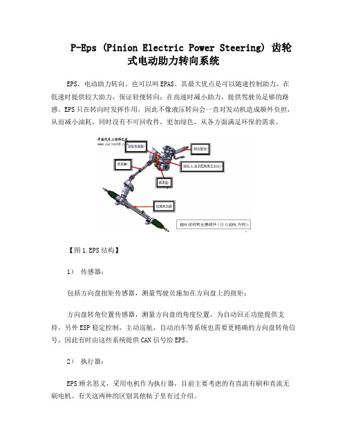
【图1.EPS结构】1)传感器:包括方向盘扭矩传感器,测量驾驶员施加在方向盘上的扭矩;方向盘转角位置传感器,测量方向盘的角度位置,为自动回正功能提供支持,另外ESP稳定控制,主动巡航,自动泊车等系统也需要更精确的方向盘转角信号,因此有时由这些系统提供CAN信号给EPS。
2)执行器:EPS顾名思义,采用电机作为执行器,目前主要考虑的有直流有刷和直流无刷电机。
有关这两种的区别其他帖子里有过介绍。
3)减速机构:电机输出的扭矩经过减速机构加载到转向系统上。
形式有蜗轮蜗杆式,循环球式,差动轮系和摇臂机构等等,前两者比较常见,也跟EPS的形式有关(参见EPS分类)。
4)电子控制单元:EPS的电子控制单元可以跟车上其他部件通信,处理传感器信号,通过程序计算出需要的助力大小,并转换成控制信号输出给驱动电路,驱动电动机输出扭矩。
5)转向机构:跟常规转向机构类似。
EPS的分类:主要分3大类,根据电机在转向机构中耦合位置和方式的不同。
1) C-EPS转向柱式(Column Electric Power Steering):直接在转向柱上安装,可以从常规转向改进而来,简单,成本低;缺点是噪音大,振动不好控制,会直接传到方向盘上,传递扭矩也较小。
2) P-EPS小齿轮式(Pinion Electric Power Steering):结构较紧凑,且提高了系统的刚度;但电子部分工作环境差(安装位置距离前桥近),要求耐温,防水,抗干扰等性能高,提高了成本。
汽车转向系术语和定义

汽车转向系术语和定义
汽车转向系术语和定义是关于汽车转向系统的专业术语和其对应的解释或定义。
转向系统是汽车的重要组成部分,负责控制车辆的方向。
以下是一些汽车转向系的术语和定义:
1.转向盘(Steering Wheel):驾驶员用来操作转向器的部件,通常位于驾
驶员的左手边。
2.转向柱(Steering Column):连接转向器和转向盘的柱状结构,可以调
整长度和倾斜角度。
3.转向器(Steering Gear):将转向盘的转动转化为转向轴的转动,从而控
制车轮转向的装置。
4.转向节(Steering Knuckle):车轮连接处的金属部件,包含转向轴,使
车轮能够围绕它进行转向。
5.转向拉杆(Steering Linkage):连接转向节和转向器的金属杆,通过其
长度调整可以改变车辆的转向半径。
6.助力转向(Power Steering):一种系统,通过增加驾驶员在转向盘上的
力来减小转向力,通常由液压或电动马达提供动力。
7.主动转向(Active Steering):一种系统,可以通过电子控制改变转向比,
以提供更好的操控性和稳定性。
总结来说,汽车转向系术语和定义是关于汽车转向系统的专业术语和其对应的解释或定义。
这些术语和定义有助于人们更好地理解汽车转向系统的结构和功能。
双齿轮电动助力转向系统教学讲义

Electric power steering Steering angle sensor
Function
F317_092
宝速来腾宝的ES来传P内感车圈器等的内分圈方6分0份向为,五盘因块此转,不但角能每识块传别间感出距转不器过同整G,8圈所5之以后可的以差快别速,识所别以出需转要角整变圈化计以数及器可,以记忆转过的圈数。
主动回正功能:
1、如果驾驶员在转弯的过程中减少了施加在方向盘 上的力,旋转杆上的扭转也相应减少。
2、转向力的减少的同时,包括转向角度和转向的速 度都相应的减少,一个精确的回转速度也相应的计 算出来。将其和转向角度和速度进行比较,其结果 就是需要的回正力。
3、作用在方向盘上的转向回正力是由整个运动装置 设计的结果,转向回正力经常很微弱,因为转向系 统及悬挂系统的摩擦力就可以使车轮回到中心位置。
所有黑色的元件可以更换 电机和控制单元也可以个别更换,但现在不考虑
电子机械动力转向系统元件组成图:
转向小齿轮 转向力矩传感器G269
ቤተ መጻሕፍቲ ባይዱ
黑色的可以单独更换
动力转向控 制单元J500
电子动力转 向电机V187
蠕动齿轮
驱动小齿轮
J104
G28
G44-G47
J220/J248
J533数据总线诊断接口
J527转向柱电子 控制单元
J285组合仪表
G85 K161故障指示灯
15#正电
J500电子助力转向控制单元
G269转向力矩传感器
V187电子助力转向电机
输入信号 输出信号 CAN
如何转向助力是通过存储在控 制单元中的不变的特性图程序 控制的,控制单元中最多可存 储16种不同的特性图。特性图是 在生产厂根据不同的整车装 备 分别设置的(如整车重量)。 GOLF2004中放置了8中特性图。 CADDY中放置了 如果控制单元或转向系统发生 了改变时,可以用VAS5051通 过功能“adaption”中的01通道 进行匹配。
Electric power steering(EPS)电动助力转向机
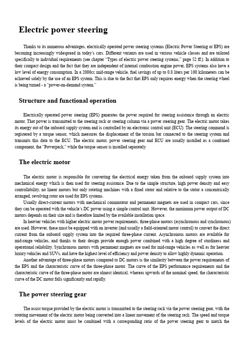
Electric power steeringThanks to its numerous advantages, electrically operated power steering systems (Electric Power Steering or EPS) are becoming increasingly widespread in today’s cars. Different variants are used in various vehicle classes and are tailored specifically to individual requirements (see chapter “Types of electric power steering systems,” page 52 ff.). In addition to their compact design and the fact that they are independent of internal combustion engine power, EPS systems also have a low level of energy consumption. In a 2000cc mid-range vehicle, fuel savings of up to 0.8 liters per 100 kilometers can be achieved solely by the use of an EPS system. This is due to the fact that EPS only requires energy when the steering wheel is being turned - a “power-on-demand system.”Structure and functional operationElectrically operated power steering (EPS) generates the power required for steering assistance through an electric motor. That power is transmitted to the steering rack or steering column via a power steering gear. The electric motor takes its energy out of the onboard supply system and is controlled by an electronic control unit (ECU). The steering command is registered by a torque sensor, which measures the displacement of the torsion bar connected to the steering system and transmits this data to the ECU. The electric motor, power steering gear and ECU are usually installed as a combined component, the “Powerpack,” while the torque sensor is installed separately.The electric motorThe electric motor is responsible for converting the electrical energy taken from the onboard supply system into mechanical energy which is then used for steering assistance. Due to the simple structure, high power density and easy controllability, no linear motors but only rotating machines with a fixed stator and relative to the stator a concentrically arranged, revolving rotor are used for EPS systems.Usually direct-current motors with mechanical commutator and permanent magnets are used in compact cars, since they can be operated with the vehicle’s DC power using a simple control unit. However, the maximum power output of DC motors depends on their size and is therefore limited by the available installation space.In heavier vehicles with higher electric motor power requirements, three-phase motors (asynchronous and synchronous) are used. However, these must be equipped with an inverter (and usually a field-oriented motor control) to convert the direct current from the onboard supply system into the required three-phase current. Asynchronous motors are available for mid-range vehicles, and thanks to their design provide enough power combined with a high degree of sturdiness and operational reliability. Synchronous motors with permanent magnets are used for mid-range vehicles as well as for heavier luxury vehicles and SUVs, and have the highest level of efficiency and power density to allow highly dynamic operation.Another advantage of three-phase motors compared to DC motors is the similarity between the power requirements of the EPS and the characteristic curve of the three-phase motor. The curve of the EPS performance requirements and the characteristic curve of the three-phase motor are almost identical, whereas upwards of the nominal speed, the characteristic curve of the DC motor falls significantly and rapidly.The power steering gearThe assist torque provided by the electric motor is transmitted to the steering rack via the power steering gear, with the rotating movement of the electric motor being converted into a linear movement of the steering rack. The speed and torque levels of the electric motor must be combined with a corresponding ratio of the power steering gear to match theperformance requirements of the steering system. Worm gears, ball and nut gears and toothed belt gears are used in EPS systems.In the case of a worm gear, the worm, which is shaped like a threaded bolt, engages in the worm wheel, which has teeth on its surface for that purpose. Worms used for EPS applications are made of hardened steel, but the teeth of the worm wheel are produced from high-performance plastic to reduce operating noise. Worm gears permit a large ratio with only one stage, but their efficiency level is not optimal.With an efficiency level of well over 90%, the ball and nut gear is considerably more efficient and also has a large ratio and a high level of mechanical stability. Ball and nut gears consist of a ball screw, an endless ball chain as a rolling element and a ball screw nut, including the return system for the ball chain and sealing elements. In EPS systems, the ball screw is designed as part of the steering rack, and the ball screw nut - referred to in these applications as a steering nut - is mounted around the ball screw via a ball bearing. The ball and nut gear is driven by the electric motor either directly or via a belt and pulley, where the steering nut rotates around the steering rack and the interposed ball chain converts the rotating motion into a linear motion of the steering rack.The additional interposition of a toothed belt gear into the ball and nut gear permits a second transmission stage, the ratio of which results from the size ratio of the two toothed disks.The electronic control unit (ECU)To control the electric motor, the EPS system has an ECU which calculates the necessary level of power assist through signal processing electronics and then supplies the requisite motor current via power electronics. A distinction is made between interior-mounted and engine compartment control units, mainly because of their temperature resistance, impermeability and resistance to various media such as oil, salt, etc., to which they are more (engine compartment units) or less (interior-mounted units) exposed.Preferably direct-mounted control units are being used, if possible in close proximity to the electric motor. In this way only short connection cables and fewer connectors are required, which reduces line losses and requires considerably less wiring. A stand-alone control unit is only installed in vehicles which do not have sufficient installation space available near the electric motor.To calculate the required level of power assist, the signal processing depends mainly on the information from the torque sensor. But the system is also connected to other ECUs in the vehicle via BUS interfaces, for example to the electronic stability program (ESP).This allows the detailed information about the current driving condition of the vehicle to be evaluated and processed by means of intelligent control and regulation algorithms. In this way a more refined control of the power assist level becomes possible.This can be used to adjust the required steering wheel torque (applied by the driver) to the current driving state, for example with a comfortable driving style, a lower steering wheel torque is required, while for a faster and sporty style, a higher torque will be necessary.The torque sensorA key parameter for calculation of the necessary power assist level in EPS systems is the steering wheel torque which the driver applies to the steering system by turning the steering wheel. This torque must be very precisely determined to give the driver a good steering feel and reassure him that his steering command is being directly implemented.Currently, only torque sensors with a mechanical torsion bar are used in EPS systems. They differ mainly in the method of measurement with which the torsion bar’s angle of rotation is determined during a steering operation. Torque sensors are available with potentiometric, inductive, magnetic and optical measurement, whereby because potentiometric sensors are not contactless and are thus subject to wear, they are only used nowadays for very low-cost EPS systems in com-pact cars.Inductive and magnetic measurement methods are based on measurement of magnetic field changes. In the case ofinductive measurement, the measurement takes place in an alternating magnetic field, while magnetic measurement is carried out in a static magnetic field. The advantages of both of these systems are that they use non-contact and therefore wear-free components, that they have a high degree of accuracy, and that they are impervious to dirt, water and oil.Optical measurement is performed using a light-emitting transmitter, for example an LED, and a light-sensitive receiver, for example a photodiode. A structured code disk, for example a stamped grid plate, is located between the transmitter and the receiver. The rotation of the torsion bar affects the light intensity between the transmitter and the receiver, and this change can be measured and evaluated in order to calculate the steering wheel torque. The advantage of optical sen-sors lies in their imperviousness to electro- magnetic interference. They are however very sensitive to contamination and to mechanical stress, so they can only be used within a limited temperature range.Types of electric power steering systemsThe types of electric power steering (EPS) systems differ in the location in which the servo unit is installed in the steering system. This is why they are called EPSc, EPSp, EPSdp, EPSapa and EPSrc - the lower-case suffixes describe the installation locations.EPSc - servo unit on the steering column (column)The first electric power steering system, the EPSc, was launched in the late 1980s and remains the most widely used EPS system in compact and mid-range vehicles. The servo unit including the torque sensor is located on the steering column and thus in the vehicle interior. This protects it from the environment; for example, it does not have to be waterproof and it is exposed to significantly lower temperature effects than those which exist in the engine compartment. One disadvantage here is, however, its proximity to the driver and the excessive distance to the steering gear.Its proximity to the driver can have an impact on safety if an accident occurs, because the distance to the steering gear results in a long transmission path for the forces via steering column, intermediate shaft and steering pinion. This limits the maximum achievable steering output. The assist torque from the electric motor to the steering column is generally transmitted via a worm gear.EPSp - servo unit on the steering pinion (pinion)In the EPSp, the assist torque of the electric motor is also transmitted by means of a worm gear, which in this case is directly connected to the steering pinion and the steering rack. This design eliminates the long transmission path, permitting higher steering forces compared to the EPSc. This design also enables the torque sensor to be directly combined with the servo unit.The installation options of the EPSp are subject to certain limitations, since the servo unit can only be rotated around the axis of the steering pinion. Furthermore, it is located in the driver’s footwell, so it needs to be ensured that the EPSp cannot penetrate into this area if an accident occurs, since this could lead to injury.Its position on the steering pinion means of course that the EPSp is located in the engine compartment, so it must meet higher demands regarding water tightness as well as resistance to temperature and vibration in this location. This also applies to all the types described below.EPSdp - servo unit on a second steering pinion (dual pinion)The limited installation options and the problematic accident safety issues of the EPSp led to development of the EPSdp design. Incorporating a second pinion into the steering system made it possible to place the sensor and the drive unit apart from one another. The torque sensor of the EPSdp is mounted on the actual steering pinion, from where it measuresthe steering wheel torque. The servo unit itself transmits the assist torque, but to the second pinion. Thanks to an appropriate worm gear design, the position of the servo unit relative to the rack-and-pinion and drive pinion axes can be adapted as required to fit the available installation space and to meet accident safety requirements.Another positive side-effect of this solution is a further increase in steering performance. The fact that the drive pinion ratio is independent of the steering ratio permitted the design of a performance-optimized drive ratio.EPSapa - servo unit with axis-parallel drive of the steering rack (axis parallel)A low level of system friction and a high degree of efficiency characterize the EPSapa design. This is why it is mainly used in vehicles with high steering assist requirements, such as sports cars, SUVs, upper mid-range cars and vans. As the name implies, the electric motor is mounted axially parallel to the steering rack, and the steering assistance is transmitted di-rectly to the steering rack by means of a ball screw drive equipped with a belt drive. This combination of ball screw drive and belt drive permits an additional transmission stage, and this is what creates the high level of efficiency (see chapter “The power steering gear”, page 46 ff.). As in the EPSdp, the torque sensor is located on the steering pinion and separated from the assist mechanism.Besides its high level of efficiency, the EPSapa offers optimum use of the available installation space. The motor parallel to the steering rack nestles up close to the rack and can be arranged around it depending on the space available.EPSrc - servo unit with concentric drive of the steering rack (rack concentric)The EPSrc is a particularly compact design in which the servo unit is arranged around the steering rack. However, this design requires a special electric motor with hollow shaft, since the rack passes through it. The motor power is transmitted directly to the steering rack via a ball screw drive. Since the additional transmission stage is not present, unlike in the EPSapa with its ball screw gear and belt drive, the electric motor requires a much higher torque to achieve a similar level of steering assistance.System safetyEach EPS system must be designed in such a way that safety-critical states can be ruled Ruling out of out during operation according to the state safety-critical of the art. A safety-critical state is considered any instance where the vehicle’s characteristics diverge so far from the normal state that the driver is unable to control the vehicle, creating a risk of danger to life, limb and property.ISO 26262 safety requirementsEPS systems, as safety-relevant electrical or electronic systems, are subject to the ISO 26262 standard, which governs the functional safety of motor vehicles. ISO 26262 states that the safety of an electrical or electronic system in the vehicle cannot be ensured by external safety measures, but must be an integral part of the system itself.For compliance with these requirements, the ISO 26262 standard defines a procedural model including its required activities, plus the methods to be used for the development and production of electrical and electronic systems in motor vehicles. Also defined in this standard are safety requirement levels, which are used to classify electrical and electronic systems. From these requirement levels, safety objectives are derived. The levels range from “QM” (quality measure) fornon-safety-relevant requirements to “ASIL D,” the highest possible safety requirement level (ASIL stands for Automotive Safety Integrity Level).Without taking into account safety measures, the associated risk for the overall system is first determined in line with ISO 26262 using a hazard and risk analysis. Based on the analysis results, classification of the system into one of the safety requirement levels, “QM” to “ASIL D,” follows. The next step is the development of a safety concept that minimizes the existing risk for the overall system to a calculable level by means of integrated safety-related measures. The effectiveness of this safety concept must be documented by a safety check, the scope of which is in turn specified by the previously determined safety requirement level.Risk classification of EPS systemsThe assessment of the overall system risk posed by EPS systems (as per ISO 26262) results in a classification into the highest safety requirement level, “ASIL D.” Individual potential fault scenarios are considered and, for example, evaluated as follows:• Unwanted activation of the electric motor leads to an “ASIL D” classification.• Sluggishness of the steering system caused by faulty activation of the electric motor also results in an “ASIL D”classification.• A sudden start of the steering assistance system receives an “ASIL A”, classification.• A failure of the steering power assist system is ultimately a qu ality measure, “QM.”These classifications only address risks related to malfunctions of the electrical or electronic system. Mechanical failures are not in-' eluded in the risk analysis and are excluded by appropriate standards for the mechanical design and structural measures defined therein. One important result of the risk analysis is the establishment of protection goals along with the assignment of the appropriate safety requirement level:• ASIL: All safety measures that contribute to ensuring the protection goal “inherit” the appropriate safety requirement level, which affects the required development process, quality, and residual fault probability of the safety measure. The higher the ASIL classification, the higher the requirements.• QM: These objectives are not addressed by ISO 26262, but must be rectified by quality assurance measures.In EPS systems, purely mechanical steering without steering power assist is available as a fail-back option. As such, the safety concept of EPS systems is considered to be a fail-safe principle, i.e. the steering power assist is switched off during a critical fault scenario. The driver then still has a fully functioning steering system at his disposal, albeit a more sluggish and purely mechanical one. A complete shutdown is rarely required. The switching off sub-functions, for example, will very often counteract a malfunction and restore the system to a safe operating state.As a result, an elaborate monitoring concept is used to carry out a fault diagnostic program aimed at determining the cause of the fault. Faults can be caused by both the EPS system and by external signals, which are evaluated and processed by the control unit. The system is then either partially or completely disabled via shutdown paths, with the type of shutdown depending on the results of the fault diagnosis and the safety measures associated with each. Defined fault tolerance times ensure that fault detection and operation of the shutdown paths take place within an acceptably short time frame, ensuring that no danger can arise for the driver.Steering functions and their controlAs in hydraulic power steering systems, EPS systems should assist the driver while steering the car, giving the maximum possible feeling of safety for the current driving situation. EPS has, however, more options than the required “basic steering functions.” These options are subdivided into “advanced steering functions” and “vehicle level functions.”The basic steering functions will not be discussed in detail at this juncture because they have already been covered in detail in the chapters entitled, “Principles of driving physics,”“Factors influencing driving feel”and “The hydraulic power steering system.”Advanced steering functionsThe advanced features of an EPS system include, in particular, measures to relieve the driver of the burden of making steering corrections during normal driving. The main features here are “Active Return”and “Straight-line Stability Correction.”A vehicle will usually return to straight-ahead driving by itself when the steering wheel is released after a steering command, even if the driver does not carry out the appropriate steering movements. The suspension design of modem vehicles, however, often yields an unsatisfactory response while returning to straight-ahead driving, particularly at low speeds. Depending on the suspension design, this can even lead to the steered wheels remaining in the turned position once the driver exceeds a certain steering angle. As a result, EPS systems have an active return function: If the control unit determines that this driving situation applies, the EPS system automatically assists the return of the steered wheels to the straight-ahead direction. It is crucial that the active return function gently returns the steering wheel, whether released or still held by the driver, to the straight-ahead position. This means, for example, that if the steering wheel is being held, all steering wheel movements and inputs, ranging from slight torques applied by the driver to a heavy grip holding the wheel firmly, are properly considered, so that the function does not overpower the driver.All roads have some lateral slope (camber) for proper rainwater runoff. A vehicle will follow this slope in straight-ahead driving, forcing the driver in this case to slightly countersteer against the inclination (never actually straight ahead). As such, the driver must constantly apply a torque, however slight, to the steering wheel to maintain a straight driving direction. The straight-line stability correction function in the EPS system relieves the driver of this task, enabling him to hold the steering wheel in a torque- free and effortless manner during straight-ahead driving. However, if straight-line stability correction is to function correctly, detection of the roadway gradient in question is essential, as this determines the necessary correction in the steering system.Vehicle level functionsIntegration of the EPS system as an intelligent element into the overall vehicle system permits not only steering assist functions, but also other driver aid functions, such as those which warn the driver of critical situations and help cope with them, or which even relieve the driver of complete driving operations.Lane departure warning is one example: On long freeway journeys, fatigue and lack of concentration can lead to a driver unintentionally leaving the intended traffic lane, which is a common cause of accidents. A warning system uses a camera to permanently monitor the position of the vehicle relative to the lane boundaries and detects when the vehicle is threatening to leave the lane. An appropriate warning is sent to the control device of the EPS, which then applies an addi-tional torque to the steering in the direction of the lane center. A vibration alarm can also be superimposed as an additional warning. This function is much more effective than just a vibration alarm, since the driver is given a recommendation in addition to the warning. Lane guidance functions take this concept one step further. They not only warn the driver of unintentional departure from the lane, but also use active steering assistance to keep the vehicle in the lane. Due to the current regulatory situation, however, autonomous lane guidance by the system is not yet permitted; assistance is only provided for the driver when the driver’s hands are on the steering wheel.Another EPS function at the vehicle level is the dynamic steering recommendation, where the EPS system gives the driver a ‘tip’ for the correct steering movement by means of a short torque pulse at the steering wheel. If, for example, the electronic control system of the vehicle determines that countersteering is required in a driving scenario, a short torque pulse prompts the driver to countersteer in the appropriate direction.It goes without saying that with all of these vehicle-level functions, the initiated pulses must not be triggered during any critical driving situations. The pulses must be perceived by the driver but should not startle in any way that could trigger incorrect responses. Even with active assistance, the driver must still remain in command of the driving situation and be able to nullify the steering torques at all times.The operation of the parking assist function contradicts these requirements. It actually takes over the vehicle’s steeringsystem, in particular while backing into a parking space at the curb. The driver can focus fully on operating the accelerator, brakes, and clutch. A position sensor system first determines the size of the parking space using ultrasonic sensors. It also determines whether or not any obstacles are present and the position of the vehicle in relation to the parking space. From this data, the control unit then calculates the required steering motion and controls the EPS system accordingly. During parking, this data must be continually evaluated and adapted to the current driving state, for example to take into account the driver’s accelerator and braking commands. In addition, safety must be ensured at all times. The turning of the steering wheel during the parking maneuver must not be able to injure the driver if a hand is accidentally reached into the wheel.Control conceptsAs with the basic steering functions, the “classic”control concept for EPS is also derived from the principles of hydraulic power steering. Depending on the steering wheel torque applied by the driver, a corresponding assist force is applied by the EPS system. The ratio between the steering wheel torque applied by the driver and the assist force is not linear but progressive, meaning that as steering wheel torque increases the assist force increases at a proportionately higher rate.In this concept, steering control is very closely linked to steering feel. Any modification to the steering feel always requires an intervention in the control system itself. This fact is the reason why any modification of the steering feel (i.e. vibrations in the steering wheel or torque pulses), which is requested by any of the vehicle-level steering functions, can only be carried out indirectly with the classic control concept.If the control concept is split into two independent components, steering feel and steering control, the requested torque interventions can be carried out directly without interaction with the control system.电动助力转向系统由于其众多的优点,电动的助力转向系统EPS 电动助力转向系统)正在变得越来越普遍在今天的汽车。
汽车转向系统英语词汇 汽车英语词汇

汽车转向系统词汇转向系steering system类型type机械转向系manual steering system动力转向系power steering system转向操纵机构steering control mechanism直列式转向器in-line steering gear四边联杆式转向机构parallelogram linkage steering整体式动力转向机构integral type power steering总成和部件assemblies and parts转向万向节steering universal joint转向传动轴steering inner articulated shaft转向管柱steering column球轴承套管式转向管柱tube and ball type steering column可伸缩式转向管柱telescopic steering column折叠式转向管柱collapsible steering column倾斜和缩进式转向管柱tilt and telescopic steering column 吸能式转向管柱energy-absorbing steering column网络状转向柱管net type steering column转向轴steering shaft转向横轴cross shaft转向盘steering wheel倾斜式方向盘tilt steering wheel机构转向器manual steering gear蜗杆滚轮式转向器worm and roller steering gear 转向器盖 cover of steering gear 壳体housing转向蜗杆steering worm滚轮roller滚轮轴roller shaft侧盖side cover摇臂轴pitman arm shaft循环球式转向器recirculating ball steering gear 循环球和螺母式转向器recirculating ball and nut steering gear循环球齿条齿扇式转向器recirculating ball-rack and sector steering gear转向螺母steering nut钢球ball转向螺杆steering screw循环球-曲柄销式转向器recirculating ball-lever and peg steering gear指销stud蜗杆指销式转向器worm and peg steering gear转向齿轮steering pinion转向齿条steering rack动力转向器power steering gear整体式动力转向器integral power steering gear 常压式液压动力转向器constant pressure hydraulic power steering gear常流式液压动力转向器constant flow hydraulic power steering gear螺杆螺线式转向器screw and nut steering gear 蜗杆指销式转向器worm and peg steering gear 齿轮齿条式转向器rack and pinion steering gear变传动比转向器steering gear with variable ratio 转向控制阀steering control valve滑阀式转向控制器spool valve type阀体valve housing滑阀valve spool转阀式转向控制阀rotary valve type扭杆torsion bar转向动力缸power cylinder转向油泵power steering pump转向油罐oil reservoir转向传动杆系steering linkage动力转向系布置power steering system layout 反作用阀reactive valve梯形转向机构Ackerman steering整体式转向梯形杆系Ackerman steering linkages分段式转向梯形杆系divided Ackerman steering linkage中间转向杆intermediate steering rod转向摇臂pitman arm转向直拉杆steering drag link中间转向联杆center steering linkages端部螺塞end plug球头销ball stud球头座ball cup压缩弹簧compression spring梯形机构tie rod linkage梯形臂tie rod arm转向横拉杆steering tie rod接头socket横拉杆端接头tie rod end 分段式梯形机构split tie rod type tie rod linkage 摆臂swing arm动力转向power steering气压式动力转向air-power steering液压式动力转向hydraulic power steering液压常流式动力转向hydraulic constant flow type power steering液压储能式动力转向hydraulic accumulator power steering慢速转向slow steering快速转向fast steering (quick steering)过度转向oversteering转向不足understeering转向系刚度steering system stiffness方向盘自由行程free play of steering wheel转向器转动力矩rotating torque of steering gear 转向力矩steering moment转向阻力矩steering resisting torque转向力steering force转向传动比steering gear ratio (steering ratio0 恒定转向传动比constant ratio steering可变转向传动比variable ratio steering转向系角传动比steering system angle ratio转向器角传动比steering gear angle ratio转向传动机构角传动比steering linkage angle ratio转向器传动效率steering gear efficiency正效率forward efficiency逆效率reverse efficiency转向器扭转刚度torsional stiffness of steering gear转向盘总圈数total number of steering wheelturns转向器总圈数total turns of steering gear转向器传动间隙steering gear clearance摇臂轴最大转角max. rotating angle of pitman arm shaft转向摇臂最大摆角max. Swing angle of steering pitman arm转向器反驱动力矩reverse rotating torque of steering gear转向器最大输出扭矩steering gear max. Output torque最大工作压力max. Working pressure额定工作压力rated working pressure转向油泵理论排量theoretical displacement of pump限制流量limited flow转向控制阀预开隙pre-opened play of steering control valve转向控制阀全开隙totally -opened play of steering control valve转向控制阀内泄漏量internal leakage in steering control valve转向控制阀压力降pressure loss in steering control valve转向器角传动比特性steering gear angle ratio characteristic转向器传动间隙特性steering gear clearance characteristic转向器传动效率特性steering gear efficiency characteristic转向力特性steering force characteristic 动力转向系灵敏度特性power steering system response characteristic转向控制阀压力降特性steering control valve pressure loss characteristic前桥front axle工字梁I-beam双工字梁twin I-beam非驱动桥dead axle转向节steering knuckle挂车转向装置steering system of trailer中央主销式转向装置central king pin type steering system无主销转向装置no king pin type steering system 全杆式转向装置all linkage type steering system 球销式转向节ball and socket steering knuckle 转向节止推轴承steering knuckle thrust bearing 前轮轴front wheel spindle转向盘轴steering spindle转向节轴knuckle spindle转向节臂steering knuckle arm(转向节)主销knuckle pin(King pin)反拳式前桥reverse elliott axle反拳式转向节reverse elliott steering knuckle叉式前桥elliott type axle叉式转向节elliott steering knuckle。
- 1、下载文档前请自行甄别文档内容的完整性,平台不提供额外的编辑、内容补充、找答案等附加服务。
- 2、"仅部分预览"的文档,不可在线预览部分如存在完整性等问题,可反馈申请退款(可完整预览的文档不适用该条件!)。
- 3、如文档侵犯您的权益,请联系客服反馈,我们会尽快为您处理(人工客服工作时间:9:00-18:30)。
Power steeringIn automobiles, a power steering (also known as power assisted steering (PAS) or steering assist system) helps drivers steer by augmenting steering effort of the steering wheel. Hydraulic or electric actuators add controlled energy to the steering mechanism, so the driver needs to provide only modest effort regardless of conditions. Power steering helps considerably when a vehicle is stopped or moving slowly. Also, power steering provides some feedback of forces acting on the front wheels to give an ongoing sense of how the wheels are interacting with the road; this is typically called "rοad feel".Representative power steering systems for cars augment steering effort via an actuator, a hydraulic cylinder, which is part of a servo system. These systems have a direct mechanical connection between the steering wheel and the linkage that steers the wheels. This means that power-steering system failure (to augment effort) still permits the vehicle to be steered using manual effort alone.Other power steering systems (such as those in the largest off-road construction vehicles) have no direct mechanical connection to the steering linkage; they require power. Systems of this kind, with no mechanical connection, are sometimes called "drive by wire" or "steer by wire", by analogy with aviation's "fly-by-wire". In this context, "wire" refers to electrical cables that carry power and data, not thin-wire-rope mechanical control cables.In other power steering systems, electric motors provide the assistance instead of hydraulic systems. As with hydraulic types, power to the actuator (motor, in this case) is controlled by the rest of the power-steering system. Some construction vehicles have a two-part frame with a rugged hinge in the middle; this hinge allows the front and rear axles to become non-parallel to steer the vehicle. Opposing hydraulic cylinders move the halves of the frame relative to each other to steer.HistoryThe first power steering system on an automobile was apparently installed in 1876 by a man with the surname of Fitts. Little else is known about him. The next power steering system was put on a Columbia 5-ton truck in 1903. Robert E. Twyford, a resident of Pittsburgh, Pennsylvania, USA, included a mechanical power steering mechanism as part of his patent (U.S. Patent 646,477) issued on April 3, 1900 for the first four wheel drive system.Francis W. Davis, an engineer of the truck division of Pierce Arrow began exploring how steering could be made easier, and in 1926 invented and demonstrated the first practical power steering system. Davis moved to General Motors and refined the hydraulic-assisted power steering system, but the automaker calculated it would be too expensive to produce. Davis then signed up with Bendix, a parts manufacturer for automakers. Military needs during World War II for easier steering on heavy vehicles boosted the need for power assistance on armored cars and tank-recovery vehicles for the British and American armies.Chrysler Corporation introduced the first commercially available passenger car power steering system on the 1951 Chrysler Imperial under the name "Hydraguide". The Chrysler system was based on some of Davis' expired patents. General Motors introduced the 1952 Cadillac with a power steering system using the work Davis had done for the company almost twenty years earlier.Charles F. Hammond, an American, born in Detroit, filed several patents for improvements of power steering with the Canadian Intellectual Property Office in 1958.Most new vehicles now have power steering, owing to the trends toward front wheel drive, greater vehicle mass, and wider tires, which all increase the required steering effort. Heavier vehicles as common in some countries would be extremely difficult to maneuver at low speeds, while vehicles of lighter weight may not need power assisted steering at all.Hydraulic systemsA power steering fluid reservoir and pulleydriven pumpMost power steering systems work by using a hydraulic system to steerthe vehicle's wheels.Wikipedia:Citation needed The hydraulic pressuretypically comes from a gerotor or rotary vane pump driven by thevehicle's engine. A double-acting hydraulic cylinder applies a force tothe steering gear, which in turn steers the roadwheels. The steeringwheel operates valves to control flow to the cylinder. The more torquethe driver applies to the steering wheel and column, the more fluid thevalves allow through to the cylinder, and so the more force is appliedto steer the wheels.One design for measuring the torque applied to the steering wheel hasa torque sensor – a torsion bar at the lower end of the steering column.As the steering wheel rotates, so does the steering column, as well asthe upper end of the torsion bar. Since the torsion bar is relatively thinand flexible, and the bottom end usually resists being rotated, the barwill twist by an amount proportional to the applied torque. The difference in position between the opposite ends of the torsion bar controls a valve. The valve allows fluid to flow to the cylinder whichprovides steering assistance; the greater the "twist" of the torsion bar, the greater the force.Since the hydraulic pumps are positive-displacement type, the flow rate they deliver is directly proportional to the speed of the engine. This means that at high engine speeds the steering would naturally operate faster than at low engine speeds. Because this would be undesirable, a restricting orifice and flow-control valve direct some of the pump's output back to the hydraulic reservoir at high engine speeds. A pressure relief valve prevents a dangerous build-up of pressure when the hydraulic cylinder's piston reaches the end of its stroke.Some modern systems also include an electronic control valve to reduce the hydraulic supply pressure as the vehicle's speed increases; this is variable-assist power steering.The steering booster is arranged so that should the booster fail, the steering will continue to work (although the wheel will feel heavier). Loss of power steering can significantly affect the handling of a vehicle. Each vehicle owner's manual gives instructions for inspection of fluid levels and regular maintenance of the power steering system.The working liquid, also called "hydraulic fluid" or "oil", is the medium by which pressure is transmitted. Common working liquids are based on mineral oil.DIRAVIMain article: DIRAVIIn the DIRAVI system invented by Citroën, the force steering the wheels comes from the car's high pressure hydraulic system and is always the same no matter what the road speed is. Turning the steering wheel moves the wheels simultaneously to a corresponding angle via a hydraulic cylinder. In order to give some artificial steering feel, there is a separate hydraulically operated system that tries to turn the steering wheel back to centre position. The amount of pressure applied is proportional to road speed, so that at low speeds the steering is very light, and at high speeds it is very difficult to move more than a small amount off centre.As long as there is pressure in the car's hydraulic system, there is no mechanical connection between the steering wheel and the roadwheels. This system was first introduced in the Citroën SM in 1970, and was known as 'VariPower' in the UK and 'SpeedFeel' in the U.S.While DIRAVI is not the mechanical template for all modern power steering arrangements, it did innovate the now common benefit of speed sensitive steering.In the late 1960s, General Motors offered a variable-ratio power steering system as an option on Pontiac and other vehicles.Electro-hydraulic systemsElectro-hydraulic power steering systems, sometimes abbreviated EHPS, and also sometimes called "hybrid" systems, use the same hydraulic assist technology as standard systems, but the hydraulic pressure comes from a pump driven by an electric motor instead of a drive belt at the engine.In 1965, Ford experimented with a fleet of "wrist-twist instant steering" equipped Mercury Park Lanes that replaced the conventional large steering wheel with two 5-inch (127 mm) rings, a fast 15:1 gear ratio, and an electric hydraulic pump in case the engine stalled.In 1988, the Subaru XT6 was fitted with a unique Cybrid adaptive electro-hydraulic steering system that changed the level of assistance based on the vehicle's speed.In 1990, Toyota introduced its second-generation MR2 with electro-hydraulic power steering. This avoided running hydraulic lines from the engine (which was behind the driver in the MR2) up to the steering rack. In 1994 Volkswagen produced the Mark 3 Golf Ecomatic, with an electric pump. This meant that the power steering would still operate while the engine was stopped by the computer to save fuel. Electro-hydraulic systems can be found in some cars by Ford, Volkswagen, Audi, Peugeot, Citroen, SEAT, Škoda, Suzuki, Opel, MINI, Toyota, Honda, and Mazda.Electric systemsElectric power steering (EPS or EPAS) uses an electric motor to assist the driver of a vehicle. Sensors detect the position and torque of the steering column, and a computer module applies assistive torque via the motor, which connects to either the steering gear or steering column. This allows varying amounts of assistance to be applied depending on driving conditions. Engineers can therefore tailor steering-gear response to variable-rate and variable-damping suspension systems, optimizing ride, handling, and steering for each vehicle. On Fiat group cars the amount of assistance can be regulated using a button named "CITY" that switches between two different assist curves, while most other EPS systems have variable assist. These give more assistance as the vehicle slows down, and less at faster speeds. In the event of component failure that fails to provide assistance, a mechanical linkage such as a rack and pinion serves as a back-up in a manner similar to that of hydraulic systems.Electric systems have an advantage in fuel efficiency because there is no belt-driven hydraulic pump constantly running, whether assistance is required or not, and this is a major reason for their introduction. Another major advantage is the elimination of a belt-driven engine accessory, and several high-pressure hydraulic hoses between the hydraulic pump, mounted on the engine, and the steering gear, mounted on the chassis. This greatly simplifies manufacturing and maintenance. By incorporating electronic stability control electric power steering systems can instantly vary torque assist levels to aid the driver in corrective maneuvers.The first electric power steering system appeared on the Suzuki Cervo in 1988. Today a number of manufacturers use electric power steering.Electrically variable gear ratio systemsIn 2000, Honda launched the S2000 Type V equipped with the world's first electric power variable gear ratio steering (VGS) system. In 2003, Toyota introduced their own "Variable Gear Ratio Steering (VGRS)" system introduced on the Lexus LX 470 and Landcruiser Cygnus, and also incorporated the electronic stability control system to alter steering gear ratios and steering assist levels. In 2003, BMW introduced their "Active Steering" system on the 5-series.This system should not be confused with variable assist power steering, which varies steering assist torque, not steering ratios, nor with systems where the gear ratio is only varied as a function of steering angle. These last are more accurately called non-linear types; a plot of steering-wheel position versus axle steering angle is progressively curved (and symmetrical).ReferencesExternal links•EPS Working In Detail (/infobank/epc.htm)•Danaher Motion (/website/com/eng/industry_solutions/electric_steering.php)•ThyssenKrupp Presta Steering, Eschen, Liechtenstein ()Article Sources and Contributors5Article Sources and ContributorsPower steering Source: /w/index.php?oldid=611684674 Contributors: 2EyesWideOpen, Accurizer, Acha11, Agonotheta, Aldis90, Almabes, Amitauti, Asher196,Auntof6, Austria156, Backslash Forwardslash, Bdc101, Bianca261092, Bjelleklang, CZmarlin, Chris the speller, Christidy, Chsf, CsDix, D.c.holloway, DMacks, Danhash, Darklilac, David R.Ingham, Discospinster, Dr. zedy, Dwolsten, EADavis76, Eicuro, Entropy7, Epbr123, Fatsamsgrandslam, Fchristo, Ferkelparade, Flyer22, Funandtrvl, Funouno, Genie of the beercan, Ghostalker, Gordonjcp, Greg L, Greglocock, Hektor, IanOfNorwich, Interiot, Jay.slovak, Jncraton, John Nevard, Jwilson75503, Kaganer, Kingpin13, Kipmaster, Kuteni, Lankiveil, Ldueck, Le Fou,LeoFrank, Lidingo, LotaTota, Lspecial14, Lugia2453, Lumpio-, Luna Santin, Mac, Maggot666PL, Malcolma, Marx01, Materialscientist, Mbennett555, Mbutts, Mifter, Molinari, Mwanner, Nick Michael, Nikevich, Nldeshpande, Ochendzki, Omicronpersei8, PLawrence99cx, Philcm, PlatinumX, Pravito, Quinsareth, R badve, Registreernu, Rich257, Rk.prashan, RobertG, Rocket000,Rocketrod1960, Rogerzilla, RoyBoy, Rustamabd, Ryoga Godai, SEDRE, SQB, Saibo, Sasuke Sarutobi, Seaphoto, Silverxxx, SimonP, Sonett72, Stephenb, Steven Zhang, Techivishal,TenPoundHammer, Teutonic Tamer, Thalter, The Illusive Man, The Mysterious X, The Thing That Should Not Be, TheParanoidOne, This is Paul, Timberframe, TomTheHand, Toshihiro1998, Tralalz, Typ932, Ufim, Uncle Dick, Waggers, Widr, Wtshymanski, Yoganate79, Z0rgatr0n, ZappaOMati, Zunaid, 321 anonymous editsImage Sources, Licenses and ContributorsFile:Jeep 2.5 liter 4-cylinder engine chromed h.jpg Source: /w/index.php?title=File:Jeep_2.5_liter_4-cylinder_engine_chromed_h.jpg License: Public DomainContributors: CZmarlin — Christopher Ziemnowicz, releases all rights but a photo credit would be appreciated if this image is used anywhere other than Wikipedia. Please leave a note atWikipedia here. Thank you!LicenseCreative Commons Attribution-Share Alike 3.0///licenses/by-sa/3.0/。