滤波器KWL规格书
滤波器规格书(SFSL6.5MCB)(2)

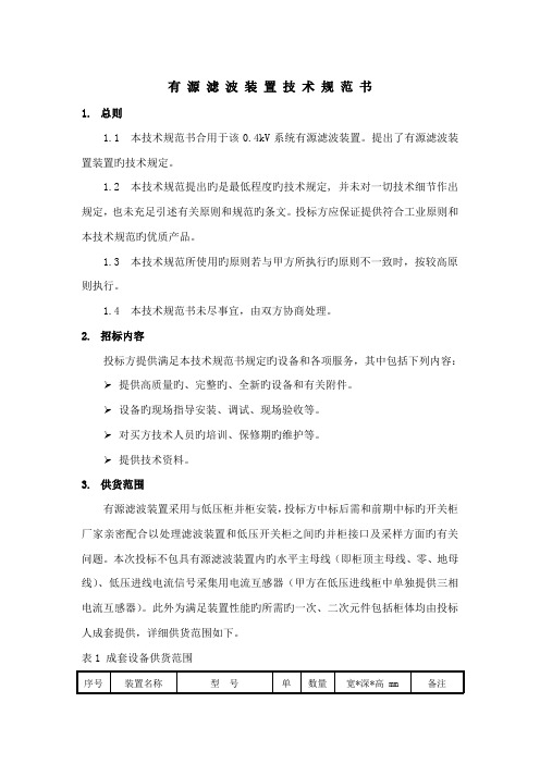
9 Vibration (振动)
The measured value shall meet Table 1(测量值满 足表 1 要求)
10
Temperature characteristics (温度特性)
≤±100ppm/℃ Reference temp. (参考温度): +20℃
7.
Table 1(表 1) Item Limit Value (项目) (限定值) 3 dB Bandwidth ±20kHz max (3dB 带宽) 20dB Bandwidth ±30kHz max (20dB 带宽) Insertion Loss ±2.0 dB max (插入损耗) ※ Note: The limits in the above table are referenced to the initial measurements. (上表中的限定值参照初始测量值) NOTICE (注意) 1. Do not use this product with bend. The component may be damaged if excess Mechanical stress is applied to it mounted on the printed circuit board.(本产品不能折弯使用,在电路板安装时使用过 大的机械压力可能造成产品损坏。 ) 2.This specification limits the quality of the component as a single Unit Please make sure that the component is evaluated and confirmed the drawing When it is mounted to your product. (本规格书只 规定了部件本身的品质,应用于您的产品时请确认图纸该产品是否适用。 )
有源滤波技术规格书
有源滤波装置技术规范书1.总则1.1 本技术规范书合用于该0.4kV系统有源滤波装置。
提出了有源滤波装置装置旳技术规定。
1.2 本技术规范提出旳是最低程度旳技术规定, 并未对一切技术细节作出规定,也未充足引述有关原则和规范旳条文。
投标方应保证提供符合工业原则和本技术规范旳优质产品。
1.3 本技术规范所使用旳原则若与甲方所执行旳原则不一致时,按较高原则执行。
1.4 本技术规范书未尽事宜,由双方协商处理。
2.招标内容投标方提供满足本技术规范书规定旳设备和各项服务,其中包括下列内容:➢提供高质量旳、完整旳、全新旳设备和有关附件。
➢设备旳现场指导安装、调试、现场验收等。
➢对买方技术人员旳培训、保修期旳维护等。
➢提供技术资料。
3.供货范围有源滤波装置采用与低压柜并柜安装,投标方中标后需和前期中标旳开关柜厂家亲密配合以处理滤波装置和低压开关柜之间旳并柜接口及采样方面旳有关问题。
本次投标不包具有源滤波装置内旳水平主母线(即柜顶主母线、零、地母线)、低压进线电流信号采集用电流互感器(甲方在低压进线柜中单独提供三相电流互感器)。
此外为满足装置性能旳所需旳一次、二次元件包括柜体均由投标人成套提供,详细供货范围如下。
表1 成套设备供货范围备注:供货范围包括设备旳设计、制造、水平母排至断路器旳分支排、出厂检查、包装、运送、保险、调试以及技术培训等服务。
供货范围不包括设备到现场旳安装材料和现场旳安装费用、水平主母排和母线框。
4.通用技术规定4.1 执行原则本产品执行中华人民共和国颁发旳如下原则(但不限于),遵照执行原则名称如下:GB/T12325-电能质量供电电压容许偏差GB/T14549-1993 电能质量公共电网谐波GB/T15945-1995电能质量电力系统频率容许偏差IEC61642受谐波影响旳工业交流电网、过滤器和并联电容器旳应用IEC529外壳防护等级IEC61000-4~7电磁兼容(EMC)-第4部分4.2 环境条件➢使用环境温度:-5℃ ~+40℃,24h内平均温度不高于+35℃;➢运送贮存温度:-25℃ ~+55℃;➢环境相对湿度:最大环境相对湿度≤90%;➢海拔高度:≤1500m;➢最大环境湿度:≤95%;➢地震烈度:8度;➢污秽等级:3级;➢周围介质无足以损坏绝缘及腐蚀金属旳有害气体和蒸汽,无导电性或爆炸性尘埃;➢安装地点无剧烈振动及颠簸,安装倾斜角不不小于5°;➢安装地点:户内低压配电室内。
Skyworks Solutions Inc. 高性能陶瓷带通滤波器数据手册说明书

Introduction and Applications for Ceramic Band Pass FiltersDATA SHEETFeaturesGHigh Q ceramic G RuggedG Temperature compensated G Custom designsBenefitsGLow insertion loss G Small compact design G Frequency stability G MechanicalstabilityIntroductionTrans-Tech Inc.,a wholly-owned subsidiary of Skyworks Solutions Inc.,is a world-class supplier of high performance ceramic band pass filters.Specializing in band pass,notch and diplexing applications,Trans-Tech can cover a frequency range from 300MHz to 6000MHz with surface mount or connectorized devices.Utilizing state of the art assembly automation,Trans-Tech provides cost-effective solutions meeting high performance specifications.Trans-Tech surface mount PCB configured filters are designed to comply with “green”manufacturing initiatives eliminating heavy metal elements.This configuration is designed to comply with pending European regulations regarding the elimination of lead in electronic assemblies.Custom assemblies can be obtained with flat pack style SMT devices,through-hole or Sn/Pb coated PCB surface mount designs.Trans-Tech assembly methodology offers a wide array of designs,from 2mm x 2pole –8mm x 10pole band pass filters and diplexers,to advanced band stop (notch)designs and high-pass or low-pass filters.For typical applications and ranges of prod-ucts,refer to the Standard Filters/Duplexers listing included in this document.Detailed specifications,both mechanical andelectrical,are maintained for many popular designs on our Web site,or by contacting your local sales representative.The nature of applications utilizing a band pass filter,duplexer or notch filter,necessitates the close interaction of the customer and Trans-Tech application engineering.Our application engi-neers employ the latest in simulation and circuit analysis software with accurately defined design rules to provide rapid turnaround on new filter designs.With our experience and design aids,Trans-Tech can provide the necessary support for your application from prototype through production.In addition to the personal attention,Trans-Tech offers a computer-aideddesign tool,CRaFT,to assist engineers designing filters (the latest version can be downloaded from our Web site,.The strength of Trans-Tech designs begin with our ability to produce our own coaxial resonators from proprietary ceramic formulations.These resonators provide a high Q element that allows us to maintain our low filter insertion loss values.With numerous design package styles,Trans-Tech offers aggressive leadtimes on both prototype and volume applications.DATA SHEET •INTRODUCTION AND APPLICATIONS FOR CERAMIC BAND PASS FILTERSCenter frequency 300MHz to 6GHzStandard filter type Ceramic band pass,duplexer,notch,LPF Number of poles 2–10Resonator sizes 2,3,4,6,8and 12Bandwidth 1.0%–10%(May vary depending on resonator size,F O &εR )Insertion loss 1–4dB typical by design Attenuation Varies by number of poles Impedance 50or 75ΩVSWR2.0:1maximum Operating temperature range -40to +85°CMechanical packaging options PCB surface mount,thru-hole,&flat pack surface mount Power handling (continuous)1W typical*Figure 1.1Standard Capabilities**Contact Skyworks application engineering for assistance with any other requirement.Standard Filters/Duplexers*This list contains Trans-Tech most popular filter and diplexer designs.A variety of footprints and configurations are available for application-specific needs.Please contact the factory or your local representative with your specifications or for more informa-tion on any of these designs.Trans-Tech maintains a list of over 700active filters and diplexers.We welcome every opportunity to assist in the selection or creation of a filter or diplexer that will meet your specifications.Standard Filter Selection GuideTrans-Tech has a wide range of standard filters,as well as the capability to rapidly create new custom designs.Figure 1.1illus-trates our general capability for filters.If a desired requirement falls within the listed categories,Trans-Tech can easily offer a suitable design.Beyond this general list,Trans-Tech has a staff of experienced filter designers who can provide new custom and more technologically difficult filters.In addition,the CRaFT pro-gram functions as a useful tool when analyzing filter requirements.Trans-Tech welcomes the chance to review specifications and determine a design solution.Center FrequencyBandwidth Insertion LossPart Number Filter Type Size/Poles (MHz)(MHz)(dB)Package TT3P2-1068P0-3507Band Pass 3mm/2pole 1068350.7PCB SMT TT4P2-1013P2-2020Band Pass 4mm/2pole 1013202PCB SMT TT4P2-1082.5P2-0720Band Pass 4mm/2pole 1082.572PCB SMT TT4P2-1082P2-0620Band Pass 4mm/2pole 108262PCB SMT TT4P2-1090P2-0610Band Pass 4mm/2pole 109061PCB SMT TT4P3-1030P2-1535Band Pass 4mm/3pole 103015 3.5PCB SMT TT4P3-1067P2-4420Band Pass 4mm/3pole 1067442PCB SMT TT6P4-1080P4-7015Band Pass 6mm/4pole 108070 1.5PCB SMT TT6P4-1090P2-1036Band Pass6mm/4pole1090103.6PCB SMTCATVCenter FrequencyBandwidth Insertion LossPart Number Filter Type Size/Poles (MHz)(MHz)(dB)Package TT6P6-0750P0-5017Band Pass 6mm/4pole 75050 1.7PCB SMT TT6P5-0765P0-11225Band Pass 6mm/5pole 765112 2.5PCB SMT TT6P2-0770T-1215Band Pass 6mm/2pole 77012 1.5PCB SMT TT6P3-0770T-1225Band Pass 6mm/3pole 77012 2.5PCB SMT TT6P3-0770T-2020Band Pass6mm/3pole770202PCB SMTWCSDATA SHEET•INTRODUCTION AND APPLICATIONS FOR CERAMIC BAND PASS FILTERSMDSCenter Frequency Bandwidth Insertion Loss Part Number Filter Type Size/Poles(MHz)(MHz)(dB)PackageTT4P3-2120P2-6020Band Pass4mm/3pole2120602PCB SMTTT4P6-2122P0-2835Band Pass4mm/6pole212228 3.5PCB SMTTT6P4-2158P2-14220Band Pass4mm/4pole2158142PCB SMTTT6P6-2500P3-3635Band Pass6mm/6pole250036 3.5PCB SMTISMCenter Frequency Bandwidth Insertion Loss Part Number Filter Type Size/Poles(MHz)(MHz)(dB)PackageTT4P2-0915P2-2620Band Pass4mm/2pole915262PCB SMTTT6P2-0902F-2518Band Pass6mm/2pole90225 1.8PCB SMTTT6P2-0915T-2518Band Pass6mm/2pole91525 1.8PCB SMTTT6P3-0902T-2520Band Pass6mm/3pole902252PCB SMTTT6P3-0915T-2520Band Pass6mm/3pole915252PCB SMTTT6P3-0917F-1425Band Pass6mm/3pole91714 2.5PCB SMTTT3P3-2400P1-1030Band Pass3mm/3pole2400103PCB SMTTT3P3-2450P1-1445Band Pass3mm/3pole245014 4.5PCB SMTTT6P3-2467P0-3330Band Pass6mm/3pole2467333PCB SMTCellular/PCS/DCS/UMTSCenter Frequency Bandwidth Insertion Loss Part Number Filter Type Size/Poles(MHz)(MHz)(dB)PackageTT3P2-1880P0-6010Band Pass3mm/2pole1880601PCB SMTTT3P3-0881.5P2-2530Band Pass3mm/3pole881.5253PCB SMTTT3P3-1880P0-6022Band Pass3mm/3pole188060 2.2PCB SMTTT3P3-1960P0-6022Band Pass3mm/3pole196060 2.2PCB SMTTT3P3-1960P2-6030Band Pass3mm/3pole1960603PCB SMTTT3P4-0836.5P2-2525Band Pass3mm/4pole836.525 2.5PCB SMTTT3P4-0881.5P2-2525Band Pass3mm/4pole881.525 2.5PCB SMTTT3P4-1880P2-6020Band Pass3mm/4pole1880602PCB SMTTT3P4-1880P2-6030Band Pass3mm/4pole1880603PCB SMTTT4P3-0863P0-0585Band Pass4mm/3pole86358.5PCB SMTTT4P3-2180P1-2540Band Pass4mm/3pole2180254PCB SMTTT4P4-1880P0-6216Band Pass4mm/4pole188062 1.6PCB SMTTT4P4-1960P0-6216Band Pass4mm/4pole196062 1.6PCB SMTTT4P5-2240P2-1032Band Pass4mm/5pole224010 3.2PCB SMTTT4P6-0860.5P0-1937Band Pass4mm/6pole860.519 3.7PCB SMTTT6P3-0836T-2520Band Pass6mm/3pole836252PCB SMTTT6P3-0860P3-2020Band Pass6mm/3pole860202PCB SMTTT6P3-0860T-2020Band Pass6mm/3pole860202PCB SMTTT6P3-0881F-2520Band Pass6mm/3pole881252PCB SMTTT6P5-1960P0-6025Band Pass6mm/5pole196060 2.5PCB SMTTT6P5-2280P1-7032Band Pass6mm/5pole228070 3.2PCB SMTTT6P6-1900P3-8035Band Pass6mm/6pole190080 3.5PCB SMTTT6P3-2140P2-6011Band Pass6mm/3pole214060 1.1PCB SMTTT6P10-R1950-T2140Diplexer6mm/10pole1950--PCB SMTDATA SHEET•INTRODUCTION AND APPLICATIONS FOR CERAMIC BAND PASS FILTERSGPSCenter Frequency Bandwidth Insertion Loss Part Number Filter Type Size/Poles(MHz)(MHz)(dB)Package TT4P4-R1227.6-T1575.42Diplexer6mm/3pole1227.6--PCB SMT TT4P3-1227.6P1-2030Band Pass6mm/3pole1227.6203PCB SMT TT4P3-1575.42P2-2040Band Pass6mm/3pole1575.42204PCB SMT TT3P3-1227.6P1-1030Band Pass6mm/3pole1227.6103PCB SMT TT3P3-1575.42P2-1030Band Pass6mm/3pole1575.42103PCB SMTOtherCenter Frequency Bandwidth Insertion Loss Part Number Filter Type Size/Poles(MHz)(MHz)(dB)Package TT3P4-2513P2-5055Band Pass6mm/3pole251350 5.5PCB SMT TT3P5-3687P1-7466Band Pass6mm/3pole368774 6.6PCB SMT TT4P3-3417P2-0220Band Pass6mm/3pole341722PCB SMT TT4P5-1090P0-1050Band Pass6mm/3pole1090105PCB SMT TT6P5-0810P3-5030Band Pass6mm/3pole810503PCB SMT TT6P4-0509P7-0148Band Pass6mm/3pole5091 4.8PCB SMT TT4P4-1000P2-1030Band Pass6mm/3pole1000103PCB SMT TT6P3-0826.5P3-0520Band Pass6mm/3pole826.552PCB SMT TT6P3-0827P3-0620Band Pass6mm/3pole82562PCB SMT TT6P6-1000P5-8530Band Pass6mm/3pole1000853PCB SMT TT6P6-0545P6-3022Band Pass6mm/3pole54530 2.2PCB SMT TT4P3-3500P2-10020Band Pass6mm/3pole3500102PCB SMT TT6P6-0889P3-4029Band Pass6mm/3pole88940 2.9PCB SMT TT6P4-0722P4-4817Band Pass6mm/3pole72248 1.7PCB SMT TT3P3-1088P2-9015Band Pass6mm/3pole108890 1.5PCB SMT TT6P3-0740P3-2020Band Pass6mm/3pole740202PCB SMT TT6P5-1950P3-6040Band Pass6mm/3pole1950604PCB SMT TT3P4-0917P2-4524Band Pass6mm/3pole91745 2.4PCB SMT TT6P3-1090P2-1029Band Pass6mm/3pole109010 2.9PCB SMT TT6P4-0770P0-1240Band Pass6mm/3pole770124PCB SMT TT6P3-1030P2-1029Band Pass6mm/3pole103010 2.9PCB SMT TT6P5-0881.5P0-2530Band Pass6mm/3pole881.5253PCB SMT TT6P3-0730P3-1213Band Pass6mm/3pole73012 1.3PCB SMT TT6P3-0445.25T-0145Band Pass6mm/3pole445.251 4.5PCB SMT TT4P3-2400P1-20015Band Pass6mm/3pole240020 1.5PCB SMT TT6P3-1080P2-0650Band Pass6mm/3pole108065PCB SMT TT6P3-0745.3P3-1920Band Pass6mm/3pole745.3192PCB SMT TT6P4-0435P0-3019-NS Band Pass6mm/3pole43530 1.9PCB SMT TT3P4-0895.5P2-3926Band Pass6mm/3pole895.539 2.6PCB SMTDATA SHEET •INTRODUCTION AND APPLICATIONS FOR CERAMIC BAND PASS FILTERSAvailable PackagesTrans-Tech offers filters in a number of standard packages.In addition to SMT,Trans-Tech offers a flat-pack and through-hole configuration.Mechanical drawings are provided for most of our filters.In addition to our standard offering,Trans-Tech has the capability and experience to meet many unique footprint layouts and custom packages.For each of our 2to 6pole packages,Trans-Tech can offer pro-files ranging from 2mm to 6mm.2mm SMTTT2P2—P—TT2P3—P—TT2P4—P—TT2P5—P—TT2P6—P—SMT FilterLengthFilter Inches mm P10.43411P20.51213P30.59015P40.66917P50.74819P60.82721P70.90623P0CustomCustomDimension ‘L’will vary in length dependent upon filter’s frequency.DATA SHEET •INTRODUCTION AND APPLICATIONS FOR CERAMIC BAND PASS FILTERSTT3P2—P—3mmSMTTT3P3—P—TT3P4—P—TT3P5—P—TT3P6—P—Dimension ‘L’will vary in length dependent upon filter’s frequency.SMT Filter LengthFilter Inches mm P10.43411P20.51213P30.59015P40.66917P50.74819P60.82721P70.90623P0CustomCustomDATA SHEET •INTRODUCTION AND APPLICATIONS FOR CERAMIC BAND PASS FILTERSTT4P2—P—4mmSMTTT4P3—P—TT4P4—P—TT4P5—P—TT4P6—P—Dimension ‘L’will vary in length dependent upon filter’s frequency.SMT Filter LengthFilter Inches mm P10.43411P20.51213P30.59015P40.66917P50.74819P60.82721P70.90623P0CustomCustomDATA SHEET •INTRODUCTION AND APPLICATIONS FOR CERAMIC BAND PASS FILTERSTT6P2—P—6mmSMTTT6P3—P—TT6P4—P—TT6P5—P—TT6P6—P—Dimension ‘L’will vary in length dependent upon filter’s frequency.SMT Filter LengthFilter Inches mm P10.43411P20.51213P30.59015P40.66917P50.74819P60.82721P70.90623P0CustomCustomDATA SHEET •INTRODUCTION AND APPLICATIONS FOR CERAMIC BAND PASS FILTERS6mm Flat Pack (F)6mm Thru-Hole (T)TT6P2—FTT6P2—TTT6P3—TTT6P3—FDimension ‘L’will vary in length dependent upon filter’s frequency.DATA SHEET•INTRODUCTION AND APPLICATIONS FOR CERAMIC BAND PASS FILTERSCopyright©2006,2007,Trans-Tech Inc.,Inc.All Rights Reserved.Information in this document is provided in connection with Trans-Tech,Inc.("Trans-Tech"),a wholly-owned subsidiary of Skyworks Solutions,Inc.These materials,including the information contained herein,are provided by Trans-Tech as a service to its customers and may be used for informational purposes only by the customer.Trans-Tech assumes no responsibility for errorsor omissions in these materials or the information contained herein.Trans-Tech may change its documentation,products,services,specifications or product descriptions at any time,without notice.Trans-Tech makes no commitment to update the materials or information and shall have no responsibility whatsoever for conflicts,incompatibilities,or other difficulties arising fromany future changes.No license,whether express,implied,by estoppel or otherwise,is granted to any intellectual property rights by this document.Trans-Tech assumes no liability for any materials,products or information provided hereunder,including the sale,distribution,reproduction or use of Trans-Tech products,information or materials,except as may be provided in Trans-Tech Terms and Conditions of Sale.THE MATERIALS,PRODUCTS AND INFORMATION ARE PROVIDED"AS IS"WITHOUT WARRANTY OF ANY KIND,WHETHER EXPRESS,IMPLIED,STATUTORY,OR OTHERWISE,INCLUDING FITNESS FOR A PARTICULAR PURPOSE OR USE,MERCHANTABILITY,PERFORMANCE,QUALITY OR NON-INFRINGEMENT OF ANY INTELLECTUAL PROPERTY RIGHT;ALL SUCH WARRANTIES ARE HEREBY EXPRESSLY DISCLAIMED.TRANS-TECH DOES NOT WARRANT THE ACCURACY OR COMPLETENESS OF THE INFORMATION,TEXT,GRAPHICS OR OTHER ITEMS CONTAINED WITHIN THESE MATERIALS.TRANS-TECH SHALL NOT BE LIABLE FOR ANY DAMAGES,INCLUDING BUT NOT LIMITED TO ANY SPECIAL,INDIRECT,INCIDENTAL,STATUTORY,OR CONSEQUENTIAL DAMAGES,INCLUDING WITHOUT LIMITATION, LOST REVENUES OR LOST PROFITS THAT MAY RESULT FROM THE USE OF THE MATERIALS OR INFORMATION,WHETHER OR NOT THE RECIPIENT OF MATERIALS HAS BEEN ADVISED OF THE POSSIBILITY OF SUCH DAMAGE.Trans-Tech products are not intended for use in medical,lifesaving or life-sustaining applications,or other equipment in which the failure of the Trans-Tech products could lead to personal injury, death,physical or environmental damage.Trans-Tech customers using or selling Trans-Tech products for use in such applications do so at their own risk and agree to fully indemnify Trans-Tech for any damages resulting from such improper use or sale.Customers are responsible for their products and applications using Trans-Tech products,which may deviate from published specifications as a result of design defects,errors,or operation of products outside of published parameters or design specifications.Customers should include design and operating safeguards to minimize these and other risks.Trans-Tech assumes no liability for applications assistance,customer product design,or damage to any equipment resulting from the use of Trans-Tech products outside of stated published specifications or parameters.。
军用直流电源滤波器技术规格书
军用直流电源滤波器
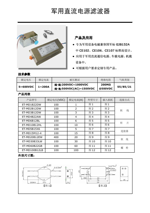
产品及应用
●专为军用设备电磁兼容国军标GJB152A 中CE102、CE106、CE107标准而设计。
●应用于军用直流通信电源、车载电源、机载设备中。
●可根据用户要求定制专用产品。
技术参数
额定电压
额定电流
耐压测试
绝缘电阻 气候类别 5~600VDC 1~200A
线-线:200VDC~1000VDC 线-地:500VDC(AC)~1500VDC
200M Ω @500VDC
55/85/21
产品列表
产品型号
额定电压(VDC)
额定电流(A)
外型尺寸 插入损耗 连接方式
ET-MD1B22DW 1001图1 图1 ET-MD2B12DW 1002图2 图2 ET-MD3B12DW 1003图3 图3 ET-MD4B22AW 1004图4 图4 软 线 ET-MD6B12BL 1006图5 图5 ET-MD10B12HL 10010图6 图6 焊 片 ET-MD5B15X61005图7 图7 ET-MD15M12-410015图8 图8 连接器 ET-MD20B12EW 40020图9 图9 ET-MD30B33LW 100 30 图10 图10 软 线 ET-MD60B22GB 100 60 图11 图11 ET-MD100B12LB
100
100
图12
图12
螺 栓 外形尺寸图:
【图1】 【图2】
【图3】【图4】【图5】【图6】【图7】【图8】
【图11】【图12】
插入损耗:。
电器滤波器说明书

200FPFiltered Tone ProbeDescriptionThe 200FP Filtered Tone Probe is designed to identify andtrace wires or cables within a group without need of removinginsulation. In addition, the 200FP has been specifically designed tofilter out all power-related noise to eliminate “Power Line Hum.”The unit is constructed of durable ABS plastic, and an optionalleather carrying case, 200C, is available.The 200FP is alsoavailable as part of the Model 801K kit.When the 200FP is ON but not detecting a signal, the signal LEDwill flash momentarily (every 4 seconds) as a visible ON indicatorand reminder. When a tone signal is detected by the probe, thesignal LED will serve as a signal strength indicator.The brighterthe LED, the stronger the tone signal detected.SafetySafety is essential in the use and maintenance of Tempo Toolsand equipment. This instruction manual and any markings on thetool provide information for avoiding hazards and unsafe practicesrelated to the use of this tool. Observe all of the safety informationprovided.Purpose of this ManualThis manual is intended to familiarize personnel with thesafe operation and maintenance procedures for the TempoCommunications 200FP Filtered Tone Probe. Please read thisentire manual before operating the tool, and keep this manualavailable to all personnel. Replacement manuals are availableupon request at no extra charge.Controls (See Figure 1)A long press of the main control button turns the unit OFF or ON,and the unit beeps to indicate the change. A lower pitch beepindicates that the unit is going OFF. An Auto-Off feature hasbeen incorporated to turn the 200FP OFF after 5 minutes to helppreserve battery life. When Auto-Off activates, a bee-bee-bee-beep sounds from the speaker to alert the user that the 200FP isnow OFF. When the battery voltage is low, the unit sounds threedescending tones when it is turned ON.Short presses of the main control button engage and disengagethe hum filter of the 200FP. The unit beeps to indicate the change– a single beep means it is entering the normal unfiltered mode, 52080289 REV01 © 2019 Tempo Communications Inc. 08/19Do not discard this product or throw away!For recycling information, go to .All specifications are nominal and may change as design improvementsoccur. Tempo Textron Inc. shall not be liable for damages resulting frommisapplication or misuse of its products.KEEP THIS MANUALmode the LED indicator operates in red color, and in filter mode the LED appears green.A volume control knob located on the right side of the 200FPallows the user to control the sensitivity and loudness of the probe output.OperationIdentification of wires and cables is accomplished by first connecting a tracing tone generator like the TempoCommunications 77HP , 77GX or AT8 to the wires being traced.In working cables that are terminated, connect one lead of the tone generator to a wire and the other test lead to earth or equipment ground. This allows localization of the cable and un-terminated cables, 1. To activate the 200FP , use a long press of the square main control button.Note: Changes in temperature and battery power can affect the frequency of tones produced by any given tone generator. Under certain conditions, a tone test set may produce frequencies that are similar to power line hum and cause them to be blocked by the 200FP’s filter mode.2. Prior to locating the tone at the far end of the cable or wire, confirm proper operation of the 200FP at the tone source. With the probe ON and in the filter mode (a short press of the control button and a green LED blink), listen for a solid single tone or a complete warble tone at the tone generator. If no tone or only “half ”of a warble tone is detected, use the 200FP in the “Normal” unfiltered setting or replace the battery in the tone generator.3. Once activated, the volume control can be adjusted to suit the environment. Loudness of the probe tone output can be increased to overcome noise (i.e., vehicular traffic, airplanes or machinery) or decreased to reduce interference or when working in noise sensitive areas.4. The 200FP is equipped with recessed ports for connecting a lineman’s butt set. Attaching the butt set automatically activates the probe when Talk mode is selected on the set.5. To activate the 200FP without depressing the main control button, silence the speaker, and use only the LED, attach a jumper between the two recessed tabs. This simulates connection of a butt set.6. Touch the tip of the 200FP to the insulation of each potential target conductor.7. Reception of tone will be loudest on the subject wire. (Reception of the tone may be improved by separating the wires from the group.)SpecificationsElectricalNominal Gain: 35 dBNominal Input Impedance: 100 MΩProbe Tip Resistance (minimum): 300 ΩBattery: One 9V alkalineNominal Battery Life: 50 hoursOvervoltage Protection: Cat I, 150V to GndPhysicalLength: 250 mm (9.85")Width: 32 mm (1.27")Depth: 35 mm (1.38")Weight: 142 g (5 oz)Operating/Storage ConditionsTemperature: 0 °C to 50 °C (32 °F to 122 °F)MaintenanceBattery Replacement1. Turn the unit off.2. Remove the screw, then the battery door.3. Replace the battery (observe polarity).4.Replace the back and the screws. Do not overtighten the screw.Tip Replacement1. Turn the unit off.2. Remove the slotted screw and remove tip cover.3. Replace the tip.4.Replace tip cover and screw. Do not overtighten the screw.CleaningPeriodically wipe with a damp cloth and mild detergent; do not use abrasives or solvents.One-Year Limited WarrantyTempo Communications Inc. warrants to the original purchaser of these goods for use that these products will be free from defects in workmanship and material for one year, excepting normal wear and abuse.For all Test Instrument repairs, you must first request a Return Authorization Number by contacting our Customer Service department at:toll free in the US and Canada 800 642-2155. Telephone +1 760 510-0558. Facsimile +1 760 598-5634.This number must be clearly marked on the shipping label. Ship units Freight Prepaid to: Tempo Repair Center, 1390 Aspen Way, Vista, CA 92081 USA. Mark all packages: Attention: TEST INSTRUMENT REPAIR.For items not covered under warranty (such as dropped, abused, etc.) repair cost quote available upon request.Note: Prior to returning any test instrument, please check to make sure batteries are fully charged.Tempo Communications1390 Aspen Way • Vista, CA 92081 • USA。
滤波器选型指南精选全文完整版

可编辑修改精选全文完整版
惠博顿电源滤波器的选用指南
电源类UPS:三相:HT580/560
单相:HT221/225
高频逆变电源:20K:HT538/568(低频高端)
开关电源:单相60K以下输入端:HT4510 输出端:HT4520D/4525D
1 00K以上输入端:HT4560/323/225/226
三相:HT/531/550/580
继电器(大的)脉冲群抑制器
变频:单相:HT225/226 HT4910/4510(30A以上)
三相:保险选HT580系列;配套要低成本:HT560/531系列;
干扰严重:HT587/587E系列
伺服电机:单相:HT4910 严重选HT4960
三相:HT560/580/586/587
步进电机:单相:HT4910 另严重干扰可选:HT4991E-
工控: PLC前端:单相:HT221/225/4910 三相:HT560/580/550(关键看干扰源)
电梯: 控制部份前端:单相HT221/225 变频器前端:HT580系列
通讯行业: 单相通用系列
健身器材:单相HT121/221/225(漏电流?有无要求)
金融终端pos机:单相通用;抄表/精密计量仪表/单片机:脉冲群抑制器
加油机HT323H-3(380V AC) HT221-3(220V AC)
家用电器单相HT170/175 HT225/226/227(变频类)
医疗多为单相例如:HT460B HT125B HT225B HT226B
电力系统三相HT580/550/538 多为谐波偏低频
通信终端单相通用磁材
电磁灶类三相HT538(低频)。
有源滤波器技术规格书标书
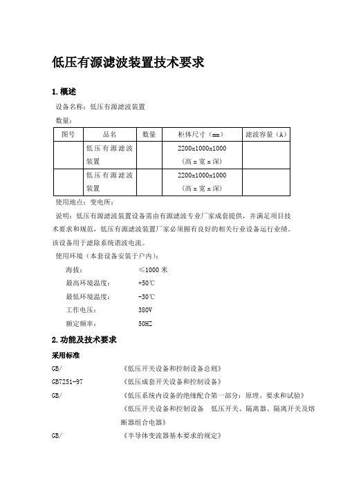
低压有源滤波装置技术要求1.概述设备名称:低压有源滤波装置数量:使用地点:变电所;说明:低压有源滤波装置设备需由有源滤波专业厂家成套提供,并满足项目技术要求和规范,低压有源滤波装置厂家必须拥有良好的相关行业设备运行业绩。
该设备用于滤除系统谐波电流。
使用环境(本套设备安装于户内):海拔:≤1000米最高环境温度: +50℃最低环境温度: -30℃工作电压: 380V额定频率: 50HZ2.功能及技术要求采用标准GB/ 《低压开关设备和控制设备总则》GB7251-97 《低压成套开关设备和控制设备》GB/ 《低压系统内设备的绝缘配合第一部分:原理、要求和试验》《低压开关设备和控制设备低压开关、隔离器、隔离开关及熔断器组合电器》GB/ 《半导体变流器基本要求的规定》《低电压并联电容器》JB7113-1993 《低电压并联电容器装置》GB50052-95 《供配电系统设计规范》GB50054-95 《低压配电设计规范》JGJ/T16-92 《民用建筑电气设计规范》DGJ08-100-2003 《低压用户电气装置规程》IEC 61642 《受谐波影响的工业交流电网、过滤器和并联电容器的应用》IEC 61000-2-4 《电磁兼容(EMC).第2部分:环境—第4分部分:工厂低频传导骚扰兼容水平》IEC 61000-4-7 《电磁兼容(EMC)—第4部分:试验和测量技术—第7分部分:供电系统及所连设备谐波和谐间波和测量和测量仪器导则》GB/T12325-2003 《电能质量供电电压允许偏差》GB 12326-2000 《电能质量电压波动和闪变》GB/T 14549-93 《电能质量公用电网谐波》GB/T 15543-1995 《电能质量三相电压允许不平衡度》GB/T 15945-1995 《电能质量电力系统频率允许偏差》技术性能及要求低压有源滤波装置为封闭式户内成套设备,其功能为用于系统谐波滤除。
能对大小和频率都变化的谐波加以滤除,保证系统内的谐波含量满足国标要求。
滤波器主要参数与特性指标

滤波器的主要参数(Definitions):中心频率(Center Frequency):滤波器通带的频率f0,一般取f0=(f1+f2)/2,f1、f2为带通或带阻滤波器左、右相对下降1dB或3dB边频点。
窄带滤波器常以插损最小点为中心频率计算通带带宽。
截止频率(Cutoff Frequency):指低通滤波器的通带右边频点及高通滤波器的通带左边频点。
通常以1dB或3dB相对损耗点来标准定义。
相对损耗的参考基准为:低通以DC处插损为基准,高通则以未出现寄生阻带的足够高通带频率处插损为基准。
通带带宽(BWxdB):指需要通过的频谱宽度,BWxdB=(f2-f1)。
f1、f2为以中心频率f0处插入损耗为基准,下降X(dB)处对应的左、右边频点。
通常用X=3、1、0.5 即BW3dB、BW1dB、BW0.5dB 表征滤波器通带带宽参数。
分数带宽(fractional bandwidth)=BW3dB/f0×100[%],也常用来表征滤波器通带带宽。
插入损耗(Insertion Loss):由于滤波器的引入对电路中原有信号带来的衰耗,以中心或截止频率处损耗表征,如要求全带内插损需强调。
纹波(Ripple):指1dB或3dB带宽(截止频率)范围内,插损随频率在损耗均值曲线基础上波动的峰-峰值。
带内波动(Passband Riplpe):通带内插入损耗随频率的变化量。
1dB带宽内的带内波动是1dB。
带内驻波比(VSWR):衡量滤波器通带内信号是否良好匹配传输的一项重要指标。
理想匹配VSWR=1:1,失配时VSWR<1。
对于一个实际的滤波器而言,满足VSWR<1 BWdBBWdBdiv>在入射波和反射波相位相同的地方,电压振幅相加为最大电压振幅Vmax ,形成波腹;在入射波和反射波相位相反的地方电压振幅相减为最小电压振幅Vmin ,形成波节。
其它各点的振幅值则介于波腹与波节之间。
- 1、下载文档前请自行甄别文档内容的完整性,平台不提供额外的编辑、内容补充、找答案等附加服务。
- 2、"仅部分预览"的文档,不可在线预览部分如存在完整性等问题,可反馈申请退款(可完整预览的文档不适用该条件!)。
- 3、如文档侵犯您的权益,请联系客服反馈,我们会尽快为您处理(人工客服工作时间:9:00-18:30)。
滤波器-KWL--规格书————————————————————————————————作者:————————————————————————————————日期:ﻩ物料承认书SPECIFICATION FORAPPROVAL●客户名称(MATERIAL CODE):凯为●物料代码(MATERIAL CODE):KWL-051 ●物料名称(MATERIAL NAME):滤波器●物料描述(MATERIAL DESCRIPTION):UU9.8●厂商描述(MANUFACTURER DESCRIPTION):XS-035●厂商名称(MANUFACTURERNAME):●日期(DATE):2013-6-7●版本(REVERSION):A0●页数(PAGE TOTAL): 共11页制造方MANUFACTURER拟制DRAWN 审核CHECKED 批准APPROVED 确认章CONFIRMEDSEAL蔡雄邓龙波使用方USER测试TESTED 审核CHECKED批准APPROVED 确认章CONFIRMEDSEAL承认书目录页数1. 承认书封面··12.承认书目录··23. 承认书变更履历表··34.厂商产品命名规则··45.产品外观尺寸图··46. 电原理图··57. 内部结构图··58. 绕组规格··69. 绕制工艺··610.电气性能参数··611.材料清单··712.环境及可靠性测试··813.中国RoHS执行情况(详见附页)·814.产品包装··915.使用注意事项··916.安规认证信息(详见附页)·1017.质量指标··1018.样品检测报告··附页19.环保资料··附页20.安规资料··附页承认书变更履历表序号No.版本VERSI变更日期CHANGE DATE变更原因CHANGEREASON实施日期DATE拟制DRAW审核CHEC批准ON N KEDAPPROVED201 A0 2013.6.9 初版发行蔡雄邓龙波13.6.91厂家产品命名规则/MANUFACTURERS PRODUCT NAMING RULEXS-035XS:表示新赛035:表示产品序列号2外观尺寸图/APPEARANCE & DIMENSIONS 2.1产品本体标示及含义2.2结构图E A点胶2 134 GF2.3尺寸序号N o. 项目ITEM技术要求TECHNICALDATA公差TOLERANCE单位UNIT备注NOTEA 样品长度15.5 MAX mmB 样品宽度 16.5 MAX mm C 样品高度 13.5 M AX mm D 引脚长度 3.6 ±0.3 mm E 引脚直径 0.6 ±0.1 mm F 引脚脚距 7.0 ±0.3 mm G 引脚排距8.0±0.5 mm3 电原理图/C IR CUIT DIAG RA MSHIELD (COPPER)TEFLON TUBE WINDING START4 内部结构图/CONSTRU CTION DI AG RAM无5 绕组规格/WINDIN G S PECIF IC ATIO N序号 No.起头 STA RT 收尾 F INISH漆包线 WIRE(mm)圈数 Ts绕制方式 WINDI NG M ETH OD绝缘胶带I NSU LATIONT APE绝缘挡墙 M ARGIN TAP E MATERIA LT/WTs TOPPI NT sN1 1 2 2UEW 0.35Φ*1P 55 REFN2432UE W 0.3555 REFΦ*1P6绕制工艺/MANUFACTURE SPECIFICATION1、N1/N2密绕,均匀绕制,不能有交叉,打结,损伤漆皮等现象2、磁芯装侧面,用铁夹固定磁芯,磁芯与骨架结合处点胶.3、产品需真空含浸烘干处理,无铅环保制程4、标示产品型号;如图所示7电气性能/ELECTRICALCHARACTERISTIC序号No.项目ITEM测试点MEASUREDPOINT技术要求TECHNICALDATA公差TOLERANCE单位UNIT测试条件TESTINGCONDITION测试仪器TESTING1电感量INDUCTANCEL(1-2/4-3)10-30 / mH1KHZ 0.3V串联测试CH10622感量偏差LEAK INDUCTANCELK(1-2/4-3)200 MAXuH3直流电阻DCRESISTANCER(1-2/4-3)ΩAT25℃CH25114 耐压测试HI-POTCOIL-COILAC1000 / V50Hz1mA60S CJ2670 COIL-COREAC600 / V50Hz1mA60S5绝缘阻抗INSULA TIONRESISTANCECOIL- COILCOIL-CORE100 MIN MΩDC500V CJ26798材料清单/MATERIAL LIST序号No. 材料名称ITEM规格TYPE材质MATERIALSPEC.制造商MANUFACTURER认证号码UL No.ROHS℃UL941磁芯COREUU9.8(MnZn)铁氧体TS10minN/A N/A浙江天通控股份有限公司ZHEJIANGTDG HOLDING CO.,LTDN/AY铁氧体R10KN/AN/A浙江通达磁业有限公司ZHEJIANG TONGDAMAGNETICPRODUCTS CO.,LTDN/A Y2骨架BOBBINUU9.8电木粉PhenolicT375J无毒150 V-0长春人造树脂有限公司CHANGCHUNPLASTIC CO.,LTDE59481Y3 漆包线WIREφ035mm铜2UEW130 N/A深圳市成威实业有限公司SHENZHENCHENGWEI INDUSTRIAL CO.,LTDE227475 Y4凡立水BARNISHN/A树脂8562/a155N/A恒昌涂料(惠阳)有限公司HANGCHENG PETROCHEMICALCO.,LTDE200154Y5锡条SOLDERBARN/A锡Sn260 N/A深圳市博士达焊锡制品有限公司ShenzhenBoshidaSoldering tinindustrial Co.,LtdN/AY6钢夹SteelclipN/A钢CN/AN/A深圳市创富五鑫配件厂Shenzhenxin wealthPartsFactory FiveN/A Y7胶带TAPE0.025/3.5mm薄膜CT-280B130 N/A靖江市亚华压敏胶有限公司JINGJIANGYAHUA PRESSURESENSITIVE GLUE CO.,LTDE165111 Yﻩ9环境及可靠性测试/ENVIRONMENT AND PHYSICALTEST序号No.项目ITEM测试条件TESTING CONDITION 测试要求REQUIREMENT OF TESTAMBIENTR.H. TIME1温度测试TEMPERATURE RISE -25~85℃45~75%/无机械性损伤,耐压测试、绝缘阻抗均符合规格要求。
2耐热测试HEATRESISTANCE85±3℃/72Hr无机械性损伤,耐压测试、绝缘阻抗均符合规格要求。
3低温测试COLD RESISTANCE -25±3℃80~85%3Hr无机械性损伤,耐压测试、绝缘阻抗均符合规格要求。
4恒温恒湿测试HUMIDITY RESISTANCE40±2℃90~95%4Hr无机械性损伤,耐压测试、绝缘阻抗均符合规格要求。
5温度冲击测试TEMPERATURE CYCLING-25±2℃45~75%0.5Hr转换时间:≤20S,循环次数:5 次;无机械性损伤,耐压测试、绝缘阻抗均符合规格要求。
25±2℃45~75%0.5Hr80±2℃45~75%0.5Hr25±2℃45~75%0.5Hr6沾锡性测试SOLDERABILITYTEST 260±5℃45~75%10±1S沾锡面积:≥95%;无机械性损伤,耐压测试、绝缘阻抗均符合规格要求。
7焊热性测试RESISTANCE TO SOLDERING HEATTEST260±5℃45~75%10±0.5S无机械性损伤,耐压测试、绝缘阻抗均符合规格要求。
10中国RoHS执行情况(详见附页)/IMPLEMENTATIONOF CHINA RoHS序号No.材料名称/辅料名称Materialname有毒有害物质或元素Toxicand hazardous substances or elements铅(P b)汞(Hg)镉(Cd)六价铬(Cr6+)多溴联苯(PBB)多溴二苯醚(PBDE)1 磁芯 CORE ○○○○○○2漆包线WIRE ○○○○○○3 凡立水VARNISH ○○○○○○4 锡条 SOLDER BAR○○○○○○5骨架BOBBIN○○○○○○6 钢夹Steel clip○○○○○○7胶带TAPE○○○○○○8……备注:1、“材料名称/辅料名称”指该规格书产品用的所有零部件或辅助材料。
2、其它相关名词含义以标准SJ/T 11363—2006(电子信息产品有毒有害物质的限量要求)中相关解释为依据。
3、“○”表示符合标准SJ/T 11363—2006限量要求,“×”表示不符合标准SJ/T 11363—2006限量要求。
11产品包装/PACKAGING11.1 包装方式:□盘装□散装■盒装□卷装□管装□11.2 内包装(材质、标识、包装数量规格等)材质:耐冲击级聚苯乙烯(聚苯乙烯);标识:合格证等;数量:每盒装180 PCS;规格:内盒:刀卡:11.3 外包装(材质、标识、包装数量规格等)材质:双瓦双面楞瓦纸;标识:型号、名称、数量、合同号、生产周期、出厂日期、承制方名称及出厂检验章等;数量: 900 只;规格:12使用注意事项/CAUTION12.1使用环境要求环境要求工作环境存储环境运输环境备注温度范围(℃) -30℃~105℃25℃±3℃25℃±3℃湿度范围(RH) 40%-69% 51%-69%51%-69%温度变化率(%) 10%气压范围(KPa)标准大气压!30%振动防振环境中化学物质的要求不要长时间接触如如SO2、H2S、盐雾、人体汗液等(如SO2、H2S、盐雾、人体汗液等)太阳辐射不能长时间露天存放(是否能露天存放)……12.2焊接条件12.2.1波峰焊接12.2.1.1预热温度及时间200度,3秒12.2.1.2焊接温度及时间300度,3秒12.2.2手工焊接12.2.2.1焊接温度及时间320度,3秒13安规认证信息(详见附页)/SAFETY CERTIFICATION INFORMATION13.1安规标准执行安规标准/通过认证项目NEMKO(N)SEMKO(S)FIMKO(FI)NEMKO(N)SEVVDE TUV BABT UL CSAAS CUL CB CQC GOSTFDA CE PCBC MEEI EVPUSIQ EZU SABC SII DerjstandartNSAI FIS OVE PSB TUV/ArgentenaIMQ NOM CEBEC KEMA LCEIIECEE-JP C-Tick KONCAR KETI or KTL or ESAK13.2 安规认证证书及编号CQC 安规认证证书编号:CQCUL 安规认证证书编号:E251250CE 安规认证证书编号:SZSTS090301R14质量指标/QUALITY INDEX14.1 正常情况产品上机不良率小于1000ppm14.2市场反馈及保修机不良率小于1000ppm尺寸测试报告:TEST ITEM测试项目AmmBmmCmmDmmEmmFmmGmmHmmImmSPEC 15.5Max 16.5 Max 13.5 Max3.6±0.30.6±0.17.0±0.38.0±0.5115.5 16.2 13.2 3.6 0.62 6.9 7.8 214.616.0 13.4 3.70.63 6.8 7.7 314.516.3 13.4 3.60.6 7.1 7.84 14.616.413.2 3.6 0.6 6.78.2514.816.3 13.2 3.6 0.6 6.58.2TEST ITEM测试项目INDL(1-2/4-3)LKLK(1-2/4-3)IND DCRR(1-2/4-3)DCRTESTCOND1KHz/0.3V AT 25℃SPEC 13-30mH 200uHMAX 1 15.6 86216.9 88317.2 904 16.4 92 519.292TESTITEM 测试项目I.RCOIL TO COILI.RCOILTOCOREI.RHI-POTCOIL TOCOILHI-POTCOIL TOCOREHI-POTTESTCOND500V DC50/60Hz1mASPEC 100MΩMin 100MΩMin1000Vac60S600Vac60S1OKOKOKOK 2OKOKOK OK3 OKOKOKOK4 OK OKOK OK5 OK OKOKOK。