船舶毕业设计翻译文献
船舶专业英语课文翻译精编版

船舶专业英语课文翻译公司标准化编码 [QQX96QT-XQQB89Q8-NQQJ6Q8-MQM9N]Chapter 1 Ship Design(船舶设计)Lesson 2 Ships Categorized(船舶分类)2.1 Introduction(介绍)The forms a ship can take are innumerable. 一艘船能采用的外形是不可胜数的A vessel might appear to be a sleek seagoing hotel carrying passengers along to some exotic destination; a floating fortress bristling with missile launchers; 。
or an elongated box transporting tanks of crude oil and topped with complex pipe connections. 一艘船可以看做是将乘客一直运送到外国目的地的优美的远航宾馆。
竖立有导弹发射架的水面堡垒及甲板上铺盖有复杂管系的加长罐装原油运输轮None of these descriptions of external appearance, however, does justice to the ship system as a whole and integrated unit所有这些外部特点的描述都不能说明船舶系统是一个总的集合体—self-sufficient,seaworthy, and adequately stable in its function as a secure habitat for crew and cargo. ——船员和货物的安全性功能:自给自足,适航,足够稳定。
This is the concept that the naval architect keeps in mind when designing the ship and that provides the basis for subsequent discussions, not only in this chapter but throughout the entire book.这是一个造船工程师设计船舶使必须记住的、能为以后讨论提供根据的观念,不仅涉及本章也贯穿全书。
船舶设计外文文献翻译

船舶设计外文文献翻译
船舶设计是一门工程学科,它涉及到船舶的结构设计、推进系统、船舶动力学和稳性等方面。
通过船舶设计,可以确保船舶具有良好的航行性能、结构强度和安全性。
船舶设计常常依赖于计算机辅助设计系统,这些系统可以帮助设计师在设计过程中进行模拟和优化。
船舶设计人员需要综合考虑船舶的使用需求、航行条件、载货量和船舶的造价等因素。
他们还需要进行性能预测和结构强度计算,以确保船舶设计满足相关的规范和标准。
现代船舶设计中,船舶外形设计是一个重要的环节。
船舶的外形设计直接影响到其航行性能和稳定性。
通过优化船体外形,可以提高船舶的速度、降低燃油消耗,并减少船舶在恶劣天气和大浪影响下的波浪干扰和倾覆风险。
除了推进系统,船舶的船体结构也是设计的一个重要部分。
船体结构设计需要考虑船舶的载荷分布、结构强度和疲劳寿命等因素。
船体结构的设计要符合相关的规范和标准,以确保船舶的安全性和稳定性。
总之,船舶设计是一门复杂的科学,它需要综合考虑船舶的各个方面和要求。
通过合理的船舶设计,可以确保船舶在各种航行条件下的安全性和性能。
船舶专业外文翻译--船舶设计优化

船舶专业外文翻译一船舶设计优化Ship Design OptimizationThis contribution is devoted to exploiting the analogy between a modern manufacturing plant and a heterogeneous parallel computer to construct a HPCN decision support tool for ship designers. The application is a HPCN one because of the scale of shipbuilding ・ a large container vessel is constructed by assembling about 1.5 million atomic components in a production hierarchy. The role of the decision support tool is to rapidly evaluate the manufacturing consequences of design changes. The implementation as a distributed multi-agent application running on top of PVM is described1 Analogies between Manufacturing and HPCNThere are a number of analogies between the manufacture of complex products such as ships, aircraft and cars and the execution of a parallel program. The manufacture of a ship is carried out according to a production plan which ensures that all the components come together at the right time at the right place.A parallel computer application should ensure that the appropriate data is available on the appropriate processor in a timely fashion.It is not surprising, therefore, that manufacturing is plagued by indeterminacy exactly as are parallel programs executing on multi-processor hardware. This has caused a number of researchers in production engineering to seek inspiration in other areas where managing complexity and unpredictability is important. A number of new paradigms^ such as Holonic Manufacturing and Fractal Factories have emerged [1,2] which contain Ideas rather reminiscent of those to be found inthe field of Multi- Agent Systems [3,4].Manufacturing tasks are analogous to operations carried out on data, within the context of planning, scheduling and control. Also, complex products are assembled at physically distributed workshops or production facilities^ so the components must be transported between them. This is analogous to communication of data between processors in a parallel computer, which thus also makes clear the analogy between workshops and processors.The remainder of this paper reports an attempt to exploit this analogy to build a parallel application for optimizing ship design with regard to manufacturing issues.2 Shipbuilding at Odense Steel ShipyardOdense Steel Shipyard is situated in the town of Munkebo on the island of Funen. It is recognized as being one of the most modern and highly automated in the world. Itspecializes in building VLCC's (supertankers) and very large container ships. The yard was the first in the world to build a double hulled supertanker and is currently building an order of 15 of the largest container ships ever built for the Maersk line. These container ships are about 340 metres long and can carry about 7000 containers at a top speed of 28 knots with a crew of 12.Odense Steel Shipyard is more like a ship factory than a traditional shipyard. The ship design is broken down into manufacturing modules which are assembled and processed in a number of workshops devoted to, for example, cutting, welding and surface treatment. At any one time, up to 3 identical ships are being built and a new ship is launched about every 100 days.The yard survives in the very competitive world of shipbuilding by extensive application of information technology and robots, so there are currently about 40 robots at the yard engaged in various production activities. The yard has a coininitment to research as well, so that there are about 10 industrial Ph・D・students working there, who are enrolled at various engineering schools in Denmark.3 Tomorrow's Manufacturing SystemsThe penetration of Information Technology into our lives will also have its effect in manufacturing Industry. For example, the Internet is expected to becomethe dominant trading medium for goods. This means that the customer can come Into direct digital contact with the manufacturer.The direct digital contact with customers will enable them to participate in the design process so that they get a product over which they have some influence. The element of unpredictability introduced by taking into account customer desires increases the need for flexibility in the manufacturing process, especially in the light of the tendency towards globalization of productioiLIntelligent robot systems, such as AMROSE, rely on the digital CAD model as the primary source of information about the work piece and the work cell [5,6].This information is used to construct task performing, collision avoiding trajectories for the robots, which because of the high precision of the shipbuilding process, can be corrected for small deviations of the actual world from the virtual one using ven r simple sensor systems. The trajectories are generated by numerically solving the constrained equations of motion for a model of the robot moving in an artificial force field designed to attract the tool centre to the goal and repell it from obstacles, such as the work piece and parts of itself. Finally, there are limits to what one can get a robot to do, so the actual manufacturing will be performed as a collaboration between human and mechatronic agents.Most industrial products, such as the windmill housing component shown in Fig. 1, are designed electronically in a variety of CAD systems.Fig> 1. Showing the CAD model for the housing of a windmilL The model, made using Bentley Microstation, includes both the work-piece and task-curve geometries.4 Today v s Manufacturing SystemsThe above scenario should be compared to today's realities enforced by traditional production engineering philosophy based on the ideas of mass production introduced about 100 years ago by Henry Ford. A typical production line has the same structure as a serial computer program, so that the whole process is driven by production requirements. This rigidity is reflected on the types of top-down planning and control systems used in manufacturing industry, which are badly suited to both complexity and unpredictability.In fact, the manufacturing environment has always been characterized by unpredictability. Today's manufacturing systems are based on idealized models where unpredictability is not taken into account but handled using complex and expensive logistics and buffering systems.Manufacturers are also becoming aware that one of the results of the top-down serial approach is an alienation of human workers. For example, some of the car manufacturers have experimented with having teams of human workers responsible for a particular car rather than performing repetitive operations in a production line. This model in fact better reflects the concurrency of the manufacturing process than the assembly line.5 A Decision Support Tool for Ship Design OptimizationLarge ships are, together with aircraft, some of the most complex things ever built A container ship consists of about 1.5 million atomic components which are assembled in a hierarchy of increasingly complex components. Thus any support tool for the manufacturing process can be expected to be a large HPCN application.Ships are designed with both functionality and ease of construction in mind, as well as issues such as economy, safety, insurance issues, maintenance and even decommissioning. Once a functional design is in place, a stepwise decomposition of the overall design into a hierarchy of manufacturing components is performed. The manufacturing process then starts with the individual basic building blocks such as steel plates and pipes. These building blocks are put together into ever more complex structures and finally assembled in the dock to form the flnished ship.Thus a very useful thing to know as soon as possible after design time are the manufacturing consequences of design decisions. This includes issues such as whether the intermediate structures can actually be built bv the availableproduction facilities, the implications on the use of material and whether or not the production can be efficiently scheduled [7].Fig.2. shows schematically how a redesign decision at a point in time during construction implies future costs, only some of which are known at the time. Thus a decision support tool is required to give better estimates of the implied costs as early as possible in the process.Simulation,both of the feasibility of the manufacturing tasks and the efficiency with which these tasks can be performed using the available equipment, is a very compute-intense application of simulation and optimization. In the next section, we describe how a decision support tool can be designed and implemented as a parallel application by modeling the main actors in the process as agents.Fig>2> Economic consequences of design decisions. A design decision implies a future commitment of economic resources which is only partially known at design time.6 Multi-Agent SystemsThe notion of a software agent, a sort of autonomous, dynamic generalization of an object (in the sense of Object Orientation) is probably unfamiliar to the typical HPCN reader in the area of scientific computation. An agent possesses its own beliefs, desires and intentions and is able to reason about and act oil its perceptionof other agents and the environment.A multi-agent system is a collection of agents which try to cooperate to solve some problem, typically in the areas of control and optimization. A good example is the process of learning to drive a car in traffic. Each driver is an autonomous agent which observes and reasons about the intentions of other drivers. Agents are in fact a very useful tool for modeling a wide range of dynamical processes in the real worlds such as the motion of protein molecules [8] or multi-link robots [9]. For other applications, see [4].One of the interesting properties of multi-agent systems is the way global behavior of the system emerges from the individual interactions of the agents [10]. The notion of emergence can be thought of as generalizing the concept of evolution in dynamical systems.Examples of agents present in the system are the assembly network generator agent which encapsulates knowledge about shipbuilding production methods for planning assembly sequences, the robot motion verification agent, which is a simulator capable of generating collision-free trajectories for robots carrying out their tasks, the quantity surveyor agent which possesses knowledge about various costs involved in the manufacturing process and the scheduling agent which designs a schedule for performing the manufacturing tasks using the production resources available.7 Parallel ImplementationThe decision support tool which implements all these agents is a piece of Object- Oriented software targeted at a multi-processor system, in this case, a network of Silicon Graphics workstations in the Design Department at Odense Steel Shipyard. Rather than hand-code all the communication between agents and meta-code for load balancing the parallel application, abstract interaction mechanisms were developed. These mechanisms are based on a task distribution agent being present on each processor. The society of task distribution agents is responsible for all aspects of communication and migration of tasks in the system.The overall agent system runs on top of PVM and achieves good speedup and load balancing. To give some idea of the size of the shipbuilding application^ it takes 7 hours to evaluate a single design on 25 SGI workstations.From:Applied Parallel Computing Large Scale Scientific and Industrial Problems LectureNotes in Computer Science, 1998, Volume1541/199& 476-482, DOI: 10.1007/BFb0095371.中文翻译:船舶设计优化这一贡献致力于开拓类比现代先进制造工厂和一个异构并行计算机,构建了一种HPCN决策支援工具给船舶设计师。
毕业论文文献翻译分析解析
毕业论文文献翻译分析解析学号:上海海事大学本科生毕业设计(论文)文献翻译学院:海洋科学与工程学院专业:港口航道与海岸工程班级:姓名:指导教师:完成日期:Study on Structure of Arched Longitudinal Beams ofDeep-Water WharfZHAI Qiu , LU Zi-ai and ZHANG Shu-huaABSTRACTHigh-pile and beam-slab quays have been widely used after several years development. They are mature enough to be one of the most important structural types of wharves in China coastal areas. In order to accommodate large tonnage vessels, wharves should be constructed in deep water gradually .However , conventional high-pile and beam-slab structures are hard to meet the requirements of large deep-water wharf .According to arch' s stress characteristics, a new type of wharf with catenary arched longitudinal beams is presented in this paper .The new wharf structure can make full use of arch' s overhead crossing and reinforced concrete compression resistance , improve the interval between transverse bents greatly, and decrease underwater construction quantity .Thus, the construction cost cab be reduced. T ake the third phase project of the YangshanDeep-water Port for example , comparative analysis on catenary arched longitudinal beams and conventional longitudinal beams has been made .The result shows that with the same wharf length and width, the same loads and same longitudinal beam moment , catenary arch structure can improve the interval between bents up to 28 m , decrease the number of piles and underwater construction quantity .Key words: wharf ; structural type ; catenary arch ; internal force ; cost1. IntroductionIn recent years , a trend of large tonnage vessels is increasing in port engineering .The international routes are now sailing the fifth and sixth generation container ships and over 300 , 000 tons for bulk vessels and oil tankers(Leifer and Wilson , 2007).In China , at present , the number of berths which can handle vessels over 50 , 000 tons is about 260 , but in fact , most of them can not meet the requirements of large-tonnage vessels , and construction of deep water wharves is in urgent need (Zhang , 2006).The deep-water wharf works under adverse conditions and is hard to be constructed , so design of deep-water wharf is an important research topic in port engineering(Zhai and Lu , 2006). The high-pileand beam-slab quay is mainly applied to river port and sea port with kinds of complicated loads .It consists of slabs , longitudinal beams , transversal beams , pile caps , piles and berthing members. The superstructure of beam-slab quay is usually prefabricated ;components such as longitudinal beams and slabs are fabricated by prestressed reinforced concrete .The prestressing method improves the cracking and bending resistance capacity , increases the strength of structuralmembers , and reduces the quantity of steel bar .The increase of interval between transverse bents leads to the full use of pile bearing capacity and reduces usage of materials , and the construction speed is accelerated . As a result of its structural rationality , high-pile and beam-slab quay was rapidly developed andmature enough to be one of the most important structural types of wharves in China coastal areas in the early 1970s .In 1980s , with the continuously rapid development of wharf grade and progress of construction technique , size of piles increased as well as bearing capacity .After the successful development of large diameter prestressed concrete tubular pile and steel pipe pile in China , single pile capacity had reached more than 10000 kN , and it created conditions in construction of large wharf in deep water .In order to make full use of pile bearing capacity , interval between transversal bents should be improved . It is proved that design of larger span and fewer piles can reduce the cost of the project .However , stress of conventional longitudinal beams will be increased largely if the span is over certainn range (about 10 ~12 m).The usage of materials and project cost will correspondingly increase .In deep-water open sea , wharf piles have to be large enough to satisfy the stability requirements due to the complicated processes of hydrodynamics such as waves , currents and their interactions (Yan et al , 2000 ; Zheng et al, 2002 , 2008 ; Zheng , 2007).Interval between transversal bents of 10 m cannot make full use of pile bearing capacity .Increasing the interval between transversal bents will lead to more fabrication cost of superstructure .Wharf with catenary arched longitudinal beams presented in this paper is expected to have some theoretical and practical significance in optimization design of high-pile wharf .2. Catenary Arched Longitudinal Beam StructureIn consideration of the arch' s good overhead crossing and reinforced concrete compression resistance and in reference of spandrel-braced arch bridge , a new type of wharf with catenary arched longitudinal beams (Fig .1)is put forward in this paper .The catenary arched longitudinal beams of prefabricated reinforced concrete consist of archbeams , top chords , web members , and tie-rod .The longitudinal beam is laid on the pile cap .The prefabricated crosswise horizontal braces which are laid on longitudinal beam' s brackets are set among longitudinal beams .They form beam grillages with longitudinal beams .The laminated slabs are laid on crosswise horizontal braces .Rectanglar transversal beams are cast-in-situ and they are contour arranged with longitudinal beams .The longitudinal beams , transversal beams and laminated slabs are integrally jointed , and the longitudinal beams are also integrally jointed with piles , forming the superstructure of good integrity and rigidity .Tie-rod is set at the bottom of arch beam to bear arch' s thrust force .3. Superstructure of the Arched Longitudinal Beam Structure3.1 Selection of Rise-Span RatioRise-span ratio (Kim, 2003)depends on concrete usage , beam moment , arch thrust force , etc . The increase of rise-span ratio will lead to more concrete being used ; and the decrease of rise-span ratio will lead to the increase of mid-span moment and arch thrust force .In comprehensive consideration of the above factors , rise-span ratio of catenary arched longitudinal beams may be best chosen from 1/12 to 1/6 .Fig.1.Sketch map of wharf with catenary arched longitudinalbeams.3.2 Selection of Arch AxisAccording to the load conditions in the third phase project of the YangshanDeep-water Port , a comparison was made with the structural mechanic method .A catenary is used as rational arch axis of longitudinal beams to derive the arch axis equation(Gu and Shi , 1996)(1)1f y chK m ζ=--, (1)where, f is arch height; m is arch axis coefficient; K is a parameter related to m,ln(K m =; ζ is abscissa parameter, ζ=2x/L; chKζ is hyperbolic cosine,chKζ=()K K e e ζζ-+; L is height of arch. The ordinate of arch axis should be decided on arch axis coefficient m if rise-span ratio is confirmed.4. Analysis on the ProjectThe Yangshan Deep-water Port(Li et al ., 2006)is located on Shengsi Islands outside the Hangzhou Bay and the Yangtze Estuary .It consists of several dozen islands such as the Big Yangshan Islands and the Small Yangshan Islands .The northwest is 27 .5 km away from the Luchao Harbour of Shanghai , the south is 90 km away f rom the Beilun Harbour of Zhejiang Province , and the east is 104 km away from the international shipping route .It is the nearest deep-water harbour around Shanghai . The basin bottom of the Yangshan Deep-water Port is stable and sediments are not easily to silt up , with a natural water depth over 15m .It is suitable for building a large deep-water wharf .Theport has deep-water shorelines of about 13 km with excellent natural refuge conditions and 315 operating days per year on the average .The third phase project of the Yangshan Deep-water Port (Zhu , 2005)lies in the east of the harbour district between the Huogaitang Island and the Xiaoyanjiao Island .There are seven deep water berths for container ships of 70 ~150 thousand DWT .The design container ship is 150 thousand tons with the mooring wind speed of 22 .6m/s , the design flow speed of 1 .80 m/s , the maximum mooring force of 2000 kN and impact force of 2574 kN .The design annual throughput is 5 million TEU .The coastal line is 2600 m , high water level is 4 .51 m, low water level is 0 .53 m , the top of the pier height is 8 .10m , and the design water depth in front of wharf is 18 .0 m.There are 25 shore container cranes with track gauge of 35 m , lifting capacity of 65 tons and out-reach of 67 m .4.1 Load ConditionIn the third phase project of the Yangshan Deep-water Port , the main design loads include structure weight , cargo load (30 kPa)and container cranes loads .The basic parameters of container cranes loads are as follows :track gauge of 35 m, base length of 14 m , 10 wheels per leg , spread of wheel 1 .20 m, the minimum distance among centers when two cranes are working is 27 m .When the cranes work , the maximum sea-side wheel-load is 1070 kN per wheel , and the maximum land-side wheel-load is 940 kN per wheel .The top of the pier height is designed in the condition that superstructure cannot afford wave force , thus , wave loads are not considered in the arched longitudinal beam structure except three types of loads above .4.2 Sectional Structure of the WharfIn the original design , high-pile and beam-slab quay is used .The width of the wharf is 42 .5m ; the interval between transversal bents is 12 m .Steel pipe piles with diameter of 1 .5 m are used as piles .Each transversal bent has 10 steel pipe piles and four pile cap joints ;three steel pipe piles are set under pile cap of every crane beam , and two steel pipe piles are set under the pile caps of other beams .In the superstructure , transversal beams , crane beams , longitudinal beams and laminated slabs are precast with prestressed concrete .Longitudinal and transversal beams are contour arranged and transversal beams next to pile caps are cast-in-situ .In the new type of wharf , the interval between bents is 28 m, catenary arch height is 3 .5 m , rise-span ratio is 1/8 , and arch axis coefficient m is 2 .566 .The steel pipe piles with diameter 1 .5 m are used as piles .Each transversal bent has 12 steel pipe piles and five pile cap joints ;three steel pipe piles are set under pile cap of every crane beam, and two steel pipe piles are set under the pile caps of other beams.In the superstructure , concrete transversal beams are cast-in-situ , the catenary arched longitudinal beam of reinforced concrete and laminated slabs are prefabricated .The transversal beam section is 5 .0m ×1 .0 m, top chord 1 .5m ×0 .8m , arch beam 1 .5m ×0 .8m , crosswise horizontal brace 0 .6 m×0 .8 m , and web member 0 .6 m ×0 .8 m.The interval of two arch beams is 8 .75 m ;the crosswise horizontal braces are set between arch beams , with the interval of 3 .5 m;the prefabricated slab is 4 m in length , 3 .2m in width , 0 .4m in thickness with the wearing carpet being 0 .05 m .I-bar is used as tie-rod in the bottom of arch beam .Its elastic modulus E =2 .1 ×105 N/mm2 , height h =400 mm , flange widthb =146mm , web plate thickness tw =14 .5 mm, cross-section area A =10200 mm2 .Since the tie-rod is too long , the hanger rods are set to decrease tie-rod deflection . Thus, the tie-rod and the arch longitudinal beam form an integral structure .The hot-rolled seamless steel tubes are used as hanger rods .The outer diameter of the pipe d =146 mm , thickness t =10 mm , and cross-section area A =4273 mm2 .4.3 Internal Force AnalysisTake a bent for example , when analyzing the internal force , the section of transversal beams and their loads change very little , therefore , only analysis on longitudinal beam and its loads is done .As to the load-combination , it considers the bearing capacity endurance state under limit condition .When loads are applied on catenary arched longitudinal beam , moment (M) variation of catenary arched longitudinal beam (Fig .2)is obtained with structural mechanical theory and finite element method (Bijaya et al, 2007; Ju , 2003).It shows that the positive moment of longitudinal beam increases obviously from arch springing to mid-span , and the maximum moment 16500 kN·m is at midspan . In t he third phase project of the Yangshan Deep-water Port under the original design loads , track beams are calculated according to simply supported beam in the construction period and elastically supported continuous beam in the service period , and the maximum moment at mid-span is 20747 kN·m . It is concluded that when the interval between bents increases to 28m , the maximum moment of arched longitudinal beam is still smaller than that of the original design longitudinal beam .This new type of wharf makes full use of arch compression resistance and overhead crossing .Table 1 Comparison between the two structures on theirmain parametersFig.2 .Moment diagram of catenary arched longitudinal beam (kN·m).5. ConclusionsThe underwater construction of open sea deep-water wharf is difficult and definitely needs high cost .Without increasing the section size and steel bars of longitudinal beams , catenary arched longitudinal beam can greatly enlarge the interval between bents , which leads to the decrease of piles and underwater construction work .Constructional members are prefabricated and floated to working site so that the construction speed is accelerated and fabrication cost can be reduced .Actually , high-piled wharf project costs great deal , however , wharf with catenary arched longitudinal beams needs fewer piles and thus reduces the manufacture cost largely .Wharf with catenary arched longitudinal beams has good stress states and large interval between transverse bents ;the superstructure has large space stiffness and needs a small number of construction components ;catenary arch is prefabricated with reinforced concrete and convenient to set mould and cast concrete .Large space under catenary arch and the good ventilation can improve the durability of constructional members .Generally speaking , wharf with catenary arched longitudinal beams is a new type of good mechanical property and economic benefit .It will adapt to the request of large span new harbor constructions in the future .深水码头拱形纵梁结构研究翟秋,鲁子爱和张淑华摘要高桩梁板式码头经过了几年的发展应用,已经足够成熟作为中国沿海地区码头最重要的结构类型。
船舶设计外文翻译---船舶在开敞水域和受限航道的坐底现象
附录二、外文翻译<文献翻译一:原文>ship squat in open water andin confined channelsWhat exactly is ship squat?When a ship proceeds through water, she pushes water ahead of her. In order not to leave a ‘hole’ in the water, this volume of water must return down the sides and under the bottom of the ship. The streamlines of return flow are speeded up under the ship. This causes a drop in pressure, resulting in the ship dropping vertically in the water.As well as dropping vertically, the ship generally trims for’d or aft. Ship squat thus is made up of two components, namely mean bodily sinkage plus a trimming effect. If the ship is on evenC being considered.keel when static, the trimming effect depends on the ship type andbThe overall decrease in the static underkeel clearance (ukc), for’d or aft, is called ship squat. It is not the difference between the draughts when stationary and the draughts when the ship is moving ahead.If the ship moves forward at too great a speed when she is in shallow water, say where this static even-keel ukc is 1.0–1.5 m, then grounding due to excessive squat could occur at the bow or at the stern.For full-form ships such as Supertankers or OBO vessels, grounding will occur generally at the bow. For fine-form vessels such as Passenger Liners or Container ships the grounding will generally occur at the stern. This is assuming that they are on even keel when stationary.C is >0.700, then maximum squat will occur at the bow.IfbC is <0.700, then maximum squat will occur at the stern.IfbC is very near to 0.700, then maximum squat will occur at the stern,amidships and at theIfbbow. The squat will consist only of mean bodilysinkage, with no trimming effects.It must be generally, because in the last two decades, several ship types have tended to be shorter in length between perpendiculars (LBP) and wider in Breadth Moulded (Br. Mld). This has lead to reported groundings due to ship squat at the bilge strakes at or near to amidships when rolling motions have been present.Why has ship squat become so important in the last 40 years?Ship squat has always existed on smaller and slower vessels when under-way. These squats have only been a matter of centimetres and thus have been inconsequential.However, from the mid-1960s to this new millennium, ship size steadily has grown until we have Supertankers of the order of 350 000 tonnes dead-weight (dwt) and above. These Supertankers have almost out-grown the Ports they visit, resulting in small static even-keel ukc of only 1.0–1.5 m.Alongside this development in ship size has been an increase in service speed on several ships, e.g. Container ships, where speeds have gradually increased from 16 up to about 25 kt.Ship design has seen tremendous changes in the 1980s and 1990s. In Oil Tanker design we have the ‘Jahre Viking’ with a dwt of 564 739 tonnes and an LBP of 440 m. This is equivalent tothe length of five football pitches.In 2002, the biggest Container ship to date, namely the ‘Hong Kong Express’ came into service. She has a dwt of 82 800 tonnes, a service speed of 25.3 kt, an LBP of 304 m, Br. Mld of 42.8 m and a draft moulded of 13 m.As the static ukc have decreased and as the service speeds have increased, ship squats have gradually increased. They can now be of the order of 1.50-1.75m, which are of course by no means inconsequential.Department of Transport ‘M’ noticesIn the UK, over the last 20 years the UK Department of Transport have shown their concern by issuing four ‘M’ notices concerning the problems of ship squat and accompanying problems in shallow water. These alert all Mariners to the associated dangers.Signs that a ship has entered shallow water conditions can be one or more of the following:1. Wave-making increases, especially at the forward end of the ship.2. Ship becomes more sluggish to manoeuvre. A pilot’s quote … ‘almost like being in porridge.’3. Draught indicators on the bridge or echo sounders will indicate changes in the end draughts.4. Propeller rpm indicator will show a decrease. If the ship is in ‘open water’ conditions, i.e. without breadth restrictions, this decrease may be up to 15% of the Service rpm in deep water. If the ship is in a confined channel, this decrease in rpm can be up to 20% of the service rpm.5. There will be a drop in speed. If the ship is in open water conditions this decrease may be up to 30%. If the ship is in a confined channel such as a river or a canal then this decrease can be up to 60%.6. The ship may start to vibrate suddenly. This is because of the entrained water effects causing the natural hull frequency to become resonant with another frequency associated with the vessel.7. Any rolling, pitching and heaving motions will all be reduced as ship moves from deep water to shallow water conditions. This is because of the cushioning effects produced by the narrow layer of water under the bottom shell of the vessel.8.Turning circle diameter (TCD) increases. TCD in shallow water could increase 100%.9. Stopping distances and stopping times increase, compared to when a vessel is in deep waters.10. Rudder is less effective when a ship is in shallow waters.What are the factors governing ship squat?The main factor is ship speed V. Detailed analysis has shown that squat varies as speed to the power of 2.08. However, squat can be said to vary approximately with the speed squared. In other words, we can take as an example that if we have the speed we quarter the squat. Put another way, if we double the speed we quadruple the squat!!In this context, speed V is the ship’s speed relative to the water. Effect of current/tide speed with or against the ship must therefore be taken into account.Another important factor is the block coefficient CB. Squat varies directly with CB. Oil Tankers will therefore have comparatively more squat than Passenger Liners.Procedures for reducing ship squat1. Reduce the mean draft of the vessel if possible by the discharge of water ballast. This causes two reductions in one:(a) At the lower draft, the block coefficient CB will be slightly lower in value, although with Passenger Liners it will not make for a signifi-cant reduction. (b) At the lower draft, for a similar water depth, the H/T will be higher in value. It has been shown that higher H/T values lead to smaller squat values.2. Move the vessel into deeper water depths. For a similar mean ship draft, H/T will increase, leading again to a decrease in ship squat.3. When in a river if possible, avoid interaction effects from nearby moving ships or with adjacent riverbanks. A greater width of water will lead to less ship squat unless the vessel is outside her width of influence.4. The quickest and most effective way to reduce squat is to reduce the speed of the ship.False draftsIf a moored ship’s drafts are read at a quayside when there is an ebb tide of say 4 kt then the draft readings will be false. They will be incorrect because the ebb tide will have caused a mean bodily sinkage and trimming effects. In many respects this is similar to the ship moving forward at a speed of 4 kt. It is actually a case of the squatting of a static ship.It will appear that the ship has more tonnes displacement than she actually has. If a Marine Draft Survey is carried out at the next Port of Call (with zero tide speed), there will be a deficiency in the displacement ‘constant.’ O bviously, larger ships such as Supertankers and Passenger Liners will have greater errors in displacement predictions.SummaryIn conclusion, it can be stated that if we can predict the maximum ship squat for a given situation then the following advantages can be gained:1. The ship operator will know which speed to reduce to in order to ensure the safety of his/her vessel. This could save the cost of a very large repair bill. It has been reported in technical press that the repair bill for the QEII was $13 million … plus an estimate for lost Passenger bookings of $50 million!!2. The ship officers could load the ship up an extra few centimetres (except of course where load-line limits would be exceeded). If a 100 000 tonnesdwt Tanker is loaded by an extra 30 cm or an SD14 General Cargo ship is loaded by an extra 20 cm, the effect is an extra 3% onto their dwt. This gives these ships extra earning capacity.3. If the ship grounds due to excessive squatting in shallow water, then apart from the large repairb ill, there is the time the ship is ‘out of service’. Being ‘out of service’ is indeed very costly because loss of earnings can be as high as £100 000 per day.4. When a vessel goes aground there is always a possibility of leakage of oil resulting in compensation claims for oil pollution and fees for clean-up operations following the incident. These costs eventually may have to be paid for by the shipowner.备注:Dr C.B.Barrass.Ship Design and Performance for Masters and Mates[M].Butterworth-Hei nemann,2004.148~179<文献翻译一:译文>船舶在开敞水域和受限航道的坐底现象什么是船舶的坐底现象?当船舶在水中向前航行时,她会推开在船首的水。
船舶设计论文中英文外文翻译文献

船舶设计论文中英文外文翻译文献XXX shipbuilding。
with a single large container vessel consisting of approximately 1.5 n atomic components in a n hierarchy。
this n is considered a XXX involves a distributed multi-agent n that runs on top of PVM.2 XXXShip XXX process。
as well as the final product's performance and safety。
nal design XXX-consuming and often fail to consider all the complex factors XXX。
there is a need for a more XXX designers.3 The Role of HPCN in Ship Design nHPCN。
or high-performance computing and orking。
has the potential to XXX utilizing the massive parallel processing power of HPCN。
designers XXX changes。
cing the time and cost of thedesign process。
nally。
HPCN can handle the complex XXX。
XXX.4 XXX XXX of the HPCN n Support ToolThe XXX ship designers is implemented as a distributed multi-agent n that runs on top of PVM。
船舶设计外文翻译---船舶最大下沉量
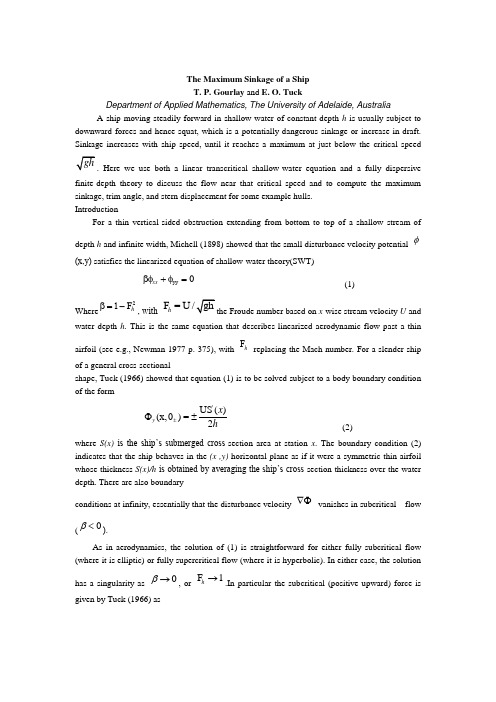
The Maximum Sinkage of a ShipT. P. Gourlay and E. O. TuckDepartment of Applied Mathematics, TheUniversity of Adelaide, AustraliaA ship moving steadily forward in shallow water of constant depth h is usually subject to downward forces and hence squat, which is a potentially dangerous sinkage or increase in draft. Sinkage increases with ship speed, until it reaches a maximum at just below the critical speedHere we use both a linear transcritical shallow-water equation and a fully dispersive finite-depth theory to discuss the flow near that critical speed and to compute the maximum sinkage, trim angle, and stern displacement for some example hulls.IntroductionFor a thin vertical-sided obstruction extending from bottom to top of a shallow stream of depth h and infinite width, Michell (1898) showed that the small disturbance velocity potential φ(x,y)satisfies the linearized equation of shallow-water theory(SWT)yy 0xx βφ + φ= (1)Where 2F h β=1-, with F =U /h x -wise stream velocity U and water depth h . This is the same equation that describes linearized aerodynamic flow past a thin airfoil (see e.g., Newman 1977 p. 375), with F h replacing the Mach number. For a slender ship of a general cross-sectionalshape, Tuck (1966) showed that equation (1) is to be solved subject to a body boundary condition of the form'US ()(x,0)=2y x h ±Φ± (2)where S(x) is the ship’s submerged cross -section area at station x . The boundary condition (2) indicates that the ship behaves in the (x ,y) horizontal plane as if it were a symmetric thin airfoil whose thickness S(x)/h is obtained by averaging the ship’s cross -section thickness over the water depth. There are also boundaryconditions at infinity, essentially that the disturbance velocity ∇Φ vanishes in subcritical flow(0β<).As in aerodynamics, the solution of (1) is straightforward for either fully subcritical flow (where it is elliptic) or fully supercritical flow (where it is hyperbolic). In either case, the solutionhas a singularity as 0β→, or F 1h →.In particular the subcritical (positive upward) force isgiven by Tuck (1966) as2F =B'(x)S'()log dxd x ξξξ- (3)with B(x) the local beam at station x . Here and subsequently the integrations are over the wetted length of the ship, i.e.,22L L X -<<where L is the ship’s waterline length. This force F is usually negative, i.e., downward, and for a fore-aft symmetric ship, theresulting midship sinkage is given hydrostatically by22S V s C L ⎛⎫= ⎪⎝⎭ (4) where ()V S x dx =⎰is the ship’s displaced volume, and2'()'()log 2s W L C dxd B x S x A Vξξξπ=-⎰⎰ (5) where ()w A B x dx =⎰is the ship’s waterplane area. The nondimensional coefficient 1.4s C ≈ has been shown by Tuck &Taylor(1970) to be almost a universal constant, depending only weakly on the ship’s hull shape.Hence the sinkage appears according to this linear dispersionless theory to tend to infinity as 1h F →.However, in practice, there are dispersive effects near 1h F = which limit the sinkage, and which cause it to reach a maximum value at just below the critical speed.Accurate full-scale experimental data for maximum sinkage are scarce. However,, according to linear inviscid theory, the maximum sinkage is directly proportional to the ship length for a given shape of ship and depth-to-draft ratio (see later). This means that model experiments for maximum sinkage (e.g., Graff et al 1964) can be scaled proportionally to length to yield full-scale results, provided the depth-to-draft ratio remains the same.The magnitude of this maximum sinkage is considerable. For example, the Taylor Series A3 model studied by Graff et al (1964) had a maximum sinkage of 0.89% of the ship length for the depth-to-draft ratio h/T = 4.0. This corresponds to a midship sinkage of 1.88 meters for a 200 meter ship. Experiments on maximum squat were also performed by Du & Millward (1991) using NPL round bilge series hulls. They obtained a maximum midship sinkage of 1.4% of the ship length for model 150B with h/T =2.3. This corresponds to 2.8 meters midship sinkage for a 200 meter ship. Taking into account the fact that there is usually a significant bow-up trim angle at the speed where the maximum sinkage occurs, the downward displacement of the stern can be even greater, of the order of 4 meters or more for a 200-meter long ship.It is important to note that only ships that are capable of traveling at transcritical Froude numbers will ever reach this maximum sinkage. Therefore, maximum sinkage predictions will be less relevant for slower ships such as tankers or bulk carriers. Since the ships or catamarans that frequently travel at transcritical Froude numbers are usually comparatively slender, we expect that slender-body theory will provide good results for the maximum sinkage of these ships.For ships traveling in channels, the width of the channel becomes increasingly importantaround 1h F =when the flow is unsteady and solitons are emitted forward of the ship (see e.g.,Wu& Wu 1982). Hence experiments performed in channels cannot be used to accurately predict maximum sinkage for ships in open water. The experiments of Graff et al were done in a wide tank, approximately 36 times the model beam, and are the best results available with which to compare an open-water theory. However, even with this large tank width, sidewalls still affect the flow near 1h F =, as we shall discuss.Transcritical shallow-water theory (TSWT)It is not possible simply to set ‚0β= in (1) in order to gain useful information about the flow near 1h F =. As with transonic aerodynamics, it is necessary to include other terms that have been neglected in the linearized derivation of SWT (1).An approach suggested by Mei (1976) (see also Mei & Choi,1987) is to derive an evolution equation of Korteweg-de Varies (KdV) type for the flow near 1h F =. The usual one-dimensional forms of such equations contain both nonlinear and dispersive terms. It is not difficult to incorporate the second space dimension y into the derivation, resulting in a two-dimensional KdV equation, which generalizes (1) by adding two terms to give231h 03xx yy X XX xxxx U βΦ+Φ-ΦΦ+Φ= (6) The nonlinear term in X XX ΦΦbut not the dispersive term inxxxx Φwas included by Lea & Feldman (1972). Further solutions of this nonlinear but nondispersive equation were obtained by Ang (1993) for a ship in a channel. Chen & Sharma (1995) considered the unsteady problem of soliton generation by a ship in a channel, using the Kadomtsev-Petviashvili equation, which is essentially an unsteady version of equation (6). Although they concentrated on finite-width domains, their method is also applicable to open water, albeit computationally intensive. Further nonlinear and dispersive terms were included by Chen (1999), allowing finite-width results to be computed over a larger range of Froude numbers.Mei (1976) considered the full equation (6) in open water and provided an analytic solution for the linear case where the term X XX ΦΦis omitted. He showed that for sufficiently slender ships the nonlinear term in equation (6) is of less importance than the dispersive term and can be neglected; also that the reverse is true for full-form ships where the nonlinear term is dominant. This is also discussed in Gourlay (2000).As stated earlier, most ships that are capable of traveling at transcritical speeds are comparatively slender. For these ships it is dispersion, not nonlinearity, that limits the sinkage in open water. Nonlinearity is usually included in one-dimensional KdV equations by necessity, as a steepening agent to provide a balance to the broadening effect of the dispersive term in xxxx Φ.Inopen water, however, there is already an adequate balance with the two-dimensional term in yyΦ.This is in contrast to finite-width domains, which tend to amplify transcritical effects and cause the flow to be more nearly unidirectional. Hence nonlinearity becomes important in finite-width channels to such an extent that steady flow becomes impossible in a narrow range of speeds close to critical (see e.g., Constantine 1961, Wu & Wu 1982).Therefore, for slender ships in shallow water of large or in finite width, we can solve for maximum squat using the simple transcritical shallow-water (TSWT) equation0xx yy xxxx βγΦ+Φ+Φ= (7) (Writing23h γ=), subject to the same boundary condition (2). The term in ƒ provides dispersion that was absent in the SWT,and limits the maximum sinkage.ConclusionsWe have used two slender-body methods to solve for the sinkage and trim of a ship traveling at arbitrary Froude number, including the transcritical region.The transcritical shallow water theory (TSWT) developed by Mei (1976) has been extended and exploited numerically, using numerical Fourier transform methods to give sinkage and trim via a double numerical integration. This theory has also been extended to the case of a ship moving in a channel of finite width; however, the numerical difficulty in computing the resulting force integral, and its limited validity, mean that the open-water theory is more practically useful.The finite-depth theory (FDT) developed by Tuck & Taylor (1970) has also been improved and used for general hull shapes. This theory gives a sinkage force and trim moment that are slightly oscillatory in h F . Since the theory involves summing infinite-depth and finite-depthcontributions, both of which vary with 2U at high Froude numbers, any error will growapproximately quadratically with U . Therefore we cannot use this theory at large supercritical Froude numbers. Also, the difficulty in finding the infinite-depth contributions numerically, as well as the extra numerical integration needed to compute the force and moment, make the FDT slightly more dif. cult to implement than TSWT.In practice, scenarios in which ships are at risk of grounding will normally have h/L <0.125. Since the TSWT is a shallow water theory and it works well at h/L = 0.125, we expect that it will give even better results at smaller, practically useful values of h=L . Also, since the TSWT and FDT give almost identical results for h/L <0.125, and the TSWT is a much simpler theory, we recommend it as a simple and accurate method for predicting transcritical squat in open water.备注:T.P.Gourlay and E.O.Tuck .The Maximum Sinkage of a ship[J].Jourmal of Ship Research ,2001.50~58<文献翻译二:译文>船舶最大下沉量T. P. Gourlay and E. O. Tuck澳大利亚阿德莱德大学一艘在等深为h 的浅水中平稳前行的船舶通常趋向于受到向下的合力并产生船体下沉,处我们同时利用”线性跨临界浅水方程”和”完全分散限深理论”研究典型船体在接近临界速度时的水流和计算这些船体的最大下沉量、纵倾角和船尾位移。
轴类毕业设计英文翻译、外文文献翻译
轴类毕业设计英文翻译、外文文献翻译ShaftSolid shafts. As a machine component a shaft is commonly a cylindrical bar that supports and rotates with devices for receiving and delivering rotary motion and torque .The crankshaft of a reciprocating engine receive its rotary motion from each of the cranks, via the pistons and connecting roads the slider-crank mechanisms , and delivers it by means of couplings, gears, chains or belts to the transmission, camshaft, pumps, and other devices. The camshafts, driven by a gear or chain from the crankshaft, has only one receiver or input, but each cam on the shaft delivers rotary motion to the valve-actuating mechanisms.An axle is usually defined as a stationary cylindrical member on which wheels and pulleys can rotate, but the rotating shafts that drive the rear wheels of an automobile are also called axles, no doubt a carryover from horse-and-buggy days. It is common practice to speak short shafts on machines as spindles, especially tool-carrying or work-carrying shafts on machine tools.In the days when all machines in a shop were driven by one large electric motor or prime mover, it was necessary to have long line shafts running length of the shop and supplying power, by belt, to shorter coutershafts, jack shafts, or head shafts. These lineshafts were assembled form separate lengths of shafting clampled together by rigid couplings. Although it is usually more convenient to drive each machine with a separate electric motor, and the present-day trend is in this direction, there are still some oil engine receives its rotary motion from each of the cranks, via the pistons and connecting roads the slider-crank mechanisms , and delivers it by means of couplings, gears, chains or belts to the transmission, camshaft, pumps, and other devices. The camshafts, driven by a gear or chain from the crankshaft, has only one receiver or input, but each cam on the shaft delivers rotary motion to the valve-actuating mechanisms.An axle is usually defined as a stationary cylindrical member on which wheels and pulleys can rotate, but the rotating shafts that drive the rear wheels of an automobile are also called axles, no doubt a carryover from horse-and-buggy days. It is common practice to speak short shafts on machines as spindles, especially tool-carrying or work-carrying shafts on machine tools.In the days when all machines in a shop were driven by one large electric motor or prime mover, it was necessary to have long line shafts running length of the shop and supplying power, by belt, to shorter coutershafts, jackshafts, or headshafts. These line shafts were assembled form separate lengths of shafting clampled together by rigid couplings.Although it is usually more convenient to drive each machine with a separate electric motor, and the present-day trend is in this direction, there are still some situation in which a group drive is more economical.A single-throw crankshaft that could be used in a single-cylinder reciprocating engine or pump is shown in Figure 21. The journals A andB rotate in the main bearings,C is the crankpin that fits in a bearing on the end of the connecting rod and moves on a circle of radius R about the main bearings, whileD andE are the cheeks or webs.The throw R is one half the stroks of the piston, which is connected, by the wrist pin, to the other end of the connecting rod and guided so as to move on a straight path passing throw the axis XX. On a multiple-cylinder engine the crankshaft has multiple throws---eight for a straight eight and for a V-8---arranged in a suitable angular relationship.Stress and strains. In operation, shafts are subjected to a shearing stress, whose magnitude depends on the torque and the dimensions of the cross section. This stress is a measure of resistance that the shaft material offers to the applied torque. All shafts that transmit a torque are subjected to torsional shearing stresses.In addition to the shearing stresses, twisted shafts are also subjected to shearing distortions. The distorted state is usually defined by the angle of tw。
- 1、下载文档前请自行甄别文档内容的完整性,平台不提供额外的编辑、内容补充、找答案等附加服务。
- 2、"仅部分预览"的文档,不可在线预览部分如存在完整性等问题,可反馈申请退款(可完整预览的文档不适用该条件!)。
- 3、如文档侵犯您的权益,请联系客服反馈,我们会尽快为您处理(人工客服工作时间:9:00-18:30)。
一种评估集装箱船结构扭转强度的实用方法K. Iijima, T. Shigemi, R. Miyake_, A. Kumano日本海事协会研究所(NK)摘要集装箱船结构的特点是舱口开口大。
由于这种结构特性,波中复杂的扭力矩影响会引起舱口开口的巨大角变形和翘曲压力。
这就需要在集装箱船的结构设计阶段评估船体梁的扭转强度。
本文在最新分析结果的基础上讨论了一种评估集装箱船结构扭转强度的实用方法。
为了尽可能准确估计扭响应特性,采用在油轮试验中已得到确认的三维兰金源法估计集装箱船的波载荷,并以此用有限元法分析整船模型。
另外,指定集装箱船扭转反应达到最大时的主导规则波条件。
扭转强度评估设计使用荷载,其产生的扭转反应等于长期预测值,并以指定主导波条件下的几个集装箱船的扭力矩为基础检测设计荷载。
同时讨论了用于估计总船体梁应力的一个适当的应力分量组合。
【关键词】:集装箱船扭转强度兰金源法水池试验设计荷载组合应力1.绪论受经济规模影响,集装箱船的体积正在加大。
最近几年集装箱船的发展似乎在加速。
10年前装载容量最大的5500标箱级集装箱船已多少成为目前的标准。
现今,最大的超巴拿马型集装箱船拥有超过8000标箱的容量,甚至12500标箱级集装箱船的基础研究设计已经开始。
[1]Payer[2]讨论了集装箱船在技术和经济方面的发展和转变。
论及集装箱船的顶级技术难题莫过于船体梁的扭转强度,即指,以大舱口开口为特点的集装箱船在波中会受到相当大的扭转变形和翘曲压力。
在这方面,Sun and Soares[3]开创性的研究了带有大舱口开口的船体承受扭力矩的极限强度。
翘曲应力分量应与其他应力分量(例如纵向弯曲应力和横向弯曲应力)一起纳入船体强度评估的考虑范围。
扭转变形可能在舱口角引起集中压力,因此舱口角的设计应考虑到疲劳强度。
众多关于集装箱船结构的研究从构造和流体力学两个方面分析了扭转强度,例如,[4–10],Shimizu [5,8]用一个梁变截面模拟集装箱船的结构,进行了流体力学和构造分析。
Nakata [6] and Umezaki [7]分别开发了一个总系统,在该系统中船舶运动分析和结构分析与统计分析相结合。
扭转变形受到扭力矩分布和船舶结构刚性参数分布的影响,而纵向或横向弯曲应力只决定于影响该部分剖面模数的相关位置的弯力矩振幅。
接着分析扭转响应时需要总船模型。
再者,扭力矩分析的准确性不仅与规模有关也与分布有关。
正如纵向弯曲应力在不同阶段具有差异,横向弯曲应力和翘曲应力也对总船体梁应力的估计有重大影响。
同时还要求分析复杂的波浪荷载。
因此,数值波浪荷载分析和有限元分析已被用于开发新的集装箱船以及创新设计的集装箱船。
从这个意义上说,集装箱船结构的发展主要依赖于这些数值分析。
另一方面,不能否认的是,船级社为船体梁结构强度评估制定的设计荷载已成为集装箱船设计的标准荷载,应用方便。
这就是说扭转响应估计的准确性、最后的结构标注以及船体的安全性,很大程度上都取决于设计荷载的精确性。
因此,需要发展用于评估扭转变形的设计荷载,以反映最新数值分析得到的准确结果。
利用这个设计荷载在不进行复杂的波浪荷载分析时就能得到更准确的集装箱船体扭曲强度评价,并推进船舶的结构安全。
为了使设计荷载数据可靠,让船舶设计师信服,其设计过程就应该透明和合理。
在一份合著[11]中提出,已经成功开发了针对油轮和货轮主要结构构件的设计荷载估算方法,这些船舶运营商都有透明和一致的背景。
相关资料讨论了设计海况、设计波和设计荷载之间的关系,最后结果表明以下方法得到的设计荷载可使所得响应可能等同于长期预测响应值。
目前,我们的目标是得到一个切实可行的方法,就是在尽可能准确分析得到的结果的基础上评估透明和一致背景下的扭转强度。
主要讨论了评估集装箱船船体梁扭转强度所需的设计荷载和最佳应力分量组合。
研究步骤如下:⑴建立波荷载估算方法:尽管有几例实验研究了集装箱船的扭力矩,但似乎无一针对超巴拿马型集装箱船。
水池试验中第一次得到验证的数值分析法在一份合著中有了发展。
⑵精确结构分析:第一个计算波浪中集装箱船的扭力矩,然后将荷载直接应用于整船的有限元模型。
确定翘曲压力和相对变形的响应函数,同时确定短期和长期(超越概率Q=10-8)预测值。
⑶提出和校正设计荷载:参照响应函数指定主导规则波条件下集装箱船的最大扭转变形。
计算10艘不同大小的集装箱船在主导波条件下的扭力矩,以该结果为依据制定设计荷载,并将其所得响应与步骤⑵中得到的长期预测值进行比较。
⑷提出和校正应力分量组合:步骤⑵后计算纵向应力分量、横向应力分量和总船梁应力的响应函数,严格审查不同阶段的应力分量。
参照响应函数之间的关系提出最佳应力分量组合,依此得到总船梁压力。
将所得总船梁压力与长期预测值进行比较,并严格审查不同阶段的应力分量。
⑸基于上述提出评估扭转强度的实用方法。
2.波荷载估算2.1 各种数值分析方法的优缺点多种带状法[12,13]已被开发和运用于估算波浪引起的船舶运动和包括纵向弯曲力矩和横向弯曲力矩在内的波荷载,该法有足够的准确度,实际应用性强。
带状法作为一个标准工具被广泛应用于估算非线性荷载和运动14,现在有时也估算船体结构的弹性15-17。
但是,因为它们没有准确考虑纵向带之间反射波的水动力干扰效应和立体效应,在短波估算时其准确性值得怀疑。
为了提高估算的准确性,尤其在短波条件下的准确性,已经提出许过考虑三维效应的数值分析方法。
其中包括基于三维势流理论提出的三维Green函数法18和兰金源法19-21。
这些方法的优势在于考虑三维效应,有良好的计算稳定性和适中的计算时间。
因此,它们有望作为方便的设计工具而取代带状法。
尽管大部分三维法最初是为了频域仿真,但它们很快发展为分析方法,与同时提升的计算机能力一起为时域仿真22-23效力。
这促进了非线性效应在时域仿真上的应用,同时出现的还有波浪振幅限度以及可能对设计荷载估算有重大影响的船舶运动。
这些方法的缺点之一是仍然需要耗费大量的计算时间。
一份合著显示,计算流体力学(CFD)可更准确的估算涉及波浪限度和运动振幅的波荷载。
自从改法直接从数值上解决了Navier-stokes方程,即使是高度非线性现象,如抨击和绿水航运都可纳入考虑范围。
尽管这种方法不够成熟,因为它才刚刚开始,但它有望作为估算波荷载和最终方法。
上述方法的优缺点见表1。
考虑到准确性、稳定性、计算时间以及和长期预测法的兼容性,本文采取了基于频域和三维势流理论的估算方法。
非线性特性及波浪限度、运动振幅则是利用了大浪条件下油轮测试得到的结果。
表1各种估算船体梁响应数值法的优缺点A:线性带状法;B:频域三维势流理论;C:时域三维势流理论;D:CFD。
◎:很好;○:好/可考虑;△:不好;×:差/不考虑。
2.2 兰金源法表2集装箱船模型的主要情况图1 三个断面处的力用力传感器测量水池试验的波浪条件见表3。
该试验在常规波条件下进行,分别以三种不同的入射波高,10种波长,7七种入射波角度(以301为间隔从1801(顶头浪)到01(尾随浪))以及2种不同的船速。
短波范围内不能进行15米波高的水池试验,入射波会在这个高度破裂。
2.4 数值结果比较图2〔a〕—〔c〕表示了首斜浪(120°)中三个断面(站线为2.5,5.0和7.5处)响应函数振幅的比较,或所谓的扭力矩响应振幅算子的比较。
横坐标显示波长λ随船舶高度L(λ/L)而变化的情况,纵坐标则显示单位波幅的扭力矩振幅。
试验结果利用傅里叶函数进行分析,因此,水池试验值表明元件振幅周期与遭遇波周期相同。
图中,“Exp.(3.5m)”, “Exp.(9.0m)”, “Exp.(15.0m)”, “STRIP” and “Rankine”分别代表3种入射波高度条件下的试验结果,带状法及兰金源法分析结果。
计算力传感器纵向位置或略低于静止水位的扭力矩。
表3水池试验的波浪条件兰金源法得到的数值结果与3.5米波高时的试验结果有很好的一致性,尤其在短波范围内,如图2所示。
而带状法得到的数值结果则与试验结果有较大出入。
图2 站线2.5(a),5.0(b),7.5(c)处试验结果与数值分析法结果的比较。
数据还显示在首斜浪(120°)的更短波长范围内结果最大。
此外,船尾处(站线2.5)也比其他地方(站线5.0,7.5)的结果大。
2.5 波中扭力矩的非线性特性波浪高度使扭力矩具有非线性特征,继而造成如图2(a)–(c)中“Exp.(3.5m)”,“Exp.(9.0m)”and“Exp.(15.0m)”处试验结果的不同。
随着波浪高度的增加,船头尾处每单位入射波的扭力矩增大,显示出明显的非线性特征。
而船尾和船中间不同波高的三个值和扭力矩几乎相同,非线性特征微弱。
试验中利用扭力矩 RAOs 得到与船中间部位有关的剪力中心处短期和长期扭力矩预测值。
短期和长期预测分别用到了社科理事会1964波光谱(定向分配:余弦2)和国际船级社协会波数据(北大西洋,全年[29])。
采用福田康夫提出的方法作了长期预测。
然后,比较大波浪与线性小波浪中的长期扭力矩预测值,定量确定波荷载的定义为在代表线性因素的大、小波浪非线性相关系数。
非线性相关系数Cnonlinear条件下扭力矩长期预测值的比值。
( 1)其中[X max]Hw=9.0m and [X max]Hw=3.5m分别代表概率水平为10-8时波高9.0m和3.5m 条件下利用RAOs得到的扭力矩长期预测值。
因此,假定相关响应的试验结果在3.5m波高条件下呈线性关系,又因为短波范围内高15米的波浪会破碎,扭力矩会达到显著值,同时假定波高9m时非线性关系使扭力矩的增加量达到最大值。
表4显示了三个不同地点处(站线为2.5、5.0 和7.5)与扭力矩有关的非线性相关系数值。
由表可发现船中间和船尾(站线为2.5,5.0)处非线性特征不明显,而船头(站线为7.5)处扭力矩的非线性相关系数则非常大。
表4与波高有关的扭力矩非线性相关系数试验结果3.结构响应估计3.1 概述材料力学表明,在大断面梁上扭转响应和横向响应会发生耦合。
为了避免翘曲应力和横向弯曲应力发生耦合,要采用的标准程序是评估与船中间部位有关的扭力矩剪切中心,并定义翘曲应力为扭力矩下的船体梁应力。
但是,一个真正的而变化,故应力分量不能被完全分开。
另一方面,翘曲应力σWT也可定义为扣除横向弯曲应力后横向剪切应力和扭力矩下的船体梁应力,结构上可表达为σWT =σHS+σTM -σWH,其中σHS ,σTM 和σWH分别表示横向剪切应力、扭力矩和横向弯曲应力下的船体梁应力。
这一定义中,不需要假定剪切中心的高度。
通过研究计算,由第一个定义得到的翘曲应力的响应函数与第二个定义得到的结果几乎相同。