24-Interface recombination in amorphous crystalline silicon solar cells, a simulation study
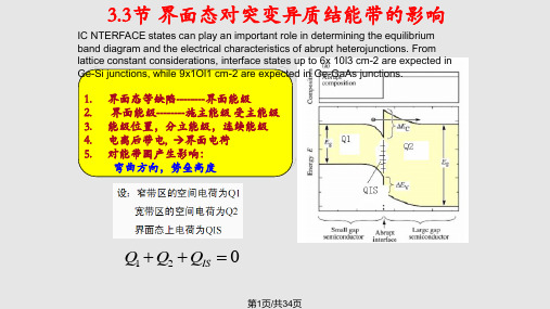
异质结的能带图剖析PPT课件
(4.17)
4.1.3 隧穿机制
J Js (T)exp(AV )
隧道电流表现出来的特点是lnJ-V 的曲线斜率和温度无关。
(4.18)
Lg(J)
T1 T2 T3
V 第22页/共34页
4.2 异质结的注入比
电子面临的势垒下降:VD-EC
空穴面临的势垒上4升. 2: V异D+质E结v 的 注 入 比
第8页/共34页
4.1突变异质结的伏安特性
ΔEC
(a) 低尖峰势垒 由n区扩散向结处的电子流可以 通过发射机制越过尖峰势垒进入 p区.因此异质pn 结的电流主要有 扩散机制决定-扩散模型.
qVD1 ΔEV
qVD2
( b) 高尖峰势垒
由n区扩散向结处的电子, 只有能量
高于势垒尖峰的才能通过发射机
qVD2
qV k0T
)
1]exp(
x1 Ln1
)
exp(
x Ln1
)
电子扩散电流密度
Jn qD | [exp( ) 1] d[n1(x)n10 ]
qDn1n10
qV
n1
dx
x x1 第1L5n页1 /共34页 k0T
(4.5)
p2从0 p型区p1价0 带ex底p到(n型(q区VDk价0T带E底v )的势垒高度(为4.6)
式中D为常数。 同质结:Eg=0,r=D。 异质结:r 随着Eg呈指数上升。 例如了E,七g=在十0.p3四-3Ge万VaA,倍s/结。N果在-A注同l0.3入样Ga比的0.7r正A高s向异达电质7.4压结×下中10,,5,可它因以们而获的注得入更比高提的高
注入电子浓度。
对于晶体管和半导体激光器等器件来说, “注人比” 是个很重要的物理量, 它决定晶体管的放大倍数 、激光器的注人效率和阐值电流密度, 因为总电流中 只有注人到基区或有源区中的少数载流子, 才对器件的 功能发挥真正的作用所以, 用异质结宽带隙材料作发射 极, 效率会很高, 这是异质结的特性之一
Common Phase Error due to Phase Noise in OFDM - Estimation and Suppression

COMMON PHASE ERROR DUE TO PHASE NOISE IN OFDM-ESTIMATION AND SUPPRESSIONDenis Petrovic,Wolfgang Rave and Gerhard FettweisV odafone Chair for Mobile Communications,Dresden University of Technology,Helmholtzstrasse18,Dresden,Germany{petrovic,rave,fettweis}@ifn.et.tu-dresden.deAbstract-Orthogonal frequency division multiplexing (OFDM)has already become a very attractive modulation scheme for many applications.Unfortunately OFDM is very sensitive to synchronization errors,one of them being phase noise,which is of great importance in modern WLAN systems which target high data rates and tend to use higher frequency bands because of the spectrum availability.In this paper we propose a linear Kalmanfilter as a means for tracking phase noise and its suppression.The algorithm is pilot based.The performance of the proposed method is investigated and compared with the performance of other known algorithms.Keywords-OFDM,Synchronization,Phase noise,WLANI.I NTRODUCTIONOFDM has been applied in a variety of digital commu-nications applications.It has been deployed in both wired systems(xDSL)and wireless LANs(IEEE802.11a).This is mainly due to the robustness to frequency selective fading. The basic principle of OFDM is to split a high data rate data stream into a number of lower rate streams which are transmitted simultaneously over a number of orthogonal subcarriers.However this most valuable feature,namely orthogonality between the carriers,is threatened by the presence of phase noise in oscillators.This is especially the case,if bandwidth efficient higher order modulations need to be employed or if the spacing between the carriers is to be reduced.To compensate for phase noise several methods have been proposed.These can be divided into time domain[1][2]and frequency domain approaches[3][4][5].In this paper we propose an algorithm for tracking the average phase noise offset also known as the common phase error(CPE)[6]in the frequency domain using a linear Kalmanfilter.Note that CPE estimation should be considered as afirst step within more sophisticated algorithms for phase noise suppression[5] which attempt to suppress also the intercarrier interference (ICI)due to phase noise.CPE compensation only,can however suffice for some system design scenarios to suppress phase noise to a satisfactory level.For these two reasons we consider CPE estimation as an important step for phase noise suppression.II.S YSTEM M ODELAn OFDM transmission system in the presence of phase noise is shown in Fig. 1.Since all phase noise sources can be mapped to the receiver side[7]we assume,without loss of generality that phase noise is present only at the front end of the receiver.Assuming perfect frequency and timing synchronization the received OFDM signal samples, sampled at frequency f s,in the presence of phase noise can be expressed as r(n)=(x(n) h(n))e jφ(n)+ξ(n).Each OFDM symbol is assumed to consist of a cyclic prefix of length N CP samples and N samples corresponding to the useful signal.The variables x(n),h(n)andφ(n)denote the samples of the transmitted signal,the channel impulse response and the phase noise process at the output of the mixer,respectively.The symbol stands for convolution. The termξ(n)represents AWGN noise with varianceσ2n. The phase noise processφ(t)is modelled as a Wiener process[8],the details of which are given below,with a certain3dB bandwidth∆f3dB.,0,1,2...m lX l=,0,1,2...m lR l=Fig.1Block diagram of an OFDM transmission chain.At the receiver after removing the N CP samples cor-responding to the cyclic prefix and taking the discrete Fourier transform(DFT)on the remaining N samples,the demodulated carrier amplitude R m,lkat subcarrier l k(l k= 0,1,...N−1)of the m th OFDM symbol is given as[4]:R m,lk=X m,lkH m,lkI m(0)+ζm,lk+ηm,lk(1)where X m,lk,H m,lkandηm,lkrepresent the transmitted symbol on subcarrier l k,the channel transfer function andlinearly transformed AWGN with unchanged variance σ2n at subcarrier l k ,respectively.The term ζm,l k represents intercarrier interference (ICI)due to phase noise and was shown to be a gaussian distributed,zero mean,randomvariable with variance σ2ICI =πN ∆f 3dB s[7].The term I m (0)also stems from phase noise.It does not depend on the subcarrier index and modifies all subcarriers of one OFDM symbol in the same manner.As its modulus is in addition very close to one [9],it can be seen as a symbol rotation in the complex plane.Thus it is referred to in the literature as the common phase error (CPE)[6].The constellation rotation due to CPE causes unaccept-able system performance [7].Acceptable performance can be achieved if one estimates I m (0)or its argument and compensates the effect of the CPE by derotating the received subcarrier symbols in the frequency domain (see Eq.(1)),which significantly reduces the error rate as compared to the case where no compensation is used.The problem of esti-mating the CPE was addressed by several authors [3][4][10].In [3]the authors concentrated on estimating the argument of I m (0)using a simple averaging over pilots.In [10]the argument of I m (0)was estimated using an extended Kalman filter,while in [4]the coefficient I m (0)itself was estimated using the LS algorithm.Here we introduce an alternative way for minimum mean square estimation (MMSE)[11]of I m (0)using a linear scalar Kalman filter.The algorithm is as [4]pilot based.III.P HASE N OISE M ODELFor our purposes we need to consider a discretized phase noise model φ(n )=φ(nT s )where n ∈N 0and T s =1/f s is the sampling period at the front end of the receiver.We adopt a Brownian motion model of the phase noise [8].The samples of the phase noise process are given as φ(n )=2πf c √cB (n )where f c is the carrier frequency,c =∆f 3dB /πf 2c [8]and B (n )represents the discretizied Brownian motion process,Using properties of the Brownian motion [12]the fol-lowing holds:B (0)=0and B (n +1)=B (n )+dB n ,n ∈N 0where each increment dB n is an independent random variable and dB n ∼√T s N (0,1).Noting that φ(n )=2πf c √cB (n )we can write the discrete time phase noise process equation asφ(n +1)=φ(n )+w (n )(2)where w (n )∼N (0,4π2f 2c cT s )is a gaussian randomvariable with zero mean and variance σ2w =4π2f 2c cT s .IV.CPE E STIMATION U SING A K ALMAN F ILTER Since all received subcarriers within one OFDM symbolare affected by the same factor,namely I m (0),the problem at hand can be seen as an example of estimating a constant from several noisy measurements given by Eq.(1)for which purpose a Kalman filter is well suited [11].For a Kalmanfilter to be used we need to define the state space model of the system.Define first the set L ={l 1,l 2,l 3,...l P }as a subset of the subcarrier set {0,1,...N −1}.Using Eq.(1)one can writeR m,l k =A m,l k I m,l k (0)+εm,l k(3)where A m,l k =X m,l k H m,l k and I m,l k (0)=I m (0)for all k =1,2...,P .Additional indexing of the CPE terms is done here only for convenience of notation.On the other hand one can writeI m,l k +1(0)=I m,l k (0).(4)Equations (3)and (4)are the measurement and processequation of the system state space model,where A m,l k represents the measurement matrix,while the process matrix is equal to 1and I m,l k (0)corresponds to the state of the system.The measuring noise is given by εm,l k which combines the ICI and AWGN terms in Eq.(1),the varianceof which for all l k equals σ2ε=(σ2ICI +σ2n ).The process noise equals zero.Note that the defined state space model is valid only for one OFDM symbol.For the state space model to be fully defined,knowledge of the A m,l k =X m,l k H m,l k is needed.Here we assume to have ideal knowledge of the channel.On the other hand we define the subset L to correspond to the pilot subcarrier locations within one OFDM symbol so that X m,q ,q ∈L are also known.We assume that at the beginning of each burst perfect timing and frequency synchronization is achieved,so that the phase error at the beginning of the burst equals zero.After the burst reception and demodulation,the demodulated symbols are one by one passed to the Kalman filter.For a Kalman filter initialization one needs for eachOFDM symbol an a priori value for ˆI m,l 1(0)and an a priori error variance K −m,1.At the beginning of the burst,when m =1,it is reasonable to adopt ˆI −1,l 1(0)=1.Within each OFDM symbol,say m th,the filter uses P received pilot subcarriers to recursively update the a priori value ˆI −1m,l 1(0).After all P pilot subcarriers are taken into account ˆI m,l P (0)is obtained,which is adopted as an estimate ofthe CPE within one OFDM symbol,denoted as ˆIm (0).The Kalman filter also provides an error variance of the estimateof I m,l P (0)as K m,P .ˆI m,l P(0)and K m,P are then used as a priori measures for the next OFDM symbol.The detailed structure of the algorithm is as follows.Step 1:InitializationˆI −m,l 1(0)=E {I −m,l 1(0)}=ˆI m −1(0)K −m,1=E {|I m (0)−ˆIm −1(0)|2}∼=E {|φm −ˆφm −1|2}=σ2CP E +K m −1,Pwhere σ2CP E =4π2N 2+13N +N CP ∆f 3dBf s(see [10]),K 0,P =0and φm =arg {I m (0)}.Repeat Step2and Step3for k=1,2,...,P Step2:a-posteriori estimation(update)G m,k=K−m,kH H m,lkH m,lkK−m,kH Hm,l k+(σ2ICI+σ2n)ˆIm,l k (0)=ˆI−m,l k(0)+G m,k[R m,lk−H m,l kˆI−m,l k(0)]K m,k=(1−G m,k H m,lk )K−m,kStep3:State and error variance propagationK−m,k+1=K m,k(5)ˆI−m,l k+1(0)=ˆI m,lk(0)Note that no matrix inversions are required,since the state space model is purely scalar.V.CPE C ORRECTIONThe easiest approach for CPE correction is to derotate all subcarriers l k of the received m th symbol R m,lkby φm=−arg{ˆI m(0)}.Unambiguity of the arg{·}function plays here no role since any unambiguity which is a multiple of2πrotates the constellation to its equivalent position in terms of its argument.The presented Kalmanfilter estimation algorithm is read-ily applicable for the decision feedback(DF)type of algo-rithm presented in[4].The idea there was to use the data symbols demodulated after thefirst CPE correction in a DFE manner to improve the quality of the estimate since that is increasing the number of observations of the quantity we want to estimate.In our case that would mean that after thefirst CPE correction the set L={l1,l2,l3,...l P}of the subcarriers used for CPE estimation,which previously corresponded to pilot subcarriers,is now extended to a larger set corresponding to all or some of the demodulated symbols. In this paper we have extended the set to all demodulated symbols.The Kalmanfilter estimation is then applied in an unchanged form for a larger set L.VI.N UMERICAL R ESULTSThe performance of the proposed algorithm is investigated and compared with the proposal of[4]which is shown to outperform other known approaches.The system model is according to the IEEE802.11a standard,where64-QAM modulation is used.We investigate the performance in AWGN channels and frequency selective channels using as an example the ETSI HiperLAN A-Channel(ETSI A). Transmission of10OFDM symbols per burst is assumed.A.Properties of an EstimatorThe quality of an estimation is investigated in terms of the mean square error(MSE)of the estimator for a range of phase noise bandwidths∆f3dB∈[10÷800]Hz.Table1 can be used to relate the phase noise bandwidth with other quantities.Figures2and3compare the MSE of the LS estimator from[4]and our approach for two channel types and both standard correction and using decision feedback. Note that SNRs are chosen such that the BER of a coded system after the Viterbi algorithm in case of phase noise free transmission is around1·10−4.Kalmanfilter shows better performance in all cases and seems to be more effective for small phase noise bandwidths. As expected when DF is used the MSE of an estimator is smaller because we are taking more measurements into account.Fig.2MSE of an estimator for AWGN channel.Fig.3MSE of an estimator for ETSI A channel.Table 1Useful relationsQuantitySymbolRelationTypical values for IEEE802.11aOscillator constant c [1radHz]8.2·10−19÷4.7·10−18Oscillator 3dB bandwidth ∆f 3dB [Hz]∆f 3dB =πf 2cc 70÷400Relative 3dB bandwidth ∆f 3dB ∆f car∆f 3dBfsN 2·10−4÷13·10−4Phase noise energy E PN [rad]E PN =4π∆f 3dB∆fcar0.0028÷0.016Subcarrier spacing∆f car∆f car =f s N312500HzB.Symbol Error Rate DegradationSymbol error rate (SER)degradation due to phase noise is investigated also for a range of phase noise bandwidths ∆f 3dB ∈[10÷800]Hz and compared for different correc-tion algorithms.Ideal CPE correction corresponds to the case when genie CPE values are available.In all cases simpleconstellation derotation with φ=−arg {ˆIm (0)}is used.Fig.4SER degradation for AWGN channel.In Figs.4and 5SER degradation for AWGN and ETSI A channels is plotted,respectively.It is interesting to note that as opposed to the ETSI A channel case in AWGN channel there is a gap between the ideal CPE and both correction approaches.This can be explained if we go back to Eq.(1)where we have seen that phase noise affects the constellation as additive noise.Estimation error of phase noise affects the constellation also in an additive manner.On the other hand the SER curve without phase noise in the AWGN case is much steeper than the corresponding one for the ETSI A channel.A small SNR degradation due to estimation errors will cause therefore large SER variations.This explains why the performance differs much less in the ETSI A channel case.Generally from this discussion a conclusion can be drawn that systems with large order of diversity are more sensitive to CPE estimation errors.Note that this ismeantFig.5SER degradation for ETSI A channel.not in terms of frequency diversity but the SER vs.SNR having closely exponential dependence.It can be seen that our approach shows slightly better performance than [4]especially for small phase noise bandwidths.What is also interesting to note is,that DF is not necessary in the case of ETSI A types of channels (small slope of SER vs.SNR)while in case of AWGN (large slope)it brings performance improvement.VII.C ONCLUSIONSWe investigated the application of a linear Kalman filter as a means for tracking phase noise and its suppression.The proposed algorithm is of low complexity and its performance was studied in terms of the mean square error (MSE)of an estimator and SER degradation.The performance of an algorithm is compared with other algorithms showing equivalent and in some cases better performance.R EFERENCES[1]R.A.Casas,S.Biracree,and A.Youtz,“Time DomainPhase Noise Correction for OFDM Signals,”IEEE Trans.on Broadcasting ,vol.48,no.3,2002.[2]M.S.El-Tanany,Y.Wu,and L.Hazy,“Analytical Mod-eling and Simulation of Phase Noise Interference in OFDM-based Digital Television Terrestial Broadcast-ing Systems,”IEEE Trans.on Broadcasting,vol.47, no.3,2001.[3]P.Robertson and S.Kaiser,“Analysis of the effects ofphase noise in OFDM systems,”in Proc.ICC,1995.[4]S.Wu and Y.Bar-Ness,“A Phase Noise SuppressionAlgorithm for OFDM-Based WLANs,”IEEE Commu-nications Letters,vol.44,May1998.[5]D.Petrovic,W.Rave,and G.Fettweis,“Phase NoiseSuppression in OFDM including Intercarrier Interfer-ence,”in Proc.Intl.OFDM Workshop(InOWo)03, pp.219–224,2003.[6]A.Armada,“Understanding the Effects of PhaseNoise in Orthogonal Frequency Division Multiplexing (OFDM),”IEEE Trans.on Broadcasting,vol.47,no.2, 2001.[7]E.Costa and S.Pupolin,“M-QAM-OFDM SystemPerformance in the Presence of a Nonlinear Amplifier and Phase Noise,”IEEE mun.,vol.50, no.3,2002.[8]A.Demir,A.Mehrotra,and J.Roychowdhury,“PhaseNoise in Oscillators:A Unifying Theory and Numerical Methods for Characterisation,”IEEE Trans.Circuits Syst.I,vol.47,May2000.[9]S.Wu and Y.Bar-ness,“Performance Analysis of theEffect of Phase Noise in OFDM Systems,”in IEEE 7th ISSSTA,2002.[10]D.Petrovic,W.Rave,and G.Fettweis,“Phase NoiseSuppression in OFDM using a Kalman Filter,”in Proc.WPMC,2003.[11]S.M.Kay,Fundamentals of Statistical Signal Process-ing vol.1.Prentice-Hall,1998.[12]D.J.Higham,“An Algorithmic Introduction to Numer-ical Simulation of Stochastic Differential Equations,”SIAM Review,vol.43,no.3,pp.525–546,2001.。
heterogeneous interfacial structure

heterogeneous interfacial structure英文版Heterogeneous Interfacial StructureHeterogeneous interfacial structure refers to the structural differences that exist at the boundary between two different materials or phases. This structure plays a crucial role in determining the physical and chemical properties of the interface, as well as its stability and reactivity.At the interface between two materials, the atomic arrangement, bonding configuration, and electronic structure can all differ significantly from the bulk materials on either side. This heterogeneity can lead to a range of unique properties, such as charge accumulation, bond formation, and catalytic activity. For example, in the field of materials science, heterogeneous interfaces are often exploited to enhance the performance of devices such as solar cells and fuel cells.The study of heterogeneous interfacial structure is challenging due to the complexity of the interactions involved. Experimental techniques such as scanning probe microscopy, spectroscopy, and diffraction methods can provide insights into the atomic-scale structure and electronic properties of interfaces. Computational modeling is also an important tool for understanding and predicting interfacial behavior.In recent years, there has been increasing interest in the use of heterogeneous interfacial structures in nanotechnology and materials science. This interest is driven by the potential for novel materials with enhanced properties, as well as the development of new technologies such as nanodevices and sensors.In conclusion, heterogeneous interfacial structure is a crucial aspect of materials science and nanotechnology. Its understanding and control offer the potential for the development of novel materials and devices with enhanced performance and functionality.中文版异质界面结构异质界面结构指的是两种不同材料或相之间的边界处存在的结构差异。
qcm 天平

ABSTRACT: Quartz crystal microbalance with dissipation monitoring (QCM-D) was employed to characterize the adsorption of the model proteins, bovine serum albumin (BSA) and fibronectin (FN), to polypyrrole doped with dextran sulfate (PPy−DS) as a function of DS loading and surface roughness. BSA adsorption was greater on surfaces of increased roughness and was above what could be explained by the increase in surface area alone. Furthermore, the additional mass adsorbed on the rough films was concomitant with an increase in the rigidity of the protein layer. Analysis of the dynamic viscoelastic properties of the protein adlayer reveal BSA adsorption on the rough films occurs in two phases: (1) arrival and initial adsorption of protein to the polymer surface and (2) postadsorption molecular rearrangement to a more dehydrated and compact conformation that facilitates further recruitment of protein to the polymer interface, likely forming a multilayer. In contrast, FN adsorption was independent of surface roughness. However, films prepared from solutions containing the highest concentration of DS (20 mg/ mL) demonstrated both an increase in adsorbed mass and adlayer viscoelasticity. This is attributed to the higher DS loading in the conducting polymer film resulting in presentation of a more hydrated molecular structure indicative of a more unfolded and bioactive conformation. Modulating the redox state of the PPy−DS polymers was shown to modify both the adsorbed mass and viscoelastic nature of FN adlayers. An oxidizing potential increased both the total adsorbed mass and the adlayer viscoelasticity. Our findings demonstrate that modification of polymer physicochemical and redox condition alters the nature of protein− polymer interaction, a process that may be exploited to tailor the bioactivity of protein through which interactions with cells and tissues may be controlled.
二维二氧化钛材料
architectonics
(MANA),
National Institute for Materials
Science, Tsukuba, Japan. His
current research interests focus
on physical properties of oxide
nanosheets.
FEATURE ARTICLE
/materials | Journal of Materials Chemistry
Exfoliated oxide nanosheets: new solution to nanoelectronics†
Minoru Osada*ab and Takayoshi Sasaki*ab
One of the most important and attractive aspects of the exfoliated nanosheets is that various nanostructures can be fabricated using them as 2D building blocks.32–38 It is even possible to tailor superlattice-like assemblies, incorporating into the nanosheet galleries a wide range of materials39–45 such as organic molecules, polymers, and inorganic and metal nanoparticles. Sophisticated functionalities or nanodevices may be designed through the selection of nanosheets and combining materials, and precise control over their arrangement at the molecular scale. In this context, many projected applications in
Recombination of Intersecting D-branes in Tachyon Field Theory
E-mail: whhwung@.tw
1
1ቤተ መጻሕፍቲ ባይዱ
Introduction
Branes and their different configurations are known to play important roles in the unified formulation of nonperturbative string/M theory [1-4]. Brane configurations that contain tachyonic model are unstable and will decay. The decay models vary depending on the unstable brane configurations. In a series of papers, Sen had made several conjectures on tachyon condensation [5] which have drawn attention to various non-BPS D-brane configurations in string theory [6-10]. According to the conjectures the potential height of the tachyon potential exactly cancels the tension of the original unstable D-brane and, at the stable true vacuum, the original D-brane disappears and the kink-type tachyon condensed states correspond to lower-dimensional D-branes. One of the interesting D-brane configurations is a pair of D-branes intersecting at an angle [11-14]. Such a scenario of intersecting branes is known to be possible to construct models similar to the standard model [15] and may provide a simple mechanism for inflation in the early universe [16]. In this paper we will investigate the mechanism of recombination of intersection D-branes. Within the framework of the effective tachyon field theory [6-10] we describe how a pair of D-branes intersecting at an angle shall recombine. In the section II we briefly review the effective one-tachyon Lagrangian. In the section III we use the effective two-tachyon Lagrangian [9], in which the tachyon is described as a two-by-two matrix field, to study the diagonal fluctuation in the background of the kink solutions. The kink solutions in here are regarded as tachyon condensations of the non-BPS brane in higher dimension. As the tachyon condensated state represents a lower-dimensional BPS-brane, it is a stable configuration. Therefore the diagonal fluctuation in the background of the kink solutions will have no tachyonic mode. Then, as the main contain of this paper, we study the off-diagonal fluctuation in the background of the kink solutions. in this case as the D-branes (i.e. kinks) intersecting at an angle is unstable the off-diagonal fluctuation will have tachyonic mode. After diagonalizing the tachyonic matrix field we see that the eigenfunction can describe the new recombined branes. In the section IV we extend our method to discuss the general behavior of the recombination of intersection D-branes which possessing arbitrary function forms. We also present the physical reasons behind the mathematical process of diagonalizing the tachyonic matrix field. Note that in a recent paper Hashimoto and Nagaoka [14] had investigated the recombination of intersecting D-branes by using the super Yang-Mills theory which are low energy effective theories of D-branes. The Yang-Mills field therein represents the dynamics field on the branes while the Higgs fields represent the locations of the D-branes. Our investigations are within the framework of tachyon field theory, thus the dynamics field on the branes are
光纤通信英文版常见中英对照单词表
AAbsorption coefficient 吸收系数ac alternating current 交变电流交流Acoustic phonon 声学声子Active component 有源器件AM amplitude modulation 幅度调制AM,FM,PM:幅度/频率/相位调制AON all-optical network 全光网络AOTF acoustic optic tunable filter 声光调制器APD avalanche photodiode 雪崩二极管AR coatings antireflection coatings 抗反膜ASE amplified spontaneous emission 放大自发辐射ASK amplitude shift keying 幅移键控ASK/FSK/PSK 幅/频/相移键控ATM asynchronous transfer mode 异步转移模式Attenuation coefficient 衰减系数Attenuator 衰减器Auger recombination:俄歇复合AWG arrayed-waveguide grating 阵列波导光栅BBand gap:带隙Band pass filter 带通滤波器Beam divergence 光束发散BER bit error rate 误码率BER:误码率BH buried heterojunction 掩埋异质结Binary representation 二进制表示方法Binary 二进制Birefringence 双折射Birefringence双折射Bitrate-distance product 比特距离的乘积Block diagram 原理图Boltzman statistics:玻尔兹曼统计分布BPF band pass filter 带通滤波器Bragg condition 布拉格条件Bragg diffraction 布拉格衍射Brillouin scattering 布里渊散射Brillouin shift 布里渊频移Broad area 宽面Buried heterostructure 掩埋异质结CC3 cleaved-coupled cavity 解理耦合腔Carrier lifetime:载流子寿命CATV common antenna cable television 有线电视CDM code division multiplexing 码分复用Characteristics temperature 特征温度Chirp 啁啾Chirped Gaussian pulse 啁啾高斯脉冲Chromatic dispersion 色度色散Chromatic dispersion 色度色散Cladding layer:包层Cladding 包层CNR carrier to noise ratio 载噪比Conduction band:导带Confinement factor 限制因子Connector 连接头Core cladding interface 纤芯包层界面Core-cladding interface 芯层和包层界面Coupled cavity 耦合腔CPFSK continuous-phase frequency-shift keying 连续相位频移键控Cross-phase modulation 交叉相位调制Cross-talk 串音CSO Composite second order 复合二阶CSRZ:载波抑制归零码Cutoff condition 截止条件CVD chemical vapour deposition 化学汽相沉积CW continuous wave 连续波Cylindrical preform:预制棒DDBR distributed Bragg reflector 分布布拉格反射DBR: distributed Bragg reflector 分布式布拉格反射器dc direct current 直流DCF dispersion compensating fiber 色散补偿光纤Depressed-cladding fiber: 凹陷包层光纤DFB distributed feedback 分布反馈DFB: Distributed Feedback 分布式反馈Differential gain 微分增益Differential quantum efficiency 微分量子效率Differential-dispersion parameter:微分色散参数Diffusion 扩散Digital hierarchy 数字体系DIP dual in line package 双列直插Direct bandgap:直接带隙Directional coupler 定向耦合器Dispersion compensation fiber:色散补偿光纤Dispersion decreasing fiber:色散渐减光纤Dispersion parameter:色散参数Dispersion shifted fiber 色散位移光纤Dispersion slope 色散斜率Dispersion slope:色散斜率Dispersion-flatten fiber:色散平坦光纤Dispersion-shifted fiber:色散位移光纤Double heterojunction 双异质结Double heterostructure:双异质结Doubly clad:双包层DPSK differential phase-shift keying 差分相移键控Driving circuit 驱动电路Dry fiber 无水光纤DSF dispersion shift fiber 色散位移光纤DWDM dense wavelength divisionmultiplexing/multiplexer密集波分复用/器DWDM: dense wavelength division multiplexing密集波分复用E~GEDFA erbium doped fiber amplifier 掺铒光纤激光器Edge emitting LED 边发射LEDEdge-emitting 边发射Effective index 有效折射率Eigenvalue equation 本征值方程Elastic scattering 弹性散射Electron-hole pairs 电子空穴对Electron-hole recombination 电子空穴复合Electron-hole recombination:电子空穴复合Electrostriction 电致伸缩效应Ethernet 以太网External cavity 外腔External quantum efficiency 外量子效率Extinction ratio 消光比Eye diagram 眼图FBG fiber-bragg grating 光纤布拉格光栅FDDI fiber distributed data interface 光纤数据分配接口FDM frequency division multiplexing频分复用FDM:频分复用Fermi level 费米能级Fermi level:费米能级Fermi-Dirac distribution:费米狄拉克分布FET field effect transistor 场效应管Fiber Manufacturing:光纤制作Field radius 模场半径Filter 滤波器Flame hydrolysis 火焰裂解FM frequency modulation 频率调制Forward-biased :正向偏置FP Fabry Perot 法布里-珀落Free spectral range 自由光谱范围Free-space communication 自由空间光通信系统Fresnel transmissivity 菲涅耳透射率Front end 前端Furnace 熔炉FWHM full width at half maximum 半高全宽FWHM: 半高全宽FWM four-wave mixing 四波混频Gain coefficient 增益系数Gain coupled 增益耦合Gain-guided semiconductor laser 增益波导半导体激光器Germania 锗GIOF graded index optical fiber 渐变折射率分布Graded-index fiber 渐变折射率光纤Group index 群折射率GVD group-velocity dispersion 群速度色散GVD: 群速度色散H~LHBT heterojunction-bipolar transistor异质结双极晶体管HDTV high definition television 高清晰度电视Heavy doping:重掺杂Heavy-duty cable 重型光缆Heterodyne 外差Heterojunction:异质结HFC hybrid fiber-coaxial 混合光纤/电缆Higher-order dispersion 高阶色散Highpass filter 高通滤波器Homodyne 零差Homojunction:同质结IC integrated circuit 集成电路IM/DD intensity modulation with direct detection 强度调制直接探测IM/DD: 强度调制/直接探测IMD intermodulation distortion 交互调制失真Impulse 冲激Impurity 杂质Index-guided 折射率导引Indirect bandgap:非直接带隙Inelastic scattering 非弹性散射Inhomogeneous非均匀的Inline amplifier 在线放大器Intensity noise 强度噪声Intermodal dispersion:模间色散Intermode dispersion 模间色散Internal quantum efficiency:内量子效率Intramodal dispersion: 模内色散Intramode dispersion 模内色散Intrinsic absorption 本征吸收ISDN integrated services digital network 综合业务数字网ISI intersymbol interference 码间干扰Isotropic 各向同性Jacket 涂层Jitter 抖动Junction:结Kinetic energy:动能Lambertian source 朗伯光源LAN local-area network 局域网Large effective-area fiber 大有效面积发光Laser threshold 激光阈值Laser 激光器Lateral mode 侧模Lateral 侧向Lattice constant:晶格常数Launched power 发射功率LD laser diode 激光二极管LD:激光二极管LED light emitting diode 发光二极管LED: 发光二极管L-I light current 光电关系Light-duty cable 轻型光缆Linewidth enhancement factor 线宽加强因子Linewidth enhancement factor 线宽增强因子Linewidth 线宽Longitudinal mode 纵模Longitudinal model 纵模Lowpass filter 低通滤波器LPE liquid phase epitaxy 液相外延LPE:液相外延M~NMacrobending 宏弯MAN metropolitan-area network 城域网Material dispersion 材料色散Material dispersion:材料色散Maxwell’s equations 麦克斯韦方程组MBE molecular beam epitaxy 分子束外延MBE:分子束外延MCVD Modified chemical vapor deposition改进的化学汽相沉积MCVD:改进的化学汽相沉积Meridional rays 子午光线Microbending 微弯Mie scattering 米氏散射MOCVD metal-organic chemical vapor deposition金属有机物化学汽相沉积MOCVD:改进的化学汽相沉积Modal dispersion 模式色散Mode index 模式折射率Modulation format 调制格式Modulator 调制器MONET Multiwavelength optical network 多波长光网络MPEG motion-picture entertainment group视频动画专家小组MPN mode-partition noise 模式分配噪声MQW multiquantum well 多量子阱MQW: 多量子阱MSK minimum-shift keying 最小频偏键控MSR mode-suppression ratio 模式分配噪声MSR: Mode suppression ratio 模式抑制比Multimode fiber 多模光纤MZ mach-Zehnder 马赫泽德NA numerical aperture 数值孔径Near infrared 近红外NEP noise-equivalent power 等效噪声功率NF noise figure 噪声指数Nonradiative recombination 非辐射复合Nonradiative recombination:非辐射复合Normalized frequency 归一化频率NRZ non-return to zero 非归零NRZ:非归零码NSE nonlinear Schrodinger equation 非线性薛定额方程Numerical aperture 数值孔径Nyquist criterion 奈奎斯特准则O P QOC optical carrier 光载波OEIC opto-electronic integrated circuit 光电集成电路OOK on-off keying 开关键控OOK:通断键控OPC optical phase conjugation 光相位共轭Optical mode 光模式Optical phase conjugation 光相位共轭Optical soliton 光孤子Optical switch 光开关Optical transmitter 光发射机Optical transmitter:光发射机OTDM optical time-division multiplexing 光时分复用OVD outside-vapor deposition 轴外汽相沉积OVD:轴外汽相沉积OXC optical cross-connect 光交叉连接Packaging 封装Packet switch 分组交换Parabolic-index fiber 抛物线折射率分布光纤Passive component 无源器件PCM pulse-code modulation 脉冲编码调制PCM:脉冲编码调制PCVD:等离子体化学汽相沉积PDF probability density function 概率密度函数PDM polarization-division multiplexing 偏振复用PDM:脉冲宽度调制Phase-matching condition 相位匹配条件Phase-shifted DFB laser 相移DFB激光器Photon lifetime 光子寿命PMD 偏振模色散Polarization controller 偏振控制器Polarization mode dispersion:偏振模色散Polarization 偏振PON passive optical network 无源接入网Population inversion:粒子数反转Power amplifier 功率放大器Power-conversion efficiency 功率转换效率PPM:脉冲位置调制Preamplifer 前置放大器PSK phase-shift keying 相移键控Pulse broadening 脉冲展宽Quantization noise 量化噪声Quantum efficiency 量子效率Quantum limit 量子极限Quantum limited 量子极限Quantum noise 量子噪声RRA raman amplifier 喇曼放大器Raman scattering 喇曼散射Rate equation 速率方程Rayleigh scattering 瑞丽散射Rayleigh scattering 瑞利散射Receiver sensitivity 接收机灵敏度Receiver 接收机Refractive index 折射率Regenerator 再生器Repeater spacing 中继距离Resonant cavity 谐振腔Responsibility 响应度Responsivity 响应度Ridge waveguide laser 脊波导激光器Ridge waveguide 脊波导RIN relative intensity noise 相对强度噪声RMS root-mean-square 均方根RZ return-to-zero 归零RZ: 归零码SSAGCM separate absorption, grading, charge, and multiplication吸收渐变电荷倍增区分离APD的一种SAGM separate absorption and multiplication吸收渐变倍增区分离APD的一种SAM separate absorption and multiplication吸收倍增区分离APD的一种Sampling theorem 抽样定理SBS 受激布里渊散射SBS stimulated Brillouin scattering 受激布里渊散射SCM subcarrier multiplexing 副载波复用SDH synchronous digital hierarchy 同步数字体系SDH:同步数字体系Self-phase modulation 自相位调制Sellmeier equation:塞米尔方程Sensitivity degradation 灵敏度劣化Sensitivity 灵敏度Shot noise 散粒噪声Shot noise 散粒噪声Single-mode condition 单模条件Sintering :烧结SIOF step index optical fiber 阶跃折射率分布SLA/SOA semiconductor laser/optical amplifier 半导体光放大器SLM single longitudinal mode 单纵模SLM: Single Longitudinal mode单纵模Slope efficiency 斜率效率SNR signal-to-noise ratio 信噪比Soliton 孤子SONET synchronized optical network 同步光网络SONET:同步光网络Spectral density:光谱密度Spontaneous emission:自发辐射Spontaneous-emission factor 自发辐射因子SRS 受激喇曼散射SRS stimulated Raman scattering 受激喇曼散射Step-index fiber 阶跃折射率光纤Stimulated absorption:受激吸收Stimulated emission:受激发射STM synchronous transport module 同步转移模块STM:同步转移模块Stripe geometry semiconductor laser 条形激光器Stripe geometry 条形STS synchronous transport signal 同步转移信号Submarine transmission system 海底传输系统Substrate:衬底Superstructure grating 超结构光栅Surface emitting LED 表面发射LEDSurface recombination:表面复合Surface-emitting 表面发射TTCP/IP transmission control protocol/internet protocol传输控制协议/互联网协议TDM time-division multiplexing 时分复用TDM:时分复用TE transverse electric 横电模Ternary and quaternary compound:三元系和四元系化合物Thermal equilibrium:热平衡Thermal noise 热噪声Thermal noise 热噪声Threshold current 阈值电流Timing jitter 时间抖动TM transverse magnetic 横磁Total internal reflection 全内反射Transceiver module 收发模块Transmitter 发射机Transverse 横向Transverse mode 横模TW traveling wave 行波U ~ ZVAD vapor-axial epitaxy 轴向汽相沉积VAD:轴向沉积Valence band:价带VCSEL vertical-cavity surface-emitting laser垂直腔表面发射激光器VCSEL: vertical cavity surface-emitting lasers 垂直腔表面发射激光器VPE vapor-phase epitaxy 汽相沉积VPE:汽相外延VSB vestigial sideband 残留边带Wall-plug efficiency 电光转换效率WAN wide-area network 广域网Waveguide dispersion 波导色散Waveguide dispersion:波导色散Waveguide imperfection 波导不完善WDMA wavelength-division multiple access 波分复用接入系统WGA waveguide-grating router 波导光栅路由器White noise 白噪声XPM cross-phase modulation 交叉相位调制YIG yttrium iron garnet 钇铁石榴石晶体Zero-dispersion wavelength 零色散波长Zero-dispersion wavelength:零色散波长。
国家电网公司专业技术人员电力英语水平考试宝典(补全短文)[全文5篇]
![国家电网公司专业技术人员电力英语水平考试宝典(补全短文)[全文5篇]](https://img.taocdn.com/s3/m/1f40ea2391c69ec3d5bbfd0a79563c1ec4dad775.png)
国家电网公司专业技术人员电力英语水平考试宝典(补全短文)[全文5篇]第一篇:国家电网公司专业技术人员电力英语水平考试宝典(补全短文)补全短文Passage 1 Functions of power transmissionCEADBThe function of(1)is to send power from power plants to load center or to exchange。
A.step-down substations and connected transmission equipmentB.power network operationC.power transmissionD.transmission at high voltageE.power networksPassage 2 Substation misoperation and its preventingCEABD The misopemtion that can lead to(1)mainly are:①on-load switching of isolating switch;A.preventing the misoperation in substationB.the closing of grounding switch with power onC.accidents in the electrical operation of the substationD.the persons from illegal entering the lived bayE.the grounding wire(closing the grounding switch)with power onPassage 3 A brief introduction on the development of supercritical boilers and their main advantagesBDEAC In(1)such as U.S.A,Japan and European countries,the supercritical。
- 1、下载文档前请自行甄别文档内容的完整性,平台不提供额外的编辑、内容补充、找答案等附加服务。
- 2、"仅部分预览"的文档,不可在线预览部分如存在完整性等问题,可反馈申请退款(可完整预览的文档不适用该条件!)。
- 3、如文档侵犯您的权益,请联系客服反馈,我们会尽快为您处理(人工客服工作时间:9:00-18:30)。
INTERFACE RECOMBINATION INAMORPHOUS/CRYSTALLINE SILICON SOLAR CELLS,A SIMULATION STUDYA. Froitzheim, R. Stangl, L. Elstner, M. Schmidt, W. FuhsHahn-Meitner-Institut Berlin, Abt. Silizium-Photovoltaik, Kekuléstr. 5, D-12489 Berlin, Germany.ABSTRACTThe paper presents a numerical simulation of the behav-ior of a-Si:H/c-Si heterojunction solar cells. The simula-tions address in particular the question of the role of interface recombination for the device performance. It is shown that the critical parameters are the density of interface states at the a-Si:H/c-Si heterojunction and the band bending which is determined by the band offsets and the front contact work function.It is shown that due to the more favorable band bending the structure with the p-type emitter on an n-type c-Si absorber has an intrinsic advantage over the inverse structure. The role of an undoped a-Si:H buffer layer is discussed and it is shown that the front contact TCO/a-Si:H has considerable influ-ence on the band bending in the c-Si wafer and therefore is of crucial importance for the cell performance.INTRODUCTIONAmorphous/crystalline silicon (a-Si:H/c-Si) hetero-junction solar cells have raised considerable interest offering a low-cost alternative to crystalline silicon solar cells with diffused pn-junctions. Processing is comparatively simple and does not require high temperature steps. The high potential of this technology was recently demonstrated by the Sanyo Group, with an independently confirmed efficiency for a laboratory cell of 20.7 % [1].A-Si:H/c-Si solar cells consist of a thin layer of highly doped amorphous hydrogenated silicon (a-Si:H), which is deposited on a moderately doped, monocrystalline silicon wafer (c-Si). The low conductivity of doped a-Si:H requires the use of a transparent, conductive layer (TCO) on top of the amorphous emitter, which minimises resistive losses as well as reflective losses. Additionally, high efficiency features such as surface texturing, and the incorporation of a thin intrinsic a-Si:H layer have been used to enhance the efficiency.The performance of the heterojunction cell critically depends on the recombination at the a-Si:H/c-Si interface. These losses can be suppressed by a strong band bend-ing in the crystalline wafer which leads to an inversion layer at the interface [2] or by a low density of defect states at the interface. Experimentally the density of interface states can be modified by a pre-treatment of the Si wafers which results in different defect state densities at the amorphous/crystalline interface [3,4] or by passivating the defects by deposition of a thin undoped a-Si:H buffer layer prior to the a-Si:H emitter deposition [1].We report about numerical simulation of the a-Si:H/c-Si heterojunction solar cell addressing in particular the role of interface recombination. The work discusses the influ-ence of (a) the band bending in the c-Si substrate, (b) the use of an intrinsic amorphous buffer layer, (c) the a-Si:H/c-Si interface defect state density and (d) the front contact on the solar cell characteristics.MODELLINGThe one-dimensional, algebraic semiconductor equations have been solved numerically using Shockley-Read-Hall recombination statistics. Recombination at the a-Si:H/c-Si interface can be modeled in two ways: (i) introducing an additional thin, defect rich layer nearby the interface or (ii) modeling the transport across the interface through thermionic emission. The interface defect states can then interact with both semiconductors. In this work the firstapproach (i) was used for simulation.a-Si(I), 5nma-Si(II), 5nmc-Si(I), 5nmc-Si(II), 250µmc-Si(III) 1µmFront-contactFig.1: Structure used for modeling the a-Si:H/c-Si hetero-junction solar cell. The a-Si:H emitter is split up into two parts, see text below, and the weakly doped c-Si ab-sorber is split up into tree parts: defect rich layer (5nm), absorber (250µm) and back-surface field (BSF) (1µm).The modeled structure is shown in fig. 1. The first amorphous layer represents doped a-Si:H. The second layer is either identical to the first one or it represents an intrinsic a-Si:H buffer layer. The resulting thickness of the amorphous emitter is always 10 nm. The defect structure of amorphous silicon is modeled by valence-, conduction band tail states and two dangling bond states. The char-acteristic energies of this defect distributions depend on the type of doping. In this work we used the set of pa-rameters given in [5,6]. It is a characteristic feature of this parameter set, that the activation energy is 0.8 eV for un-doped and 0.25 eV for both n- and p-type amorphous silicon. There are less defects in undoped a-Si:H, i.e.dangling bond densities of 5.6x1015 cm -3(undoped) com-pared to 5.6x1018 cm -3(doped). The band gap is assumed to be 1.72 eV, and the electron affinity is set to 3.8 eV.For the crystalline absorber a doping concentration of5×1016 cm -3and a gaussian defect distribution centeredaround midgap (defect state densitiy of 5×1012 cm -3) is assumed. The front side of the crystalline silicon is mod-eled by a defect rich surface layer with defect state densi-ties varying from 5×1012 cm -3(no additional interfacedefects) to 2×1018 cm -3. At the rear side a highly dopedback surface field layer (1019 cm -3) is assumed. The mate-rial properties are also taken from literature [7,8]. The electron affinity is 4.0 eV, resulting in a conduction band offset of 0.2 eV with the amorphous layer. This is also an upper limit in our measurements [3].Tab. 1 lists important parameters characterizing the dif-ferences between the two structures, n-a-Si:H/p-c-Si and p-a-Si:H/n-c-Si. In c-Si as well as in a-Si:H, the electron mobilities are generally larger than the hole mobilities.Thus the minority carrier mobilities differ when using a p/n-type or a n/p-type structure. Considering minority car-rier transport from the c-Si absorber across the a-Si:H/c-Si heterojunction, a low conduction band offset in case of the n/p-type structure has to be compared with a high valence band offset in case of the p/n-type structure.n/p-typep/n-type band offsetseVE cb 2.0=∆ eVE vb 4.0=∆c-Si minority carrier mobility V s cm cSi e 2 1000=µ Vs cm cSi h 2340=µa-Si:H minority carrier mobility Vs cm aSi h 2 1=µ Vscm aSi e25=µTable 1: Important differences in material parameters for n/p- and p/n-type a-Si:H/c-Si solar cell structures.RESULTSn/p-type versus p/n-typeFig. 2 depicts band diagrams for p/n- and n/p-type structures calculated by the above described procedure.Due to the much higher doping level in the amorphous Si most of the built-in voltage appears in the crystalline ab-sorber. The built-in voltage of the p/n-structure is by 200 meV higher than for the n/p structure, because of the broken symmetry due to the different Band offsets in the minority carrier band. Therefore the inversion in the c-Si absorber is more pronounced using a p/n-type structure instead of a n/p-type structure (Fig. 2).The strong inversion causes a pronounced suppression of interface recombination since only few majority carriers are available for recombination. The open circuit voltage and the efficiency of a p/n-type structure is thus expected to be higher. This has been investigated in detail in [2].However, if the inversion leads to a degenerated inter-face, the enhanced band offset causes a transport barrierfor the minority carriers. This leads to a strong loss in fill factor and cannot be compensated by the enhanced open circuit voltage. This effect is only critical using a p/n-structure since only in this case a high minority carrier band offset can be expected.E [e V ]x [nm]E [e V ]J [m A /c m 2]V [mV]Fig. 3: Current voltage characteristics for n/p- and p/n-type with and without intrinsic buffer layer. Notice the horizontal and vertical breaks within the figure.Typical current voltage characteristics for structures without assuming an enhanced density of c-Si interface states are simulated for both types of structures with and without an intrinsic amorphous buffer layer (Fig. 3). If an intrinsic amorphous buffer layer is inserted between thedoped amorphous silicon and the crystalline silicon the change in band bending is not significant (Fig. 2). The intrinsic buffer layer has a reduced density of defect states. Therefore interface recombination should be re-duced. The following characteristic features are observed:(a) The intrinsic layer enhances the short circuit current in both cases (Fig.3). As shown in Fig. 4 the amorphous layer is not electronically dead. The recombination rate is always less than the generation rate and in the intrinsic layer the recombination is significantly reduced.10101010G , R [1/c m 3s ]x [nm]Fig. 4: Recombination rates at short circuit for a simula-tion with 5nm p-a-Si:H + 5nm i-a-Si:H and a simulation with 10nm p-a-Si:H. The generation rate is also given.(b) The short circuit current of the n/p-type structure is slightly larger than for the p/n-type structure (Fig. 3). Note that this observation is not generally valid. In the present case it has been assumed that the diffusion length in c-Si is of the same order as the absorber thickness. In this case a higher short circuit current is expected using the n/p-structure, as the c-Si diffusion length L n is larger than L p, However, if L n,p is much larger than the wafer thick-ness D W all the minority carriers in the absorber are col-lected, independent whether the absorber is n- or p-type.In this case the charge carrier collection in the amorphous layer determines the difference in the short circuit current.As the diffusion length is higher for the p-type a-Si:H the blue response and also the short circuit current will then be higher for the p/n-type structure (Fig. 5).400600800100012000.00.20.40.60.81.0n/p-type p/n-typeI Q Eλ [nm]Fig. 5: Internal quantum efficiency calculated for a p/n-and a n/p-type structure for the case L n,p >> D W (τ = 0.2 ms).(c) The open circuit voltage in the p-a-Si:H/n-c-Si struc-ture is enhanced compared to the inverse structure (Fig. 3). This is not due to the higher built-in potential, but due to the lower mobility of the minorities in the absorber,which reduces the dark saturation current [2]. The influ-ence of the i-layer on the open circuit voltage is negligible.Despite of the variations in open circuit voltage and short circuit current, the overall solar cell efficiency η is not very different for the different cell structures investigated so far.It amounts to about 17%. Remarkable differences in the behavior of the two structures (p/n-type or n/p-type)emerge when recombination via defects at the crystalline interface are taken into account.If interface recombination via defect states at the a-Si:H/c-Si heterojunction plays a role, the open circuit voltage is significantly reduced. This effect is much less pronounced for the p/n-type structure than for the n/p-type structure: Excluding the intrinsic a-Si:H buffer layer, and varying the c-Si interface state density, V oc is reduced from 627 to 580 mV (p/n) and from 611 to 487 mV (n/p).Compare also Fig.7 for the inclusion of the i-layer.This effect is due to the higher inversion in the p/n-type compared to the n/p-type structure, as seen in Fig. 2.There are fewer majority carriers available at the interface with which the minorities of the c-Si can recombine. For the n/p-type structure the inversion is not strong enough to reduce the recombination rate significantly if there is a high density of interface states. This result was obtainedfor a defect concentration of 2×1018 cm -3which corre-sponds to a projected density of 1012 cm -2at the interface.Similar results were obtained in [2] where we model theinterface with 1012 cm -2interface states and used the thermionic emission model for transport across the inter-face. This shows that the reported results are independent of the details of the model used for the simulation, com-pare also [9].Influence of front contactUp to this point we assumed flatband conditions at both contacts, rear and front side. This means, that within the scope of the Anderson model, the work function W of the metal coincides with the sum of the electron affinitiy χ and the difference E c - E f of the conduction band and the Fermi level of the adjacent semiconductor before bringing the two materials into contact. If W deviates from the flat-band value, charges flow into the metal in order to equili-brate the Fermi levels of the metal and the adjacent layer.In the following we study the influence of the front con-tact. Using the a-Si:H parameters specified, the front contact work function has to have a value W = 4.05 eV (n-a-Si:H emitter) or W = 5.27 eV (p-a-Si:H emitter) in order to achieve flat band conditions. However, the elec-tron affinity of typical TCO materials (ZnO, ITO) is about 4.4 eV. Therefore assuming Andersons model the amor-phous layer will always be depleted due to the front con-tact (350 meV for n-a-Si:H and 870 meV for p-a-Si:H).Although these values must not be true due to the inade-quacy of Andersons model, a depletion due to the front contact cannot be excluded, see [10], where the front contact of a n-a-Si:H/p-c-Si structure is investigated indetail. As an example we compare flatband conditions (W = 4.05 eV) to a front contact with W=4.4 eV for a n-a-Si:H/i-a-Si:H/p-c-Si structure, see Fig. 6 and Fig. 7.2040608010012014010000-5.5-5.0-4.5-4.0-3.5-3.0E VE FE CE [e V ]X [nm]Fig. 6: Banddiagrams for the n/i/p-type structure with different front contact work functions W: an ohmic contact (flatband, W = 4.05 eV, dotted lines) and a Schottky contact (W = 4.44 eV, straight lines). Note the different Fermi level positions E c - E f at the interface.The higher work function shifts the Fermi level at the a-Si:H/c-Si interface towards midgap (Fig. 6). As the amorphous layer is very thin, there are not enough carri-ers in this layer to equilibrate the Fermi levels to the value of the layer without contacts. Therefore the whole layer gets depleted, that is the difference of the majority band to the Fermi level changes drastically. In amorphous silicon the Fermi level is determined through the trap states,mainly the tail states, where most of the doping charge is stored. In our simulation the charge carrier concentrationfor the doped emitter layer changes from 1017 cm -3(with-out contacts) down to 1012 cm -3after contact with the metal.J [m A /c m 2]Fig. 7: Current voltage characteristics for a n/i/p-type structure with an ohmic front contact (flatband, work function W = 4.05 eV, dotted lines) and a Schottky front contact (W = 4.4 eV, straight lines). The varied parameteris the density of the c-Si interface states N it [cm -3].The observed shift of the Fermi level at the interface to-wards midgap will enhance interface recombination, as the band bending in the crystalline absorber is reduced.The influence on the solar cell characteristic is shown inFig.7. We varied the interface state density at the crystal-line surface in the range from 1014 to 1018 cm -3for flatband and depletion conditions at the front contact. For flatband conditions, the open circuit voltage is reduced for high interface state densities like already discussed. If the front contact leads to depletion, the Schottky front contact counteracts with the n/p junction. Even if there are no interface states, the IU-characteristic changes (Fig.7).If interface states are introduced they are much more effective for recombination and strongly reduce the fill factor and the open circuit voltage.A good design for a-Si:H/c-Si solar cells will try to mini-mize the a-Si layer thickness in order to reduce the high recombination losses in the emitter. However, as shown above, this requires a properly chosen front contact which drives the front surface into accumulation. If this is not the case a thinner a-Si:H layer will enhance recombination losses due to a-Si:H/c-Si interface recombination.ConclusionThe simulation of a-Si:H/c-Si solar cells indicates a pro-nounced influence of interface recombination on solar cell performance. The p-a-Si:H/n-c-Si structure reduces inter-face recombination due to higher band bending of the absorber at the interface. For thin emitter layers the front contact will influence the a-Si:H/c-Si interface recombina-tion. If the front contact drives the a-Si layer into depletion the interface recombination will be enhanced. This effect is even stronger for thinner emitter layers.References[1]H.Sakata, T.Nakai, T.Baba, M.Taguchi, S.Tsuge,K.Uchihashi, S.Kiyama, Proc. 20thIEEE PVSEC (2000), 7.[2] R. Stangl, A. Froitzheim, L. Elstner, W. Fuhs, Proc.of 18thEuropean Photovoltaik Solar Energy Conf.(2001).[3] A. Froitzheim, H. Angermann, K. Brendel, L. Elstner,W. Füssel, K. Kliefoth, J. Knechtel, M. Schmidt, N.Sinh, H. Weiser, W. Fuhs, Proc. of 17thEuropean Photovoltaik Solar Energy Conf. (2000).[4] A. Froitzheim, K. Brendel, L. Elstner, W.Fuhs, K.Kliefoth, M. Schmidt, J. Non-Cryst Solids 299-302(2002), 663.[5]R.Schropp, M.Zeman , Amorphous and Microcrystal-line Silicon Solar Cells , Kluwer Academic Publishers (1998), 183.[6]P.Sladek, M.Theye, L.Chahed, J. Non Cryst. Solids363 (1993), 164.[7]S.M. Sze, Physics of Semiconductor devices , JohnWilley and Sons (1981).[8]M.Green, M.Keevers, Prog. Phot. Res. 3 (1995),189.[9]M.Rösch, R.Brüggemann, G.Bauer, 2ndWorldPVSEC , (1998), 964.[10] M. Schmidt, A. Froitzheim, R. Stangl, L. Elstner, K.Kliefoth, W. Füssel, W. Fuhs, Proc. of 18thEuro-pean Photovoltaik Solar Energy Conf. (2001).。