ENS1O-D20-R00050中文资料
安国达熔电子 SpectrAlert Advance MP120K 120V AC 适配器挂钩板说明

1 I56-2877-006R 06-10INSTALLATION AND MAINTENANCE INSTRUCTIONSMP120K 120 VAC Adapter Mounting PlateSPECIFICATIONS General SpecificationsStandard Operating T emperature: –40°F to 151°F (–40°C to 66°C)Humidity Range: 10 to 93% non-condensing (indoor products)Nominal Voltage:Regulated 120 V AC Operating Voltage Range: 96-132 V AC Current Draw From AC Line:150 mA max.MP120K may be used with any of the following products, at all horn and strobe settings:P2R, P2RH, P2RK, P2RHK, P2W , P2WH, SR, SRH, SRK, SRHK, SW , SWH, PC2R, PC2RH, PC2RK, PC2RHK, PC2W , PC2WH, SCR, SCRH, SCRK, SCRHK, SCW , SCWH, HR, HRK, HW , SR-P, SW-P, SRH-P, SWH-P, P2R-P, P2W-P, P2RH-P, P2WH-P, SCR-P, SCW-P, SCRH-P, SCWH-P, PC2R-P, PC2W-P, PC2RH-P, PC2WH-P, SR-SP, SRH-SP, P2R-SP, P2RH-SP, SCW-SP, SCWH-SP, PC2W-SP, PC2WH-SP, CHR, CHW , CHSR, CHSW GENERAL DESCRIPTIONThe MP120K mounting plate is designed to allow the use of 120 V AC to power SpectrAlert Advance horns, strobes, horns/strobes, chimes, and chime/strobes. The MP120K consists of a SpectrAlert Advance mounting plate that has been fitted with a power supply that converts 120V AC to nominal 24V FWR.The M P120K must be installed using a 120 V AC power source. This unit can only be used for non-synchronous applications; it will NOT work with SpecrtAlert Sync•Circuit Modules.NOTICE: This manual shall be left with the owner/user of this equipment.WIRINGThis module has pig-tail wires and is intended to be wired without rigid con-nections inside a standard electrical box.Horn Horn/strobe Strobe OnlyTwo Wire System Any Mix of Models Wired for TandemOperation120 VAC PowerA0356-00I56-2877-006RFIGURE 1. NON-SYNCHRONIZED DEVICES; ANY COMBINATION OF MODELS POWERED BY A 2-WIRE CIRCUIT.3825 Ohio Avenue, St. Charles, Illinois 601741.800.SENSOR2; Fax: 630.377.64952 I56-2877-006R ©2016 System Sensor. 06-10MOUNTINGMOUNTING (WALL OR CEILING)1. F or indoor applications, attach the mounting plate as shown in Figure2.The mounting plate is compatible only with 4 × 4 electrical boxes.2. Connect field wiring. (For indoor models only)3. I f the product is not to be installed at this point, use the paint cover toprevent contamination of the mounting plate.4. T o attach product to mounting plate, remove the paint cover, then hooktabs on the product housing into the grooves on mounting plate.5. T hen, swing product into position to engage the pins on the product withthe terminals on the mounting plate. Make sure that the tabs on the back of the product housing fully engage with the mounting plate.6. S ecure product by tightening the single mounting screw in the frontof the product housing. For tamper resistance, the standard captivated mounting screw may be replaced with the enclosed T orx screw.K SERIES MOUNTING 1. K Series products may be used indoors or outdoors. They must be in-stalled using the proper SpectrAlert Advance weatherproof back box. Donot attempt to use boxes other than the ones supplied with the product.2. T he plastic weatherproof back box is equipped with removable sideflanges for mounting. The back box may be secured directly to the wall or ceiling using the flanges (plastic and metal back boxes) or by using the knockout plugs(plastic back boxes). Knockout plugs are provided to mount directly to the wall or ceiling or to a 1900 weatherproof electrical box, see figure 33. T he wall mount box must be mounted with its internal post in the lowerleft corner, as shown in Figure 3.4. T hreaded holes are provided in the sides of the box for ¾ inch conduitadapters. Knockout plugs in the back of the box can be used for ¾ inch rear entry. Unused holes must be sealed. Plugs are provided with the box for this purpose.5. I t is the responsibility of the installer to make sure that all openings andconnections are sealed properly. Outdoor installations that are protected from direct exposure to rain are still subject to condensation or leakage through hidden areas, such as a soffit.6. W ater may pool on the back box due to condensation or direct exposureto rain or snow. Use watertight fittings for all wiring connections, includ-ing the knockout plugs on the back of the box. When using plastic plugs to fill unused threaded holes, apply teflon tape and/or silicone sealant to reduce the chance of leakage.7. A ttach the mounting plate to the weatherproof back box using the fourunpainted screws supplied.8. F ollow steps 1 – 6 of the indoor mounting instructions to wire and attachthe product.THREE-YEAR LIMITED WARRANTYSystem Sensor warrants its enclosed product to be free from defects in materials and workmanship under normal use and service for a period of three years from date of manufacture. System Sensor makes no other express warranty for this product. No agent, representative, dealer, or employee of the Company has the authority to increase or alter the obligations or limitations of this Warranty. The Company’s obligation of this Warranty shall be limited to the replacement of any part of the product which is found to be defective in materials or workmanship under normal use and service during the three year period commencing with the date of manufacture. After phoning System Sensor’s toll free number 800-SENSOR2 (736-7672) for a Return Authorization number, send defective units postage prepaid to: Honeywell, 12220 Rojas Drive, Suite 700, El PasoTX 79936, USA. Please include a note describing the malfunction and suspected cause of failure. The Company shall not be obligated to replace units which are found to be defective because of damage, unreasonable use, modifications, or alterations occurring after the date of manufacture. In no case shall the Company be liable for any consequen-tial or incidental damages for breach of this or any other Warranty, expressed or implied whatsoever, even if the loss or damage is caused by the Company’s negligence or fault. Some states do not allow the exclusion or limitation of incidental or consequential dam-ages, so the above limitation or exclusion may not apply to you. This Warranty gives you specific legal rights, and you may also have other rights which vary from state to state.FCC STATEMENTSpectrAlert Strobes and Horn/Strobes have been tested and found to comply with the limits for a Class B digital device, pursuant to part 15 of the FCC Rules. These limits are designed to provide reasonable protection against harmful interference when the equip-ment is operated in a commercial environment. This equipment generates, uses, andcan radiate radio frequency energy and, if not installed and used in accordance with the instruction manual, may cause harmful interference to radio communications. Operation of this equipment in a residential area is likely to cause harmful interference in which case the user will be required to correct the interference at his own expense.Please refer to insert for the Limitations of Fire Alarm SystemsA0357-00A0418-03FIGURE 3.。
华为光端机OptiX OSN1500各种指示灯说明
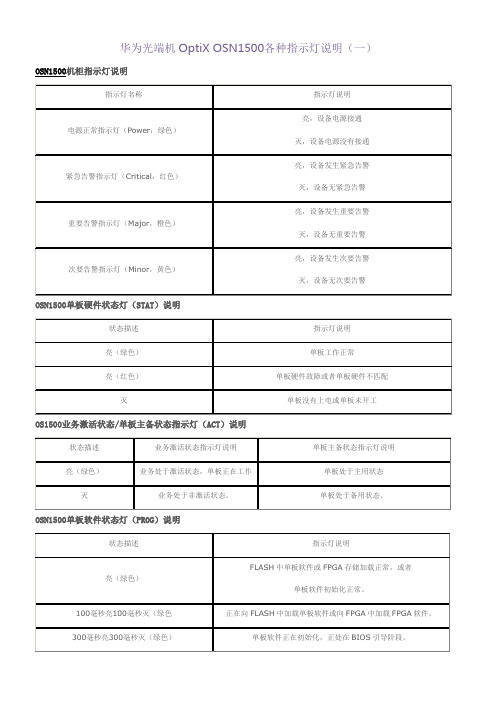
华为光端机OptiX OSN1500各种指示灯说明(一)OSN1500机柜指示灯说明OSN1500单板硬件状态灯(STAT)说明OS1500业务激活状态/单板主备状态指示灯(ACT)说明OSN1500单板软件状态灯(PROG)说明华为OSN1500单板指示灯说明(二)OSN1500业务告警指示灯(SRV)说明单板类型状态描述指示灯说明业务板亮(绿色)业务工作正常,没有任何业务告警产生。
亮(红色)业务有紧急或重要告警。
亮(黄色)业务有次要和远端告警。
灭没有配置业务且没有告警,或没有电源输入。
OSN1500同步时钟状态灯(SYNC)说明状态描述指示灯说明亮(绿色)时钟工作在自由振荡方式,且没有设置系统时钟优先级表(系统时钟优先级表默认只有内部源)。
时钟工作在跟踪模式,并且正在跟踪优先级表中除内部源以外的其他时钟源。
亮(红色)已经设置了系统时钟优先级表,但是除内部源外,表中的其他时钟源都已经丢失,时钟工作在保持模式或者由振荡模式。
OSN1500告警切除指示灯(ALMC)状态描述指示灯说明亮(黄色)当前处在告警长期切除状态灭有告警立刻用声音提示OSN1500以太网指示灯说明指示灯名称状态描述指示灯说明连接状态指示灯-LINK(绿色)亮纤缆与设备连接成功灭纤缆与设备没有连接上数据收发指示灯-ACT(橙色)闪烁有数据收发灭没有数据收发OSN1500交叉连接单元业务激活状态灯(ACTX)说明状态描述指示灯说明亮(绿色)交叉连接单元处于主用状态灭交叉连接单元处于备用状态OSN1500主控单元主备状态指示灯(ACTC)说明状态描述指示灯说明亮(绿色)主控单元处于主用状态灭主控单元处于备用状态华为OSN1500单板指示灯说明(三)OSN1500线路单元业务告警指示灯(SRVL)说明:状态描述指示灯说明亮(绿色)线路业务正常,没有告警产生亮(红色)线路业务有紧急告警或重要告警亮(黄色)线路业务有次要告警或远端告警灭没有配置线路业务且没有告警,或者没有电源输入OSN1500交叉单元业务告警指示灯(SRVX)说明:状态描述指示灯说明亮(绿色)业务工作正常,没有任何业务告警产生亮(红色)发生了业务倒换,如TPS倒换。
Quidway Eudemon 200E-C&200E-F 防火墙 硬件描述(V100R002_01)

1.2.1 产品外观................................................................................................................................................1-2 1.2.2 接口编号方法........................................................................................................................................1-4 1.3 设备参数.........................................................................................................................................................1-5 1.4 环境要求.........................................................................................................................................................1-5 1.4.1 储存环境................................................................................................................................................1-6 1.4.2 运输环境................................................................................................................................................1-8 1.4.3 运行环境..............................................................................................................................................1-10
TD020001EN技术数据手册说明书

ContentsDescriptionP ageGeneral information . . . . . . . . . . . . . . . . . . . . . . . . . . . . . . . . . . . . . . . . . . . . . . . . . . . . . . . . . . . . . . . . .2–3400A starter design . . . . . . . . . . . . . . . . . . . . . . . . . . . . . . . . . . . . . . . . . . . . . . . . . . . . . . . . . . . . . . . . .4–9 800A starter design . . . . . . . . . . . . . . . . . . . . . . . . . . . . . . . . . . . . . . . . . . . . . . . . . . . . . . . . . . . . . . . .10–15 Control and potential transformers . . . . . . . . . . . . . . . . . . . . . . . . . . . . . . . . . . . . . . . . . . . . . . . . . . . . . .16 Current transformers . . . . . . . . . . . . . . . . . . . . . . . . . . . . . . . . . . . . . . . . . . . . . . . . . . . . . . . . . . . . . . . . .17Fuses . . . . . . . . . . . . . . . . . . . . . . . . . . . . . . . . . . . . . . . . . . . . . . . . . . . . . . . . . . . . . . . . . . . . . . . . . .18–21Solid-state reduced voltage . . . . . . . . . . . . . . . . . . . . . . . . . . . . . . . . . . . . . . . . . . . . . . . . . . . . . . . . .22–24Ampgard medium voltagemotor control renewal parts2Technical Data TD020001ENEffective October 2014Ampgard medium voltage motor control renewal partsEATON Ampgard renewal and replacement partsThe present design of Ampgard T medium voltage starters was introduced in 2005 . Additional ratings and features have been continuously introduced over the years .This renewal parts guide will provide the proper identification of standard parts which may be required for the repair or mainte-nance of Eaton Ampgard starters .Style numbers identified in this document may not be the same as style numbers on the original equipment . The renewal part styles in this document may be in a kit form and include subassembly, carton, installation instructions, etc .Identifying your equipmentThe following can help you in identifying which version of Ampgard you have . The current version of Ampgard as shown in the bot-tom illustration on page 3, has the low voltage door/compartment located on the front of the medium voltage unit in a separate iso-lated compartment . In addition, the non-load break switch (isolation switch) is located to the right of the low voltage compartment . The previous style of Ampgard, referred to as Classic Ampgard, has the low voltage compartment to the right of the medium voltage compartment as shown in the top illustration on page 3 . The isolation switch is located on the top of the medium voltage compartment .This document addresses the current generation of Ampgard . For earlier designs, please contact your local Eaton representative . There are numerous variations in Ampgard starters . Most of theparts listed in this guide are included in the more common variations . 400A starters are available with contactors that use bolted or finger connections . Fuses may be clip-in or bolt-in . Contactors are modified for high-altitude (above 2000m) .There are many variations of phase barriers . Common reasons for these variations include the use of special current transformers or other optional equipment, or special provisions for customer cable connections . Dimensions are shown for each of the barriers offered in this guide . Insure that the replacement barriers match the size of those originally supplied . If the original barriers are of a different size, contact Eaton for identification of the correct replacement part numbers .800A contactors were the “SJ” series through March 2014 . The contactors were changed to the “SL ” series beginning April 2014 . The specific parts used in the two contactors are different, but the complete contactor assemblies are interchangeable . Parts detailed in this document will specify if they are for the “SJ” version or the “SL ” version of the contactor . Replacement vacuum interrupters are not available for the “SJ” version . Complete replacement contactors will be the “SL ” series only .Additional serviceShould you experience difficulty in determining needed parts for repair or determining existing starter condition, contact your local Eaton representative . We can provide qualified technical personnel on site to:•Identify and recommend replacement parts for damage caused by short-circuit of fault• Remove damaged parts and install replacements• Retrofit vintage motor-starting equipment with new components • Evaluate condition of existing equipment • Test components• Provide a recommended spare parts list •Upgrade horsepower ratingGeneral Information3Technical Data TD020001ENEffective October 2014Ampgard medium voltage motor control renewal partsEATON Figure 1. Classic AmpgardFigure 2. Current Ampgard (covered in this guide)400A starter Isolation switch LV compartment400A starter800A starterLV compartment Isolation switch4Technical Data TD020001ENEffective October 2014Ampgard medium voltage motor control renewal partsEATONFigure 3. 7.2 kV , 400A, 2-highBolted connectionFigure 4. 400A contactor with bolted connectionFinger connectionFigure 5. 400A contactor with finger connectionVacuum interruptersFigure 6. 400A contactor (bottom view)Control board Auxiliary contacts400A starter design5Technical Data TD020001ENEffective October 2014Ampgard medium voltage motor control renewal partsEATON Figure 7. Stab connectionFigure 8. Bolted connectionTypeStyle number400A bolt-in main contactor (120 Vac, 130 ms dropout a ) b SL72B4SH3LANL7MNR25400A stab-in main contactor (120 Vac, 130 ms dropout a ) b SL72S4SH3LANL7MNR25400A bolt-in reversing contactor (120 Vac, 130 ms dropout a ) b SL72B4SH3LANL7VNR25400A stab-in reversing contactor (120 Vac, 130 ms dropout a ) b SL72S4SH3LANL7VNR25400A bolt-in latched contactor (120 Vac close and trip) b SL72B4SH3LAL45MNR25400A stab-in latched contactor (120 Vac close and trip) bSL72S4SH3LAL45MNR25a Dropout time is field adjustable.bStandard altitude contactor. For high altitude applications (>2000m) contact factory.T able 1. 400A contactors (7.2 kV and below)6Technical Data TD020001ENEffective October 2014Ampgard medium voltage motor control renewal partsEATONType Style number400A 54A1310G02Type Style number400A 54A1310G05Type Style number400A 54A1302G20Type Style number400A 54A1310G01TypeStyle number400A54A1300G20(139.7)(172.7)8.40T able 2. 400A lower fuse phase barriers single barrel fuse (qty. 4)T able 3. 400A fuse phase barriers double barrel fuse (qty. 4)T able 4. 400A contactor load stab barriers (qty. 4)T able 5. 400A motor load phase barriers (qty. 4)T able 6. 400A isolation switch barrier double barrel (qty. 4)7Technical Data TD020001ENEffective October 2014Ampgard medium voltage motor control renewal partsEATON TypeStyle numberBolt-in fuse 54A1301G03 (order barriers separately)Clip-in fuse 54A1301G04 (order barriers separately)TypeStyle number400A SL 54A1302G02 (order barriers separately)TypeStyle numberBolt-in fuse 54A1301G01 (order barriers separately)Clip-in fuse54A1301G02 (order barriers separately)T able 7. 400A contactor line stab and lower fuse-mount assembly for bolt-in contactorT able 8. 400A contactor load stab assembly for bolt-in contactorT able 9. 400A motor load connection assembly (T1, T2, T3)T able 10. 400A contactor line stab and lower fuse-mount assembly for stab-in contactorT able 11. 400A contactor load stab assembly for stab-in contactorType Style number400A load 54A1306G01 (order barriers separately)Type Style number400A SL54A1302G01 (order barriers separately)8Technical Data TD020001ENEffective October 2014Ampgard medium voltage motor control renewal partsEATON T able 14.400A contactor mechanical interlock kitT able 12. 400A vacuum bottle assembly (qty. 3)Type Style number400A SL 2147A58G02T able 13. Auxiliary contact assembly (2NO/2NC)Type Style number400A SL 2147A58G04Type Style numberMain 87C0600G01Reversing 87C0600G02Run or start 87C0600G03T able 15. 400A control circuit board(includes mounting bracket and hardware)Type Style number400A SL 2147A58G03T able 16. 400A dual coil kitType Style number400A SL 2147A58G11T able 17. 400A mechanical latch assemblyType Style number24 Vdc coil and diode 2147A58G2548 Vdc coil and diode2147A58G26125 Vac/Vdc coil and diode 2147A58G27250 Vac/Vdc coil and diode 2147A58G28Mechanical assembly2147A58G249Technical Data TD020001ENEffective October 2014Ampgard medium voltage motor control renewal partsEATON T able 18. 400A isolation switch fixed portionType Style numberIsolation switch fixed portion 54A1300G01T able 19. Handle mechanism(contact factory for kirk key option)Type Style number400A full voltage54A1305G01400A reduced voltage(with two door interlock pins)54A1305G02T able 20. 400A isolation switch removable portionTypeStyle numberBolt-in fuse54A1300G02 (order barriers for double barrel fuses separately)Bolt-in fuse with blown fuse bar 54A1300G03 (order barriers for double barrel fuses separately)Clip-in fuse54A1300G04 (order barriers for double barrel fuses separately)10Technical Data TD020001ENEffective October 2014Ampgard medium voltage motor control renewal partsEATONFigure 9. 7.2 kV 800AL63 contact (economizing)Figure 10. 800A SJ series contactor (front view)Vacuum interruptersFigure 11. 800A SJ series contactor (rear view)Figure 12. 800A SL series contactor (front view)L64 auxiliary contacts800A starter designType Style number800A SL series standard stab-in contactor(120 Vac, 130 ms dropout, interchangeable with SJ series) SL72S8SH3LANL7MNR25800A SL series reversing stab-in contactor(120 Vac, 130 ms dropout, interchangeable with SJ series)SL72S8SH3LANL7VNR25800A SL series latching stab-in contactor(120 Vac close and trip, interchangeable with SJ series)SL72S8SH3LAL45MNR25T able 21. 800A SL series complete replacement contactorsT able 22. 800A lower fuse phase barriers (qty. 4)TypeStyle number800A 54A1310G07T able 23. 800A isolation switch barriers (qty. 4)Type Style number800A 54A1300G20T able 24. 800A motor load connection assembly (T1, T2, T3)Type Style number800A SL 87C0599G01 (order barriers separately)T able 25. 800A motor load phase barriers (qty. 4)Type Style number800A 54A1310G01T able 26. 800A contactor load stab phase barriers (qty. 4)Type Style number800A 54A1302G21T able 27. 800A contactor load stab assemblyType Style number800A SL 87C0598G07 (order barriers separately)8.40T able 28. 800A contactor line stab and lower fuse-mount assemblyTypeStyle number800A SL 87C0597G05 (order barriers separately)T able 29. 800A SJ series magnetic assembly (complete with coil and springs)Type Style number120 Vac 2147A88G02240 Vac 2147A88G03Without coil 2147A88G04T able 30. 800A SJ series L -63 interlock (coil circuit)Type Style numberInterlock 578D461G03Type Style number1NO/1NC 843D943G212NO 843D943G222NC843D943G23T able 32. 800A SJ series contactor dual main coil assemblyType Style number120 Vac 2147A88G11240 Vac 2147A88G12T able 33. 800A contactor mechanical interlock kit (SJ or SL)Type Style numberInterlock kit87C0726G01T able 31. 800A SJ series L -64 auxiliary interlocksT able 34. 800A SL series main coilType Style numberCoil 54A1307G18T able 35. 800A SL series control circuit boardTypeStyle number800A SL 54A1307G24T able 36. 800A SL series line finger assembly (qty. 3)TypeStyle number800A SL 54A1307G20T able 37. 800A SL series auxiliary interlocksType Style number2NO/2NC 54A1307G22T able 38. 800A SL series vacuum bottle assembly (qty. 3)Type Style number800A SL54A1307G19T able 39. 800A SL series load finger assembly (qty. 3)Type Style number800A SL54A1307G13T able 40. 800A isolation switch removable portion (blown fuse indicator (BFI) optional)Type Style numberWithout BFI 54A1300G12 (order barriers separately)With BFI 54A1300G13 (order barriers separately)T able 41. 800A isolation switch fixed portionType Style numberFixed portion 54A1300G11T able 42. Handle mechanism (contact factory for kirk key option)Type Style number800A full voltage54A1305G05T able 43. Standard 750 VA control transformer, 60 HzTypeStyle number2300/120V C7.5A1D1F24160/120V C7.5E1D1F2T able 44. Potential transformer 100 VA three-phase, 60 Hz, open deltaType Style number2400/120V PT3A0F64200/120V PT3E0F6T able 45. Vacuum interrupter wear gaugeType Style number400A (.020)5259C11H01800A (.060)5259C11H02T able 46. 2 kVA control transformer, 60 HzTypeStyle number2300/120V C20A1D1F24160/120V C20E1D1F2T able 47. Ground fault current transformerType Style number50/5 ratio 54A1314G02Control and potential transformersT able 48. Current transformers three-phase donut type with leadsRatio Style number100/554A1303G01150/554A1303G02200/554A1303G03250/554A1303G04300/554A1303G05400/554A1303G06500/554A1303G07600/554A1303G08800/554A1303G091000/554A1303G10T able 49. Current transformers single-phase donut type (qty. 3)Ratio Style number50/5a75/5b100/52147A13G04150/52147A13G05200/52147A13G06250/52147A13G07300/52147A13G08400/52147A13G09500/52147A13G10600/52147A13G11750/52147A13G12800/52147A13G131000/52147A13G141200/52147A13G15a Use style number 2147A13G04 and double loop primary leads.b Use style number 2147A13G05 and double loop primary leads.Current transformersT able 50. Clip-in fuses, 5.0 kV maximum (qty. 3)Type Rating Style numberCLS 400A motor starter30A—1R 2A98253G0170A—2R 2A98253G02100A—3R 2A98253G03130A—4R 2A98253G04150A—5R 2A98253G05170A—6R 2A98253G06200A—9R 2A98253G07230A—12R 2A98253G08390A—18R a 2A98253G09450A—24R a 2A98253G10HLE 400A feeder starter10E 2A98253G4115E 2A98253G4220E 2A98253G4325E 2A98253G4430E 2A98253G4540E 2A98253G4650E 2A98253G4765E 2A98253G4880E 2A98253G49100E 2A98253G50125E 2A98253G51150E 2A98253G52200E 2A98253G53250E 2A98253G55300E a 2A98253G56350E a 2A98253G57400E a 2A98253G58450E a 2A98253G59a Double barrel.FusesT able 51. Clip-in fuses, 7.2/8.3 kV maximum (qty. 3)Type Rating Style number CLS 400A motor starter70A—2R2A98253G21100A—3R2A98253G22130A—4R2A98253G23150A—5R2A98253G24170A—6R2A98253G25200A—9R2A98253G26230A—12R2A98253G27390A—18R a2A98253G28450A—24R a2A98253G29 HLE 400A feeder starter10E2A98253G7115E2A98253G7220E2A98253G7325E2A98253G7430E2A98253G7540E2A98253G7650E2A98253G7765E2A98253G7880E2A98253G79100E2A98253G80125E2A98253G81150E2A98253G82175E2A98253G83200E a2A98253G84250E a2A98253G85300E a2A98253G86350E a2A98253G87 a Double barrel.T able 52. Bolt-in fuses, 5.0 kV maximum (qty. 3)Type Rating Style number CLS 400/800A motor starter30A—1R54A1311G1170A—2R54A1311G12100A—3R54A1311G13130A—4R54A1311G14150A—5R54A1311G15170A—6R54A1311G16200A—9R54A1311G17230A—12R54A1311G18390A—18R a54A1311G19450A—24R a54A1311G20 CLS 800A motor starter650A—36R a54A1311G21800A—44R a54A1311G22 HLE 400/800A feeder starter15E54A1311G4120E54A1311G4225E54A1311G4330E54A1311G4440E54A1311G4550E54A1311G4665E54A1311G4780E54A1311G48100E54A1311G49125E54A1311G50150E54A1311G51175E54A1311G52200E54A1311G53250E54A1311G54300E a54A1311G55350E a54A1311G56400E a54A1311G57450E a54A1311G58 HLE 800A feeder starter600E a54A1311G59750E a54A1311G60 a Double barrel.21EATON T able 53. Bolt-in fuses, 7.2/8.3 kV maximum (qty. 3)Type Rating Style numberCLS 400/800A motor starter100A—3R 54A1312G11130A—4R 54A1312G12150A—5R 54A1312G13170A—6R 54A1312G14200A—9R 54A1312G15230A—12R 54A1312G16390A—18R a 54A1312G17450A—24R a 54A1312G18HLE 400/800A feeder starter15E 54A1312G3520E 54A1312G3625E 54A1312G3730E 54A1312G3840E 54A1312G3950E 54A1312G4065E 54A1312G4180E 54A1312G42100E 54A1312G43125E 54A1312G44150E 54A1312G45180E 54A1312G46200E a 54A1312G47250E a 54A1312G48300E a 54A1312G49350E a 54A1312G50a Double barrel.22EATON 400A MV4S reduced voltage solid-stateDigital control unit 54A1318G01Figure 13. 400A MV4S starter (front view)Figure 14. 400A MV4S starter (doors open)Solid-state reduced voltage23EATON T able 55.400A MV4S control door and control compartmentType Style numberComplete truck assembly 400A/4160V 54A1320G01400A/2300V 54A1320G02400A/3300V 54A1320G03200A/4160V 54A1320G04200A/2300V 54A1320G05200A/3300V54A1320G06Bypass contactor VI assembly (includes line side fingers)54A1307G17Bypass contactor complete54A1319G01Bypass contactor load finger assembly 54A1307G16Power pole assembly (single-phase) 400A/4160V 54A1318G200 400A/2300V 54A1318G201 200A/4160V 54A1318G300 200A/2300V 54A1318G301 Temperature board54A1318G09Type Style numberCommunications harness 54A1318G31T able 54. 400A MV4S solid-state truck assemblyEaton1000 Eaton Boulevard Cleveland, OH 44122United States © 2014 EatonAll Rights Reserved Printed in USAPublication No. TD020001EN / BC-201October 2014Eaton is a registered trademark.All other trademarks are property of their respective owners.T able 56.400A MV4S control compartmentType Style numberFiber optics 4160V 54A1318G22 2300V 54A1318G23 XP34160V 54A1318G24 2300V54A1318G25CPU and MCB 54A1318G02Transformer 54A1318G04CT board 54A1318G08CT harness 54A1318G42TCB board 54A1318G03Fiber optics。
OptiX OSN1500以太网单元介绍

FE1
FE3
FE1
FE2
FE2
FE1
FE4FE3ຫໍສະໝຸດ FE3FE1FE4
FE4
FE2
FE2
FE5
FE5
EFT 4
FE3 FE4
FE5
FE6
FE6
STAT ACT PROG SRV
FE6
FE3
FE7
FE7
FE5
FE1
FE7
FE8
FE8
FE6
FE2
FE4
FE8
CLASS 1 LASER PRODUCT
FE7 FE8
告警含义与原因
单板故障 以太网连接中断 级联的VC3-xc中断 封装协议失配 对端网元发生TU-AIS-VC3 VC-Trunk 带宽减少
主要告警
TU_AIS_VC3 PROTOCOL_MM LP_RDI_VC3
次要告警
LCAS_B或
_DECREASED
以太网单元(续)
性能事件 RX-BYTE-BAD-CNT TX-BYTE-BAD-CNT RX-PKT-65-CNT(65~127) 接收不正确数据包字节数上报 非正常发送字节数上报 接收的65~127字节长度的数据包(含错误的) 具体含义
OUT1 IN1 OUT2 IN2
FE1
基于权重的公平算法和3种业务等级
拓扑自动发现 保护倒换
FE2
GE端口 LC连接器
FE3
Wrap Steering Wrap+steering
FE4
EMR0
EGR2
FE端口 RJ45连接器
以太网单元(续)
告警级别
Eaton MN280070EN 电源系列重闭锁电缆应用电容液指示说明书

Dielectric grease application to recloser cable instructionsDISCLAIMER OF WARRANTIES AND LIMITATION OF LIABILITYThe information, recommendations, descriptions and safety notations in this document are based on Eaton Corporation’s (“Eaton”) experience and judgment and may not cover all contingencies. If further information is required, an Eaton sales office should be consulted. Sale of the product shown in this literature is subject to the terms and conditions outlined in appropriate Eaton selling policies or other contractual agreement between Eaton and the purchaser.THERE ARE NO UNDERSTANDINGS, AGREEMENTS, WARRANTIES, EXPRESSED OR IMPLIED, INCLUDING WARRANTIES OF FITNESS FOR A PARTICULAR PURPOSE OR MERCHANTABILITY, OTHER THAN THOSE SPECIFICALL Y SET OUT IN ANY EXISTING CONTRACT BETWEEN THE PARTIES. ANY SUCH CONTRACT STATES THE ENTIRE OBLIGATION OF EATON. THE CONTENTS OF THIS DOCUMENT SHALL NOT BECOME PART OF OR MODIFY ANY CONTRACT BETWEEN THE PARTIES. In no event will Eaton be responsible to the purchaser or user in contract, in tort (including negligence), strict liability or other-wise for any special, indirect, incidental or consequential damage or loss whatsoever, including but not limited to damage or loss of use of equipment, plant or power system, cost of capital, loss of power, additional expenses in the use of existing power facilities, or claims against the purchaser or user by its customers resulting from the use of the information, recommendations and descriptions contained herein. The information contained in this manual is subject to changewithout notice.iCABLE INSTRUCTIONS MN280070EN May 2017ContentsDISCLAIMER OF WARRANTIES AND LIMITATION OF LIABILITY . . . . . . . . . . . . . . . . . . . . . . . . . . . . . . . . . . . .I SAFETY FOR LIFE . . . . . . . . . . . . . . . . . . . . . . . . . . . . . . . . . . . . . . . . . . . . . . . . . . . . . . . . . . . . . . . . . . . . . . . . .III SAFETY INFORMATION . . . . . . . . . . . . . . . . . . . . . . . . . . . . . . . . . . . . . . . . . . . . . . . . . . . . . . . . . . . . . . . . . . . .III Safety instructions (iii)PRODUCT INFORMATION . . . . . . . . . . . . . . . . . . . . . . . . . . . . . . . . . . . . . . . . . . . . . . . . . . . . . . . . . . . . . . . . . . . .1 Introduction (1)Acceptance and initial inspection (1)Handling and storage (1)Quality standards. . . . . . . . . . . . . . . . . . . . . . . . . . . . . . . . . . . . . . . . . . . . . . . . . . . . . . . . . . . . . . . . . . . . . . . . . . . . . . . .1 Materials and tools required (1)INSPECTION AND CLEANING PROCEDURE . . . . . . . . . . . . . . . . . . . . . . . . . . . . . . . . . . . . . . . . . . . . . . . . . . . . .2 DIELECTRIC GREASE APPLICATION PROCEDURE . . . . . . . . . . . . . . . . . . . . . . . . . . . . . . . . . . . . . . . . . . . . . . . .3ii CABLE INSTRUCTIONS MN280070EN May 2017Eaton’s Cooper Power series products meet or exceed all applicable industry standards relating to product safety. We actively promote safe practices in the use and maintenance of our products through our service literature, instructional training programs, and the continuous efforts of all Eaton employees involved in product design, manufacture, marketing, and service.We strongly urge that you always follow all locally approved safety procedures and safety instructions when working around high voltage lines and equipment, and support our “Safety For Life” mission.CABLE INSTRUCTIONS MN280070EN May 2017Dielectric grease application to recloser cable instructionsProduct informationIntroductionService Information MN280070EN provides factory recommended inspection and cleaning of recloser/control cables and the application instructions for dielectric grease. Refer to the appropriate Service Information for complete installation and maintenance instructions for yourspecific product.●●Service Information MN280060EN, Installation of Types VWE, VWVE27, VWVE38X, WE, WVE27 and WVVE38X●●Service Information S280-40-7, Types RXE and WE Maintenance Instructions●●Service Information MN280061EN, Maintenance of Types VWE and VWVE Reclosers●●Service Information S280-40-4, Maintenance of EarlyWE Reclosers●●Service Information MN280063EN, Installation of Types VSA12, VSA16, VSA20 and VSA20A Reclosers●●Service Information MN280064EN, Maintenance of Types VSA12, VSA16, and VSA20/800 Reclosers●●Service Information S280-45-3, VSML Recloser Maintenance Manual●●Service Information S280-45-2, Maintenance of Early VSA Reclosers●●Service Information S280-42-1, NOVA™ 15, 27 and 38 kV Reclosers Installation and Operation Instructions●●Service Information MN280046EN, Types NOVA STS-15, NOVA STS-27, and NOVA STS-38 Single-Tank, Triple-Single, Electronically Controlled Recloser Installation and Operation Instructions●●Service Information MN280045EN, NOVA-TS 15, 27, and38 Recloser Installation and Operation Instructions●●Service Information MN280048EN, SPEAR™ Single-Phase Recloser System Installation and Operation Instructions●●Service Information MN280049EN, Form 4D Control Installation and Operation Instructions●●Service Information MN280065EN, Type VSO12 and VSO16 Motor-Operated, Electronically Controlled Recloser Operation and Installation Instructions●●Service Information MN280066EN, Maintenance of Type VSO Reclosers●●Service Information S280-70-2, Form 6 Yard Mount Recloser Control Instructions●●Service Information S280-70-3, Form 6 Pole Mount Recloser Control Instructions Read this manual firstRead and understand the contents of this manual and follow all locally approved procedures and safety practices before installing or operating this equipment.Additional informationThese instructions cannot cover all details or vari a tionsin the equipment, procedures, or process described, nor provide directions for meeting every possible contingency during installation, operation, or maintenance. When additional information is desired to satisfy a problem not cov e red sufficiently for the user's purpose, please contact your Eaton representative.Acceptance and initial inspectionCables are thoroughly inspected at the factory. They are in good condition when accepted by the carrier for shipment. Upon receipt of the cables, a thorough inspection should be made for damage, evidence of rough handling, or shortages. Should this initial inspection reveal evidence of rough handling, damage, or shortages, it should be noted on the bill of lading and a freight claim should immediately be made with the carrier. Also, notify your Eaton representative.Handling and storageBe careful during handling and storage of the cable to minimize the possibility of damage. If the cable is to be stored for any length of time prior to installation, provide a clean, dry storage area.Quality standardsISO 9001 Certified Quality Management System.otee:N Any cable (any manufacturer) is subject to the environment; Eaton's Cooper Power series cables areno different. If the cable is not installed properly, apotential for moisture ingress exists and therefore, apotential for corrosion exists.It is recommended practice to train and support cables (e.g., with cable ties, etc.) in such a manner as to relieve the connector of excessive dead weight strain and minimize the effect of wind force on the cable.Materials and tools required●●Small wire brush●●Pipe cleaners●●Disposable cleaning towels●●Electrical insulating compound - AGS® High Energy Dielectric Protector, Dow Corning® 4 electrical insulating compound, or approved equivalent.1CABLE INSTRUCTIONS MN280070EN May 2017Dielectric grease application to recloser cable instructions2CABLE INSTRUCTIONS MN280070EN May 2017Dielectric grease application to recloser cable instructionsDielectric grease application procedure6. If no corrosion is present or after a majority of thecorrosion has been removed, clean and dry the female recloser receptacle and female cable connector. Next, apply 1/16th of an inch of AGS ® High Energy Dielectric Protector, Dow Corning ® 4 electrical insulatingcompound, or approved equivalent (approximately the thickness of a quarter) uniformly across the clean and dried face of the female connector. There is no need to apply dielectric grease to the male recloser receptacle and male cable connector. Dielectric grease willdisplace any moisture from bridging the gap betweenthe pins and prevent corrosion.Figure 4 . Female receptacle with dielectric grease applied otee:N A properly installed cable is fully seated whenconnected such that the O-ring is compressed.7. Insert the cable connector into the receptacle on therecloser. Ensure the keyway lines up properly. 8. Ensure the cable connector is fully mated withthe receptacle. 9. Rotate the cinch ring on the cable connector until thecable connector is fully seated – this means that the cinch ring is turned a full 7 revolutions (approx. 20 turns of the wrist).10. The cinch ring should be hand tightened. When it canbe turned no further by hand, give the plug body a push into the mating receptacle and continue turning the cinch ring. Continue this process until the cinch ring will turn no further by hand and the plug body cannot bepushed any further into the mating receptacle.plug body can be pushed in and out of the receptacle, the connector is likely cross-threaded . In this condition, the connection seal is compromised . This condition must be corrected or equipment damage may result . T380 .011. Repeat the same procedure for the control and junctionbox (if present).12. Verify the recloser and control operation by openingand closing the recloser several times via the front panel buttons on the control. Verify the open and close status lights on the control correspond to the state of the recloser.13. The recloser is ready to put into service.Figure 5 . Visual aid for application of dielectric grease .3CABLE INSTRUCTIONS MN280070EN May 2017Eaton1000 Eaton Boulevard Cleveland, OH 44122United StatesEaton’s Power Systems Division 2300 Badger Drive Waukesha, WI 53188United States/cooperpowerseries© 2017 EatonAll Rights ReservedPrinted in USAPublication No. MN280070EN May 2017Eaton is a registered trademark.All trademarks are propertyof their respective owners.For Eaton’s Cooper Power series productinformationcall 1-877-277-4636 or visit:/cooperpowerseries.。
电子元器件基础知识

2、作用:通低频,阻高频,滤波,消除高频交流
成份 ;
3、单位换算:
1H=103 mH(毫亨)=106 uH(微亨);
4、其它:色环电感…
制造事业部
电子元器件基础知识
四、变压器
1、代号“T”—英文TRANSFORMER 缩写;
2、单位换算:同电感;
3、作用:变压、升压、降压;
4、主要特性:体积大,笨重,
SOP器件又称为SOIC(Small Outline Integrated Circuit)
是DIP的缩小形式,引线中心距为1.27mm,引脚形
式:欧翼型、J型、I型,常用欧翼型。
制造事业部
电子元器件基础知识
十三、集成电路——封装
塑封有引线芯片载体PLCC(Plastic Leaded Chip Carrier)
方形扁平封装QFP,主要应用于ASIC(Application Of
Specific Integrated Circuit)专用集成电路。普通引线
中心距为1.0mm、0.8mm、0.65mm、0.5mm,目前亦
有采用0.3mmQFP。为保证引出线良好的共面性,美 国的QFP器件四个脚都有一个突出的脚,其尺寸超 过引出线O.05mm。
制造事业部
电子元器件基础知识
二、电容——金属化聚酯薄膜电容器
1、C/POLYEST :有安规要求,外表通常呈黃、
灰、紫色;
2、作用:跨电源线,无线电干扰抑制器,天线耦合
3、容值范围:0.01 uF ~2.2 uF
制造事业部
电子元器件基础知识
三、电感
1、代号为“L”、“LF”——LINE FILTER –EI.UU.EE
电压不稳定
CFMA 电气培训

MC20电气培训1.840DSL系统组成及硬件连接。
2.H ELLER 电气原理图。
3.机床及操作介绍。
4.诊断与维修。
5.840DSL系统及数据管理。
第一节840DSL系统组成及硬件连接1.系统连接示意图系统网络:以太网(绿色)连接->TCU、MCP、HT8、……等部件驱动系统网络:DRIVE-CLiQ网络(绿色)连接->SINAMICS S120驱动系统部件PLC IO网络:Profi Bus网络(紫色)连接->ET200M、ET200S、ET200Pro……等IO模块2.系统连接接口图3.MC20选用的NCU及NX模块MC20选用的NCU为NCU730.2/PN,其特点是:自带P L C CPU319,DRIVE-LINK 接口为6个,最大控制轴数为31轴,10个通道,本机床用2个通道,本机床配一个TCU。
X X100-X105 DRIVE-CLiQ 接口X122/X132 输入/输出I/O接口X124 24V电源输入X120 以太网(系统网络)X130 以太网(工厂网络)X126 Profi bus-DP1X136 Profi bus-DP2/MPIX125/X135 USB接口X131-X134 DAC测量端子X109 CF 卡插槽X127 以太网(服务接口)X190 双风扇/电池模块Option slot RS232模块或NCU Link模块下图标出了NCU 操作和显示元件,这些元件对接通和启动SINUMERIK 840D sl 有着重要作用。
• LED 灯:各种故障和状态• 7 段显示:NCU运行状态显示•复位键:NCU硬件复位,相当于系统断电,重启。
• NCK 开机调试开关(左):NCK总清• PLC 运行方式开关(右):PLC总清• CF 插槽:系统软件卡在第一次PLC 开机调试时,在接通和启动NCU 后必须进行一次PLC 总清。
为了达到一个初始的系统(NCK 和PLC)输出状态,此时也必须清除NCK数据。