装修后多久才能入住?没想到98%的人都做错了
普通话考试备考资料:难点字音记忆方法
普通话难点音主要集中于平翘舌音、鼻边音以及前后鼻音等,这些难点音字数较多,怎样在掌握这些难点音发音方法的基础上,采用便捷的方法记住相对应的汉字,从而让普通话的学习更加轻松而事半功倍呢?下面按照不同的声、韵母,将容易混淆的汉字进行对比,提供记忆的方法和字表。
一、平、翘舌音汉字的记忆(一)记忆方法第一,利用形声字声旁类推。
一般来说,声旁相同的形声字,声母往往相同。
例如,具有“支zhī”声旁的汉字“枝、吱、吱、肢、汥”等都是翘舌音字,具有“司sī”声旁的汉字“伺、饲、嗣”等都是平舌音字。
我们可以利用声旁类推或者声旁代表字类推的方法记住平翘舌音汉字。
当然不排除特殊情况,例如,具有“叟sǒu”声旁的汉字“搜、艘、嗖、馊、飕”等是平舌音字,但“瘦”则读翘舌音“shòu”;具有“师shī”声旁的汉字“狮、筛”等是翘舌音字,但“蛳”则读平舌音“sī”。
不过这种情况非常少,我们在记忆的时候,可将特别读音单列,单独记忆。
(见附表一:zh和z、ch和c、sh和s代表字类推表)第二,利用普通话声韵拼合规律类推。
普通话声韵拼合是有一定规律的,例如,韵母“uang、uai、ua”只能跟翘舌音zh、ch、sh相拼,不能跟平舌音z、c、s相拼,因此“装、拽、抓、窗、踹、爽、帅、刷”等汉字一定是翘舌音字;韵母“ong”只能跟平舌音s相拼,不能跟翘舌音sh相拼,因此“松、嵩、耸、送、宋、诵”等汉字一定是平舌音字。
(见附表二:zh和z、ch和c、sh和s的对比辨音字表)第三,利用记少不记多的方法。
汉字中平舌音的字少,而翘舌音字多,约为平舌音字的两倍。
可以记住少量的平舌音字,来确定多数的翘舌音字。
例如,音节“sen”的汉字仅有一个字“森”,而音节“shen”的汉字则有“申、、深、身、沈、什、肾、渗、慎、哂、莘、蜃、娠”等;音节“ca”的汉字只有“擦、嚓”两个汉字,而音节“cha”的汉字则有“差、查、茶、插、叉、察、岔、茬、刹、诧”等。
成语及其词意解释

五笔词语解释aaaa恭恭敬敬:【释义】(1)对长辈贵宾谦恭而有礼貌。
(2)对别人很有礼貌、很尊敬。
用法:作定语、状语;用于处世。
相近词:毕恭毕敬。
相反词:不可一世。
aaal 花花世界:【解释】:指繁华的、吃喝玩乐的地方。
也泛指人世间。
【出自】:宋·文及翁《贺新郎·西湖》词:“回首洛阳花世界,烟渺黍离之地。
”【示例】:史见满园青翠萦目,红紫迎人,真是锦绣乾坤,~。
◎清·李汝珍《镜花缘》第四回。
【近义词】:灯红酒绿。
【语法】:偏正式;作宾语、定语;含贬义,指花天酒地的场所aaay劳苦功高:解释】:出了很多力,吃了很多苦,立下了很大的功劳。
【出自】:《史记·项羽本纪》:“劳苦而功高如此。
”【示例】:这是决战的最后五分钟了!这一班~的“英雄”,手颤颤地举着“胜利之杯”,心头还不免有些怔忡不定。
◎茅盾《子夜》十五。
【近义词】:功德无量、公垂竹帛【反义词】:劳而无功、徒劳无益。
【语法】:联合式;作谓语、定语;含褒义aabg 草草了事:【解释】:草草:形容草率、马虎;了:办完,结束。
草率地把事情结束了。
【出自】:明·朱国桢《涌幢小品·实录》:“陈文端请修正史,分各志二十八,务于详备,一志多至四五十万余言。
未几,文端薨,各志草草了事。
”【示例】:虽说僧经道忏,吊祭供饭,络绎不绝,终是钱银吝啬,谁肯踊跃,不过~。
◎清·曹雪芹《红楼梦》第一百一十回。
【近义词】:草草收兵、敷衍了事【反义词】:一丝不苟、兢兢业业【语法】:偏正式;作谓语、分句;含贬义,指做事马马虎虎。
aabu 茕茕孑立qióng qióng jié lì:【解释】:孤身一人。
形容一个人无依无靠,孤苦伶仃。
【出自】:晋·李密《陈情表》:“外无期功强近之亲,内无应门五尺之童。
茕茕孑立,形影相吊。
”【示例】:我凑着~的小油灯,尽情享受秋灯夜读的乐趣。
蓬组词三年级第一单元小练笔作文

蓬组词三年级第一单元小练笔作文《我的好朋友》
我的好朋友叫小花,她有一双大大的眼睛,笑起来像弯弯的月亮。
小花特别喜欢画画。
每次上美术课,她总是第一个拿出画笔,认真地画起来。
她画的花朵五颜六色,就像真的在风中跳舞一样。
有一次,我们一起参加学校的绘画比赛,她画了一幅美丽的花园,还得了一等奖呢!
小花还是个很善良的人。
有一次我摔倒了,膝盖擦破了皮,疼得我眼泪都快出来了。
小花看到后,马上跑过来扶起我,还轻轻地帮我吹伤口,安慰我说:“别怕,一会儿就不疼啦。
”
我喜欢我的好朋友小花,希望我们能永远一起玩耍,一起学习,一起长大!
《春天来了》
春天来啦!春风轻轻地吹着,就像妈妈的手抚摸着我的脸,暖暖的,柔柔的。
公园里的花开了,有红的、粉的、黄的,五颜六色,好看极了!蝴蝶在花丛中飞来飞去,好像在跳舞。
小草从地下探出了脑袋,嫩绿嫩绿的,充满了生机。
小河里的冰融化了,河水哗哗地流淌着,好像在唱着欢快的歌。
河边的柳树长出了嫩绿的叶子,长长的柳枝在风中摇摆,就像小姑娘的辫子。
小朋友们也都出来玩耍啦!有的在放风筝,有的在骑自行车,还有的在捉迷藏,大家玩得可开心了!
春天真是个美丽又有趣的季节!。
EM828164PA-60资料

128M: 8M x 16 Mobile SDRAM Document Title128M: 8M x 16 Mobile SDRAMRevision HistoryRevision No. Date History0.0Jun 4, 2007 Initial Draft0.1Nov 8, 2007 - Table9 Operating AC Parameter updated for setup & hold time- Table9 Operating AC Parameter updated for tWR- Table2 Bonding Pad Location and Identification table deleted- Signal names unified to /CK, /CS, /RAS, /CAS, /WE respectively(Ex.) CK#, CK, CKB unified to /CK- Release date for Revision 0.0 corrected- IDD6 value in Table 6 & Table 13 modifiedEmerging Memory & Logic Solutions Inc.4F Korea Construction Financial CooperationB/D, 301-1 Yeon-Dong, Jeju-Do, Korea Zip Code : 690-717 Tel : +82-64-740-1700 Fax : +82-64-740-1750 / Homepage : The attached datasheets provided by EMLSI reserve the right to change the specifications and products. EMLSI will answer to your questions about device. If you have any questions, please contact the EMLSI office.128M: 8M x 16 Mobile SDRAM128M : 8M x 16bit Mobile SDRAM Table 1: ORDERING INFORMATIONNOTE :1. EMLSI are not designed or manufactured for use in a device or system that is used under circumstance in which human life is potentially at stake.Please contact to the memory marketing team in emlsi electronics when considering the use of a product contained herein for any specific purpose, such as medical, aerospace, nuclear, military, vehicular or undersea repeater use.Part No.Max Freq.Interface PackageEM828164PA-60166 (CL3), 111 (CL2)LVCMOS Wafer Biz.EM828164PA-75133 (CL3), 83 (CL2)EM828164PA-90111 (CL3), 66 (CL2)FEATURES· 1.8V power supply.·LVCMOS compatible with multiplexed address. · Four banks operation.· MRS cycle with address key programs. · CAS latency (1, 2 & 3).·Burst length (1, 2, 4, 8 & Full page). · Burst type (Sequential & Interleave).· All inputs are sampled at the positive going edge of the system clock.· Burst read single-bit write operation. ·EMRS cycle with address key programs. · PASR(Partial Array Self Refresh). · DS (Driver Strength) · Internal auto TCSR(Temperature Compensated Self Refresh) · Deep power-down(DPD) mode. ·DQM for masking. ·Auto refresh.·64ms refresh period (4K cycle).·Extended Temperature Operation (-25 ~ 85 ).GENERAL DESCRIPTIONThis EM series is 134,217,728 bits synchronous high data rate Dynamic RAM organized as 4 x 2,098,152 words by 16bits, fabri-cated with EMLSI’s high performance CMOS technology. Syn-chronous design allows precise cycle control with the use of system clock and I/O transactions are possible on every clock cycle. Range of operating frequencies, programmable burst lengths and programmable latencies allow the same device to be useful for a variety of high bandwidth and high performance mem-ory system applications.128M: 8M x 16 Mobile SDRAMTable 2: Pad DescriptionSymbol Type DescriptionsCLK Input Clock : CLK is driven by the system clock. All SDRAM input signals are sampled on the positive edge of CLK. CLK also increments the internal burst counter and controls the output registers.CKE Input Clock Enable : CKE activates(HIGH) and deactivates(LOW) the CLK signal. Deactivating the clock provides PRECHARGE POWER-DOWN and SELF REFRESH operation(all banks idle), ACTIVE POWER-DOWN(row ACTIVE in any bank), DEEP POWER-DOWN (all banks idle), or CLOCK SUS-PEND operation(burst/access in progress). CKE is synchronous except after the device enters power-down and self refresh modes, where CKE becomes asynchronous until after exiting the same mode. The input buffers, including CLK, are disabled during power-down and self refresh modes, providing low standby power. CKE may be tied HIGH./CS Input Chip Select : /CS enables (registered LOW) and disables (registered HIGH) the command decoder. All commands are masked when /CS is registered HIGH. /CS provides for external bank selection on sys-tems with multiple banks. /CS is considered part of the command code./RAS, /CAS, /WE Input Command Inputs: /CAS, /RAS, and /WE(along with /CS) define the command being entered.LDQM, UDQM Input Input/Output Mask : DQM is sampled HIGH and is an input mask signal for write accesses and an out-put enable signal for read accesses. Input data is masked during a WRITE cycle. The output buffers are placed in a High-Z state (two-clock latency) during a READ cycle. LDQM corresponds to DQ0-DQ7, UDQM corresponds to DQ8-DQ15. LDQM and UDQM are considered same state when refer-enced as DQM.BA0, BA1 Input Bank Address Input(s): BA0 and BA1 define to which bank an ACTIVE, READ, WRITE or PRE-CHARGE command is being applied. These balls also select between the mode register and the extended mode register.A0 - A11 Input Address Inputs: A0-A11 are sampled during the ACTIVE command(row address A0-A11) and READ/ WRITE command(column-address A0-A8; with A10 defining auto precharge) to select one location out of the memory array in the respective bank. A10 is sampled during a PRECHARGE command to deter-mine if all banks are to be precharged(A10 HIGH) or bank selected by BA0, BA1(LOW). The address inputs also provide the op-code during a LOAD MODE REGISTER command.DQ0-DQ15 I/O Data Bus: Input / Output VDD Supply Power SupplyVSS Supply GroundVDDQ Supply I/O Power Supply VSSQ Supply I/O Ground128M: 8M x 16 Mobile SDRAMDevice OperationSimplified State DiagramPower OnDeep Power DownPrecharge All BanksIdle All banks prechargedSelf RefreshMRS EMRSAuto RefreshPrecharge Power DownActive Power DownRow ActiveBurst StopWRITEWRITE APrecharge PREALLREAD AREADPower appliedDPDSXMRSDPDSACTREFABSTREADREADAWRITEAPRE REFSXREFSCKEL CKEHCKELCKEH WRITEREADREADA READAPREPREPREWRITEA Automatic Sequence Command SequenceACT = ActiveBST = Burst Terminate CKEL = Enter Power-Down CKEH =Exit Power-Down DPDS = Enter Deep Power-Down DPDSX = Exit Deep Power-DownEMRS = Ext. Mode Reg. Set MRS = Mode Register Set PRE = PrechargePREALL = Precharge All Banks REFA = Auto Refresh REFS = Enter Self RefreshREFSX = Exit Self Refresh READ = Read w/o Auto Precharge READA = Read with Auto Precharge WRITE = Write w/o Auto Precharge WRITEA = Write with Auto PrechargeREADWRITEWRITEWRITEABurst StopBST128M: 8M x 16 Mobile SDRAMFUNCTIONAL BLOCK DIAGRAMADDRESS DECODERBANK CONTROL DATA ROW -ADDRESS DECODERCOLUMN -DM MASK LOGIC I/O GATING SENSE AMPLIFIERSLOGICREFRESH COUNTEROUTPUT REGISTERA0 - A11BA0, BA1CKE CLK/CS /RAS /CAS /WESTANDARD MODEREGISTER EXTENDED MODEREGISTERCOMMAND DECODECONTROL LOGIC4,09651214DQ0 -DQ15LDQM UDQMx 4x 4x 416922 1212162A D D R E S S R E G I S T E R141616READ DATA LATCH WRITE DRIVERS216DATA INPUT REGISTERx 4BANK MEMORYARRAY (4,096 x 512 x 16)128M: 8M x 16 Mobile SDRAMElectrical SpecificationsTable 3: ABSOLUTE MAXIMUM RATINGSNOTE :Permanent device damage may occur if ABSOLUTE MAXIMUM RATINGS are exceeded.Functional operation should be restricted to recommended operating condition.Exposure to higher than recommended voltage for extended periods of time could affect device reliability.Table 4: DC OPERATING CONDITIONSRecommended operating conditions (Voltage referenced to V SS = 0V, T A = -25o C~ 85o C for Extended)NOTE :1. Under all conditions, VDDQ must be less than or equal to VDD.2. VIH (max) = 2.2V AC. The overshoot voltage duration is 3ns.3. VIL (min) = -0.1V AC. The undershoot voltage duration is 3ns.4. Any input 0V VIN VDDQInput leakage currents include Hi-Z output leakage for all bi-directional buffers with tri-state outputs.5. Dout is disabled, 0V VOUT VDDQ.Table 5: CAPACITANCE (V DD = 1.8V, T A = 23 , f=1 , Vref = 0.9V 50mV)ParameterSymbol Value Unit Voltage on any pin relative to V SSV IN ,V OUT -0.5 ~ 2.5V Voltage on V DD and V DDQ supply relative to V SS V DD , V DDQ-0.5 ~ 2.5VStorage temperature T STG -55 ~ +150Power dissipation P D 1.0W Short circuit current I OS50ParameterSymbol Min Typ Max Unit Note Supply voltageV DD1.7 1.8 1.95V 1V DDQ1.7 1.8 1.95V 1Input logic high voltage V IH 0.8 x V DDQ1.8V DDQ + 0.3V 2Input logic low voltage V IL -0.300.3V 3Output logic high voltage V OH 0.9 x V DDQ--V I OH = -0.1mA Output logic low voltage V OL --0.1 x V DDQV I OL = 0.1mAInput leakage current I LI-2-24PinSymbol Min Max Unit NoteClockC CLK 1.5 3.5 /RAS, /CAS, /WE, /CS, CKE, DQM C IN 1.5 3.0 Address C AD0 1.5 3.0 DQ 0 ~ DQ 15C OUT2.04.5128M: 8M x 16 Mobile SDRAMTable 6: DC CHARACTERISRICSRecommended operating conditions (Voltage referenced to V SS = 0V, T A = -25o C~ 85o C for Extended)NOTE :1. It has 5 tolerance.2. Refresh period is 64ms.3. Internal TCSR can be supported.In extended Temp : 45°C/Max 85°C4. DPD (Deep Power Down) function is an optional feature and it will be enabled upon request. Please contact EMLSI for more information.5. Unless otherwise noted, input swing level is CMOS (VIH/VIL=VDDQ/VSSQ)ParameterSymbolTest ConditionVersionUnit-60-75-90Operating Current (One Bank Active)I DD1Burst length = 1tRC tRC(min)Io = 0mA504035mAPrecharge Standby Cur-rent in power-down modeI DD2P CKE VIL(max), tcc =10ns 0.3mAI DD2PS CKE & CLK VIL(max), tcc =0.3Precharge Standby Cur-rent in non power-down modeI DD2N CKE VIH(min), /CS VIH(min), tcc = 10ns Input signals are changed one time during 20ns 10mAI DD2NS CKE VIH(min), CLK VIL(max), tcc = Input signals are stable 1Active Standby Current in power-down modeI DD3P CKE VIL(max), tcc = 10ns 5mAI DD3PS CKE & CLK VIL(max), tcc =1Active Standby Current in non power-down mode (One Bank Active)I DD3N CKE VIH(min), /CS VIH(min), tcc = 10ns Input signals are changed one time during 20ns 20mAI DD3NSCKE VIH(min), CLK VIL(max), tcc = Input signals are stable 10mA Operationg Current (Burst Mode)I DD4Io = 0mA Page burst4banks activated tCCD = 2clks 808045mAmARefresh Current I DD5tRFC tRFC(min)909085mA Self Refresh CurrentI DD6CKE 0.2vTCSR Range45*185°CFull Array 120200µA1/2 of Full Array 1201601/4 of Full Array100140Deep Power Down Current I DD8CKE 0.2v 10µA128M: 8M x 16 Mobile SDRAMTable 7: AC OPERATING TEST CONDITIONS(V DD = 1.7V ~ 1.95V, T A = -25o C~ 85o C for Extended)ParameterValueUnit NoteAC input levels(Vih/Vil)0.8 V DDQ / 0.2 V DDQV Input timing measurement reference level 0.5 V DDQV Input rise and fall time1.0V/ns Output timing measurement reference level 0.5 V DDQ VOutput load conditionSee Figure 21.8V13.9V OH (DC) = 0.9 x V DDQ , I OH = -0.1V OL DDQ , I OL = 0.1 20Z0=50Vtt=0.5 V DDQ 5020Figure 1. DC Output Load CircuitFigure 2. AC Output Load CircuitOutputOutput10.6128M: 8M x 16 Mobile SDRAMTable 8: OPERATING AC PARAMETER(AC operating conditions unless otherwise noted)Parameter Sym-bol-60-75-90Unit Note Min Max Min Max Min MaxDQ output access time from CLK t AC 5.4 5.47.0ns1,2 Clock high-level width t CH0.450.550.450.550.450.55t CK3 Clock low-level width t CL0.450.550.450.550.450.55t CK3Clock half period t HPmin(t CL,t CH)min(t CL,t CH)min(t CL,t CH)nsClock cycle time CL = 3t CK67.59ns1 CL = 291215nsDQ input setup time t DS 2.5 2.5 2.5nsDQ input hold time t DH 1.0 1.0 1.0ns Address input setup time t AS 2.5 2.5 2.5ns3 Address input hold time t AH 1.0 1.0 1.0ns3 DQ low-impedance time from CLK t LZ 1.0 1.0 1.0ns2 DQ high-impedance time from CLK t HZ 6.0 6.07.0ns MODE REGISTER SET command period t MRD222t CKCKE hold time t CKH111nsCKE setup time t CKS 1.5 1.5 2.5ns/CS, /RAS, /CAS, /WE, DQM hold time t CMH 1.0 1.0 1.0ns/CS, /RAS, /CAS, /WE, DQM setup time t CMS 2.5 2.5 2.5nsData-out hold time t OH 2.5 2.5 2.5ns2 ACTIVE to PRECHARGE command period t RAS50100,00050100,00050100,000ns4 ACTIVE to ACTIVE command period t RC72.572.574ns4 AUTO REFRESH toACTIVE / AUTO REFRESH command periodt RFC808090ns7 ACTIVE to READ or WRITE delay t RCD22.522.524ns4 PRECHARGE command period t RP1822.524ns4 ACTIVE bank A to ACTIVE bank b delay t RRD222t CK4 READ/WRITE command to READ/WRITE command t CCD111t CK WRITE recovery time t WR151515ns5 Auto precharge write recovery + precharge time t DAL t WR+t RP t WR+t RP t WR+t RPSelf refresh exit to next valid command delay t XSR90112.5120nsExit power down to next valid command delay t XP t CK+t CKS t CK+t CKS t CK+t CKS128M: 8M x 16 Mobile SDRAM NOTE :1. Parameters depend on programmed CAS latency.2. If clock rising time is longer than 1ns, (tr/2-0.5)ns should be added to the parameter.3. Assumed input rise and fall time (tr & tf) = 1ns.If tr & tf is longer than 1ns, transient time compensation should be considered.i.e.,[(tr + tf)/2-1]ns should be added to the parameter.4. The minimum number of clock cycles is determined by dividing the minimum time required with clock cycle time and then rounding off to the nexthigher integer.5. Minimum delay is required to completed write.6. Maximum burst refresh cycle : 87. All parts allow every cycle column address change.Functional DescriptionIn general, the 128Mb SDRAMs (2 Meg x 16 x 4 banks) are quad-bank DRAMs that operate at 1.8V and include a syn-chronous interface (all signals are registered on the positive edge of the clock signal, CLK). Each of the x16’s 33,554,432-bit banks is organized as 4,096 rows by 512 columns by 16 bits.Read and write accesses to the SDRAM are burst oriented; accesses start at a selected location and continue for a programmed number of locations in a programmed sequence. Accesses begin with the registration of an ACTIVE command, which is then followed by a READ or WRITE command. The address bits registered coincident with the ACTIVE command are used to select the bank and row to be accessed (BA0 and BA1 select the bank, A0-A11 select the row). The address bits (A0-A8) registered coincident with the READ or WRITE command are used to select the starting column location for the burst access.Prior to normal operation, the SDRAM must be initialized. The following sections provide detailed information covering device initialization, register definition, command descriptions and device operation.InitializationSDRAMs must be powered up and initialized in a predefined manner. Operational procedures other than those speci-fied may result in undefined operation. Power should be applied to VDD and VDDQ simultaneously. Once the power is applied to VDD and VDDQ, and the clock is stable (stable clock is defined as a signal cycling within timing constraints specified for the clock pin), the SDRAM requires a 100µs delay prior to issuing any command other than a DESELECT or NOP. Starting at some point during this 100µs period and continuing at least through the end of this period, DESE-LECT or NOP commands should be applied.Once the 100µs delay has been satisfied with at least one DESELECT or NOP command having been applied, a PRE-CHARGE command should be applied. All banks must then be precharged, thereby placing the device in the all banks idle state.Once in the idle state, two AUTO refresh cycles must be performed. After the AUTO refresh cycles are complete, the SDRAM is ready for mode register programming. Because the mode register will power up in an unknown state, it should be loaded prior to applying any operational command.128M: 8M x 16 Mobile SDRAM Mode Register DefinitionIn order to achieve low power consumption, there are two mode registers in the mobile component, mode register and extended mode register. The mode register defines the specific mode of operation of the SDRAM, including burst length, burst type, CAS latency, operating mode, and write burst mode. The mode register is programmed via the LOAD MODE REGISTER command and will retain the stored information until it is programmed again or the device loses power.Mode register bits A0-A2 specify the burst length, A3 specifies the type of burst (sequential or interleaved), A4-A6 specify the CAS latency, A7 and A8 specify the operating mode, A9 specifies the write burst mode. A10 and A11 should be set to zero. BA0 and BA1 should be set to zero to prevent extended mode register.The mode register must be loaded when all banks are idle, and the controller must wait the specified time before initi-ating the subsequent operation. Violating either of these requirements will result in unspecified operation.Burst LengthRead and write accesses to the SDRAM are burst oriented, with the burst length being programmable. The burst length determines the maximum number of column locations that can be accessed for a given READ or WRITE com-mand. Burst lengths of 1, 2, 4, or 8 locations are available for both the sequential and the interleaved burst types, and a full-page burst is available for the sequential type. The full-page burst is used in conjunction with the BURST TERMI-NATE command to generate arbitrary burst lengths. Reserved states should not be used, as unknown operation or incompatibility with future versions may result. When a READ or WRITE command is issued, a block of columns equal to the burst length is effectively selected. All accesses for that burst take place within this block, meaning that the burst will wrap within the block if a boundary is reached.Burst TypeAccesses within a given burst may be programmed to be either sequential or interleaved; this is referred to as the burst type and is selected via bit A3.The ordering of accesses within a burst is determined by the burst length, the burst type, and the starting column address.CAS LatencyThe CAS latency is the delay, in clock cycles, between the registration of a READ command and the availability of the first piece of output data. The latency can be set to one, two, or three clocks.If a READ command is registered at clock edge n, and the latency is m clocks, the data will be available by clock edge n + m. The DQs will start driving as a result of the clock edge one cycle earlier (n + m - 1), and provided that the rele-vant access times are met, the data will be valid by clock edge n + m.Reserved states should not be used as unknown operation or incompatibility with future versions may result. Operating ModeThe normal operating mode is selected by setting A7 and A8 to zero; the other combinations of values for A7 and A8 are reserved for future use and/or test modes. The programmed burst length applies to both read and write bursts. Test modes and reserved states should not be used because unknown operation or incompatibility with future versions may result.Write Burst ModeWhen A9 = 0, the burst length programmed via A0-A2 applies to both READ and WRITE bursts; when A9 = 1, the pro-grammed burst length applies to READ bursts, but write accesses are single-location (nonburst) accesses.128M: 8M x 16 Mobile SDRAMExtended Mode RegisterThe extended mode register controls functions specific to low power operation. These additional functions include drive strength, temperature compensated self refresh, and partial array self refresh.This device has default values for the extended mode register (if not programmed, the device will operate with the default values . PASR = Full Array, DS = Full Drive).Temperature Compensated Self RefreshOn this version of the Mobile SDRAM, a temperature sensor is implemented for automatic control of the self refresh oscillator on the device. Programming of the temperature compensated self refresh (TCSR) bits will have no effect on the device. The self refresh oscillator will continue refresh at the factory programmed optimal rate for the device tem-perature.Partial Array Self RefreshFor further power savings during SELF REFRESH, the PASR feature allows the controller to select the amount of memory that will be refreshed during SELF REFRESH. Low Power SDRAM supports 3 kinds of PASR in self refresh mode : Full Array, 1/2 of Full Array and 1/4 of Full ArrayOutput Driver StrengthBecause the Mobile SDRAM is designed for use in smaller systems that are mostly point to point, an option to control the drive strength of the output buffers is available. Drive strength should be selected based on the expected loading of the memory bus. Bits A5 and A6 of the extended mode register can be used to select the driver strength of the DQ out-puts.BA1=0BA0=0BA0=1BA1=0BA1=0BA1=0BA0=0BA1=1BA1=1BA0=0BA0=1- Full Array- 1/2 Array- 1/4 ArrayPartial Self Refresh AreaBA1=1BA1=1BA1=0BA1=0BA0=0BA0=1BA1=1BA0=1BA0=0BA0=0BA0=1BA1=1BA0=1128M: 8M x 16 Mobile SDRAMTable 9: Mode Register Field Table to Program modesRegister Programmed with Normal MRS NOTE :1. RFU(Reserved for future use) should stay “0” during MRS cycle.Table 10: Normal ModeNOTE :1. MRS can be issued only at all bank precharge state.2. Minimum tRP is required to issue MRS command.Address BA0 ~ BA1A11 ~ A10/APA9A8A7A6A5A4A3A2A1A0Function "0" Setting for Normal MRSRFU *1W.B.LOperating ModeCAS LatencyBTBurst LengthOperating Mode CAS Latency Burst TypeBurst Length A8A7TypeA6A5A4Latency A3Type A2A1A0BT=0BT=100Mode Register Set000Reserved0Sequential 0001101Reserved 00111Interleave 0012210Reserved 0102Mode Select 0104411Reserved0113BA1BA0Mode01188Write Burst Length 100Reserved 0Setting for Normal MRS100Reserved Reserved A9Length101Reserved101Reserved Reserved 0Burst 110Reserved 110Reserved Reserved 1Single Bit111Reserved111Full PageReserved128M: 8M x 16 Mobile SDRAMTable 11: Register Programmed with Extended MRSNOTE :1. RFU(Reserved for future use) should stay “0” during MRS and EMRS cycle.Table 12: EMRS for PASR(Partial Array Self Refresh) & DS(Driver Strength)Address BA1BA0 A11 ~ A10/AP A9A8A7A6A5A4A3A2A1A0Function Mode SelectRFU *1DSRFU *1PASRMode SelectDriver Strength PASRBA1BA0MODE A6A5Driver Strength A2A1A0Size of Refreshed Array00Normal MRS 00Full 000Full Array 01Reserved 011/20011/2 of Full Array 10EMRS for SDRAM101/40101/4 of Full Array 11Reserved111/8011Reserved Reserved Address100Reserved A11~A10/APA9A8A7A4A3101Reserved 011Reserved111Reserved128M: 8M x 16 Mobile SDRAMTable 13: Internal Temperature Compensated Self Refresh (TCSR)NOTE :1. In order to save power consumption, Low power SDRAM includes the internal temperature sensor and control units to control the self refresh cycle automatically according to the two temperature range : Max 85 , Max 452. If the EMRS for external TCSR is issued by the controller, this EMRS code for TCRS is ignored.3. It has +/- 5 tolerance.BURST SEQUENCETable 14: BURST LENGTH = 2Table 15: BURST LENGTH = 4Table 16: BURST LENGTH = 8Temperature RangeSelf Refresh Current (Icc 6)UnitFull Array1/2 of Full Array1/4 of Full ArrayMax 85 200160140Max 45120120100Initial AddressSequentialInterleaveA000101111Initial AddressSequentialInterleaveA1A000012301230112301032102301230111312321Initial AddressSequentialInterleaveA2A1A0000012345670123456700112345670103254760102345670123016745011345670123210765410045670123456701231015670123454761032110670123456745230111171234567654321128M: 8M x 16 Mobile SDRAM CommandsDESELECTThe DESELECT function(/CS HIGH) prevents new commands from being executed by the SDRAM, regardless of whether the CLK signal is enabled. The SDRAM is effectively deselected. Operations already in progress are not affected.NO OPERATION (NOP)The NO OPERATION (NOP) command is used to perform a NOP to an SDRAM which is selected (/CS is LOW ). This prevents unwanted commands from being registered during idle or wait states. Operations already in progress are not affected.LOAD MODE REGISTERThe mode register is loaded via inputs A0-A11, BA0, BA1. The LOAD MODE REGISTER and LOAD EXTENDED MODE REGISTER commands can only be issued when all banks are idle, and a subsequent executable command cannot be issued until tMRD is met.The values of the mode register and extended mode register will be retained even when exiting deep power-down.ACTIVEThe ACTIVE command is used to open (or activate) a row in a particular bank for a subsequent access. The value on the BA0, BA1 inputs selects the bank, and the address provided on inputs A0-A11 selects the row. This row remains active (or open) for accesses until a PRECHARGE command is issued to that bank. A PRECHARGE command must be issued before opening a different row in the same bank.READThe READ command is used to initiate a burst read access to an active row. The value on the BA0, BA1 inputs selects the bank, and the address provided on inputs A0-A8 selects the starting column location. The value on input A10 determines whether or not auto precharge is used. If auto precharge is selected, the row being accessed will be pre-charged at the end of the READ burst; if auto precharge is not selected, the row will remain open for subsequent accesses. Read data appears on the DQ subject to the logic level on the DQM inputs 2 clocks earlier. If a given DQM signal was registered HIGH, the corresponding DQ will be High-Z two clocks later; if the DQM signal was registered LOW, the DQ will provide valid data.WRITEThe WRITE command is used to initiate a burst write access to an active row. The value on the BA0, BA1 inputs selects the bank, and the address provided on inputs A0-A8 selects the starting column location. The value on input A10 determines whether or not auto precharge is used. If auto precharge is selected, the row being accessed will be precharged at the end of the WRITE burst; if auto precharge is not selected, the row will remain open for subsequent accesses. Input data appearing on the DQs is written to the memory array subject to the DQM input logic level appear-ing coincident with the data. If a given DQM signal is registered LOW, the corresponding data will be written to mem-ory; if the DQM signal is registered HIGH, the corresponding data inputs will be ignored, and a WRITE will not be executed to that byte/column location.PRECHARGEThe PRECHARGE command is used to deactivate the open row in a particular bank or the open row in all banks. The bank(s) will be available for a subsequent row access a specified time (tRP) after the PRECHARGE command is issued. Input A10 determines whether one or all banks are to be precharged, and in the CASe where only 1 bank is to be precharged, inputs BA0, BA1 select the bank. Otherwise BA0, BA1 are treated as “Don’t Care.” Once a bank has been precharged, it is in the idle state and must be activated prior to any READ or WRITE commands being issued to that bank.128M: 8M x 16 Mobile SDRAMAUTO PRECHARGEAUTO PRECHARGE is a feature which performs the same individual-bank precharge function described above, with-out requiring an explicit command. This is accomplished by using A10 to enable auto precharge in conjunction with a specific READ or WRITE command. A precharge of the bank/row that is addressed with the READ or WRITE com-mand is automatically performed upon completion of the READ or WRITE burst, except in the full-page burst mode,where auto precharge does not apply. Auto precharge is nonpersistent in that it is either enabled or disabled for each individual READ or WRITE command.AUTO PRECHARGE ensures that the precharge is initiated at the earliest valid stage within a burst. The user must not issue another command to the same bank until the precharge time (tRP) is completed. This is determined as if an explicit PRECHARGE command was issued at the earliest possible time.BURST TERMINATEThe BURST TERMINATE command is used to truncate either fixed-length or full-page bursts. The most recently regis-tered READ or WRITE command prior to the BURST TERMINATE command will be truncated.AUTO REFRESHAUTO REFRESH is used during normal operation of the SDRAM and is analogous to /CAS BEFORE-/RAS (CBR)refresh in conventional DRAMs. This command is nonpersistent, so it must be issued each time a refresh is required.All active banks must be PRECHARGED prior to issuing an AUTO REFRESH command. The AUTO REFRESH com-mand should not be issued until the minimum tRP has been met after the PRECHARGE command .The addressing is generated by the internal refresh controller. This makes the address bits “Don’t Care” during an AUTO REFRESH command. The 128Mb SDRAM requires 4,096 AUTO REFRESH cycles every 64ms (tREF). Provid-ing a distributed AUTO REFRESH command every 15.625µs will meet the refresh requirement and ensure that each row is refreshed. Alternatively, 4,096 AUTO REFRESH commands can be issued in a burst at the minimum cycle rate (tRFC), once every 64ms.PRECKCommandCKE = HighAutoRefreshCMDt RP t RFCAuto Refresh。
普通话声母训练

(2)组词对比: z-zh 杂质 载重 增长 总帐 奏章 阻止 诅咒
罪证 尊重 佐证 遵照 做主 作者 组织 zh—z 张嘴 种族 长子 沼泽 振作 争嘴 正字
指责 治罪 著作 铸造 壮族 准则 知足 c—ch 财产 操场 采茶 彩绸 餐车 残春 残喘
2.对比辨音: 公费——工会 翻腾——欢腾 附助——互助 发红——花红 放荡——晃荡 防风——黄蜂 飞鱼——黑鱼 浮面——湖面 老房——老黄 芬芳——昏黄 流犯——流汗 西服——西湖
流外,其他情况和g完全一样。
可靠kě kào 困苦kùn kǔ
慷慨kāng kǎi
苛刻kē kè
空旷kōng kuàng 开垦kāi kěn
h 舌根、清、擦音。 发音时,舌根接近软腭,形成窄缝,软腭
上升堵鼻腔通道,声带不颤动,让气流从舌根和软腭之间的窄缝中
挤出,发出磨擦成声。
黄河huáng hé 辉煌huī huáng 互惠hù huì
一、普通话声母基本训练
根据发音部位和发音方法,我们对普通话的21个声母逐个加以 综合说明:
b 双唇、不送气、清、塞音。发音时,双唇自然闭拢,软腭上
升,堵塞鼻腔通道,声带不颤动,让较弱的气流突然冲开双唇的阻
碍,迸发而出,爆破成声。
把柄 bǎ bǐng
爸爸bǎ ba 步兵bù bīng
标榜biāo bǎo 卑鄙bēi bǐ 褒贬bāo biǎn
荷花hé huā
憨厚hān hòu
绘画huì huà
j 舌面、不送气、清、塞擦音。发音时舌面前部抵住硬腭前部
,软腭上升,堵住鼻腔通路,声带不颤动,然后把舌面放松一点儿,让
蓬蘽的食用开发利用栽培可行性研究
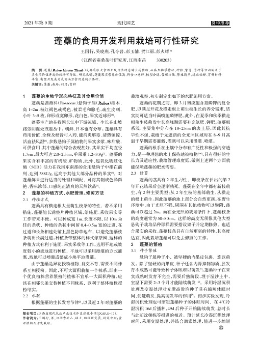
2021年第9期现代园艺蓬蘽的食用开发利用栽培可行性研究王国行,吴晓燕,孔令普,彭玉辅,贺江丽,彭火辉*(江西省蚕桑茶叶研究所,江西南昌330203)摘要:蓬蘽(.)是具有很大食用开发价值的悬钩子属植物,从其生物学特征、种植、繁育、育种等方面阐述了其食用价值开发的栽培可行性。
研究表明,蓬蘽果实营养价值高、鲜食口感好,株型合适、管理方便、繁殖简单、适应性好、育种材料丰富,有望开发成为我国南方食用悬钩子品种。
关键词:蓬蘽;栽培;利用;育种栽培观察,初步制定出如下的水肥施用方案。
蓬蘽的花期之前,即3月初应施含氮磷钾的复合肥,以满足开花及横走根上萌生枝生长的养分需求,结实期可适当叶面喷施磷钾肥。
此外,在夏季和秋季横走根萌生枝萌发生长高峰期需要补充氮肥、钾肥。
蓬蘽根系浅,主要集中分布在10~25cm 的表土层,因此其抗旱性不强,栽植于无遮荫的全光照区域时在8~9月高温干旱期需要灌溉,灌溉可以采用漫灌、喷灌。
蓬蘽的根系在土壤中分布有广泛性和极强的穿透力,是一种理想的水土保持地被植物[5-6],具有很好的生长力及适应性,栽培管理难度低,做到上述两个方面就能保障蓬蘽的肥水需要。
2.3修剪蓬蘽的茎具有2年生习性,即枝条在长出的第2年开花结果后会逐渐枯死。
蓬蘽在全年中都有新枝萌生,有2种主要类型:从2年生枝的基部萌生,从横走的根上萌生。
因此蓬蘽的地上部分会自然更新。
在野生环境中,由于光照不强,周围有其他植物可以攀附,蓬蘽可以超过2m 。
而在全光照的栽培条件下,蓬蘽枝条的高度通常为50~80cm ,这样的高度无须像其他大型悬钩子栽培品种那样需要搭设架子并定期修剪,也适合果实的采收。
蓬蘽枝条具有自然更新的特性,其高度适宜,因此栽培蓬蘽可以免去修剪的工作。
3蓬蘽的繁殖3.1种子繁殖悬钩子属种子小,被坚硬的内果皮包裹,难以萌发。
除了坚硬的内果皮,种子还含内源抑制物质,胚发育不成熟可能导致种子休眠难以萌发[7]。
蓬蘽种子在果实成熟时发育不完全,需要后熟阶段,埋于湿沙土中,室温下需要2~3个月才能陆续萌发[2]。
2018西师大版二年级下册识字二 有故事的成语教案反思作业题

2018西师大版二年级下册识字二有故事的成语教案反思作业题璇嗗瓧浜??1.?8涓銆侀椈銆佹坊銆佸厖銆佹姇鈥?0?2.炬枃閲岀殑10ц嚧浜嗚В晠浜嬨€?3.В锛屼粠??1.?2.????2 璇炬椂銆??竴璇炬椂?1.В?2.鎶€鑳界洰鏍囷細姝g‘銆佹祦鍒╁湴鏈?3.鎯呮劅?鏁欏В???1.勬晠浜嬨€?.2.???1.灏忔湅鍙嬶紝ㄧ敾銆?2.??1.灏?2.甯堢?3.?4.灏忕粍鍚堜綔鎺㈢┒锛氾紙姣忓皬?鐨勬牱瀛愮殑锛熸淳浠h〃璇翠竴璇淬€?5.鍋氳瘑瀛楁父鎴忥細灏嗗瓧濞冨▋璐存垚涓€搴у?棰嗕細鎰熸偀銆?1.?2.?3.鎴戜細鐚?鍥涖€佹嫇灞曞欢浼搞€?1.?2.?1锛庢垜浼氬~銆?d 菐n d脿j墨ng c菐i ti谩n k貌ng ti膩n ji膩f霉q墨n ________ ________ ________ ________ ________ 闄勭瓟妗堬細鑳嗗ぇ绮惧僵娣诲姞鐖朵翰2锛庢垜鑳藉垎寰楁竻銆?绮撅紙锛?鎶曪紙锛?娣伙紙锛?闂伙紙锛?鎯咃紙锛?璁撅紙锛?鑸旓紙锛?锛?闄勭瓟妗堬細?鎶曪紙鎶曞叆锛?娣伙紙娣诲姞锛??鎯咃紙鐖辨儏锛?璁撅紙璁?鑸旓紙鑸斾竴鑸旓級?3?锛?锛夊崼锛?锛夋捣鍗ц柂灏濓紙锛?锛?锛?锛夐浮璧疯垶銆?澶革紙锛夐€愶紙锛?鐢昏泧锛?锛夎冻婊ョ?锛夋暟鎰氾紙锛夌Щ灞?闄勭瓟妗堬細锛堢簿锛夊崼锛堝~锛夋捣鍗ц柂灏濓紙鑳嗭級锛堥椈锛夐浮璧疯垶銆?澶革紙鐖讹級閫愭棩鐢昏泧锛堟坊锛夎冻厖锛夋暟?1.嬪強鎰忔€濄€?2.?3.鎯?敓瀛楋紝杩涗?殑鎰忔€??1.€?2.€佺敓瀛楀崱鐗囥€??1.妭璇炬墍瀛︾敓瀛椼€?2.?銆?В 1.浠旂粏璇绘墖娈点€傦級2.?3.鑰佸笀璁茶Вф佸~骞冲ぇ娴风殑鎰忓織鍜屽媷姘斿€煎緱鎴戜滑瀛︿範銆傛棫鏃舵瘮鍠讳粐?鈶″уぇ灞憋紝浠栫殑鎷愭潠鍙樻垚浜嗕竴鐗囨爲?Щ灞憋細鎰氬叕鍜屼粬鐨勫у淳绁炰粰鎶婇偅涓ゅ骇灞辩Щ璧颁簡銆傛瘮鍠诲潥鎸佷笉鎳堝湴鏀归€犺嚜鐒跺拰鍧氬畾涓嶇Щ鍦拌繘琛屾枟浜夈€??鈶ゆ偓姊佸埡鑲★細姣斿柣寰堝埢鑻︼紝寰堝姫鍔涖€?夊織鎶ュ浗鐨勪汉鍙婃椂濂嬭捣銆?€戦€氳繃璁茶В鏁呬簨锛屼娇瀛︾敓鐞嗚В?涓夈€佸湀鍑虹敓瀛楋紝瀛︿範鍐欏瓧 1.?2.鑰?3.瀛︾敓鍦?6椤典功涓婄敯瀛楁牸閲屾?4.妫€鏌ユ帉鎻℃儏鍐点€?锛?锛夊皬缁勮繘琛屾瘮璧涳紝鐪嬭皝鍐欏緱鍙堝揩鍙堝ソ銆?锛?锛夋姇褰卞睍绀恒€佽瘎浠凤紝鍐嶄慨鏀广€?傚療鑼冨瓧锛屽苟鑳界煡閬撹嚜宸辩殑涓村啓銆傚湪璇勪环鍜屼慨鏀逛腑瀹炵?鍥涖€佹嫇灞曞欢浼?1.甯堬細鑰佸笀杩欓噷杩樻湁鏇寸簿褰╃殑鍥剧墖閫佺粰澶ус€?锛堝笀2.呬簨涔︺€??鎷旇嫍鍔╅暱鍙跺叕濂介緳浜曞簳涔嬭洐鎸囬箍涓洪┈??璇惧爞浣滀笟鏂伙紝杩炵嚎锛屽啀鍐欎竴鍐欍€?j墨ng sh茅n ti谩n xi臎sh墨fu d脿d菐n 澶ц儐甯堢埗闄勭瓟妗堬細j墨ng sh茅n ti谩n xi臎sh墨fu d脿d菐n澶ц儐甯堢埗浜屻€佺収鏍峰瓙鎹㈠亸鏃佹垚鏂板瓧锛岃瘯缁勮瘝銆??璁?鑲?鎶?鎶曞叆_____ ___________ _______________ 闂?鑳?_____ ___________ _____ __________闄勭瓟妗堬細闂?鑲?鑲氬瓙闂?鑳?闂?娌夐椃鑴?鑴变笅涓夈€佺湅?1.鎰氬叕绉诲北锛?锛?A. 姣斿柣鍧氭寔涓嶆噲鍦版敼閫犺嚜鐒跺拰鍧氬畾涓嶇Щ鍦拌繘琛屾枟浜夈€?B.紝鎷氬懡鍦拌拷璧跺お闃炽€?2.锛?A. 杩欎釜鎴愯鐣欎笅缁堣韩閬楁喚銆?B. 灏辨槸璁╁厰瀛愪笂鏍戜笂鍘汇€?3.鍒昏垷姹傚墤锛?锛?A. 灏辨槸鍦ㄨ埞涓婂埢涓婁竴鎶婂墤銆?B. 杩欎釜鏁呬簨鍛婅瘔鎴戜滑彉鍖栫殑闇€瑕併€?闄勭瓟妗堬細 1.A 2.A 3.B ?鏈夋晠浜嬬殑璇惧悗鍙嶆€濓細鐢璺冦€?瑙e喅浜嗕細璁ょ殑瀛椼€?涓夈€佺劧鍚庤€佸笀鍑虹ず鐢熷瓧鍗$墖锛岃繘殑璇婚煶銆佸瓧褰㈢粨鏋勬湁浜嗕簡瑙o紱鍙堥€氳繃瀛︾敓灏忕粍鐩存帴鐨勭珵璧涳紝瀛︾敓鎯呯华婵€鏄傘€傛笎娓愭帉鎻℃湰璇惧瓧璇嶃€?鍥涖€佽В?鐨勫瓧Щ?佹晠浜嬬幆鑺傜粨鏉熷悗锛屾暀甯堝強鏃跺嚭绀哄皬榛戞澘锛屽苟绀鸿寖鍦ㄧ敯瀛楁牸鍐欑敓瀛楋紝瀛︾敓浠垮啓銆?涓冦€侀€氳繃鍋氶殢鍫傜粌涔狅紝宸?濂姐€?。
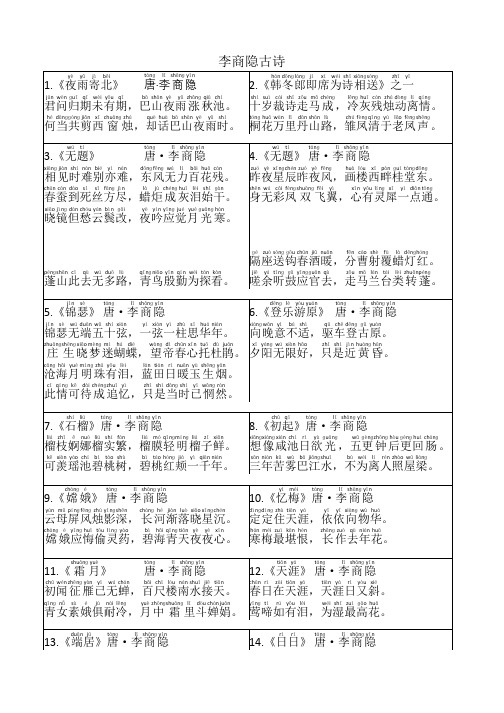
李商隐古诗必背16首(一二年级)
chūn cán dào sǐ sī fānɡ jìn
là jù chénɡ huī lèi shǐ ɡàn
春蚕到死丝方尽,蜡炬 成 灰泪始干。
xiǎo jìnɡ dàn chóu yún bìn ɡǎi
yè yín yīnɡ jué yuè ɡuānɡ hán
晓镜但愁云鬓改,夜吟应觉月 光 寒。
xī yánɡ wú xiàn hǎo
zhǐ shì jìn huánɡ hūn
庄 生 晓梦迷蝴蝶,望帝春心托杜鹃。 夕阳无限好,只是近 黄 昏。
cānɡ hǎi yuè mínɡ zhū yǒu lèi
lán tián rì nuǎn yù shēnɡ yān
沧海月明珠有泪,蓝田日暖玉 生 烟。
cǐ qínɡ kě dài chénɡzhuī yì
身无彩凤 双 飞翼,心有灵犀一点通。
pénɡshān cǐ qù wú duō lù
qīnɡ niǎo yīn qín wéi tàn kàn
蓬山此去无多路,青鸟殷勤为探看。
ɡé zuò sònɡ ɡōu chūn jiǔ nuǎn fēn cáo shè fù là dēnɡhónɡ
隔座送钩春酒暖,分曹射覆蜡灯红。
远书归梦两悠悠,只有空 床 敌素秋。
jiē xià qīnɡ tái yǔ hónɡ shù
yǔ zhōnɡ liáo luò yuè zhōnɡchóu
阶下青苔与红树,雨 中 寥落月 中 愁。
rì rì chūnɡuānɡ dòu rì ɡuānɡ shānchénɡ xié lù xìnɡ huā xiānɡ
何当共剪西 窗 烛,却话巴山夜雨时。
hán dōnɡ lánɡ jí xí wéi shī xiānɡsònɡ zhī yī
- 1、下载文档前请自行甄别文档内容的完整性,平台不提供额外的编辑、内容补充、找答案等附加服务。
- 2、"仅部分预览"的文档,不可在线预览部分如存在完整性等问题,可反馈申请退款(可完整预览的文档不适用该条件!)。
- 3、如文档侵犯您的权益,请联系客服反馈,我们会尽快为您处理(人工客服工作时间:9:00-18:30)。
装修后多久才能入住?没想到98%的人都做错了新房一装修完
大家就恨不得马上拎包入住了
但是你知道在住新房之前的注意事项吗
为全家人的健康
我们还是要了解一下哦
在装修的过程中
都会用上油漆、涂料、木板、胶合板等材料
这些材料多多少少都含有
氨气、甲醛、乙烯等有害气体
虽然过了段时间
异味消失
但装修材料内还是残留少许有害气体
如果不及时处理好
这对人体健康可是有大大的危害
新装修的房子多久可以入住
通风时间至少要在5-6个月以上
有人会有疑问
为什么要这么久
这是因为新装修后的屋子
会存在很多甲醛等气体
一旦吸入过多
会给人体健康带来伤害。