1-API 682 2nd Ed -- Pres 1 EAA Introduction cust
瑞萨E8a使用手册(中文)

2010年4月1日 瑞萨电子公司
【发行】瑞萨电子公司() 【业务咨询】/inquiry
Notice
1. All information included in this document is current as of the date this document is issued. Such information, however, is subject to change without any prior notice. Before purchasing or using any Renesas Electronics products listed herein, please confirm the latest product information with a Renesas Electronics sales office. Also, please pay regular and careful attention to additional and different information to be disclosed by Renesas Electronics such as that disclosed through our website.
6. Renesas Electronics has used reasonable care in preparing the information included in this document, but Renesas Electronics does not warrant that such information is error free. Renesas Electronics assumes no liability whatsoever for any damages incurred by you resulting from errors in or omissions from the information included herein.
KSZ8851-16MLL DEMO BOARD 48-PIN ETHERNET CONTROLLE

SD13
SD7 40
CPU_D14 3
6
SD14
SD8 39
CPU_D15 4
5
SD15
SD9 36
SD10 35
33
SD11 34
CPU_CMD
33
SD12 33
R10
SD13 32
CPU_CSN
33
SD14 31
R12
SD15 30
CPU_WRN
33
CMD
11
R14
CPU_RDN
33
CSN
12
R16
5 6 7 8
TANT
C27
R28 10uF
470pF 2.49K
Power 3.3V 0.1uF (red LED)
CSN CMD
4.7K R27 4.7K R29
GBLC03C_0 D3
GND 2 GND
VR 5 3.3VA
INTRN 4.7K R30
VOUT = 1.24 X [ 1 + ( 2.49k/ 1.5K ) ]
5
4
3
KSZ8851-16MLL (48-pin) Demo Board Black Diagram
D
Headers 20x2
RJ45
LAN1 T
KSZ8851-16MLL
Reset
Power
+1.8V
+2.5V
+3.3V
STATUS LEDs
OSC
EEPROM
C
MIC5209YM
25 MHz
AT93C46
x2
2
1
DATE:
EM63 MID商品说明书
Disclaimer1Thanks very much for purchasing our MID product! Before using this product, please read the manual carefully.We will consider that you have read this manual when you use this product.2. The functions information of this manual is subject to the product itself; we will keep developing new functions. The information in this manual is subject to change without any prior notice.3. The Company will not be responsible for any loss of personal data and damage caused by incorrect operation of software/h ardware, artificial damages, replacement of batteries or any other accident. To avoid loss of your data, please backup your data to your computer at any time.4. We can not control any dispute from users misunderstanding orincorrect operation against the manual, the c ompany will not take any relevant responsibility for any accidental loss potentially occurring in the process of using this manual.5. Please do not repair it by yourself, otherwise, we will not provide you with aftersale service.6.Our c ompany reserves the final explanation right to this manual and other relevant informationPrefaceDear Customers,Thanks very much for purchasing our product! This device is built-in high performance Wifi receiver module, supporting external 3G USB DONGLE wireless network card, turning on the broadband wireless networks, breaking through the restraint of network cable; it will bring you into the portable media player world and fulfill your entertainment needs. It also support picture browsing, E-book Reader, games, online chat and other functions, various settings will fully show your individuality.Safety noticesThis manual contains important information, in order to avoid accidents, please read this manual carefully before you use this product.● Please do not let the player fall or rub or compact with hard objects during using, or it may cause surface scratch of the player,battery loose, data lose or damages of other hardware.. 1 Overview1.1 Appearance and Keys 1.2 Basic Operation 1.2.1 Switch ON 1.2.2 Unlock the Screen 1.2.3 Lock the screen 1.2.4 Switch OFF 1111222Contents1.2.5 Battery charging 1.2.6 Switch input methods 1.2.7 Use T-Flash card1.2.8 Connected to the computer 1.2.9 Browse the file in the device 1.2.10 Startup programs 1.2.11 Close programs 1.2.12 Screen operation 1.2.13 Home screen 1.2.14 Screen gestures 1.2.15 Security setting 1.2.16 Display setting233445555678101.2.17 Wireless And Network Settings 1.3 Technical specifications Warranty811indicating lamp of the device is in high light blue color, the desktop icon of the battery keep rolling which shows it is connected to the device.Press , then it will pop Input Method switch interface.Select the input method you want here.[Noted] After newly install input method, you should choose Settings>Language & input>K e yboard & I n put m ethods then you can use.Please press and drag the icon to the , then the LCD will 1.2.3 Lock the screenWhen the device is in the ON mode, press the POWE R k ey shortly, the system will lock the screen and enter the save power mode. Then the screen is OFF but the system will still un.1.2.4 Switch OFFWhen the device is in the ON mode, press and hold thePOWE R k ey for 3 seconds, the screen will display the power off interface, choose the power off item to confirm, the system will shut automatically.51.2.10 Startup programsClick all the application icon you want to start and it canswitch on.1.2.11Close programsPress the icon continuously or the ESC key, the device willclose the active program. You can also use the correspondingfunction in the management currently running applicationsto close the program.1.2.12 Screen operation● Zoom in and zoom out : In applications which support zoom gestures, such as photo , IE browser, mail and map etc. you can zoom in or out the screen contents by opening or closing your two fingers.● Rolling: In applications which support rolling gestures, such as photo , IE browser, mail and map etc. you can scroll the screen contents by sliding your fingers on the screen. If you want to stop the rolling screen, you just need to touch it.1.2.13 Home screen● Switch home screenIn the home state, you can change the home interface byapplied in one direction.2. Do not remove the TF card before Un i nstalling it, or the card may be damaged.3. If the memory card is write-protected, data will not be formatted and written, please remove the write protection before such operations4. Major brands memory card is recommended to avoid the card is not compatible to this device.5. please well note that the APK (such as application software and games) is default installed to the device. (not the memory card)1.2.8 Connected to the computerOne end of the USB line connect to the computer, the other end connect the MID device, select Settings>Developer options>USB debugging, the device will connect with computer, and you can copy files to the device.41.2.9 Browse the file in the device7If use the pattern, as below:1. You must ensure the four-point connection when you draw the unlock pattern.6s liding your fingers on the screen quickly.● Custom Home ScreenPress the blank area on the home screen interface for a few seconds, it will appear Choose wallpaper from menu, then you can set the home screen.● Move application icons o n screenPress the icons of applications you need to move for several seconds, it will enter the moving model (the icon ofapplication will be turn big), then drag the icon to e xpected position directly.● Move application icons screen to screenPress the icons of applications you need to move for several seconds, and you can drag the icon to the left side or right side.● Delete applicationsPress the icon of application you need to remove for several seconds, drag the icon to × (when the icon turn s big, the bottom of screen will appear ×, then you can delete the application.1.2.14 Screen gestures● ClickWhen you need to input by the on-screen keyboard, you just need to select applications or press the button on the screen, then click the items.● PressWhen you want to start the available options of a project(such as web page link), you only need to press the project.● SlideSliding on the interface with your fingers to make vertical or horizontal dragging action.● DragBefore you start dragging, you must press the items with your fingers, and can not let fingers leave the screen before dragging to the e xpected position.● RotationChanging the screen orientation by rotating the devicelaterally .1.2.15 Security SettingYou can set the unlock pattern , each time you openorwakeyour MID device,you must draw pattern to unlock the screen.in Settings>Security>Screenlock,it support many unlock ways.1.2.16 Display settingClick Settings>Display, you can set the brightness/wallpaper/Auto rotate screen/sleep/font size of the screen.1.2.17 Wireless And Network Settingsa) WIFIClick Settings>Wi-Fi, turn on the wifi, the device will findavailable wireless network n the right interface.o 982. Click Continue and draw again to confirm it3. Cilck confirm to complete unlock pattern designing.4. Each time you open or waking your MID device, you must draw pattern to unlock the screen.Select the expected wireless network, the system will directly connect the network or popup the password input window according to network access security settings. Please consult your wireless network administrator for the password.。
APC Back-UPS Pro 1500VA 865W 230V 10x IEC C13 出口 可
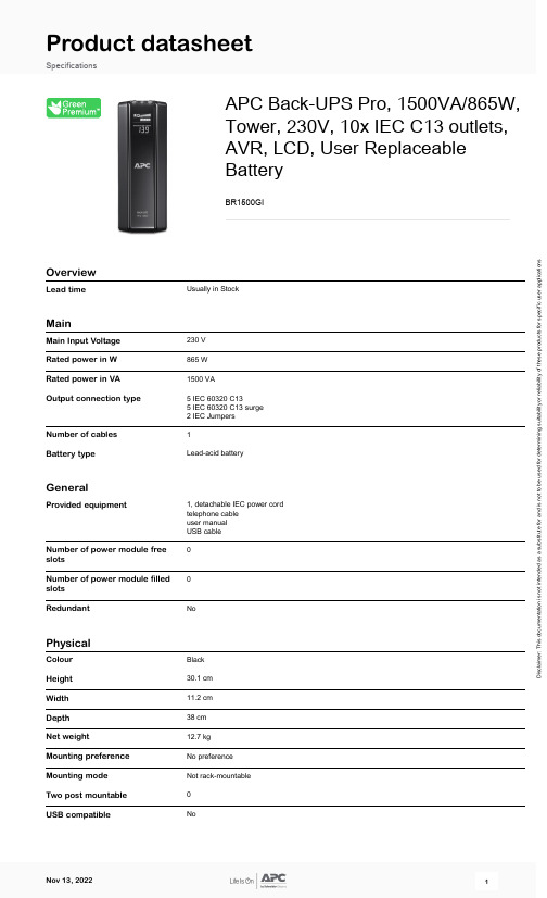
Product datasheetSpecificationsAPC Back-UPS Pro, 1500VA/865W,Tower, 230V, 10x IEC C13 outlets,AVR, LCD, User Replaceable BatteryBR1500GIOverviewLead timeUsually in StockMainMain Input Voltage 230 V Rated power in W 865 W Rated power in VA 1500 VAOutput connection type5 IEC 60320 C135 IEC 60320 C13 surge 2 IEC Jumpers Number of cables 1Battery typeLead-acid batteryGeneralProvided equipment1, detachable IEC power cord telephone cable user manual USB cable Number of power module free slotsNumber of power module filled slots 0RedundantNoPhysicalColour Black Height 30.1 cm Width 11.2 cm Depth 38 cm Net weight12.7 kg Mounting preference No preference Mounting mode Not rack-mountable Two post mountable 0USB compatibleNoD i s c l a i m e r : T h i s d o c u m e n t a t i o n i s n o t i n t e n d e d a s a s u b s t i t u t e f o r a n d i s n o t t o b e u s e d f o r d e t e r m i n i n g s u i t a b i l i t y o r r e l i a b i l i t y o f t h e s e p r o d u c t s f o r s p e c i f i c u s e r a p p l i c a t i o n sInputNetwork frequency50/60 Hz +/- 3 Hz auto-sensingInput voltage limits156...300 V adjustable176...294 VSwitching current capacity10 AOutputMaximum configurable power in865 WWOutput frequency50/60 Hz +/- 3 Hz sync to mains Crest factor 3 : 1UPS type Line interactiveWave type Stepped approximation to a sinewave Maximum configurable power in1500 VAVATransfer time10 ms typical : 12 ms maximum ConformanceProduct certifications A-TickC-TickCEGOSTTelepermitTÜVMarking GS MarkStandards EN/IEC 62040-1:2019/A11:2021EN/IEC 62040-2:2006/AC:2006EN/IEC 62040-2:2018Equipment protection policy Lifetime : 200000 AUDLifetime : 150000 eurosLifetime : 75000 GBP EnvironmentalAmbient air temperature for0…40 °CoperationRelative humidity0…95 %Operating altitude0...30000 ftAmbient air temperature for-15…45 °CstorageStorage Relative Humidity0…95 %Storage altitude0.00…15240.00 mAcoustic level45 dBABatteries & RuntimeNumber of battery filled slots0Number of battery free slots0Battery recharge time8 hNumber of battery replacement1quantityBattery voltage24 VBattery capacity9.0 AhBattery charger power23 W ratedBattery power in VAH216 VAh capacity187 VAh runtimeBattery life3…5 year(s)Replacement battery APCRBC124Battery option BR24BP 1 518 VAhBR24BPG 1 518 VAhBattery graph comments This graph is based on actual measured runtime data. All measurements were taken with new, fullycharged batteries and a balanced resistive load (PF = 1.0). Actual runtimes may vary from the values ofthis graph. Actual runtimes are dependent on several vExtended runtime0Communications & ManagementControl panel Multifunction LCD status and control consoleAlarm Alarm when on battery : distinctive low battery alarm : overload continuous tone alarmSurge Protection and FilteringSurge energy rate441 JNoise suppression Full time multi-pole noise filtering : 10% of IEEE surge let-through : zero clamping response time:instantaneousData line protection RJ11 analog phone line for phone/fax/modem/DSLRJ45 network line - 10/100/1000 Base-T EthernetPacking UnitsUnit Type of Package 1PCENumber of Units in Package 11Package 1 Height38.7 cmPackage 1 Width23.8 cmPackage 1 Length48.8 cmPackage 1 Weight14.3 kgUnit Type of Package 2PALNumber of Units in Package 224Package 2 Height132 cmPackage 2 Width100 cmPackage 2 Length120 cmPackage 2 Weight342.48 kgSCC1410731304268748Offer SustainabilitySustainable offer status Green Premium productREACh Regulation REACh DeclarationEU RoHS Directive CompliantEU RoHS DeclarationMercury free YesRoHS exemption information YesEnvironmental Disclosure Product Environmental ProfileCircularity Profile End of Life InformationWEEE The product must be disposed on European Union markets following specific waste collection andnever end up in rubbish binsOptimized Energy Efficiency Energy efficient productTake-back Take-back program availableContractual warrantyWarranty 2 years repair or replace, 3 years repair or replace for European Union countries。
富士通生活书记S751笔记本说明书

Data Sheet Fujitsu LIFEBOOK S751 NotebookFujitsu recommends Windows 8 Pro.Data SheetFujitsu LIFEBOOK S751 NotebookThe Mobile Versatile CompanionIf you need a reliable notebook for everyday business use, choose the Fujitsu LIFEBOOK S751. Its35.6 cm (14-inch) display and useful interfaces offer you convenience in the office. The extendable modular bay for a second battery or hard disk drive lets you increase storage or battery runtime, providing enhanced flexibility. Multiple connectivity options and excellent energy efficiency complete the package.Ergonomic workingEnjoy constant access to all your data thanks to a versatile mobile device.Lean notebook weighing only 2.3 kg with a 35.6 cm (14-inch) HD or HD+ display with LED backlight and up to 17 hours running time with a second batteryAnytime USB Charge to charge phones/media devices even when the system is turned off Ultimate connectivityBe available wherever you are; wireless connectivity anytime anywhere, even if there is no hotspot nearby.Integrated DisplayPort, eSATA, optional USB 3.0, optional embedded 3G/UMTS, WLAN andBluetooth®Reliable companionSecure and effective working for the most demanding of users – in every kind of situation. Spill-resistant keyboard and further innovative highlightsOptional 0-Watt AC Adapter guarantees that the notebook does not consume electricity when switched offMaximum securityProtect your company data against unauthorized third-party access.Advanced Theft Protection (Intel® Anti Theft & Computrace®), integrated SmartCard slot, optional fingerprint sensor, TPM module and OmniPass Security SoftwareGreat flexibilityThe family concept offers same design and accessory components for LIFEBOOK E751 and E781 as well as for LIFEBOOK S751 and S781.Same industrial design, bit image, BIOS and accessories such as port replicator, power supply unit, keyboard and modular bay for optical drive, second battery and second hard disk driveN ORD IC E C O L AB ELComponentsProcessor Intel® Core™ i7-2640M _ processor (2.8 GHz, 4 MB)Intel® Core™ i5-2540M processor (2.60 GHz, 3 MB)Intel® Core™ i5-2450M processor (2.5 GHz, 3 MB) *Intel® Core™ i3-2350M processor (2.3 GHz, 3 MB) *Intel® Core™ i5-2520M processor (2.50 GHz, 3 MB)Intel® Celeron® processor B810 (1.6 GHz, 2 MB)*Processor only for retail, SMB, education and governmentIntel® Core™ i7 processorIntel® Core™ vPro™ Processor - Best Platform for Businesses of all sizesOperating systemsOperating system Windows® 7 Professional 64-bitWindows® 7 Home Premium 64-bitWindows® 7 Home Basic (EM) 64-bitOperating system compatible Windows® XP ProfessionalWindows Vista® Business 32-bitOperating system notes Driver support for Microsoft® Windows® XPMemory modules 2 GB (1 module(s) 2 GB) DDR3, 1333 MHz, PC3-10600, SO DIMM4 GB (1 module(s) 4 GB) DDR3, 1333 MHz, PC3-10600, SO DIMMBase unit memory LIFEBOOK S751 14.0-inch LIFEBOOK S751 14.0-inch vPro Supported capacity RAM (max.)8 GBMemory slots total2Memory slot type DIMM (DDR3)Memory notes DDR3 - 1333 MHzHard disk drives (internal)SSD SATA III, 128 GB, 2.5-inchSSD SATA, 128 GB, 2.5-inchSATA, 7200 rpm, 500 GB, 2.5-inch, S.M.A.R.T.SATA, 7200 rpm, 320 GB, 2.5-inch, S.M.A.R.T.SATA, 7200 rpm, 160 GB, 2.5-inch, S.M.A.R.T.SATA, 5400 rpm, 320 GB, 2.5-inch, S.M.A.R.T. (Windows® XP optimized)SATA, 5400 rpm, 320 GB, 2.5-inch, S.M.A.R.T.SATA, 5400 rpm, 250 GB, 2.5-inch, S.M.A.R.T.FDE, 5400 rpm, 320 GB, 2.5-inch, S.M.A.R.T.Hard disk notes ShockSensor for HDD shock protectionOne Gigabyte equals one billion bytes, when referring to hard disk drive capacity.Accessible capacity may vary, also depending on used software.Up to 18 GB of HDD space is reserved for system recoveryInternal HDD interface: S-ATA III (6GBit/s)WLAN (optional)Atheros Minicard b/g/nIntel® Centrino® 6205 802.11 a/b/g/nWireless technologiesAntennas 2 dual band antennas; 1 Bluetooth antenna optional, 2 UMTS antennas optional WLAN notes Import and usage according to country-specific regulations.WiDi support Yes (with Intel W-LAN)3G/4G (optional)Sierra Wireless Gobi 3000 (Downlink speed 14.4 Mbit/s, Uplink speed 5.76 Mbit/s) Bluetooth (optional)Bluetooth 3.0Display35.6 cm (14-inch), LED backlight, (HD+), Anti-glare display, compound, 1600 x 900 pixel, 300:1, 220 cd/m35.6 cm (14-inch), LED backlight, (HD), Anti-glare display, compound, 1366 x 768 pixel, 300:1, 220 cd/m Modular bay options2nd battery2nd hard disk drive (S-ATA II)Blu-ray Disc™ Triple WriterDVD Super MultiWeight saverBase unit LIFEBOOK S751 14.0-inch LIFEBOOK S751 14.0-inch vProGeneral system informationChipset Intel® HM65Intel® QM67Chipset notes supports iAMT 7.0, Intel® vPro™ requires Core i5-25xx / i7processor, Intel W-LAN 6205 & TPM moduleBIOS features BIOS based on Phoenix TrustedCore NotebookGraphicsTFT resolution (DisplayPort)up to 2560 x 1600TFT resolution (VGA)up to 1920 x 1200TFT resolution (DVI on Port Replicator)up to 1920 x 1200Graphics brand name Intel® HD Graphics or HD Graphics 3000 (depending on CPU)Graphics features DualViewGraphics notes Shared memory depending on main memory size and operating systemInterfacesMemory card slots 1 (SD, SDHC, SDXC up to 64GB, MS, MSPro) 1 (SD, SDHC, SDXC up to 64GB, MS, MSPro) ExpressCard slots 1 (34 / 54 mm supported) 1 (34 / 54 mm supported)SmartCard slot11SIM card slot 1 (usable only with 3G/UMTS) 1 (usable only with 3G/UMTS)Modem (RJ-11) 1 (optional) 1 (optional)eSATA & USB combo11USB 3.0 total1USB 2.0 total 4 (1x with Anytime USB Charge functionality) 3 (1x with Anytime USB Charge functionality)VGA11DisplayPort11Ethernet (RJ-45)11DC-in11Audio: line-in / microphone11Audio: line-out / headphone11Internal microphones optional optionalDocking connector for Port Replicator11Kensington Lock support11Wired communicationModem type Optional: 56 K V.92 modemLAN Built-in 10/100/1000 MBit/s Intel® 82579 V Built-in 10/100/1000 MBit/s Intel® 82579 LM Keyboard and pointing devicesSpill-resistant keyboard or optional anti-bacterial spill-resistant keyboardNumber of keyboard keys: 85, Keyboard pitch: 19 mm, Keyboard stroke: 2.7 mmMulti gesture touchpad with two mouse buttonsOptional: Fingerprint sensorOptional: TouchStickApplication buttonsMultimediaAudio type On boardAudio codec Realtek ALC269Audio features Stereo speakersCamera Optional: Built-in webcam, 1.3 megapixelPower supplyAC Adapter19 V / 80 W (4.22 A), 100 V - 240 V (AC Input) , 50 Hz - 60 Hz, 0-Watt AC Adapter technology19 V / 80 W (4.22 A), 100 V - 240 V (AC Input) , 50 Hz - 60 Hz, Standard Adapter19 V / 120 W (6.32 A), 110 V - 240 V (AC Input) , 50 Hz - 60 Hz, 3-pin (grounded) AC-Adapter1st battery options Li-Ion battery 6-cell, 5600 or 5800 mAh, 63 WhLi-Ion battery 6-cell, 6200 mAh, 67 Wh2nd battery (optional)Li-Ion battery 6-cell, 3.800 mAh, 41 WhRuntime 1st battery up to 10 hRuntime 1st + 2nd battery up to 17 hBattery charging time~160 min (5,800 mAh) ~ 180 min (6,200 mAh)Battery notes Battery life may vary depending on product model, configuration, applications, power management settings andfeatures utilized. Battery recharge time depends on usage.Battery runtime information is based on worldwide acknowledged BAPCO Mobile Mark 2007 Benchmark (readersmode e.g. surfing the internet, writing E-mails, viewing documents) which provides results that enable direct productcomparisons between manufacturers. It does not guarantee any specific battery runtime which actually can be lowerand may vary depending on product model, configuration, application and power management settings. The batterycapacity slightly decreases with every charging cycle and over the lifetime.Power consumptionPower consumption note See white paper Energy ConsumptionLink to Energy White Paper /dl.aspx?id=0c0d3a4f-6e29-40ca-98d5-0c9fd8dc595aDimensions / Weight / EnvironmentalDimensions (W x D x H)340 x 245 x 35 mmWeight 2.3 kgWeight notes Incl. weight saver. Weight may vary depending on actual configuration.Operating ambient temperature 5 - 35°COperating relative humidity20 - 80 %Additional SoftwareAdditional software (preinstalled)Adobe® Reader®Application PanelDisplay ManagerShockSensor UtilityPower Saving UtilityPlugfree NetworkEasyGuide online user documentationNero Essentials S (burning software)Norton Internet Security (incl. Firewall) 60 days versionFujitsu Recovery (Hard Disk Based Recovery)Don’t forget Office.Additional software (optional)Drivers & Utilities DVD (DUDVD)UMTS connection manager (optional with UMTS)ManageabilityManageability technology DeskUpdate Driver management DeskUpdate Driver managementiAMT 7.0Intel® vPro™ technologyManageability software DeskView 10.x client management including:DeskView components BIOS ManagementDeskView Helpdesk IntegrationDetailed system inventory management and reportsOn/Offline remote client managementRemote power managementSecurity Remote ControlSystem notificationsWoL (Wake on LAN)Supported standards WMIPXEBootP (made4you)Manageability link /solutions/it_infrastructure_solutions/manageability/featurefinder.html SecuritySystem protection Kensington Lock supportAudit proof protection Advanced Theft Protection (Intel® Anti Theft & Computrace®)Optional: Trusted platform module (TPM 1.2)Norton Internet Security (incl. Firewall) 60 days versionAccess protection Hard disk passwordIntegrated SmartCard slotUser and supervisor BIOS passwordOptional: Integrated fingerprint sensor including OmniPass softwareComplianceGermany GSEurope CENordic SwanGlobal RoHS (Restriction of hazardous substances)WEEE (Waste electrical and electronic equipment)Microsoft Operating Systems (HCT / HCL entry / WHQL)WiFi certifiedENERGY STAR® 5.0EPEAT® Gold (dedicated regions)Compliance link https:///sites/certificates/Port Replicator interfaces (optional)DC-in 1 (19V)Power on switch1Audio: headphone1Audio: microphone1USB 2.0 total4DisplayPort 1 (up to 2560 x 1600)VGA1DVI 1 (up to 1920 x 1200)Serial (RS-232)1Ethernet (RJ-45) 1 (10/100/1000)Parallel1Kensington Lock support1eSATA1Notes Port replicator does not support 0-Watt technologyWarrantyStandard Warranty 1 yearService level Collect & Return Service / Bring-in Service (depending on country specific requirements) Maintenance and Support Services - the perfect extensionRecommended Service5x9, Response Time: Next Business Day or On-site ServiceWarrantySpare Parts availability 5 yearsService Weblink/fts/services/supportRecommended AccessoriesPort ReplicatorFlexibility, expandability, desktop replacement, investment protection – to name just a few benefits of Fujitsu docking options. In the office or at home it takes just a second to attach your notebook to the Port Replicator and get connected to your external display, keyboard and mouse, for example. Your workplace is simple and tidy while you are ready to work with your notebook.Order Code:S26391-F987-L100LIFEBOOK bundle (Port rep\ACAdapter\EU-Cable Kit)The combination of our Port Replicator and AC adapter is the perfectdocking solutions for the LIFEBOOK Series and CELSIUS Mobile workstation - our professional notebooks - to simplify your mobile life. In the office or at home it takes just a second to attach your notebook to the Port Replicator and get connected to your peripherals.Order Code: S26391-F987-L110Second Battery for Modular BayModern business demands that busy professionals be ready to meetcustomers, make presentations, and work wherever is necessary to get the job done. With a Second Battery for your Fujitsu LIFEBOOK you will be more flexible than ever. Installation is effortless. Just slide the Second Battery into your Fujitsu LIFEBOOK’s modular bay.Order Code: S26391-F777-L200Microsaver® DS Ultra thinThe Fujitsu Kensington MicroSaver® DS Ultra-Thin notebook lock is theultimate defense for even the thinnest notebooks. The patented T-barlocking mechanism along with an advanced carbon-tempered steel cable design provides excellent security. It also includes Kensington Master Access so you can manage an unlimited number of locks with a single master key.Order Code: S26361-F1650-L900Privacy filterPrivacy filters help block the screen view from anyone viewing the computer from a side view. 3M’s unique microlouver privacy technology allowspersons directly in front of the computer to see on-screen data clearly. 3M offers the broadest line of computer filters available.Order Code:S26391-F6097-L115Prestige Case Midi 16The Prestige Case Midi 16 protects notebooks with up to 16-inch screens. The front half of the bag has compartments for your notebook, power cord and office supplies. It features nylon mesh pockets so you can see your modular bay accessories. The back half of the bag has a divided file compartment.Order Code:S26391-F1191-L60Presenter IV AirDo you often give presentations? Step up to the plate and enjoy fullfreedom of movement with the Presenter IV Air. Whether you’re leafingthrough a presentation, drawing audience attention with the laserpointer, or navigating your files with the 2D air mouse function, you’ll have everything under control.Order Code: S26381-K440-L100SOUNDSYSTEM DS P2100 Tube Taking inspiration from a hi-fi sound bar, the Fujitsu SOUNDSYSTEM DSP2100 Tube presents you with living room design art pieces for acousticenjoyment. Automatic amplifier adjustment ensures extremely lowdistortion, which will protect the hearing and avoid speaker damage. Withnew convenient volume control- Fade-in & Fade-out audio effect. The small& robust satellite speaker is decorated with a deluxe piano finish and thealuminum tube is adorned with a fine print of an exotic motif at its base. Order Code:S26391-F7128-L500CONTACTFUJITSU Technology Solutions Website: /fts2012-10-29 CE-ENworldwide project for reducing burdens on the environment.Using our global know-how, we aim to contribute to the creation of a sustainable environment for future generations through IT.Please find further information at http://www./global/about/environment/delivery subject to availability. Any liability that the data and illustrations are complete, actual or correct is excluded. Designations may be trademarks and/or copyrights of the respective manufacturer, the use of which by third parties for their own purposes may infringe the rights of such owner.More informationAll rights reserved, including intellectual property rights. Changes to technical data reserved. Delivery subject to availability. Any liability that the data and illustrations are complete, actual or correct is excluded.Designations may be trademarks and/or copyrights of the respective manufacturer, the use of which by third parties for their own purposes may infringe the rights of such owner.For further information see /terms Copyright © Fujitsu Technology Solutions。
Aspire One Series 产品注册说明书

Aspire One SeriesQuick GuideProduct registrationWhen using your product for the first time, it is recommended that you immediately register it. This will give you access to some useful benefits, such as:•Faster service from our trained representatives.•Membership in the Acer community: receive promotions and participate in customer surveys.•The latest news from Acer.Hurry and register, as other advantages await you!How to registerTo register your Acer product, please visit . Select your country, click PRODUCT REGISTRATION and follow the simple instructions.You will also be asked to register your product during the setup process, or you can double-click the Registration icon on the desktop.After we receive your product registration, you will be sent a confirmation email with important data that you should keep in a safe place.Obtaining Acer accessoriesWe are happy to inform you that Acer's warranty extension program and Notebook accessories are available online. Come and visit our online shop and find what you need at .The Acer store is being progressively rolled out, and, unfortunately may not be available in some regions. Please check back regularly to see when it will be available in your country.© 2012. All Rights Reserved.Aspire One Series Quick GuideOriginal Issue: 04/2012Model number: __________________________________Serial number: ___________________________________Date of purchase: ________________________________Place of purchase: ________________________________Acer recommends...Productivity SoftwareWork Great with Microsoft® Office 2010 - Express your ideas, solve problems and simplify everyday projects with Office 2010.Photo editing - Easily edit and print your photos with Windows Live Photo Gallery. Then share them on Facebook, YouTube or Windows Live.Search & Decide with Bing - Find and organize the answers you need using Bing™, so you can make faster, more informed decisions.3 First things firstWe would like to thank you for making an Acer notebook your choice for meeting your mobile computing needs.Your guidesTo help you use your Acer notebook, we have designed a set of guides: First off, the setup poster helps you get started with setting up your computer.The Aspire One Generic User Guide contains useful information applying to all models in the Aspire product series. It covers basic topics such as using the keyboard and audio, etc. Please understand that due to its nature, the Generic User Guide will occasionally refer to functions or features which are only contained in certain models of the series, but not necessarily in the model you purchased. Such instances are marked in the text with language such as "only for certain models".The Quick Guide introduces you to the basic features and functions of your new computer. For more on how your computer can help you to be more productive, please refer to the Aspire One Generic User Guide. This guide contains detailed information on such subjects as system utilities, data recovery, expansion options and troubleshooting. In addition it contains warranty information and the general regulations and safety notices for your notebook. It is available in Portable Document Format (PDF) and comes preloaded on your notebook. Follow these steps to access it:1Click on Start > All Programs > AcerSystem.2Click on AcerSystem User Guide.Note: Viewing the file requires Adobe Reader. If Adobe Reader is notinstalled on your computer, clicking on AcerSystem User Guide willrun the Adobe Reader setup program first. Follow the instructions onthe screen to complete the installation. For instructions on how to useAdobe Reader, access the Help and Support menu.4Your Acer notebook tourAfter setting up your computer as illustrated in the setup poster, let us show you around your new Acer notebook.Front view#Icon Item Description1Webcam Web camera for video communication.A light next to the webcam indicates that the webcam is active (for selected models only).2Microphone Internal microphone for sound recording.3Screen Also called Liquid-Crystal Display (LCD), displays computer output.42-in-1 cardreaderAccepts Secure Digital (SD),MultiMediaCard (MMC).Note: Push to remove/install the card. Onlyone card can operate at any given time.123455Keyboard view5Power indicatorIndicates the computer's power status.Battery indicatorIndicates the computer's battery status.1. Charging: The light shows amber when the battery is charging.2. Fully charged: The light shows blue when in AC mode.#IconItemDescription1Power button / indicator Turns the computer on and off. Indicates the computer's power status.2Keyboard For entering data into your computer.3Touchpad Touch-sensitive pointing device which functions like a computer mouse.4Click buttons (left and right)The left and right buttons function like the left and right mouse buttons.#Icon ItemDescription12346HotkeysThe computer employs hotkeys or key combinations to access most of the computer's controls like screen brightness and volume output.To activate hotkeys, press and hold the <Fn> key before pressing the other key in the hotkey combination.Hotkey Icon Function Description<Fn> + <F3>Communication Enables/disables the computer’s communication devices.<Fn> + <F4>Sleep Puts the computer in Sleep mode.<Fn> + <F5>Display toggle Switches display output between the display screen, external monitor (if connected) and both.<Fn> + <F6>Screen blank Turns the display screen backlight off to save power. Press any key to return.<Fn> + <F7>TouchpadtoggleTurns the internal touchpad onand off.<Fn> + <F8>Speaker toggle Turns the speakers on and off. <Fn> + <>Brightness up Increases the screen brightness.<Fn> + <>BrightnessdownDecreases the screen brightness.<Fn> + <>Volume up Increases the sound volume. <Fn> + <>Volume down Decreases the sound volume.7Using the communication key*Here you can enable and disable the various wireless connectivity devices on your computer.Press <Fn> + <F3> to bring up the Launch Manager window panel.A red toggle indicates the device is off. Click On to enable Wi-Fi/Bluetooth connection. Click Off to disable connection.* Communication devices may vary by model.8Left viewInformation on USB 3.0•Compatible with USB 3.0 and earlier USB devices.•For optimal performance, use USB 3.0-certified devices.•Defined by the USB 3.0 specification (SuperSpeed USB).#IconItemDescription1Ethernet (RJ-45) portConnects to an Ethernet 10/100/1000-based network.2External display (VGA) portConnects to a display device (e.g., external monitor, LCD projector).3HDMI portSupports high-definition digital video connections.4USB portConnects to USB devices.If a port is black it is USB 2.0 compatible, if it is blue it is also USB 3.0 compatible (see below).21349 Right view#Icon Item Description1Headset/speakerjackConnects to audio devices (e.g.,speakers, headphones), or a headsetwith microphone.2USB port Connects to USB devices.If a port is black it is USB 2.0 compatible, if it is blue it is also USB 3.0 compatible.3DC-in jack Connects to an AC adapter.4Connects to a Kensington-compatiblecomputer security lock.Note: Wrap the computer security lock cable around an immovable object such as a table or handle of a locked drawer.Insert the lock into the notch and turn the key to secure the lock. Some keylessmodels are also available.123410Base viewEnvironment#IconItem Description1Battery bayHouses the computer's battery pack.2SpeakersLeft and right speakers deliver stereo audio output.3Battery release latch/lockReleases the battery for removal.Insert a suitable tool into the latch and slide to release.•Temperature:•Operating: 5 °C to 35 °C •Non-operating: -20 °C to 65 °C •Humidity (non-condensing):•Operating: 20% to 80%•Non-operating: 20% to 80%12311The FCC RF safety requirementThe radiated output power of the wireless LAN Mini PCI Card and Bluetooth card is far below the FCC radio frequency exposure limits. Nevertheless, the notebook PC series shall be used in such a manner that the potential for human contact during normal operation is minimized as follows:1Users are requested to follow the RF safety instructions on wireless option devices that are included in the user's manual of each RF option device.Caution: To comply with FCC RF exposure compliancerequirements, a separation distance of at least 20 cm (8 inches) mustbe maintained between the antenna for the integrated wireless LANMini PCI Card built in to the screen section and all persons.Note: The wireless Mini PCI adapter implements a transmissiondiversity function. The function does not emit radio frequenciessimultaneously from both antennas. One of the antennas is selectedautomatically or manually (by users) to ensure good qualityradiocommunication.Part no.: NC.SGY11.001Ver.: 01.01.01。
Adaptec SmartHBA 2200 Series:16i Tri-Mode SAS SATA
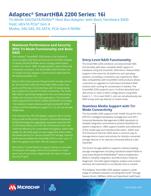
Adaptec® SmartHBA 2200 Series: 16iTri-Mode SAS/SATA/NVMe™ Host Bus Adapter with Basic Hardware RAID Host: x8/x16 PCIe® Gen 4Media: 24G SAS, 6G SATA, PCIe Gen 4 NVMeEntry-Level RAID FunctionalityThe SmartHBA 2200 combines uncompromised HBAfunctionality with basic cacheless RAID support inhardware using the SmartIOC 2200 silicon. Robust RAIDsupport is the same for all platforms and operatingsystems, providing a consistent user experience. Meta-data compatibility with SmartRAID 3200 products allowscustomers to upgrade to a full-feature hardware RAIDsolution with caching for acceleration if needed. TheSmartHBA 2200 supports up to 16 direct-attached harddisk drives or SSDs in RAID configurations using RAIDlevels 0, 1, 10 or even RAID 5, and can simultaneously useRAID arrays and raw devices in mixed mode.Seamless Media Support with Tri-Mode ConnectivityThe SmartHBA 2200 supports both Intel® Virtual Pin Port(VPP) for intelligent backplane management and SFF'sUniversal Backplane Management (UBM) standards tosimplify integration and enhance product flexibility forsystem integrators. UBM support enables auto-detectionof the media type and interface bifurcation. SGPIO andSCSI Enclo s ure Services (SES) allow a common way tomanage device status and activity for directly connectedstorage devices or for devices connected behind a SASexpander.The Smart Storage platform supports industry leadingstorage management including standards-based PlatformLevel Data Model (PLDM)/Redfish® Device Enablement(RDE) to simplify integration and Microchip's ChipLinkDiagnostic Tool with signal integrity analysis and contextsensitive documentation to accelerate time to market.The Adaptec SmartHBA 2200 adapter support a widerange of software solutions including Microsoft® StorageSpaces Direct, VMWare vSAN and OpenStack Swift/Ceph.The Microchip name and logo and the Microchip logo are registered trademarks of Microchip Technology Incorporated in the U.S.A. and other countries. All other trademarks mentioned herein are property of their respective companies. © 2023, Microchip Technology Incorporated and its subsidiaries. All Rights Reserved. 6/23 DS00003269DBenefits• Ideal for enabling PCIe Gen 4 storage capabilities for hyperscale applications, enterprise, and SMB, with proven reliability• Tri-mode support for SAS/SATA/NVMe devices• Combines full-featured, high-performance HBA functional-ity with basic hardware RAID• Built-in PCIe switch to enable ultra-low latency access to NVMe storage devices•Superior performance enabling up to 13 GB/s throughput and 3.5M+ IOPs 4K RRHighlights• Low profile, M D2 form factor• Fully tri-mode capable: 16 Gbps NVMe Gen 4, 24 Gbps SAS-4 and 6 Gbps SATA• 8-lane (x8) PCIe Gen 4 host interface• Internal SlimSAS connector (using SFF-9402 pinout to support U.2 and U.3)• Universal backplane management (UBM) • Virtual Pin Port Management (VPP)• SES (SAS expander-based backplanes), SGPIO (direct attached SAS/SATA backplanes)• Secure boot, secure update and attestation • Dynamic adapter power management • arcconf/maxView support• Support for 64 NVMe devices and up to 256 SAS/SATA devices • Broad inbox OS coverage• Comprehensive out-of-box driver support • Multi-initiator support •Support for x86 platform。
ARTISAN技术组合购物指南说明书

User's Guidee-mail: ************** GPIB HARDWARE MANUAL FOR USE WITHPCI-GPIB, ISA-GPIB142.6 CPCI-GPIB (12)2.5 PC104-GPIB (11)2.4.2 Windows 3.1 (11)2.4.1 Windows 95 (10)2.4 PCM-GPIB (8)2.3 ISA-GPIB/LC (6)2.2 ISA-GPIB (5)2.1 PCI-GPIB (5)CHAPTER TWO: INSTALLATION ...................31.2.3 Connection Configurations . (2)1.2.2 GPIB Electrical Signal Configuration (1)1.2.1 Talkers, Listeners, and Controllers (1)1.2 GPIB SYSTEM DESCRIPTION (1)1.1 HISTORY (1)CHAPTER ONE: INTRODUCTION ......................Chapter One: INTRODUCTION1.1 HISTORYThe GPIB (General Purpose Interface Bus) has become the worldwide standard for connecting instruments to computers. Invented in the 1960s by Hewlett Packard and originally designated as HPIB, the bus specification was eventually adopted by a wide variety of both instrument and computer manufacturers. The original specification was documented and sanctioned by the Institute of Electrical and Electronic Engineers as IEEE-488.The advent of the inexpensive and powerful personal computer has driven the GPIB market through explosive growth. As GPIB bus usage expanded, there arose the need for some additional capability and standardization, so in 1987, IEEE-488.2 was adopted. IEEE-488.2 was revised/ammended in 1992 and represents the current GPIB specification. The new specification provides some standardization among compliant instruments. These standardization greatly simplifies the job of the GPIB system designer since 488.2 compliant instruments share common programming conventions.1.2 GPIB SYSTEM DESCRIPTION1.2.1 Talker s, Listeners, and ControllersA GPIB device can be a Talker, Listener, and/or Controller. As the name implies a Talker sends data to one or more Listeners, A Listener accepts data from a Talker and a Controller manages the flow of information over the bus. A GPIB Digital Voltmeter is acting as a Listener as its input configurations and ranges are set, and then as a Talker when it actually sends its readings to the computer.The Controller is in charge of all communications over the bus. The Controller’s job is to make sure only one device tries to talk at a time, and make sure the correct Lis-teners are paying attention when the Talker talks. Each GPIB system has a single sys-tem controller. The system controller is ultimately in charge of the bus, and is in control as the bus is powered up. There can be more than one Controller on the bus and the System Controller can pass active control to another controller capable device, though only one can be Controller In Charge at a given time. TheGPIB board is usually designated as the System Controller.1.2.2 GPIB Electrical Signal Configuration1The GPIB is an 8-bit parallel data transfer bus. In addition to the 8 data bits, the bus carries three handshaking lines and five GPIB specific management and control lines. The remainder of the standard 24 pin GPIB cable is used for the cable shield, signal grounds and returns. The GPIB connector pin-out is shown in the diagram below:Standard GPIB Cable/ConnectorDATA LINESDIO1 through DIO8 are the data transfer bits. Most GPIB systems send 7-bit data and use the eight bit as a parity or disregard it entirely2HANDSHAKING LINESThere are three handshaking lines that control the data transfer between devices.NRFD (Not Ready For Data): this bit is used to indicate the readiness (or lack thereof) of a device to accept dataDAV (Data Valid): bit is used to indicate to receiving devices that data has been placed on the bus and is available to read.NDAC (Not Data Accepted): is asserted by the receiving device to indicate that data has been read and may now be removed from the bus.SYSTEM MANAGEMENT LINESATN (Attention): is used by the controller to specify how data on the DIO lines is interpreted and which devices must respond to the dataIFC (Interface Clear): is used by the system controller to place the entire system in a known quiescent (Cleared) state and to assert itself as Controller In Charge (CIC).SRQ (Service Request): is used by a device on the bus to indicate the need for atten-tion and requests an interrupt of the current event sequence.REN (Remote Enable): is used by the controller in conjunction with other messages to place a device on the bus into either remote or local modeEOI (End or Identify): Is used by Talkers to indicate the end of a message string, or is used by the Controller to command a polling sequence.1.2.3 Connection ConfigurationsThe GPIB specification is quite definitive regarding the number of devices and cable lengths allowed in a GPIB system. There can be no more than 15 devices on a single contiguous GPIB bus. Larger systems are possible by installing additional GPIB inter-face boards in your computerThe maximum, total length of all cables on a single GPIB system is 20 meters. In addition, cable length between consecutive devices may be no greater than 4 meters, and average cable length must be 2 meters or less. Stated another way, the total cable length (in meters) in the system may not be longer than 2 times the number of devices (up to 20 meters). Longer length systems are possible, but only with the use of a GPIB extender card.In addition to the above rules, at least two thirds of all devices on the bus should be powered on for proper operation.3Keeping the above constraints in mind, there is no limitation on the actual connection scheme used to connect the GPIB devices together. Star, Linear or any combination of both may be used. These are shown in the following diagrams.4,QVWUXPHQW &,QVWUXPHQW ',QVWUXPHQW $,QVWUXPHQW %Linear C onnectionC onfiguration ,QVWUXPHQW ',QVWUXPHQW &,QVWUXPHQW (,QVWUXPHQW $,QVWUXPHQW %S tar C onnectionC onfigurationChapter Two: INSTALLATION The following sections describe the hardware installation procedure for GPIB boards. After hardware installation, please refer to your GPIB software installation guide for additional setup and operation details.2.1 PCI-GPIBThe PCI-GPIB board is completely plug and play. To install this board into your sys-tem follow the simple steps shown below.1. Turn your computer off2. Open your computer case3. Insert the PCI-GPIB into any available PCI slot4. Put your computer’s case back on.5. Turn your computer back on, and follow the instructionsin the GPIB software manual you received with your board.52.2 ISA-GPIBThe only hardware configuration required prior to installing the ISA-GPIB/LC is set-ting the board’s Base Address switch. The location of the Base Address switch is shown in the photograph above, while the switch itself is shown in the diagram on the following page.Most computers will have Base Address 300 Hex (768 decimal) free and the default setting of the board is 300 Hex. If there is already a board in your system using address 300 HEX (768 Decimal), you will have to change the board’s base address prior to installing it in your computer. Other typically free addresses include 310 Hex and 330 Hex.6The following diagram shows the base address in its default 300 Hex setting.987 6 5 4S V65LThe address values corresponding to each of the switches are shown in the following table.Hex Dec.Switch Value Value Default9 200 512 up (200 Hex)8 100 256 up (100 Hex)7 80 128 down (0 Hex)6 40 64 down (0 Hex)5 20 32 down (0 Hex)4 10 16 down (0 Hex)-----------------total 300 HexNote: On this base address switch, Up is on, Down is off. This con-figuration is the opposite of most ISA baseddata acquisition boards.72.3 ISA-GPIB/LCThe following diagram shows the base address in its default 300 Hex setting.987654S V65LThe address values corresponding to each of the switches are shown in the following table.Hex Dec.Switch Value Value Default9200512up (200 Hex)8100256up (100 Hex)7 80128down (0 Hex)6 40 64down (0 Hex)5 20 32down (0 Hex)4 10 16down (0 Hex)-----------------total300 HexNote: On this base address switch, Up is on, Down is off. This con-figuration is the opposite of most ISA based data acquisitionboards.92.4 PCM-GPIBThe installation procedure is different for Windows 95 and DOS/Windows 3.1. These procedures are described below:10:LQGRZVThe PCM-GPIB board is completely plug and play. There are no switches or jumpers to set prior to installation in your computer. Simply follow the steps shown below to install you PCM-GPIB hardware. Once your hardware is installed, please refer to the GPIB-488.2 software manual.1. Start Windows 952. Insert the card into a free PC Card/PCMCIA slot. You do not have toturn the computer off. The system is designed for power on installation.3. Windows 95 will automatically detect the card and depending on theversion of Windows 95 you have, you will either see a New HardwareFound dialog box or a Update Device Driver Wizard box.4. Insert PCM-GPIB Disk 1 into your A drive and follow the instructionsprovided by the dialog box/wizard..If no New Hardware Found dialog box appears, check that you computer’s 32-bit PCMCIA drivers are enabled. This can be checked using the following Windows 95 sequence. Start>Settings>Control Panel>System and look in Performance section. It should read 32-bit. If not, enable 32-bit, shut down your computer and try the above procedure again.:LQGRZVMost users are now installing boards on systems with at least Windows 95 operating systems. However, if you wish to install the PCM-GPIB board in a machine running Windows 3.1 and/or DOS, you will need to use the DOS based Card & Socket serv-ices routine. This is included with most newer computers. However, if you need to purchase these routines, they are available as part number PCM-C&SS from Com-puterBoards for a nominal price. To run the C&SS installation routines, place the PCM-C&SS disk in drive a:, from your boot drive (usually C:) type A:Install and hit enter. Then simply follow the instructions on your screen.The PCM-GPIB hardware is completely plug and play. There are no switches or jumpers to set prior to installation in your computer. Once your hardware is installed, please refer to the GPIB-488.2 software manual.112.5 PC104-GPIBThe only hardware configuration required prior to installing the ISA-GPIB/LC is set-ting the board’s Base Address switch. The location of the Base Address switch is shown in the photograph above, while the switch itself is shown in the diagram on the following page.Most computers will have Base Address 300 Hex (768 decimal) free and the default setting of the board is 300 Hex. If there is already a board in your system using address 300 HEX (768 Decimal), you will have to change the board’s base address prior to installing it in your computer. Other typically free addresses include 310 Hex and 330 Hex.12The following diagram shows the base address in its default 300 Hex setting.987654S V65LThe address values corresponding to each of the switches are shown in the following table.Hex Dec.Switch Value Value Default9200512up (200 Hex)8100256up (100 Hex)7 80128down (0 Hex)6 40 64down (0 Hex)5 20 32down (0 Hex)4 10 16down (0 Hex)-----------------total300 HexNote: On this base address switch, Up is on, Down is off. This con-figuration is the opposite of most PC104 based data acquisitionboards.132.6 CPCI-GPIBThe CPCI-GPIB board is completely plug and play. To install this board install this board into you system follow the simple steps shown below.1. Turn your computer off2. Open your computer front panel (if enclosed)3. Insert the CPCI-GPIB into any available 3U CPCI slot4. Put your computer’s case back on (optional).5. Turn your computer back on, and follow the instructionsin the GPIB software manual you received with your board.14EC Declaration of ConformityDescriptionPart Number Computer to GPIB interface Computer to GPIB interface Computer to GPIB interface Computer to GPIB interface Computer to GPIB interface Computer to GPIB interface ISA-GPIBISA-GPIB/LCPCI-GPIBPC104-GPIBPCM-GPIB CPCI-GPIBto which this declaration relates, meets the essential requirements, is in conformitywith, and CE marking has been applied according to the relevant EC Directives listedbelow using the relevant section of the following EC standards and other normativedocuments:EU EMC Directive 89/336/EEC : Essential requirements relating to electromagneticcompatibility.EU 55022 Class B : Limits and methods of measurements of radio interferencecharacteristics of information technology equipment.EN 50082-1: EC generic immunity requirements.IEC 801-2: Electrostatic discharge requirements for industrial process measurementand control equipment.IEC 801-3: Radiated electromagnetic field requirements for industrial processmeasurements and control equipment.IEC 801-4: Electrically fast transients for industrial process measurement and controlequipment.Carl Haapaoja, Director of Quality Assurance。
- 1、下载文档前请自行甄别文档内容的完整性,平台不提供额外的编辑、内容补充、找答案等附加服务。
- 2、"仅部分预览"的文档,不可在线预览部分如存在完整性等问题,可反馈申请退款(可完整预览的文档不适用该条件!)。
- 3、如文档侵犯您的权益,请联系客服反馈,我们会尽快为您处理(人工客服工作时间:9:00-18:30)。
AmericanPetroleumInstitute682 Standard2nd Edition美国石油协会682标准第二版IntroductionPresented by :邵蔚然约翰克兰(天津)技术部2008-2Pumps-Shaft Sealing Systems for Centrifugal and Rotary Pumps 离心和旋转泵泵轴机械密封系统EAA custAPI 2nd Edition –DescriptionAPI第二版-介绍Written by select committee of:选型协会编写End users最终用户Pump manufacturers泵生产商Seal manufacturers机械密封生产商John Crane API 682 Committee Members约翰克兰API682会员单位 Gordon BuckChris FoneAPI 682 strives to promote:API682要达到的目标:Best practices in selection and operation of mechanical seals机械密封选型和操作方面最好的指南Extend seal life to (3) years service minimum机械密封使用寿命延长到3年Built upon growing acceptance of API 682 1st Edition在API682第一版的基础上有很大的改进Technically equivalent to ISO Draft International Standard 21049技术标准与ISO21049草案等同API 682 Task forceAPI682 编委会1st Edition Taskforce was refineries only第一版仅炼化行业 2nd Edition Taskforce第二版new chairman (Joe Thorp)新的主席3 members from 1st edition第一版的3个成员chemical plant representatives化工厂的代表 input from PIP committees由PIP委员会注入 European representatives欧洲的代表John Crane representatives约翰克兰的代表Gordon BuckChris Fone (ESA)Chris Fone from JC EAAAPI 682 Publication DatesAPI 682出版日程1st Edition issued 1994 1994年发布第一版 2nd Edition July 2002 2002年7月第二版 ISO 21049 issued 20043nd Edition issued September 2004API 682 Mission Statement API682 声明“This standard is designed todefault to the equipment types most commonly supplied that havea high probability of meeting the objective of at least three years of uninterrupted service whilecomplying with emissions regulations.”这个标准的使命是为了使大多数设备能够在规定的泄漏范内至少连续运行3年.API 682 Standard -Aims API 682标准-目的Maximum reliability and availability of equipment 设备最高的可靠性和可使用性Meet emissions legislation 符合法定的泄漏要求Lower costs -standardisation & reliability 低成本-标准化和可靠性Improved safety -tested & proven sealing systems 安全性提高-已测试和验证的密封系统Consistent seal application based on accumulation of best practices 最好的实践积累的机械密封应用 Seal interchange ability 机械密封互换性API682总结Only three arrangements只有三种布置Single 单密封dual unpressurised无压双密封dual pressurised 加压双密封Testing on five fluid groups, 5种流体测试Propane, water, caustic, cold oil, hot oil丙烷,水,腐蚀性物质,冷油,热油Specifies materials of construction结构件采用指定材料Secondary containment on all single seals所有单密封都带有二次阻封Forced circulation on dual seals双机械密封采取强制循环Full interchange ability完全的互换性Continued....API682总结Guidelines for seal and hardware design based upon user experience 机械密封和硬件设计以用户的实践经验为指导Tested designs 试验设计Qualification type testing 资质检测Individual component & seal integrity testing 单独的零件和机械密封完整性检测Defined guidelines for auxiliary equipment, pipe work & instrumentation辅助系统,管道和仪表的定义指南API 676 Positive DisplacementPumpsAPI 6107th Edition Pumps and SealsAPI 610 8th Edition Mainly PumpsAPI 682 1st Edition Seals OnlyDevelopment of Seal & Pump Standards机械密封和泵标准的发展API 6109th Edition/ISO 13709 Only PumpsAPI 6822nd EditionSeals OnlyISO 21049Seals OnlyDevelopment of Seal & Pump Standards 机械密封和泵标准的发展ANSI Strategy is to drive US Standards into ISO美国国家标准化组织的策略是推动美国标准并入ISO标准API 610 (7th) -issued 1989API 610 (8th) -issued 1995API 682 (1st) -issued 1994API 610 (9th) combined with ISO 13709 -DIS vote 2001-4, issued 2003-1?API 682 (2nd) positive vote Sept 2001 -issued 2002-3 ISO 21049 -DIS vote 2002-2, issued 2003-3?API 682 (3rd) -issued 2003-3?DIN24960EN12756L1k/L1n Seal dimensions ISO3069Chamber dimsAPI 610 9th ISO13709API610 8thAPI682Table 1DIN + 5mm Cartridge API682 Cat 2/3ISO3069H DIN24960chambersISO3069 SISO3069C API682 Cat 1ASME B73 (Big Bore)Replaces the long-standing mechanical seals specification found in API 610 Pump Standard 替换了API610泵标准里繁琐的机械密封说明 Replaces and expands the scope of API 682 1st Edition:替换和扩展了API682第一版的范围:Adds new seal types 加入新的密封类型Adds new piping plans 加入新的管路方案Establishes (3) seal categories 建立了(3)种密封分类 Adds seals for chemical plants (ANSI & ISO chemical duty pumps)增加了用于化工厂的机械密封(ANSI 和ISO 化工泵) Adds qualification tests for new seal types 为新的机械密封类型添加了质量测试Adds pass/fail criteria for qualification tests 为质量测试添加了通过和不通过的标准To be ISO Standard 21049 将成为ISO21049标准What’s New in 2nd /3nd Edition第二/三版有什么新的内容API 2nd Edition –DescriptionAPI第二版-描述Specification now includes:新包含的说明:Dry-running secondary containment seals干运转二次密封Non-contacting seals非接触式密封Gas lubricated seals气体润滑密封New piping arrangements for secondary containment and non-contacting seals用于二次密封和非接触式密封的新冲洗方案安排API 2nd Edition –Benefits API第二版-益处Consistency of approach方法的连续性 Proven practices已经过实践证明Qualification tested质量测试International in scope国际标准Results结果Reliability可靠性Low leakage低泄漏Long life长寿命Cost effective有效成本API-682 1st Ed. Significance?API-682第一版的意义?1st Edition released in 1994.1994年发布第一版Few US customers have specified seals as pure 682 1st Ed.compliant.很少美国用户能够适应纯粹的682第一版API-682 1st Ed. sales growing slowly primarily through international projects. API-682第一版在国际项目中增长缓慢Still generally limited understanding and use of the specification.有限的理解和使用Market unwilling to accept cost impact associated with technical requirements of the specification.市场对技术要求的成本不接受。